EP2821741B1 - Procédé de rééquipement d'un ensemble cryostat pour refroidissement par circulation - Google Patents
Procédé de rééquipement d'un ensemble cryostat pour refroidissement par circulation Download PDFInfo
- Publication number
- EP2821741B1 EP2821741B1 EP14174819.4A EP14174819A EP2821741B1 EP 2821741 B1 EP2821741 B1 EP 2821741B1 EP 14174819 A EP14174819 A EP 14174819A EP 2821741 B1 EP2821741 B1 EP 2821741B1
- Authority
- EP
- European Patent Office
- Prior art keywords
- container
- cooling medium
- cooling
- cooling circuit
- nitrogen
- Prior art date
- Legal status (The legal status is an assumption and is not a legal conclusion. Google has not performed a legal analysis and makes no representation as to the accuracy of the status listed.)
- Active
Links
Images


Classifications
-
- F—MECHANICAL ENGINEERING; LIGHTING; HEATING; WEAPONS; BLASTING
- F25—REFRIGERATION OR COOLING; COMBINED HEATING AND REFRIGERATION SYSTEMS; HEAT PUMP SYSTEMS; MANUFACTURE OR STORAGE OF ICE; LIQUEFACTION SOLIDIFICATION OF GASES
- F25B—REFRIGERATION MACHINES, PLANTS OR SYSTEMS; COMBINED HEATING AND REFRIGERATION SYSTEMS; HEAT PUMP SYSTEMS
- F25B9/00—Compression machines, plants or systems, in which the refrigerant is air or other gas of low boiling point
- F25B9/002—Compression machines, plants or systems, in which the refrigerant is air or other gas of low boiling point characterised by the refrigerant
-
- F—MECHANICAL ENGINEERING; LIGHTING; HEATING; WEAPONS; BLASTING
- F25—REFRIGERATION OR COOLING; COMBINED HEATING AND REFRIGERATION SYSTEMS; HEAT PUMP SYSTEMS; MANUFACTURE OR STORAGE OF ICE; LIQUEFACTION SOLIDIFICATION OF GASES
- F25B—REFRIGERATION MACHINES, PLANTS OR SYSTEMS; COMBINED HEATING AND REFRIGERATION SYSTEMS; HEAT PUMP SYSTEMS
- F25B9/00—Compression machines, plants or systems, in which the refrigerant is air or other gas of low boiling point
-
- F—MECHANICAL ENGINEERING; LIGHTING; HEATING; WEAPONS; BLASTING
- F25—REFRIGERATION OR COOLING; COMBINED HEATING AND REFRIGERATION SYSTEMS; HEAT PUMP SYSTEMS; MANUFACTURE OR STORAGE OF ICE; LIQUEFACTION SOLIDIFICATION OF GASES
- F25D—REFRIGERATORS; COLD ROOMS; ICE-BOXES; COOLING OR FREEZING APPARATUS NOT OTHERWISE PROVIDED FOR
- F25D17/00—Arrangements for circulating cooling fluids; Arrangements for circulating gas, e.g. air, within refrigerated spaces
-
- F—MECHANICAL ENGINEERING; LIGHTING; HEATING; WEAPONS; BLASTING
- F25—REFRIGERATION OR COOLING; COMBINED HEATING AND REFRIGERATION SYSTEMS; HEAT PUMP SYSTEMS; MANUFACTURE OR STORAGE OF ICE; LIQUEFACTION SOLIDIFICATION OF GASES
- F25D—REFRIGERATORS; COLD ROOMS; ICE-BOXES; COOLING OR FREEZING APPARATUS NOT OTHERWISE PROVIDED FOR
- F25D19/00—Arrangement or mounting of refrigeration units with respect to devices or objects to be refrigerated, e.g. infrared detectors
-
- G—PHYSICS
- G01—MEASURING; TESTING
- G01R—MEASURING ELECTRIC VARIABLES; MEASURING MAGNETIC VARIABLES
- G01R33/00—Arrangements or instruments for measuring magnetic variables
- G01R33/20—Arrangements or instruments for measuring magnetic variables involving magnetic resonance
- G01R33/28—Details of apparatus provided for in groups G01R33/44 - G01R33/64
- G01R33/38—Systems for generation, homogenisation or stabilisation of the main or gradient magnetic field
- G01R33/3804—Additional hardware for cooling or heating of the magnet assembly, for housing a cooled or heated part of the magnet assembly or for temperature control of the magnet assembly
-
- G—PHYSICS
- G01—MEASURING; TESTING
- G01R—MEASURING ELECTRIC VARIABLES; MEASURING MAGNETIC VARIABLES
- G01R33/00—Arrangements or instruments for measuring magnetic variables
- G01R33/20—Arrangements or instruments for measuring magnetic variables involving magnetic resonance
- G01R33/28—Details of apparatus provided for in groups G01R33/44 - G01R33/64
- G01R33/38—Systems for generation, homogenisation or stabilisation of the main or gradient magnetic field
- G01R33/381—Systems for generation, homogenisation or stabilisation of the main or gradient magnetic field using electromagnets
- G01R33/3815—Systems for generation, homogenisation or stabilisation of the main or gradient magnetic field using electromagnets with superconducting coils, e.g. power supply therefor
-
- H—ELECTRICITY
- H01—ELECTRIC ELEMENTS
- H01F—MAGNETS; INDUCTANCES; TRANSFORMERS; SELECTION OF MATERIALS FOR THEIR MAGNETIC PROPERTIES
- H01F6/00—Superconducting magnets; Superconducting coils
- H01F6/04—Cooling
-
- F—MECHANICAL ENGINEERING; LIGHTING; HEATING; WEAPONS; BLASTING
- F17—STORING OR DISTRIBUTING GASES OR LIQUIDS
- F17C—VESSELS FOR CONTAINING OR STORING COMPRESSED, LIQUEFIED OR SOLIDIFIED GASES; FIXED-CAPACITY GAS-HOLDERS; FILLING VESSELS WITH, OR DISCHARGING FROM VESSELS, COMPRESSED, LIQUEFIED, OR SOLIDIFIED GASES
- F17C2221/00—Handled fluid, in particular type of fluid
- F17C2221/01—Pure fluids
- F17C2221/014—Nitrogen
-
- F—MECHANICAL ENGINEERING; LIGHTING; HEATING; WEAPONS; BLASTING
- F17—STORING OR DISTRIBUTING GASES OR LIQUIDS
- F17C—VESSELS FOR CONTAINING OR STORING COMPRESSED, LIQUEFIED OR SOLIDIFIED GASES; FIXED-CAPACITY GAS-HOLDERS; FILLING VESSELS WITH, OR DISCHARGING FROM VESSELS, COMPRESSED, LIQUEFIED, OR SOLIDIFIED GASES
- F17C2221/00—Handled fluid, in particular type of fluid
- F17C2221/01—Pure fluids
- F17C2221/016—Noble gases (Ar, Kr, Xe)
- F17C2221/017—Helium
-
- F—MECHANICAL ENGINEERING; LIGHTING; HEATING; WEAPONS; BLASTING
- F17—STORING OR DISTRIBUTING GASES OR LIQUIDS
- F17C—VESSELS FOR CONTAINING OR STORING COMPRESSED, LIQUEFIED OR SOLIDIFIED GASES; FIXED-CAPACITY GAS-HOLDERS; FILLING VESSELS WITH, OR DISCHARGING FROM VESSELS, COMPRESSED, LIQUEFIED, OR SOLIDIFIED GASES
- F17C2270/00—Applications
- F17C2270/05—Applications for industrial use
- F17C2270/0527—Superconductors
- F17C2270/0536—Magnetic resonance imaging
Definitions
- the invention relates to a method for converting a cryostat assembly having a room temperature vacuum container in which a first container is arranged with a liquid helium bath, the operating temperature is maintained by helium evaporation below 5 K, wherein in the room temperature vacuum container also a second container, in which lead coolant lines, is arranged, which can be filled for thermal shielding of the first container with liquid nitrogen and held by nitrogen evaporation at an operating temperature of 75 to 80 K.
- Such a cryostat arrangement is used in particular for the cooling of superconducting magnet coils.
- NMR spectroscopy represents a powerful method of instrumental analysis.
- superconducting magnetic coils are used, which are preferably operated in liquid helium.
- the magnetic coil and the liquid helium are housed in a first container.
- the temperature of this vessel remains constant by continuous evaporation of the helium.
- one or more radiation shields can be arranged around this container. Between these radiation shields and the external room temperature vacuum container there is arranged an annular second container which is filled with liquid nitrogen and whose temperature is kept constant at approximately 77 K by continuous evaporation of the nitrogen.
- FIG. 8 shown.
- a major disadvantage of this arrangement is that the handling of the cryogen used is not very easy and therefore requires specially trained personnel. By refilling also creates a generally undesirable interruption of the measurements in the refrigerated apparatus.
- the dependency on the supply of liquid cryogens is particularly problematic where there is no optimal infrastructure for this, such as in emerging countries (such as India, African countries, etc.). Also, a future increase in price or scarcity of cryogens makes such a kind of cooling quite expensive.
- cryostat arrangement could also collect the evaporating cryogens outside the cryostat arrangement and liquefy them again with a separate cryosystem.
- a separate cryosystem for example, offered by the company Cryomech ("Liquid Helium Plants"), but has the disadvantages that exclusively Helium is liquefied and this must be transferred back to the cryostat arrangement in relatively short intervals again.
- the present invention is therefore an object of the invention to provide a method for converting a Kryostatan extract with the features defined with the simplest possible technical measures so that the above enumerated disadvantages of the prior art are largely avoided, at least no liquid nitrogen are used got to. It is another object of the present invention to substantially reduce the helium consumption of the cryostat assembly, and also to allow for uninterrupted operation over a long period of time with only minimal mechanical disturbances.
- the container According to the original intended function of the second container is changed to the effect that no liquid nitrogen is used and the container instead can be cooled by another cooling medium with a lower boiling point to a temperature below 60 K, which is in no way achievable with nitrogen, since this already frozen at 63K.
- Refrigerators which achieve the required cooling capacities and temperatures below 60 K, are commercially available. For example, can be used as refrigerators such as pulse tube, Gifford-McMahon or Stirling cooler. However, it has never been considered by the relevant experts to use such refrigerators in a closed cooling circuit for cooling the cryogen (previously always nitrogen) in the second container, but exclusively only for cooling or for re-liquefaction of helium in the first container.
- the evaporation rate of liquid helium in the first container is largely determined by the heat input in the form of heat radiation and Heat conduction between the first container and the second container arranged around it. This is usually at a constant temperature, which - so far - was determined by the boiling point of the nitrogen, which is at a pressure of 1 bar at about 77K.
- One way to reduce the evaporation rate of liquid helium from the first container is therefore very easy by reducing the temperature of the second container (compared to the usual temperature level of liquid nitrogen).
- the second container By converting the second container to a cooling by another cooling fluid with a much lower boiling point compared to nitrogen, the evaporation rate of helium from the first container to much lower values (for example, 50% of normal) can be reduced because the cooling medium in gaseous state has a very good thermal contact with the second container, the second container thus assumes the temperature of the cooling medium.
- the lower evaporation rate of helium also has the great advantage that helium must be refilled less frequently and only at longer intervals. In this way, holding times of over one year are easily achievable. This is particularly advantageous in those countries in which the procurement of liquid helium is possible only at long intervals and the price of the same is particularly high.
- the system according to the invention also has the advantage that it is connected to the second container of the cryostat arrangement only by means of flexible vacuum-insulated coolant lines. Therefore, the refrigerator can be freely placed next to it, with no room height restrictions and space requirements.
- the second container can also be operated with a cryogenic fluid other than nitrogen, but this cooling fluid is always liquid is.
- DE 42 27 388 A1 serves a pulse tube cooler by mechanical coupling of the cold stage of the cooling of the nitrogen tank.
- the present invention assumes that the cooling medium in the second container is in the gaseous phase.
- the second container to be cooled is always filled with a liquid cooling medium.
- liquid nitrogen usually present in the second container can also be replaced by another liquid cooling medium in order to reach even lower temperatures.
- gaseous helium or neon is used as the fluid cooling medium.
- These two lightest noble gases have been used in cryogenic technology for many decades to produce particularly low temperatures, because they remain gaseous to low temperatures under normal conditions, while nitrogen already freezes at 63K.
- helium condenses only at 4.2 K and helium gas is much easier to obtain in the form of compressed gas cylinders than liquid helium.
- a heat exchanger is arranged in the second container and connected to the coolant lines of the cooling circuit and the cooling medium is cooled by the heat exchanger to an operating temperature of ⁇ 60 K. Advantages and mode of operation are described in detail in the description of Fig. 2 refer to.
- the second container which is supplemented or exchanged during the conversion of the cryostat arrangement by the introduced gaseous cooling medium, is filled with liquid nitrogen before the conversion.
- the retrofitting is done in a system which is already in its original configuration, i. with evaporating nitrogen in the second container, is in operation and is now converted by the method according to the invention. This method is advantageous because all already delivered to customers and in operation cryostat arrangements can be converted in a very straightforward way.
- the cooling circuit comprises a compressor, which is designed as a compressor of the refrigerator, as a cold gas compressor or as operated at ambient temperature pump, which is integrated by a countercurrent heat exchanger in the cooling circuit.
- a compressor which is designed as a compressor of the refrigerator, as a cold gas compressor or as operated at ambient temperature pump, which is integrated by a countercurrent heat exchanger in the cooling circuit.
- a countercurrent heat exchanger is typically used, as it is widely used in heating and refrigeration.
- cryostat assembly which are characterized in that the cooling circuit has a Joule-Thomson expansion stage. Advantages and mode of operation are described in detail in the description of Fig. 7 refer to.
- the present invention relates to a method for converting a cryostat arrangement, as it is already known in principle from the prior art, which is schematically shown in FIG Fig. 8 illustrated and discussed in detail above.
- the cryostat assembly 1 comprises a room temperature vacuum container 10 , in which a first container 2 is arranged with a liquid helium bath 3 , the operating temperature is maintained by helium evaporation at below 5 K, wherein in the room temperature vacuum container 10 also a second container 6, which fills the thermal shielding of the first container 2 with a liquid nitrogen bath 7 and can be maintained by nitrogen evaporation at an operating temperature of 75 to 80 K.
- FIG. 8 Cryostat assembly 1 shown in the prior art - and also the arrangement of Figures 1-7 - are typically used for NMR devices.
- the first, filled with liquid helium 3 container 2 of the assembly 1 contains a generally superconducting magnet assembly 4 and is surrounded by a radiation shield 5 , which in turn is surrounded by the second container 6, the liquid nitrogen 7 contains.
- the room temperature vacuum container 10 encloses the two containers 2, 6 and the radiation shield 5.
- the first container 2 has a filling opening 9 and the second container 6 has a filling opening 8 through which the evaporating cryogens can escape on the one hand and on the other hand for the Refilling can be used.
- the helium evaporation rate from the first container 2 is determined by the heat input from the outside due to radiation and heat conduction through the filling openings 8, 9.
- the helium evaporation rate typically maintained in the range of about 100 ml / hr.
- the present invention is characterized in that - in the course of a conversion or post-armament of a cryostat assembly 1 according to the prior art - a fluid cooling medium 12 is introduced into the second container 6, which at a temperature of 60 K and a pressure of 1 bar is gaseous, and that the cooling medium 12 is cooled by a refrigerator 16 by means of a cooling circuit 11, the coolant lines lead into the second container 6 into an operating temperature of ⁇ 60 K.
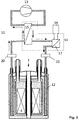
- Fig.1 schematically illustrates an embodiment of the cryostat assembly 1 with the cooling circuit 11, which is connected to the filling openings of the second container 6.
- the cooling medium in the second container 6 is identical to the coolant which circulates in the cooling circuit 11.
- the cooling medium 12 is passed from a compressor 13 via a countercurrent heat exchanger 15 to a second heat exchanger 17 , which is cooled by the refrigerator 16.
- the cooling medium 12 then flows through the second container 6 and cools it to a temperature of less than 60 K.
- the emerging from the second container 6 cooling medium 12 then flows through the counterflow heat exchanger 15 back to the compressor 13.
- the heat exchanger 15, 17 and refrigerator 16 are installed in a closed cold box 14, which is kept under vacuum.
- Fig. 2 shows a similar embodiment as Fig. 1 in which, however, the cooling medium 12 in the second container 6 does not correspond to the coolant 18 circulating in the cooling circuit 11 .
- the heat exchange in the second container 6 takes place via the surface of a heat exchange element 19. This element can be introduced into the second container 6, for example in the form of a long tube.
- cooling circuit 11 is configured completely tight against the cryostat 1.
- another coolant 18 can be used in the cooling circuit 11 and the working pressure of the coolant 18 is independent of the working pressure in the second container 6. Since due to a corresponding mechanical design of the second container 6 only a slight overpressure against the atmosphere is possible in the cooling circuit 11 a much higher pressure can be selected, whereby the density of the coolant 18 is higher and the thermodynamic efficiency of the cooling loop can be increased.
- the coolant lines may conduct vibrations from the compressor 13 and refrigerator 16 to the cryostat assembly 1. With very sensitive, in particular high-resolution spectroscopic measurements, these vibrations can lead to unacceptable disturbances in the measurement signal. Compared to the embodiment of Fig. 1 are therefore at the in Fig. 3 shown arrangement, the coolant lines mechanically connected to damping elements 20 for damping the vibrations.
- damping elements may be active or passive in nature and for example consist of a solid metal base, with which the coolant line is positively connected to dampen vibrations.
- cryostat 1 a cooling medium tank 21 connected to the coolant circuit 11.
- the cooling medium tank 21 has the task to accommodate a supply of cooling medium 12 and 18 and to keep the pressure in the cooling circuit 11 as constant as possible.
- the cooling medium tank 21 may comprise, for example, a pressure bottle, which is connected via a pressure reducing valve with the coolant circuit 11.
- a cold gas compressor 23 integrated into the cold box 14 and operates at the temperature of the cold coolant 12.
- This has the advantage that the coolant 12 does not have to be heated in a countercurrent heat exchanger before it reaches the compressor 23.
- Such compressors operating at low temperatures are sold, for example, by Cryozone BV.
- the efficiency of the coolant circuit 11 can be significantly increased again and still reduce costs, since a countercurrent heat exchanger is eliminated.
- cryostat assembly 1 Compared to the arrangement according to Fig. 6 will be at the in Fig. 7 illustrated cryostat assembly 1, the coolant 12 when entering the second container 6 via a Joule-Thomson expansion valve 24 relaxed. Depending on the temperature and pressure can relax by relaxing a gas, the temperature drop and thus an additional cooling effect can be achieved. This effect is used for example in the well-known Linde process for the liquefaction of air.
- This additional cooling can be utilized when the compressor 23 achieves high compression of the coolant 12 and for the coolant 12 a suitable gas such as neon is used. In order for even lower temperatures can be achieved in the second container 6, which in turn lowers the evaporation rate of helium from the first container 2 on.
Landscapes
- Engineering & Computer Science (AREA)
- Physics & Mathematics (AREA)
- Mechanical Engineering (AREA)
- Thermal Sciences (AREA)
- General Engineering & Computer Science (AREA)
- Condensed Matter Physics & Semiconductors (AREA)
- General Physics & Mathematics (AREA)
- Chemical & Material Sciences (AREA)
- Combustion & Propulsion (AREA)
- Power Engineering (AREA)
- Electromagnetism (AREA)
- Containers, Films, And Cooling For Superconductive Devices (AREA)
Claims (11)
- Procédé de rééquipement d'un ensemble cryostat (1) qui présente une enceinte sous vide à température ambiante (10) dans laquelle est disposé un premier récipient (2) contenant un bain d'hélium liquide (3), dont la température de service est maintenue au-dessous de 5 K par évaporation d'hélium, dans laquelle enceinte sous vide à température ambiante (10) est en outre disposé un deuxième récipient (6) dans lequel conduisent des conduites d'agent de refroidissement, lequel est rempli d'azote liquide (7) pour l'isolation thermique du premier récipient (2) et peut être maintenu à une température de service de 75 à 80 K par évaporation d'azote, caractérisé en ce
qu'un milieu de refroidissement fluide (12), lequel est gazeux à une température de 60 K et une pression de 1 bar et présente un point d'ébullition sensiblement plus faible que l'azote, est introduit dans le deuxième récipient (6), et que le milieu de refroidissement (12) est refroidi à l'état gazeux à une température de service ≤ 60 K par un réfrigérateur (16) au moyen d'un circuit de refroidissement (11) dont les conduites d'agent de refroidissement conduisent dans le deuxième récipient (6). - Procédé selon la revendication 1, caractérisé en ce que de l'hélium ou du néon à l'état gazeux est utilisé comme milieu de refroidissement fluide (12).
- Procédé selon la revendication 1 ou la revendication 2, caractérisé en ce qu'un échangeur de chaleur (19) est disposé dans le deuxième récipient (6) et raccordé aux conduites d'agent de refroidissement du circuit de refroidissement, et que le milieu de refroidissement (12) est refroidi à une température de service ≤ 60 K au moyen de l'échangeur de chaleur (19).
- Procédé de rééquipement d'un ensemble cryostat (1) selon la revendication 1 ou la revendication 2, caractérisé en ce que les conduites d'agent de refroidissement du circuit de refroidissement (11) sont ouvertes à l'intérieur du deuxième récipient (6), de sorte que le milieu de refroidissement (12) est conduit du deuxième récipient (6) dans les conduites d'agent de refroidissement du circuit de refroidissement (11) et refroidi à une température de service ≤ 60 K.
- Procédé selon l'une des revendications précédentes, caractérisé en ce que le deuxième récipient (6) est rempli, avant le rééquipement, d'azote liquide (7) qui, lors du rééquipement de l'ensemble cryostat (1), est complété ou remplacé par le milieu de refroidissement gazeux (12) introduit.
- Procédé selon l'une des revendications précédentes, caractérisé en ce qu'en plus du milieu de refroidissement fluide (12), on laisse et/ou introduit dans le deuxième récipient (6) une quantité d'azote (22) qui occupe un volume d'au moins 5 1 à une température de service ≤ 60 K.
- Procédé selon l'une des revendications précédentes, caractérisé en ce que l'ensemble cryostat fait partie d'un appareil pour la résonance magnétique nucléaire et sert à refroidir un ensemble d'aimants supraconducteurs (4).
- Procédé selon l'une des revendications précédentes, caractérisé en ce qu'un élément d'amortissement (20) est intégré dans les conduites d'agent de refroidissement du circuit de refroidissement (11) pour l'isolation des vibrations mécaniques.
- Procédé selon l'une des revendications précédentes, caractérisé en ce que l'ensemble cryostat présente un réservoir de milieu de refroidissement (21) disposé à l'extérieur de l'enceinte sous vide à température ambiante (10), au moyen duquel le deuxième récipient (6) et/ou le circuit de refroidissement (11) est alimenté en milieu de refroidissement (12) pour s'opposer aux fluctuations de pression.
- Procédé selon l'une des revendications précédentes, caractérisé en ce que le circuit de refroidissement (11) présente un compresseur (13) qui est réalisé sous la forme d'un compresseur du réfrigérateur (16), d'un compresseur de gaz froid (23) ou d'une pompe fonctionnant à température ambiante qui est intégrée dans le circuit de refroidissement (11) par un échangeur de chaleur à contre-courant (15).
- Procédé selon l'une des revendications précédentes, caractérisé en ce que le circuit de refroidissement (11) présente un étage de détente Joule-Thomson (24).
Applications Claiming Priority (1)
| Application Number | Priority Date | Filing Date | Title |
|---|---|---|---|
| DE201310213020 DE102013213020A1 (de) | 2013-07-03 | 2013-07-03 | Verfahren zum Umrüsten einer Kryostatanordnung auf Umlaufkühlung |
Publications (3)
| Publication Number | Publication Date |
|---|---|
| EP2821741A2 EP2821741A2 (fr) | 2015-01-07 |
| EP2821741A3 EP2821741A3 (fr) | 2015-05-20 |
| EP2821741B1 true EP2821741B1 (fr) | 2016-04-27 |
Family
ID=51210991
Family Applications (1)
| Application Number | Title | Priority Date | Filing Date |
|---|---|---|---|
| EP14174819.4A Active EP2821741B1 (fr) | 2013-07-03 | 2014-06-27 | Procédé de rééquipement d'un ensemble cryostat pour refroidissement par circulation |
Country Status (3)
| Country | Link |
|---|---|
| US (1) | US9494344B2 (fr) |
| EP (1) | EP2821741B1 (fr) |
| DE (1) | DE102013213020A1 (fr) |
Families Citing this family (16)
| Publication number | Priority date | Publication date | Assignee | Title |
|---|---|---|---|---|
| JP6445752B2 (ja) * | 2013-06-28 | 2018-12-26 | 株式会社東芝 | 超電導磁石装置 |
| DE102014214796A1 (de) * | 2014-07-28 | 2016-01-28 | Bruker Biospin Ag | Verfahren zum Laden einer supraleitfähigen Magnetanordnung mit Strom |
| US10490329B2 (en) * | 2015-04-10 | 2019-11-26 | Mitsubishi Electric Corporation | Superconducting magnet |
| DE102015105804A1 (de) * | 2015-04-16 | 2016-10-20 | Netzsch-Feinmahltechnik Gmbh | Rührwerkskugelmühle |
| DE102015212314B3 (de) * | 2015-07-01 | 2016-10-20 | Bruker Biospin Gmbh | Kryostat mit aktiver Halsrohrkühlung durch ein zweites Kryogen |
| GB201515701D0 (en) * | 2015-09-04 | 2015-10-21 | Tokamak Energy Ltd | Cryogenics for HTS magnets |
| WO2017068469A1 (fr) * | 2015-10-15 | 2017-04-27 | Victoria Link Ltd | Procédé et appareil de refroidissement d'un dispositif supraconducteur immergé dans de l'azote liquide |
| JP6528652B2 (ja) * | 2015-11-12 | 2019-06-12 | 住友電装株式会社 | 導電部材及び端子付導電部材 |
| DE102016214731B3 (de) * | 2016-08-09 | 2017-07-27 | Bruker Biospin Ag | NMR-Apparatur mit supraleitender Magnetanordnung sowie gekühlten Probenkopfkomponenten |
| US11275136B2 (en) | 2016-10-06 | 2022-03-15 | Koninklijke Philips N.V. | Passive flow direction biasing of cryogenic thermosiphon |
| JP7139303B2 (ja) * | 2019-11-01 | 2022-09-20 | ジャパンスーパーコンダクタテクノロジー株式会社 | クライオスタット用ヘリウム再凝縮装置 |
| DE102020201522A1 (de) * | 2020-02-07 | 2021-08-12 | Bruker Switzerland Ag | NMR-Messanordnung mit kalter Bohrung des Kryostaten |
| CN112712958B (zh) * | 2020-12-23 | 2023-01-31 | 中国科学院电工研究所 | 一种液氮屏蔽混合液体介质冷却的高温超导磁体 |
| EP4426983A4 (fr) * | 2021-11-02 | 2025-09-17 | Anyon Systems Inc | Réfrigérateur à dilution comprenant un liquéfacteur d'hélium à écoulement continu |
| CN114637349B (zh) * | 2022-03-04 | 2023-04-11 | 中国科学院电工研究所 | 一种液氦温区恒温装置及恒温控制方法 |
| DE102022209941A1 (de) * | 2022-09-21 | 2024-03-21 | Bruker Switzerland Ag | Vorrichtung zum Transfer von flüssigem Helium, mit verringerten Transfer-Verlusten |
Family Cites Families (22)
| Publication number | Priority date | Publication date | Assignee | Title |
|---|---|---|---|---|
| JPS5932758A (ja) * | 1982-08-16 | 1984-02-22 | 株式会社日立製作所 | 冷凍機付クライオスタツト |
| DE3916212A1 (de) | 1989-05-18 | 1990-11-22 | Spectrospin Ag | Verfahren und vorrichtung zum vorkuehlen des heliumtanks eines kryostaten |
| DE4017213C1 (fr) * | 1990-05-29 | 1991-05-23 | Bruker Analytische Messtechnik Gmbh, 7512 Rheinstetten, De | |
| DE4106135A1 (de) | 1991-02-27 | 1992-09-03 | Spectrospin Ag | Kryomagnetsystem mit stoerungsminimiertem low-loss-heliumkryostat |
| DE4227388C2 (de) | 1992-08-19 | 1996-09-12 | Spectrospin Ag | Kryostat mit mechanisch flexibler thermischer Kontaktierung |
| US5402648A (en) | 1993-07-01 | 1995-04-04 | Apd Cryogenics Inc. | Sealed dewar with separate circulation loop for external cooling at constant pressure |
| US5563566A (en) | 1995-11-13 | 1996-10-08 | General Electric Company | Cryogen-cooled open MRI superconductive magnet |
| DE19548273A1 (de) * | 1995-12-22 | 1997-06-26 | Spectrospin Ag | NMR-Meßeinrichtung mit Pulsrohrkühler |
| US5613367A (en) | 1995-12-28 | 1997-03-25 | General Electric Company | Cryogen recondensing superconducting magnet |
| GB2329701B (en) | 1997-09-30 | 2001-09-19 | Oxford Magnet Tech | Load bearing means in nmr cryostat systems |
| US6181228B1 (en) * | 1999-11-09 | 2001-01-30 | General Electric Company | Superconductive magnet including a cryocooler coldhead |
| GB0403113D0 (en) * | 2004-02-12 | 2004-03-17 | Magnex Scient Ltd | Superconducting magnet systems |
| DE102004012416B4 (de) * | 2004-03-13 | 2006-04-20 | Bruker Biospin Gmbh | Supraleitendes Magnetsystem mit Pulsrohr-Kühler |
| DE102004037173B3 (de) * | 2004-07-30 | 2005-12-15 | Bruker Biospin Ag | Vorrichtung zur kryogenverlustfreien Kühlung einer Kryostatanordnung |
| DE102004053972B3 (de) * | 2004-11-09 | 2006-07-20 | Bruker Biospin Gmbh | NMR-Spektrometer mit gemeinsamen Refrigerator zum Kühlen von NMR-Probenkopf und Kryostat |
| DE102004053973B3 (de) | 2004-11-09 | 2006-07-20 | Bruker Biospin Ag | NMR-Spektrometer mit Refrigeratorkühlung |
| DE102004060832B3 (de) * | 2004-12-17 | 2006-06-14 | Bruker Biospin Gmbh | NMR-Spektrometer mit gemeinsamen Refrigerator zum Kühlen von NMR-Probenkopf und Kryostat |
| DE102005029151B4 (de) * | 2005-06-23 | 2008-08-07 | Bruker Biospin Ag | Kryostatanordnung mit Kryokühler |
| GB2433581B (en) | 2005-12-22 | 2008-02-27 | Siemens Magnet Technology Ltd | Closed-loop precooling of cryogenically cooled equipment |
| DE102006012509B3 (de) * | 2006-03-18 | 2007-10-04 | Bruker Biospin Gmbh | Kryostat mit einem Magnetspulensystem, das eine LTS- und eine im Vakuumteil angeordnete HTS-Sektion umfasst |
| US20090301129A1 (en) * | 2008-06-08 | 2009-12-10 | Wang Nmr Inc. | Helium and nitrogen reliquefying apparatus |
| DE102011005888B4 (de) * | 2011-03-22 | 2014-01-09 | Bruker Biospin Ag | Kühlung eines Kryo-Probenkopfes in einer Kernspinresonanz-Apparatur |
-
2013
- 2013-07-03 DE DE201310213020 patent/DE102013213020A1/de not_active Withdrawn
-
2014
- 2014-06-27 EP EP14174819.4A patent/EP2821741B1/fr active Active
- 2014-07-01 US US14/320,670 patent/US9494344B2/en active Active
Also Published As
| Publication number | Publication date |
|---|---|
| US20150007586A1 (en) | 2015-01-08 |
| EP2821741A3 (fr) | 2015-05-20 |
| US9494344B2 (en) | 2016-11-15 |
| EP2821741A2 (fr) | 2015-01-07 |
| DE102013213020A1 (de) | 2015-01-08 |
Similar Documents
| Publication | Publication Date | Title |
|---|---|---|
| EP2821741B1 (fr) | Procédé de rééquipement d'un ensemble cryostat pour refroidissement par circulation | |
| DE102004053972B3 (de) | NMR-Spektrometer mit gemeinsamen Refrigerator zum Kühlen von NMR-Probenkopf und Kryostat | |
| DE69838866T2 (de) | Verbesserungen in oder mit Bezug auf Kryostatsystemen | |
| DE102011078608B4 (de) | Kryostatanordnung | |
| DE19914778B4 (de) | Supraleitende Magnetvorrichtung | |
| DE102005041383B4 (de) | NMR-Apparatur mit gemeinsam gekühltem Probenkopf und Kryobehälter und Verfahren zum Betrieb derselben | |
| DE102004037172B4 (de) | Kryostatanordnung | |
| DE102004037173B3 (de) | Vorrichtung zur kryogenverlustfreien Kühlung einer Kryostatanordnung | |
| DE10033410C1 (de) | Kreislaufkryostat | |
| DE102004053973B3 (de) | NMR-Spektrometer mit Refrigeratorkühlung | |
| EP1736723B1 (fr) | Dispositif de cryostat avec cryorefroidisseur | |
| DE102015215919B4 (de) | Verfahren und Vorrichtung zur Vorkühlung eines Kryostaten | |
| DE102011013577B4 (de) | Vorrichtung zur Speicherung von Wasserstoff und von magnetischer Energie sowie ein Verfahren zu ihrem Betrieb | |
| DE102011005888B4 (de) | Kühlung eines Kryo-Probenkopfes in einer Kernspinresonanz-Apparatur | |
| DE19548273A1 (de) | NMR-Meßeinrichtung mit Pulsrohrkühler | |
| EP3282270B1 (fr) | Appareil rmn pourvu d'un système d'aimants supraconducteurs et composants formant sondes refroidis | |
| DE102004061869A1 (de) | Einrichtung der Supraleitungstechnik | |
| EP3611528B1 (fr) | Dispositif cryostat pourvu de système de bobines magnétiques supraconducteur à ancrage thermique de la structure de fixation | |
| DE102022209941A1 (de) | Vorrichtung zum Transfer von flüssigem Helium, mit verringerten Transfer-Verlusten | |
| DE102009027429B4 (de) | Verfahren zur Kühlung einer Kryostatenanordnung während des Transports, Kryostatenanordnung mit Transportkühleinheit und Transportcontainer zum Transportieren der Kryostatenanordnung | |
| DE102004012416B4 (de) | Supraleitendes Magnetsystem mit Pulsrohr-Kühler | |
| EP4575352A1 (fr) | Dispositif et procédé de transfert d'hélium liquide dans un cryostat d'application | |
| EP1742234B1 (fr) | Ensemble de cryostat horizontal en surfusion | |
| DE102004012452A1 (de) | Supraleitendes Magnetsystem mit Pulsrohr-Kühler | |
| DE202005010892U1 (de) | Unterkühlte Horizontalkryostatanordnung |
Legal Events
| Date | Code | Title | Description |
|---|---|---|---|
| PUAI | Public reference made under article 153(3) epc to a published international application that has entered the european phase |
Free format text: ORIGINAL CODE: 0009012 |
|
| 17P | Request for examination filed |
Effective date: 20140627 |
|
| AK | Designated contracting states |
Kind code of ref document: A2 Designated state(s): AL AT BE BG CH CY CZ DE DK EE ES FI FR GB GR HR HU IE IS IT LI LT LU LV MC MK MT NL NO PL PT RO RS SE SI SK SM TR |
|
| AX | Request for extension of the european patent |
Extension state: BA ME |
|
| PUAL | Search report despatched |
Free format text: ORIGINAL CODE: 0009013 |
|
| AK | Designated contracting states |
Kind code of ref document: A3 Designated state(s): AL AT BE BG CH CY CZ DE DK EE ES FI FR GB GR HR HU IE IS IT LI LT LU LV MC MK MT NL NO PL PT RO RS SE SI SK SM TR |
|
| AX | Request for extension of the european patent |
Extension state: BA ME |
|
| RIC1 | Information provided on ipc code assigned before grant |
Ipc: F25D 19/00 20060101AFI20150410BHEP Ipc: F25D 17/00 20060101ALI20150410BHEP |
|
| R17P | Request for examination filed (corrected) |
Effective date: 20150605 |
|
| RBV | Designated contracting states (corrected) |
Designated state(s): AL AT BE BG CH CY CZ DE DK EE ES FI FR GB GR HR HU IE IS IT LI LT LU LV MC MK MT NL NO PL PT RO RS SE SI SK SM TR |
|
| GRAP | Despatch of communication of intention to grant a patent |
Free format text: ORIGINAL CODE: EPIDOSNIGR1 |
|
| INTG | Intention to grant announced |
Effective date: 20151105 |
|
| GRAS | Grant fee paid |
Free format text: ORIGINAL CODE: EPIDOSNIGR3 |
|
| GRAA | (expected) grant |
Free format text: ORIGINAL CODE: 0009210 |
|
| AK | Designated contracting states |
Kind code of ref document: B1 Designated state(s): AL AT BE BG CH CY CZ DE DK EE ES FI FR GB GR HR HU IE IS IT LI LT LU LV MC MK MT NL NO PL PT RO RS SE SI SK SM TR |
|
| REG | Reference to a national code |
Ref country code: GB Ref legal event code: FG4D Free format text: NOT ENGLISH |
|
| REG | Reference to a national code |
Ref country code: CH Ref legal event code: EP |
|
| REG | Reference to a national code |
Ref country code: AT Ref legal event code: REF Ref document number: 795272 Country of ref document: AT Kind code of ref document: T Effective date: 20160515 |
|
| REG | Reference to a national code |
Ref country code: IE Ref legal event code: FG4D Free format text: LANGUAGE OF EP DOCUMENT: GERMAN |
|
| REG | Reference to a national code |
Ref country code: DE Ref legal event code: R096 Ref document number: 502014000691 Country of ref document: DE |
|
| REG | Reference to a national code |
Ref country code: FR Ref legal event code: PLFP Year of fee payment: 3 |
|
| REG | Reference to a national code |
Ref country code: LT Ref legal event code: MG4D |
|
| REG | Reference to a national code |
Ref country code: NL Ref legal event code: MP Effective date: 20160427 |
|
| PG25 | Lapsed in a contracting state [announced via postgrant information from national office to epo] |
Ref country code: NL Free format text: LAPSE BECAUSE OF FAILURE TO SUBMIT A TRANSLATION OF THE DESCRIPTION OR TO PAY THE FEE WITHIN THE PRESCRIBED TIME-LIMIT Effective date: 20160427 |
|
| PG25 | Lapsed in a contracting state [announced via postgrant information from national office to epo] |
Ref country code: PL Free format text: LAPSE BECAUSE OF FAILURE TO SUBMIT A TRANSLATION OF THE DESCRIPTION OR TO PAY THE FEE WITHIN THE PRESCRIBED TIME-LIMIT Effective date: 20160427 Ref country code: NO Free format text: LAPSE BECAUSE OF FAILURE TO SUBMIT A TRANSLATION OF THE DESCRIPTION OR TO PAY THE FEE WITHIN THE PRESCRIBED TIME-LIMIT Effective date: 20160727 Ref country code: FI Free format text: LAPSE BECAUSE OF FAILURE TO SUBMIT A TRANSLATION OF THE DESCRIPTION OR TO PAY THE FEE WITHIN THE PRESCRIBED TIME-LIMIT Effective date: 20160427 Ref country code: LT Free format text: LAPSE BECAUSE OF FAILURE TO SUBMIT A TRANSLATION OF THE DESCRIPTION OR TO PAY THE FEE WITHIN THE PRESCRIBED TIME-LIMIT Effective date: 20160427 |
|
| PG25 | Lapsed in a contracting state [announced via postgrant information from national office to epo] |
Ref country code: HR Free format text: LAPSE BECAUSE OF FAILURE TO SUBMIT A TRANSLATION OF THE DESCRIPTION OR TO PAY THE FEE WITHIN THE PRESCRIBED TIME-LIMIT Effective date: 20160427 Ref country code: LV Free format text: LAPSE BECAUSE OF FAILURE TO SUBMIT A TRANSLATION OF THE DESCRIPTION OR TO PAY THE FEE WITHIN THE PRESCRIBED TIME-LIMIT Effective date: 20160427 Ref country code: GR Free format text: LAPSE BECAUSE OF FAILURE TO SUBMIT A TRANSLATION OF THE DESCRIPTION OR TO PAY THE FEE WITHIN THE PRESCRIBED TIME-LIMIT Effective date: 20160728 Ref country code: PT Free format text: LAPSE BECAUSE OF FAILURE TO SUBMIT A TRANSLATION OF THE DESCRIPTION OR TO PAY THE FEE WITHIN THE PRESCRIBED TIME-LIMIT Effective date: 20160829 Ref country code: ES Free format text: LAPSE BECAUSE OF FAILURE TO SUBMIT A TRANSLATION OF THE DESCRIPTION OR TO PAY THE FEE WITHIN THE PRESCRIBED TIME-LIMIT Effective date: 20160427 Ref country code: SE Free format text: LAPSE BECAUSE OF FAILURE TO SUBMIT A TRANSLATION OF THE DESCRIPTION OR TO PAY THE FEE WITHIN THE PRESCRIBED TIME-LIMIT Effective date: 20160427 Ref country code: RS Free format text: LAPSE BECAUSE OF FAILURE TO SUBMIT A TRANSLATION OF THE DESCRIPTION OR TO PAY THE FEE WITHIN THE PRESCRIBED TIME-LIMIT Effective date: 20160427 |
|
| PG25 | Lapsed in a contracting state [announced via postgrant information from national office to epo] |
Ref country code: IT Free format text: LAPSE BECAUSE OF FAILURE TO SUBMIT A TRANSLATION OF THE DESCRIPTION OR TO PAY THE FEE WITHIN THE PRESCRIBED TIME-LIMIT Effective date: 20160427 Ref country code: BE Free format text: LAPSE BECAUSE OF NON-PAYMENT OF DUE FEES Effective date: 20160630 |
|
| REG | Reference to a national code |
Ref country code: DE Ref legal event code: R097 Ref document number: 502014000691 Country of ref document: DE |
|
| PG25 | Lapsed in a contracting state [announced via postgrant information from national office to epo] |
Ref country code: SK Free format text: LAPSE BECAUSE OF FAILURE TO SUBMIT A TRANSLATION OF THE DESCRIPTION OR TO PAY THE FEE WITHIN THE PRESCRIBED TIME-LIMIT Effective date: 20160427 Ref country code: CZ Free format text: LAPSE BECAUSE OF FAILURE TO SUBMIT A TRANSLATION OF THE DESCRIPTION OR TO PAY THE FEE WITHIN THE PRESCRIBED TIME-LIMIT Effective date: 20160427 Ref country code: MC Free format text: LAPSE BECAUSE OF FAILURE TO SUBMIT A TRANSLATION OF THE DESCRIPTION OR TO PAY THE FEE WITHIN THE PRESCRIBED TIME-LIMIT Effective date: 20160427 Ref country code: RO Free format text: LAPSE BECAUSE OF FAILURE TO SUBMIT A TRANSLATION OF THE DESCRIPTION OR TO PAY THE FEE WITHIN THE PRESCRIBED TIME-LIMIT Effective date: 20160427 Ref country code: EE Free format text: LAPSE BECAUSE OF FAILURE TO SUBMIT A TRANSLATION OF THE DESCRIPTION OR TO PAY THE FEE WITHIN THE PRESCRIBED TIME-LIMIT Effective date: 20160427 Ref country code: DK Free format text: LAPSE BECAUSE OF FAILURE TO SUBMIT A TRANSLATION OF THE DESCRIPTION OR TO PAY THE FEE WITHIN THE PRESCRIBED TIME-LIMIT Effective date: 20160427 |
|
| PG25 | Lapsed in a contracting state [announced via postgrant information from national office to epo] |
Ref country code: SM Free format text: LAPSE BECAUSE OF FAILURE TO SUBMIT A TRANSLATION OF THE DESCRIPTION OR TO PAY THE FEE WITHIN THE PRESCRIBED TIME-LIMIT Effective date: 20160427 |
|
| PLBE | No opposition filed within time limit |
Free format text: ORIGINAL CODE: 0009261 |
|
| STAA | Information on the status of an ep patent application or granted ep patent |
Free format text: STATUS: NO OPPOSITION FILED WITHIN TIME LIMIT |
|
| REG | Reference to a national code |
Ref country code: IE Ref legal event code: MM4A |
|
| 26N | No opposition filed |
Effective date: 20170130 |
|
| PG25 | Lapsed in a contracting state [announced via postgrant information from national office to epo] |
Ref country code: SI Free format text: LAPSE BECAUSE OF FAILURE TO SUBMIT A TRANSLATION OF THE DESCRIPTION OR TO PAY THE FEE WITHIN THE PRESCRIBED TIME-LIMIT Effective date: 20160427 Ref country code: IE Free format text: LAPSE BECAUSE OF NON-PAYMENT OF DUE FEES Effective date: 20160627 |
|
| REG | Reference to a national code |
Ref country code: FR Ref legal event code: PLFP Year of fee payment: 4 |
|
| PG25 | Lapsed in a contracting state [announced via postgrant information from national office to epo] |
Ref country code: HU Free format text: LAPSE BECAUSE OF FAILURE TO SUBMIT A TRANSLATION OF THE DESCRIPTION OR TO PAY THE FEE WITHIN THE PRESCRIBED TIME-LIMIT; INVALID AB INITIO Effective date: 20140627 |
|
| REG | Reference to a national code |
Ref country code: FR Ref legal event code: PLFP Year of fee payment: 5 |
|
| PG25 | Lapsed in a contracting state [announced via postgrant information from national office to epo] |
Ref country code: MK Free format text: LAPSE BECAUSE OF FAILURE TO SUBMIT A TRANSLATION OF THE DESCRIPTION OR TO PAY THE FEE WITHIN THE PRESCRIBED TIME-LIMIT Effective date: 20160427 Ref country code: LU Free format text: LAPSE BECAUSE OF NON-PAYMENT OF DUE FEES Effective date: 20160627 Ref country code: MT Free format text: LAPSE BECAUSE OF FAILURE TO SUBMIT A TRANSLATION OF THE DESCRIPTION OR TO PAY THE FEE WITHIN THE PRESCRIBED TIME-LIMIT Effective date: 20160427 Ref country code: CY Free format text: LAPSE BECAUSE OF FAILURE TO SUBMIT A TRANSLATION OF THE DESCRIPTION OR TO PAY THE FEE WITHIN THE PRESCRIBED TIME-LIMIT Effective date: 20160427 Ref country code: IS Free format text: LAPSE BECAUSE OF FAILURE TO SUBMIT A TRANSLATION OF THE DESCRIPTION OR TO PAY THE FEE WITHIN THE PRESCRIBED TIME-LIMIT Effective date: 20160427 |
|
| PG25 | Lapsed in a contracting state [announced via postgrant information from national office to epo] |
Ref country code: BG Free format text: LAPSE BECAUSE OF FAILURE TO SUBMIT A TRANSLATION OF THE DESCRIPTION OR TO PAY THE FEE WITHIN THE PRESCRIBED TIME-LIMIT Effective date: 20160427 |
|
| PG25 | Lapsed in a contracting state [announced via postgrant information from national office to epo] |
Ref country code: TR Free format text: LAPSE BECAUSE OF FAILURE TO SUBMIT A TRANSLATION OF THE DESCRIPTION OR TO PAY THE FEE WITHIN THE PRESCRIBED TIME-LIMIT Effective date: 20160427 Ref country code: AL Free format text: LAPSE BECAUSE OF FAILURE TO SUBMIT A TRANSLATION OF THE DESCRIPTION OR TO PAY THE FEE WITHIN THE PRESCRIBED TIME-LIMIT Effective date: 20160427 |
|
| REG | Reference to a national code |
Ref country code: DE Ref legal event code: R082 Ref document number: 502014000691 Country of ref document: DE Representative=s name: KOHLER SCHMID MOEBUS PATENTANWAELTE PARTNERSCH, DE Ref country code: DE Ref legal event code: R081 Ref document number: 502014000691 Country of ref document: DE Owner name: BRUKER SWITZERLAND AG, CH Free format text: FORMER OWNER: BRUKER BIOSPIN AG, FAELLANDEN, CH |
|
| REG | Reference to a national code |
Ref country code: CH Ref legal event code: PFA Owner name: BRUKER SWITZERLAND AG, CH Free format text: FORMER OWNER: BRUKER BIOSPIN AG, CH |
|
| REG | Reference to a national code |
Ref country code: AT Ref legal event code: MM01 Ref document number: 795272 Country of ref document: AT Kind code of ref document: T Effective date: 20190627 |
|
| PG25 | Lapsed in a contracting state [announced via postgrant information from national office to epo] |
Ref country code: AT Free format text: LAPSE BECAUSE OF NON-PAYMENT OF DUE FEES Effective date: 20190627 |
|
| P01 | Opt-out of the competence of the unified patent court (upc) registered |
Effective date: 20231221 |
|
| PGFP | Annual fee paid to national office [announced via postgrant information from national office to epo] |
Ref country code: DE Payment date: 20250618 Year of fee payment: 12 |
|
| PGFP | Annual fee paid to national office [announced via postgrant information from national office to epo] |
Ref country code: GB Payment date: 20250620 Year of fee payment: 12 |
|
| PGFP | Annual fee paid to national office [announced via postgrant information from national office to epo] |
Ref country code: FR Payment date: 20250626 Year of fee payment: 12 |
|
| PGFP | Annual fee paid to national office [announced via postgrant information from national office to epo] |
Ref country code: CH Payment date: 20250701 Year of fee payment: 12 |