EP2823162B1 - Composant de post-traitement des gaz d'échappement présentant une fonction d'adsorption des hydrocarbures et système d'échappement pourvu d'un tel composant - Google Patents
Composant de post-traitement des gaz d'échappement présentant une fonction d'adsorption des hydrocarbures et système d'échappement pourvu d'un tel composant Download PDFInfo
- Publication number
- EP2823162B1 EP2823162B1 EP13703579.6A EP13703579A EP2823162B1 EP 2823162 B1 EP2823162 B1 EP 2823162B1 EP 13703579 A EP13703579 A EP 13703579A EP 2823162 B1 EP2823162 B1 EP 2823162B1
- Authority
- EP
- European Patent Office
- Prior art keywords
- exhaust
- aftertreatment component
- exhaust gas
- gas aftertreatment
- inner region
- Prior art date
- Legal status (The legal status is an assumption and is not a legal conclusion. Google has not performed a legal analysis and makes no representation as to the accuracy of the status listed.)
- Not-in-force
Links
Images

Classifications
-
- F—MECHANICAL ENGINEERING; LIGHTING; HEATING; WEAPONS; BLASTING
- F01—MACHINES OR ENGINES IN GENERAL; ENGINE PLANTS IN GENERAL; STEAM ENGINES
- F01N—GAS-FLOW SILENCERS OR EXHAUST APPARATUS FOR MACHINES OR ENGINES IN GENERAL; GAS-FLOW SILENCERS OR EXHAUST APPARATUS FOR INTERNAL-COMBUSTION ENGINES
- F01N3/00—Exhaust or silencing apparatus having means for purifying, rendering innocuous, or otherwise treating exhaust
- F01N3/08—Exhaust or silencing apparatus having means for purifying, rendering innocuous, or otherwise treating exhaust for rendering innocuous
- F01N3/0807—Exhaust or silencing apparatus having means for purifying, rendering innocuous, or otherwise treating exhaust for rendering innocuous by using absorbents or adsorbents
- F01N3/0828—Exhaust or silencing apparatus having means for purifying, rendering innocuous, or otherwise treating exhaust for rendering innocuous by using absorbents or adsorbents characterised by the absorbed or adsorbed substances
- F01N3/0835—Hydrocarbons
-
- B—PERFORMING OPERATIONS; TRANSPORTING
- B01—PHYSICAL OR CHEMICAL PROCESSES OR APPARATUS IN GENERAL
- B01D—SEPARATION
- B01D53/00—Separation of gases or vapours; Recovering vapours of volatile solvents from gases; Chemical or biological purification of waste gases, e.g. engine exhaust gases, smoke, fumes, flue gases, aerosols
- B01D53/02—Separation of gases or vapours; Recovering vapours of volatile solvents from gases; Chemical or biological purification of waste gases, e.g. engine exhaust gases, smoke, fumes, flue gases, aerosols by adsorption, e.g. preparative gas chromatography
- B01D53/04—Separation of gases or vapours; Recovering vapours of volatile solvents from gases; Chemical or biological purification of waste gases, e.g. engine exhaust gases, smoke, fumes, flue gases, aerosols by adsorption, e.g. preparative gas chromatography with stationary adsorbents
-
- F—MECHANICAL ENGINEERING; LIGHTING; HEATING; WEAPONS; BLASTING
- F01—MACHINES OR ENGINES IN GENERAL; ENGINE PLANTS IN GENERAL; STEAM ENGINES
- F01N—GAS-FLOW SILENCERS OR EXHAUST APPARATUS FOR MACHINES OR ENGINES IN GENERAL; GAS-FLOW SILENCERS OR EXHAUST APPARATUS FOR INTERNAL-COMBUSTION ENGINES
- F01N13/00—Exhaust or silencing apparatus characterised by constructional features
- F01N13/011—Exhaust or silencing apparatus characterised by constructional features having two or more purifying devices arranged in parallel
- F01N13/017—Exhaust or silencing apparatus characterised by constructional features having two or more purifying devices arranged in parallel the purifying devices are arranged in a single housing
-
- F—MECHANICAL ENGINEERING; LIGHTING; HEATING; WEAPONS; BLASTING
- F01—MACHINES OR ENGINES IN GENERAL; ENGINE PLANTS IN GENERAL; STEAM ENGINES
- F01N—GAS-FLOW SILENCERS OR EXHAUST APPARATUS FOR MACHINES OR ENGINES IN GENERAL; GAS-FLOW SILENCERS OR EXHAUST APPARATUS FOR INTERNAL-COMBUSTION ENGINES
- F01N13/00—Exhaust or silencing apparatus characterised by constructional features
- F01N13/16—Selection of particular materials
-
- F—MECHANICAL ENGINEERING; LIGHTING; HEATING; WEAPONS; BLASTING
- F01—MACHINES OR ENGINES IN GENERAL; ENGINE PLANTS IN GENERAL; STEAM ENGINES
- F01N—GAS-FLOW SILENCERS OR EXHAUST APPARATUS FOR MACHINES OR ENGINES IN GENERAL; GAS-FLOW SILENCERS OR EXHAUST APPARATUS FOR INTERNAL-COMBUSTION ENGINES
- F01N3/00—Exhaust or silencing apparatus having means for purifying, rendering innocuous, or otherwise treating exhaust
- F01N3/08—Exhaust or silencing apparatus having means for purifying, rendering innocuous, or otherwise treating exhaust for rendering innocuous
- F01N3/0807—Exhaust or silencing apparatus having means for purifying, rendering innocuous, or otherwise treating exhaust for rendering innocuous by using absorbents or adsorbents
- F01N3/0814—Exhaust or silencing apparatus having means for purifying, rendering innocuous, or otherwise treating exhaust for rendering innocuous by using absorbents or adsorbents combined with catalytic converters, e.g. NOx absorption/storage reduction catalysts
-
- F—MECHANICAL ENGINEERING; LIGHTING; HEATING; WEAPONS; BLASTING
- F01—MACHINES OR ENGINES IN GENERAL; ENGINE PLANTS IN GENERAL; STEAM ENGINES
- F01N—GAS-FLOW SILENCERS OR EXHAUST APPARATUS FOR MACHINES OR ENGINES IN GENERAL; GAS-FLOW SILENCERS OR EXHAUST APPARATUS FOR INTERNAL-COMBUSTION ENGINES
- F01N3/00—Exhaust or silencing apparatus having means for purifying, rendering innocuous, or otherwise treating exhaust
- F01N3/08—Exhaust or silencing apparatus having means for purifying, rendering innocuous, or otherwise treating exhaust for rendering innocuous
- F01N3/10—Exhaust or silencing apparatus having means for purifying, rendering innocuous, or otherwise treating exhaust for rendering innocuous by thermal or catalytic conversion of noxious components of exhaust
- F01N3/101—Three-way catalysts
-
- F—MECHANICAL ENGINEERING; LIGHTING; HEATING; WEAPONS; BLASTING
- F01—MACHINES OR ENGINES IN GENERAL; ENGINE PLANTS IN GENERAL; STEAM ENGINES
- F01N—GAS-FLOW SILENCERS OR EXHAUST APPARATUS FOR MACHINES OR ENGINES IN GENERAL; GAS-FLOW SILENCERS OR EXHAUST APPARATUS FOR INTERNAL-COMBUSTION ENGINES
- F01N3/00—Exhaust or silencing apparatus having means for purifying, rendering innocuous, or otherwise treating exhaust
- F01N3/08—Exhaust or silencing apparatus having means for purifying, rendering innocuous, or otherwise treating exhaust for rendering innocuous
- F01N3/10—Exhaust or silencing apparatus having means for purifying, rendering innocuous, or otherwise treating exhaust for rendering innocuous by thermal or catalytic conversion of noxious components of exhaust
- F01N3/105—General auxiliary catalysts, e.g. upstream or downstream of the main catalyst
-
- F—MECHANICAL ENGINEERING; LIGHTING; HEATING; WEAPONS; BLASTING
- F01—MACHINES OR ENGINES IN GENERAL; ENGINE PLANTS IN GENERAL; STEAM ENGINES
- F01N—GAS-FLOW SILENCERS OR EXHAUST APPARATUS FOR MACHINES OR ENGINES IN GENERAL; GAS-FLOW SILENCERS OR EXHAUST APPARATUS FOR INTERNAL-COMBUSTION ENGINES
- F01N3/00—Exhaust or silencing apparatus having means for purifying, rendering innocuous, or otherwise treating exhaust
- F01N3/08—Exhaust or silencing apparatus having means for purifying, rendering innocuous, or otherwise treating exhaust for rendering innocuous
- F01N3/10—Exhaust or silencing apparatus having means for purifying, rendering innocuous, or otherwise treating exhaust for rendering innocuous by thermal or catalytic conversion of noxious components of exhaust
- F01N3/24—Exhaust or silencing apparatus having means for purifying, rendering innocuous, or otherwise treating exhaust for rendering innocuous by thermal or catalytic conversion of noxious components of exhaust characterised by constructional aspects of converting apparatus
- F01N3/28—Construction of catalytic reactors
- F01N3/2803—Construction of catalytic reactors characterised by structure, by material or by manufacturing of catalyst support
- F01N3/2825—Ceramics
- F01N3/2828—Ceramic multi-channel monoliths, e.g. honeycombs
-
- B—PERFORMING OPERATIONS; TRANSPORTING
- B01—PHYSICAL OR CHEMICAL PROCESSES OR APPARATUS IN GENERAL
- B01D—SEPARATION
- B01D2257/00—Components to be removed
- B01D2257/70—Organic compounds not provided for in groups B01D2257/00 - B01D2257/602
- B01D2257/702—Hydrocarbons
-
- F—MECHANICAL ENGINEERING; LIGHTING; HEATING; WEAPONS; BLASTING
- F01—MACHINES OR ENGINES IN GENERAL; ENGINE PLANTS IN GENERAL; STEAM ENGINES
- F01N—GAS-FLOW SILENCERS OR EXHAUST APPARATUS FOR MACHINES OR ENGINES IN GENERAL; GAS-FLOW SILENCERS OR EXHAUST APPARATUS FOR INTERNAL-COMBUSTION ENGINES
- F01N2240/00—Combination or association of two or more different exhaust treating devices, or of at least one such device with an auxiliary device, not covered by indexing codes F01N2230/00 or F01N2250/00, one of the devices being
- F01N2240/20—Combination or association of two or more different exhaust treating devices, or of at least one such device with an auxiliary device, not covered by indexing codes F01N2230/00 or F01N2250/00, one of the devices being a flow director or deflector
-
- F—MECHANICAL ENGINEERING; LIGHTING; HEATING; WEAPONS; BLASTING
- F01—MACHINES OR ENGINES IN GENERAL; ENGINE PLANTS IN GENERAL; STEAM ENGINES
- F01N—GAS-FLOW SILENCERS OR EXHAUST APPARATUS FOR MACHINES OR ENGINES IN GENERAL; GAS-FLOW SILENCERS OR EXHAUST APPARATUS FOR INTERNAL-COMBUSTION ENGINES
- F01N2240/00—Combination or association of two or more different exhaust treating devices, or of at least one such device with an auxiliary device, not covered by indexing codes F01N2230/00 or F01N2250/00, one of the devices being
- F01N2240/36—Combination or association of two or more different exhaust treating devices, or of at least one such device with an auxiliary device, not covered by indexing codes F01N2230/00 or F01N2250/00, one of the devices being an exhaust flap
-
- F—MECHANICAL ENGINEERING; LIGHTING; HEATING; WEAPONS; BLASTING
- F01—MACHINES OR ENGINES IN GENERAL; ENGINE PLANTS IN GENERAL; STEAM ENGINES
- F01N—GAS-FLOW SILENCERS OR EXHAUST APPARATUS FOR MACHINES OR ENGINES IN GENERAL; GAS-FLOW SILENCERS OR EXHAUST APPARATUS FOR INTERNAL-COMBUSTION ENGINES
- F01N2250/00—Combinations of different methods of purification
- F01N2250/14—Combinations of different methods of purification absorption or adsorption, and filtering
-
- F—MECHANICAL ENGINEERING; LIGHTING; HEATING; WEAPONS; BLASTING
- F01—MACHINES OR ENGINES IN GENERAL; ENGINE PLANTS IN GENERAL; STEAM ENGINES
- F01N—GAS-FLOW SILENCERS OR EXHAUST APPARATUS FOR MACHINES OR ENGINES IN GENERAL; GAS-FLOW SILENCERS OR EXHAUST APPARATUS FOR INTERNAL-COMBUSTION ENGINES
- F01N2330/00—Structure of catalyst support or particle filter
- F01N2330/30—Honeycomb supports characterised by their structural details
- F01N2330/32—Honeycomb supports characterised by their structural details characterised by the shape, form or number of corrugations of plates, sheets or foils
- F01N2330/321—Honeycomb supports characterised by their structural details characterised by the shape, form or number of corrugations of plates, sheets or foils with two or more different kinds of corrugations in the same substrate
-
- F—MECHANICAL ENGINEERING; LIGHTING; HEATING; WEAPONS; BLASTING
- F01—MACHINES OR ENGINES IN GENERAL; ENGINE PLANTS IN GENERAL; STEAM ENGINES
- F01N—GAS-FLOW SILENCERS OR EXHAUST APPARATUS FOR MACHINES OR ENGINES IN GENERAL; GAS-FLOW SILENCERS OR EXHAUST APPARATUS FOR INTERNAL-COMBUSTION ENGINES
- F01N2330/00—Structure of catalyst support or particle filter
- F01N2330/30—Honeycomb supports characterised by their structural details
- F01N2330/48—Honeycomb supports characterised by their structural details characterised by the number of flow passages, e.g. cell density
-
- F—MECHANICAL ENGINEERING; LIGHTING; HEATING; WEAPONS; BLASTING
- F01—MACHINES OR ENGINES IN GENERAL; ENGINE PLANTS IN GENERAL; STEAM ENGINES
- F01N—GAS-FLOW SILENCERS OR EXHAUST APPARATUS FOR MACHINES OR ENGINES IN GENERAL; GAS-FLOW SILENCERS OR EXHAUST APPARATUS FOR INTERNAL-COMBUSTION ENGINES
- F01N2410/00—By-passing, at least partially, exhaust from inlet to outlet of apparatus, to atmosphere or to other device
- F01N2410/12—By-passing, at least partially, exhaust from inlet to outlet of apparatus, to atmosphere or to other device in case of absorption, adsorption or desorption of exhaust gas constituents
-
- F—MECHANICAL ENGINEERING; LIGHTING; HEATING; WEAPONS; BLASTING
- F01—MACHINES OR ENGINES IN GENERAL; ENGINE PLANTS IN GENERAL; STEAM ENGINES
- F01N—GAS-FLOW SILENCERS OR EXHAUST APPARATUS FOR MACHINES OR ENGINES IN GENERAL; GAS-FLOW SILENCERS OR EXHAUST APPARATUS FOR INTERNAL-COMBUSTION ENGINES
- F01N3/00—Exhaust or silencing apparatus having means for purifying, rendering innocuous, or otherwise treating exhaust
- F01N3/08—Exhaust or silencing apparatus having means for purifying, rendering innocuous, or otherwise treating exhaust for rendering innocuous
- F01N3/0807—Exhaust or silencing apparatus having means for purifying, rendering innocuous, or otherwise treating exhaust for rendering innocuous by using absorbents or adsorbents
- F01N3/0821—Exhaust or silencing apparatus having means for purifying, rendering innocuous, or otherwise treating exhaust for rendering innocuous by using absorbents or adsorbents combined with particulate filter
-
- Y—GENERAL TAGGING OF NEW TECHNOLOGICAL DEVELOPMENTS; GENERAL TAGGING OF CROSS-SECTIONAL TECHNOLOGIES SPANNING OVER SEVERAL SECTIONS OF THE IPC; TECHNICAL SUBJECTS COVERED BY FORMER USPC CROSS-REFERENCE ART COLLECTIONS [XRACs] AND DIGESTS
- Y02—TECHNOLOGIES OR APPLICATIONS FOR MITIGATION OR ADAPTATION AGAINST CLIMATE CHANGE
- Y02A—TECHNOLOGIES FOR ADAPTATION TO CLIMATE CHANGE
- Y02A50/00—TECHNOLOGIES FOR ADAPTATION TO CLIMATE CHANGE in human health protection, e.g. against extreme weather
- Y02A50/20—Air quality improvement or preservation, e.g. vehicle emission control or emission reduction by using catalytic converters
-
- Y—GENERAL TAGGING OF NEW TECHNOLOGICAL DEVELOPMENTS; GENERAL TAGGING OF CROSS-SECTIONAL TECHNOLOGIES SPANNING OVER SEVERAL SECTIONS OF THE IPC; TECHNICAL SUBJECTS COVERED BY FORMER USPC CROSS-REFERENCE ART COLLECTIONS [XRACs] AND DIGESTS
- Y02—TECHNOLOGIES OR APPLICATIONS FOR MITIGATION OR ADAPTATION AGAINST CLIMATE CHANGE
- Y02T—CLIMATE CHANGE MITIGATION TECHNOLOGIES RELATED TO TRANSPORTATION
- Y02T10/00—Road transport of goods or passengers
- Y02T10/10—Internal combustion engine [ICE] based vehicles
- Y02T10/12—Improving ICE efficiencies
Definitions
- the invention relates to an exhaust aftertreatment component with an HC adsorber, an exhaust system comprising this exhaust gas purification system and a vehicle having such an exhaust system.
- oxidation catalysts which convert unburned hydrocarbons (HC) and carbon monoxide (CO), and in diesel and gasoline engines reduction catalysts that convert nitrogen oxides (NO X ).
- NO X nitrogen oxides
- three-way catalysts which combine the function of oxidation and reduction catalysts and thus convert all three components catalytically and are used mainly in gasoline engines.
- all catalysts require a specific minimum temperature in order to provide sufficient conversion performance.
- the so-called light-off or light-off temperature is used, in which the catalyst converts 50% of the limited exhaust gas components. After a cold start of the engine, this temperature is usually not reached, so that if no further measures are taken, the emissions referred to as start emissions leave the exhaust system without conversion.
- precatalysts which are also referred to as start catalysts. Due to their low volume and near-to-engine placement, pre-catalysts reach their light-off temperature relatively quickly and then convert most of the emissions until a downstream main catalytic converter reaches its operating temperature.
- an exhaust gas catalytic converter with a monolithic ceramic carrier body which has an inner area and an outer area, the inner area having a higher cell density than the outer area.
- the carrier body axially traversing flow channels of the inner and outer areas have a catalytic coating (washcoat) on. Due to the higher cell density of the inner area, it has a higher catalyst activity than the outer area.
- a swirl generator is arranged, which at low flow velocities of the exhaust gas, ie at low engine load ranges, directs the exhaust gas flow substantially into the inner region and at higher flow velocities, ie higher loads, into the outer region.
- US 2002/0132726 A1 describes an exhaust system having a main catalyst and downstream of this two parallel exhaust pipes, which can be selectively closed or opened by means of a flap valve.
- the two parallel exhaust pipes have a concentric arrangement with an inner main line and a secondary line concentrically enclosing this, in which an annular HC adsorber is arranged. From the secondary line upstream of the HC adsorber branches off a return line, which unburned and desorbed from the adsorber hydrocarbons feeds the engine.
- the internal main line is closed and the exhaust gas stream is passed through the HC adsorber, which absorbs and / or chemisorbs the unburned hydrocarbons HC which are not yet converted by the main catalyst, which is not yet ready for operation.
- the exhaust gas flow is directed into the main line. Due to the now occurring heating desorb the hydrocarbons from the HC adsorber and are supplied via the recirculation line of the engine combustion.
- the document WO 95/18292 A1 discloses an exhaust aftertreatment component with an annular medium having a filter and / or adsorber function.
- the central area is completely cell-free. Upstream and downstream of the adsorber one HC converter is installed. Within the cell-free bypass of the adsorber an adjusting means in the form of a throttle valve is arranged.
- the invention has for its object to provide an annular, thus having a central bypass function having HC adsorber using a ceramic support body, without compromising its stability in purchasing.
- This object is achieved by an exhaust aftertreatment component, an exhaust system comprising such an exhaust aftertreatment component, and a corresponding vehicle having the features of the independent claims.
- the exhaust aftertreatment component comprises a ceramic carrier body (monolith) with a multiplicity of axial flow channels (that is to say extending along the direction of the exhaust gas flow).
- the carrier body has an inner area and an outer area enclosing the inner area, wherein a cell density of the carrier body in the inner area is smaller than a cell density in the outer area.
- At least the outer region of the carrier body, that is to say its flow channels, has a coating, wherein the coating of the outer region has an HC adsorber function for the reversible adsorption of unburned hydrocarbons.
- cell density or "cell number”
- the internationally accepted cell density unit is cpsi (for cells per square inch, ie cells per square inch).
- an outer area enclosing the inner area means that the outer area surrounds the inner area along its radial peripheral area, regardless of a geometric cross-sectional configuration.
- the ceramic carrier body is integrally formed.
- the term "one-piece” is understood to mean a body which is produced from a continuous type of material, either in a material-constructing production method or from a workpiece by material removal.
- the one-piece carrier body is thus not composed of several partial bodies.
- the production of monolithic carrier bodies with different Cell density ranges are technically possible (see DE 102 010 42 A1 ).
- the one-piece design of the carrier body not only leads to a simplification of its production, but also to an increased stability, since stresses between otherwise composite partial bodies are avoided.
- the outer area has a particle filter function in addition to its HC adsorber function. This is achieved by mutually closed flow channels, whereby the exhaust gas is forced to penetrate laterally surrounding the flow channels channel walls. When penetrating the porous filter wall, soot particles contained in the exhaust gas are retained.
- the filter principle based on mutually closed flow channels is also referred to as wall-flow filter or closed system.
- the filter effect of so-called bypass filters is based on the passage of the exhaust gas through tile or the like, which are not arranged in the flow channels themselves, but in the adjacent channels.
- the inner region of the ceramic carrier body has no coating (washcoat) and thus also no catalytic or other function.
- the function of the inner region is limited to the bypass function and the stabilization of the substrate.
- the inner region has a coating, in particular in the form of a washcoat, which is provided with a catalytic function.
- a catalytic function which promotes catalytic conversion of both hydrocarbons (HC), carbon monoxide (CO) and nitrogen oxides (NO x ).
- the catalytic coating may contain the noble metals platinum, palladium and / or rhodium, in particular a combination of platinum and rhodium or palladium and rhodium.
- the presence of a catalytic function in the interior of the exhaust aftertreatment component makes it possible to correspondingly reduce the catalyst volume of a possibly present main catalytic converter and / or an upstream primary catalytic converter. In this way, an improved utilization of the space is achieved.
- the cell density of the outer area preferably corresponds to an integer multiple of the inner area, since such a carrier body can be easily produced by combining cells and thus by slightly modifying the tools used in the production process of the monolith.
- a ratio of the cell density of the outer area to the cell density of the inner area can thus be 2, 4, 6, 8, 9 or 12, in particular 2, 4 or 6.
- the lower limit is due to the increase of the inner area associated with increased cell density Exhaust back pressure limited.
- the upper limit of the ratio of the cell densities of the outer and inner regions is limited by the decreased inner-region stabilization function resulting in decreasing cell density.
- a particularly preferred compromise between exhaust back pressure and stabilizing effect is a ratio of the cell density from outside to inside of about 4: 1.
- a preferred range of internal cell density in the sense of adequate stabilization, on the one hand, and low exhaust counterpressure is 100 to 225 cpsi (cells per square inch), more preferably 150 to 200 cpsi.
- the exhaust-gas aftertreatment component has adjusting means which allow a selective conduction of the exhaust-gas flow into the inner area and / or into the outer area.
- the adjusting means are designed such that intermediate positions are also possible, so that a predeterminable part of the exhaust gas flow is conducted into the inner region and the remaining part into the outer region.
- the adjusting means is provided only on the input side of the main line and in its closed position closes the main line and opens the main line in an open position.
- the manufacturing implementation of such a configuration is particularly simple and can be realized particularly favorable in combination with the concentric design of the parallel exhaust pipes.
- Another aspect of the present invention relates to an exhaust system for an internal combustion engine, in particular a gasoline engine, which comprises an exhaust aftertreatment component according to the present invention.
- the exhaust system further comprises one of the exhaust aftertreatment component according to the invention downstream main catalyst, which is preferably designed as a three-way catalyst.
- the exhaust aftertreatment component according to the invention with HC adsorber function is arranged together with the downstream main catalytic converter in a common catalytic converter housing. In this way, existing space is used optimally and simplifies the production of the exhaust system.
- the exhaust system further includes a pre-catalyst upstream of the exhaust aftertreatment component in the exhaust gas flow direction, which is preferably also designed as a three-way catalyst.
- the precatalyst has a comparatively smaller catalyst volume and is arranged in a position close to the engine as possible, so that it heats up quickly after a cold engine start.
- a sum of the conversion capacities of the main catalyst and the catalytic coating of the inner region and an optionally present pre-catalyst is set up so that this total conversion capacity meets a predetermined Backonvert ists excel, especially in a defined, standardized driving cycle, preferably in the entire, so all operating points covering engine map.
- the total conversion performance is distributed among the existing catalysts (main catalyst, indoor catalytic converter and / or precatalyst).
- This has the advantage that the volume and / or precious metal loading is e.g. of the main catalyst over the prior art, in which no indoor catalytic converter is provided, can be made smaller. Due to the smaller volume of the available space can be used better and more flexible.
- Another aspect of the present invention relates to a vehicle with an internal combustion engine, in particular with a gasoline engine, and an exhaust system connected thereto, which comprises the exhaust aftertreatment component according to the invention.
- FIG. 1 shows an overview of an exhaust system 10 of an otherwise not shown vehicle according to the invention.
- the exhaust gas of an internal combustion engine 12 initially enters an exhaust manifold, not shown, via exhaust gas outlet of its cylinder 14.
- a small volume precatalyst 16 can be arranged, which fulfills the function of a starting catalyst by heating very quickly after a cold start of the internal combustion engine and the main conversion power after its light-off after engine start up a light-off of a downstream converter takes over.
- the precatalyst may be an oxidation or a three-way catalyst.
- the precatalyst 16 is connected to an exhaust pipe 18, for example via a flange connection.
- a first lambda probe 20 is arranged, which measures an oxygen content of the raw exhaust gas of the engine and in a known manner serves to control the air-fuel mixture of the engine. Furthermore, downstream of the primary catalytic converter 16, a second lambda probe 22 may be provided downstream of the primary catalytic converter 16.
- the second lambda probe 22 can fulfill various functions. For example, it can serve for the diagnosis of the precatalyst 16, the adjustment of the probes with one another and / or the mixture control.
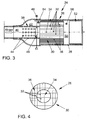
- a catalyst unit 24 is further installed, which comprises an exhaust aftertreatment component 26 according to the invention and hereinafter with reference to FIGS. 2 to 4 is explained in more detail.
- the catalyst unit 24 in the present example a common catalyst housing 28, in which the exhaust aftertreatment component 26 is shock-absorbing, for example, in a so-called Blähmatte stored.
- the exhaust aftertreatment component 26 has a carrier body 30, which is manufactured in one piece from a ceramic material and in the longitudinal direction (see exhaust arrow) has a plurality of flow channels 32, which are formed between thin ceramic walls.
- the known ceramic materials customary for exhaust gas components come into question.
- the carrier body 30 has an inner region 34 and an outer region 36 enclosing the inner region 34 along its radial circumference. Indoor and External areas differ in their cell density, wherein the outer area 36 is greater than that of the inner area 34, preferably by a factor of 4.
- the (lower) cell density of the inner area in a range of 100 to 225 cpsi, so that in this case gives a cell density for the outdoor area of 400 to 900 cpsi.
- inner area 34 and outer area 36 may have a substantially round or annular cross-sectional shape, although other shapes, for example elliptical are possible. In fact, production-related often results in a non-smooth, but stepped interface between inner and outer area, which follows the dimensions of the flow channels 32.
- the inner region 34 can be arranged centrally (coaxially) or decentrally to the outer region 36.
- At least the flow channels 32, that is to say their cell walls, of the outer region 36 have a coating with HC adsorber function.
- This is typically a zeolite coating, which unburned hydrocarbons HC adsorptive and / or chemisorptive to bind and desorb at elevated temperatures again.
- Such coatings are prepared in a known manner as a suspension (washcoat) of fine ceramic particles, e.g. Alumina, applied.
- Suitable HC adsorbers are known to the person skilled in the art and require no further explanation.
- the outer area 36 is equipped with a particle filter function.
- This filter function is preferably obtained by flow channels 32 which are closed alternately in the flow direction.
- alternately means that a part of the flow channels 32 are closed on the inlet side and the other part, namely the channels 32 adjacent to the flow channels 32 closed on the inlet side, are closed on the outlet side.
- the exhaust gas entering a flow channel closed on the outlet side is forced to pass through the cell walls in order to pass into an adjacent flow channel closed on the inlet side 32. Particles are retained when penetrating the cell wall.
- the structure of these wall filters is basically known.
- the interior 34 has a coating, such as a zeolite coating, which is also equipped with an exhaust aftertreatment functionality, in particular with a catalytic function, in the present example with the function of a three-way catalyst.
- a coating such as a zeolite coating
- an exhaust aftertreatment functionality in particular with a catalytic function, in the present example with the function of a three-way catalyst.
- the inner region 34 may also be formed without a coating, so that it itself has no exhaust aftertreatment functionality. In this case, the inner region 34 only serves to allow a bypass line to bypass the HC adsorber of the outer region 36 and to stabilize the carrier body 30 as a whole.
- a concentric inner tube 38 is arranged in an input-side portion of the catalyst housing 28, so that the exhaust path splits in this section into two parallel exhaust pipes, namely an inner main line 40 and an annular, the main line 40 enveloping secondary line 42nd Die mecanicrohr 38 closes with its downstream end to the carrier body 30 of the exhaust gas after-treatment component 26 according to the invention, in particular so that the main line 40 connects to the inner region 34 and the secondary line in the outer region 36.
- the inner tube 38 has a plurality of passage openings 44, which flows through allow the exhaust gas.
- the catalyst unit 24 further has an adjusting means 46 for the selective diversion of the exhaust gas flow into the main line 40 and / or into the secondary line 42.
- the adjusting means 46 is configured in the present example as a rotatably mounted on an axis flap, which is arranged in the inner tube 38 and can be moved between an open position and a closed position by a suitable actuator 48. In the closed position, the flap closes access to the interior region 34 of the exhaust aftertreatment component 26 so that the exhaust stream flows through the openings 44 of the inner tube 38 into the bypass 42 and thus into the outer region 36 and over the HC adsorber. In the open position, however, both the main line 40 and the secondary line 42 are open.
- the exhaust gas stream flows at least largely through the inner region 34 and the exhaust gas catalytic converter present there.
- the adjusting means 46 is also switchable in intermediate positions, so that the exhaust gas flow can be proportionally directed into the main line 40 and into the secondary line 42.
- the means for selectively conducting the exhaust gas into the regions 34 and 36 of the component 26 may also be configured differently than illustrated here by way of example.
- a main catalyst 52 Downstream of the exhaust aftertreatment component 26, the exhaust gas flows into a common exhaust conduit 50 where a main catalyst 52 is arranged which in particular has a three-way catalytic coating and thus serves for the conversion of unburned hydrocarbons HC, carbon monoxide CO and nitrogen oxides NO x .
- temperature sensors 54, 56 may be arranged.
- the sensors 54, 56 measure the exhaust gas temperature and thus allow conclusions about the temperatures of the HC adsorber in the outer region 36 and the main catalytic converter 52. It is also conceivable to install the temperature sensors directly in the corresponding components.
- FIG. 3 shown embodiment of the catalyst unit 24 differs from the after FIG. 2 only in a longer version of the inner tube 38, which projects beyond the inlet port of the housing 28 axially here.
- the inner tube 38 may be connected, for example by a weld with the front edge of the inlet nozzle.
- the embodiment shown here has compared to FIG. 2 essentially manufacturing advantages.
- the in the FIGS. 1 to 3 shown exhaust system 10 shows the following function.
- the actuating means 46 is first closed before the inner region 34 of the component 26, so that the entire exhaust gas flow through the HC adsorber of the outer region 36 flows. This stores the hydrocarbons contained in the exhaust gas, which happen in the first seconds after engine start the non-operational precatalyst 16 unconverted.
- the size of the adsorber is designed so that the hydrocarbons can be stored completely until the precatalyst 16 has reached its light-off temperature and takes over their conversion.
- the actuating means 46 is opened, so that the hot exhaust gas over the interior 34 of the exhaust aftertreatment component 26th existing catalytic converter flows and heats this.
- the exhaust gas catalyst of the inner region 34 reaches its light-off temperature, its further heating accelerates due to the exothermic nature of the conversion reactions.
- the thus already heated exhaust gas flows into the main catalyst 52 and leads to its heating.
- the actuating means 46 is partially or completely closed again, so that the entire or a certain proportion of the exhaust gas flow is led through the HC adsorber and heats it. Once the HC adsorber has reached its desorption temperature, the stored hydrocarbons are released and flow into the common exhaust conduit 50 and into the main catalyst 452 where they are converted to CO 2 and H 2 O.
- the arrangement of the catalytic converter in the inner region 34 significantly accelerates the heating of the downstream main catalytic converter 52 and its starting after a cold start.
- the volumes and / or noble metal loadings of the exhaust catalyst of the inner region 34 and the main catalytic converter 52 and, if provided, the pre-catalytic converter 16 are designed such that the sum of their conversion powers over the entire engine operating map satisfies a predetermined, sufficient and high overall conversion performance. This means that even in corresponding high-speed phases of the drive cycle, the limited exhaust gas components must be converted at least according to the specifications.
- the main catalyst 52 in the desorption phase of the HC adsorber must be able to react the desorbed hydrocarbons. This allows the main catalytic converter 52 to be dimensioned smaller than an analogous system in which no internal catalytic converter 34 is provided, since the internal catalytic converter 34 provides an additional surface with catalytic activity.
- the main catalytic converter 52 can be dimensioned so that it only converts the hydrocarbons released in the desorption phase. In this case, a pure oxidation function of the main catalyst 52 may be sufficient.
Landscapes
- Engineering & Computer Science (AREA)
- Chemical & Material Sciences (AREA)
- Combustion & Propulsion (AREA)
- General Engineering & Computer Science (AREA)
- Mechanical Engineering (AREA)
- Chemical Kinetics & Catalysis (AREA)
- Toxicology (AREA)
- Health & Medical Sciences (AREA)
- Ceramic Engineering (AREA)
- Materials Engineering (AREA)
- Analytical Chemistry (AREA)
- General Chemical & Material Sciences (AREA)
- Oil, Petroleum & Natural Gas (AREA)
- Exhaust Gas After Treatment (AREA)
Claims (11)
- Composant de post-traitement de gaz d'échappement (26) comprenant un corps de support céramique (30) avec une pluralité de canaux d'écoulement axiaux (32), le corps de support (30) présentant une région intérieure (34) et une région extérieure (36) entourant radialement la région intérieure (34) et une densité de cellules du corps de support (30) dans la région intérieure (34) étant inférieure à une densité de cellules dans la région extérieure (36), et au moins la région extérieure (36) du corps de support (30) présentant un revêtement et le revêtement de la région extérieure (36) présentant une fonction d'adsorption des hydrocarbures pour l'adsorption réversible des hydrocarbures (HC) non brûlés, caractérisé en ce que la région extérieure (36) est réalisée sous forme de filtre de courant de paroi et présente de ce fait en outre une fonction de filtre à particules.
- Composant de post-traitement de gaz d'échappement (26) selon la revendication 1, dans lequel le corps de support (30) est réalisé d'une seule pièce.
- Composant de post-traitement de gaz d'échappement (26) selon l'une quelconque des revendications 1 à 2, dans lequel la région intérieure (34) ne présente aucun revêtement.
- Composant de post-traitement de gaz d'échappement (26) selon l'une quelconque des revendications 1 et 2, dans lequel la région intérieure (34) présente un revêtement ayant une fonction catalytique, en particulier une fonction catalytique à trois voies.
- Composant de post-traitement de gaz d'échappement (26) selon l'une quelconque des revendications précédentes, dans lequel un rapport de la densité de cellules de la région extérieure (36) à la densité de cellules de la région intérieure (34) est de 2, 4, 6, 8, 9 ou 12, en particulier de 2, 4 ou 6, de préférence de 4.
- Composant de post-traitement de gaz d'échappement (26) selon l'une quelconque des revendications précédentes, dans lequel la densité de cellules de la région intérieure (34) est comprise dans une plage de 100 à 225 cpsi, en particulier dans une plage de 150 à 200 cpsi.
- Composant de post-traitement de gaz d'échappement (26) selon l'une quelconque des revendications précédentes, comprenant en outre des moyens de réglage (38, 46) pour guider de manière sélective un flux de gaz d'échappement dans la région intérieure (34) et/ou dans la région extérieure (36) du composant de post-traitement de gaz d'échappement (26).
- Installation de gaz d'échappement (10) pour un moteur à combustion interne, comprenant un composant de post-traitement de gaz d'échappement (26) selon l'une quelconque des revendications précédentes 1 à 7.
- Installation de gaz d'échappement (10) selon la revendication 8, comprenant en outre un précatalyseur (16), en particulier un catalyseur à trois voies monté en amont du composant de post-traitement de gaz d'échappement (26) dans la direction d'écoulement du gaz d'échappement.
- Installation de gaz d'échappement (10) selon la revendication 8 ou 9, comprenant en outre un catalyseur principal (52), en particulier un catalyseur à trois voies monté en aval du composant de post-traitement de gaz d'échappement (26) dans la direction d'écoulement de gaz d'échappement.
- Véhicule comprenant un moteur à combustion interne et une installation de gaz d'échappement (10) selon l'une quelconque des revendications 8 à 10, raccordée à celui-ci.
Applications Claiming Priority (2)
| Application Number | Priority Date | Filing Date | Title |
|---|---|---|---|
| DE102012004924A DE102012004924A1 (de) | 2012-03-10 | 2012-03-10 | Abgasnachbehandlungskomponente mit HC-Adsorberfunktion sowie Abgasanlage mit einer solchen |
| PCT/EP2013/052546 WO2013135441A1 (fr) | 2012-03-10 | 2013-02-08 | Composant de post-traitement des gaz d'échappement présentant une fonction d'adsorption des hydrocarbures et système d'échappement pourvu d'un tel composant |
Publications (2)
| Publication Number | Publication Date |
|---|---|
| EP2823162A1 EP2823162A1 (fr) | 2015-01-14 |
| EP2823162B1 true EP2823162B1 (fr) | 2016-10-12 |
Family
ID=47683731
Family Applications (1)
| Application Number | Title | Priority Date | Filing Date |
|---|---|---|---|
| EP13703579.6A Not-in-force EP2823162B1 (fr) | 2012-03-10 | 2013-02-08 | Composant de post-traitement des gaz d'échappement présentant une fonction d'adsorption des hydrocarbures et système d'échappement pourvu d'un tel composant |
Country Status (5)
| Country | Link |
|---|---|
| US (1) | US9567887B2 (fr) |
| EP (1) | EP2823162B1 (fr) |
| CN (1) | CN104145094B (fr) |
| DE (1) | DE102012004924A1 (fr) |
| WO (1) | WO2013135441A1 (fr) |
Families Citing this family (4)
| Publication number | Priority date | Publication date | Assignee | Title |
|---|---|---|---|---|
| CN107762592A (zh) * | 2017-09-29 | 2018-03-06 | 利辛县雨若信息科技有限公司 | 一种新型汽车三元催化器 |
| DE102018104140A1 (de) | 2018-02-23 | 2019-08-29 | Volkswagen Aktiengesellschaft | Partikelfilter für einen Verbrennungsmotor sowie Verfahren zur Herstellung eines solchen Partikelfilters |
| DE102020201008A1 (de) * | 2020-01-28 | 2021-07-29 | Vitesco Technologies GmbH | Vorrichtung zur Abgasnachbehandlung |
| CN114483269B (zh) * | 2022-01-26 | 2023-01-31 | 宁波吉利罗佑发动机零部件有限公司 | 一种用于汽车发动机冷启动的排气处理装置及控制方法 |
Family Cites Families (18)
| Publication number | Priority date | Publication date | Assignee | Title |
|---|---|---|---|---|
| JPS55147154A (en) * | 1979-05-07 | 1980-11-15 | Ngk Spark Plug Co Ltd | High-strength honeycomb structure |
| JP3526084B2 (ja) * | 1993-12-28 | 2004-05-10 | 日本碍子株式会社 | 排ガス浄化用吸着・触媒体、吸着体、排ガス浄化システム及び排ガス浄化方法 |
| SE9304371D0 (sv) * | 1993-12-30 | 1993-12-30 | Volvo Ab | An exhaust gas purification device |
| EP0697505A1 (fr) * | 1994-08-02 | 1996-02-21 | Corning Incorporated | Dispositif d'adsorption en ligne |
| US5787707A (en) * | 1994-08-02 | 1998-08-04 | Corning Incorporated | In-line adsorber system |
| US5934069A (en) * | 1995-06-08 | 1999-08-10 | Corning Incorporated | In-line adsorber system |
| US6354076B1 (en) * | 1998-07-16 | 2002-03-12 | Honda Giken Kogyo Kabushiki Kaisha | Exhaust gas purification system of internal combustion engine |
| DE19938038A1 (de) | 1998-09-14 | 2000-05-04 | Ford Global Tech Inc | Abgasbehandlungsvorrichtung mit variierender Zelldichte |
| JP3426580B2 (ja) | 2000-12-15 | 2003-07-14 | 本田技研工業株式会社 | 内燃機関用hc吸着剤 |
| EP1415072B1 (fr) * | 2001-08-08 | 2006-12-13 | Toyota Jidosha Kabushiki Kaisha | Dispositif epurateur de gaz d'echappement |
| DE10201042A1 (de) | 2002-01-14 | 2003-08-07 | Eberspaecher J Gmbh & Co | Abgasanlage für Verbrennungsmotoren, mit einem katalytischen Abgaskonverter |
| JP2003277162A (ja) * | 2002-01-21 | 2003-10-02 | Ngk Insulators Ltd | 多孔質ハニカム構造体、その用途及びその製造方法 |
| JP2003340224A (ja) * | 2002-05-30 | 2003-12-02 | Ngk Insulators Ltd | ハニカム構造体、及びその製造方法 |
| DE102005032954B4 (de) | 2005-07-14 | 2017-10-05 | Emcon Technologies Germany (Augsburg) Gmbh | Partikelfilter für Abgase |
| US8343448B2 (en) | 2008-09-30 | 2013-01-01 | Ford Global Technologies, Llc | System for reducing NOx in exhaust |
| US8940242B2 (en) * | 2009-04-17 | 2015-01-27 | Basf Corporation | Multi-zoned catalyst compositions |
| DE102010056281A1 (de) * | 2010-12-24 | 2012-06-28 | Volkswagen Ag | Abgasanlage mit HC-Adsorber und parallelem Abgaskatalysator sowie Fahrzeug mit einer solchen Abgasanlage |
| DE102012017178A1 (de) * | 2012-03-10 | 2013-09-12 | Volkswagen Aktiengesellschaft | Abgasreinigungsvorrichtung |
-
2012
- 2012-03-10 DE DE102012004924A patent/DE102012004924A1/de not_active Withdrawn
-
2013
- 2013-02-08 WO PCT/EP2013/052546 patent/WO2013135441A1/fr not_active Ceased
- 2013-02-08 CN CN201380013460.1A patent/CN104145094B/zh not_active Expired - Fee Related
- 2013-02-08 EP EP13703579.6A patent/EP2823162B1/fr not_active Not-in-force
-
2014
- 2014-09-07 US US14/479,348 patent/US9567887B2/en active Active
Also Published As
| Publication number | Publication date |
|---|---|
| EP2823162A1 (fr) | 2015-01-14 |
| US9567887B2 (en) | 2017-02-14 |
| US20140373515A1 (en) | 2014-12-25 |
| CN104145094B (zh) | 2017-06-06 |
| DE102012004924A1 (de) | 2013-09-12 |
| WO2013135441A1 (fr) | 2013-09-19 |
| CN104145094A (zh) | 2014-11-12 |
Similar Documents
| Publication | Publication Date | Title |
|---|---|---|
| EP2655820B1 (fr) | Système d'échappement avec adsorbeur d'hydrocarbures et catalyseur de gaz d'échappement parallèle ainsi que véhicule équipé d'un tel système d'échappement | |
| EP2710239B1 (fr) | Systeme d'échappement avec piège hc et catalyseur en parallel et vehicule équipé d'un tel systeme | |
| DE102010026888B4 (de) | Abgasbehandlungssystem mit einem Aschefilter und Verfahren zum Behandeln einer Abgasströmung | |
| EP1440226B1 (fr) | Filtre particulaire ouvert muni d'un element chauffant | |
| EP1379322B2 (fr) | Systeme d'echappement | |
| EP2310113B1 (fr) | Système d'épuration de gaz d'échappement pour des moteurs diesel de véhicules utilitaires | |
| EP1625286A1 (fr) | Regeneration d'un piege a particules | |
| WO2014079664A1 (fr) | Dispositif de post-traitement des gaz d'échappement à réduction catalytique sélective et véhicule automobile pourvu d'un tel dispositif | |
| DE102010055147A1 (de) | Vier-Wege-Katalysator, seine Verwendung sowie Fahrzeug mit einem solchen | |
| EP1747356B1 (fr) | Corps support de catalyseur destine a un convertisseur catalytique employe a proximite du moteur | |
| DE102005005663A1 (de) | Abgasnachbehandlungseinrichtung mit Partikelfilter | |
| WO2015161960A1 (fr) | Sous-ensemble catalyseur, sous-ensemble contenant un dispositif d'épuration des gaz d'échappement d'un moteur à combustion interne, système modulaire pour le sous-ensemble, et procédé de fabrication du sous-ensemble | |
| EP2823162B1 (fr) | Composant de post-traitement des gaz d'échappement présentant une fonction d'adsorption des hydrocarbures et système d'échappement pourvu d'un tel composant | |
| EP3990757A1 (fr) | Dispositif de post-traitement de gaz d'échappement | |
| WO2015150153A2 (fr) | Procédé de régénération pour des systèmes de post-traitement des gaz d'échappement | |
| EP2659950B1 (fr) | Système de traitement postérieur de gaz d'échappement | |
| DE102007036254A1 (de) | Abgasanlage einer Brennkraftmaschine | |
| WO2004113694A1 (fr) | Composant catalyseur et systeme de gaz d'echappement | |
| EP1541820A2 (fr) | Moteur à combustion interne avec un dispositif de purification des gaz d'échappement et procédé d'opération d'un moteur à combustion interne | |
| DE102008031657A1 (de) | Abgaskonverter zur katalytischen Nachbehandlung verbrennungsmotorischer Abgase sowie Abgasanlage enthaltend einen solchen | |
| EP1511556B1 (fr) | Systeme catalyseur | |
| DE10357887A1 (de) | Brennkraftmaschine mit einer Abgasreinigungsvorrichtung und Verfahren zum Betrieb einer Brennkraftmaschine |
Legal Events
| Date | Code | Title | Description |
|---|---|---|---|
| PUAI | Public reference made under article 153(3) epc to a published international application that has entered the european phase |
Free format text: ORIGINAL CODE: 0009012 |
|
| 17P | Request for examination filed |
Effective date: 20141010 |
|
| AK | Designated contracting states |
Kind code of ref document: A1 Designated state(s): AL AT BE BG CH CY CZ DE DK EE ES FI FR GB GR HR HU IE IS IT LI LT LU LV MC MK MT NL NO PL PT RO RS SE SI SK SM TR |
|
| AX | Request for extension of the european patent |
Extension state: BA ME |
|
| DAX | Request for extension of the european patent (deleted) | ||
| GRAP | Despatch of communication of intention to grant a patent |
Free format text: ORIGINAL CODE: EPIDOSNIGR1 |
|
| INTG | Intention to grant announced |
Effective date: 20160608 |
|
| GRAS | Grant fee paid |
Free format text: ORIGINAL CODE: EPIDOSNIGR3 |
|
| GRAA | (expected) grant |
Free format text: ORIGINAL CODE: 0009210 |
|
| AK | Designated contracting states |
Kind code of ref document: B1 Designated state(s): AL AT BE BG CH CY CZ DE DK EE ES FI FR GB GR HR HU IE IS IT LI LT LU LV MC MK MT NL NO PL PT RO RS SE SI SK SM TR |
|
| REG | Reference to a national code |
Ref country code: GB Ref legal event code: FG4D Free format text: NOT ENGLISH |
|
| REG | Reference to a national code |
Ref country code: CH Ref legal event code: EP |
|
| REG | Reference to a national code |
Ref country code: AT Ref legal event code: REF Ref document number: 836723 Country of ref document: AT Kind code of ref document: T Effective date: 20161015 |
|
| REG | Reference to a national code |
Ref country code: IE Ref legal event code: FG4D Free format text: LANGUAGE OF EP DOCUMENT: GERMAN |
|
| REG | Reference to a national code |
Ref country code: DE Ref legal event code: R096 Ref document number: 502013004946 Country of ref document: DE |
|
| REG | Reference to a national code |
Ref country code: LT Ref legal event code: MG4D |
|
| REG | Reference to a national code |
Ref country code: NL Ref legal event code: MP Effective date: 20161012 |
|
| REG | Reference to a national code |
Ref country code: FR Ref legal event code: PLFP Year of fee payment: 5 |
|
| PG25 | Lapsed in a contracting state [announced via postgrant information from national office to epo] |
Ref country code: LV Free format text: LAPSE BECAUSE OF FAILURE TO SUBMIT A TRANSLATION OF THE DESCRIPTION OR TO PAY THE FEE WITHIN THE PRESCRIBED TIME-LIMIT Effective date: 20161012 |
|
| PG25 | Lapsed in a contracting state [announced via postgrant information from national office to epo] |
Ref country code: LT Free format text: LAPSE BECAUSE OF FAILURE TO SUBMIT A TRANSLATION OF THE DESCRIPTION OR TO PAY THE FEE WITHIN THE PRESCRIBED TIME-LIMIT Effective date: 20161012 Ref country code: NO Free format text: LAPSE BECAUSE OF FAILURE TO SUBMIT A TRANSLATION OF THE DESCRIPTION OR TO PAY THE FEE WITHIN THE PRESCRIBED TIME-LIMIT Effective date: 20170112 Ref country code: SE Free format text: LAPSE BECAUSE OF FAILURE TO SUBMIT A TRANSLATION OF THE DESCRIPTION OR TO PAY THE FEE WITHIN THE PRESCRIBED TIME-LIMIT Effective date: 20161012 Ref country code: GR Free format text: LAPSE BECAUSE OF FAILURE TO SUBMIT A TRANSLATION OF THE DESCRIPTION OR TO PAY THE FEE WITHIN THE PRESCRIBED TIME-LIMIT Effective date: 20170113 |
|
| PG25 | Lapsed in a contracting state [announced via postgrant information from national office to epo] |
Ref country code: RS Free format text: LAPSE BECAUSE OF FAILURE TO SUBMIT A TRANSLATION OF THE DESCRIPTION OR TO PAY THE FEE WITHIN THE PRESCRIBED TIME-LIMIT Effective date: 20161012 Ref country code: NL Free format text: LAPSE BECAUSE OF FAILURE TO SUBMIT A TRANSLATION OF THE DESCRIPTION OR TO PAY THE FEE WITHIN THE PRESCRIBED TIME-LIMIT Effective date: 20161012 Ref country code: FI Free format text: LAPSE BECAUSE OF FAILURE TO SUBMIT A TRANSLATION OF THE DESCRIPTION OR TO PAY THE FEE WITHIN THE PRESCRIBED TIME-LIMIT Effective date: 20161012 Ref country code: ES Free format text: LAPSE BECAUSE OF FAILURE TO SUBMIT A TRANSLATION OF THE DESCRIPTION OR TO PAY THE FEE WITHIN THE PRESCRIBED TIME-LIMIT Effective date: 20161012 Ref country code: PL Free format text: LAPSE BECAUSE OF FAILURE TO SUBMIT A TRANSLATION OF THE DESCRIPTION OR TO PAY THE FEE WITHIN THE PRESCRIBED TIME-LIMIT Effective date: 20161012 Ref country code: HR Free format text: LAPSE BECAUSE OF FAILURE TO SUBMIT A TRANSLATION OF THE DESCRIPTION OR TO PAY THE FEE WITHIN THE PRESCRIBED TIME-LIMIT Effective date: 20161012 Ref country code: BE Free format text: LAPSE BECAUSE OF NON-PAYMENT OF DUE FEES Effective date: 20170228 Ref country code: PT Free format text: LAPSE BECAUSE OF FAILURE TO SUBMIT A TRANSLATION OF THE DESCRIPTION OR TO PAY THE FEE WITHIN THE PRESCRIBED TIME-LIMIT Effective date: 20170213 Ref country code: IS Free format text: LAPSE BECAUSE OF FAILURE TO SUBMIT A TRANSLATION OF THE DESCRIPTION OR TO PAY THE FEE WITHIN THE PRESCRIBED TIME-LIMIT Effective date: 20170212 |
|
| REG | Reference to a national code |
Ref country code: DE Ref legal event code: R097 Ref document number: 502013004946 Country of ref document: DE |
|
| PG25 | Lapsed in a contracting state [announced via postgrant information from national office to epo] |
Ref country code: CZ Free format text: LAPSE BECAUSE OF FAILURE TO SUBMIT A TRANSLATION OF THE DESCRIPTION OR TO PAY THE FEE WITHIN THE PRESCRIBED TIME-LIMIT Effective date: 20161012 Ref country code: EE Free format text: LAPSE BECAUSE OF FAILURE TO SUBMIT A TRANSLATION OF THE DESCRIPTION OR TO PAY THE FEE WITHIN THE PRESCRIBED TIME-LIMIT Effective date: 20161012 Ref country code: DK Free format text: LAPSE BECAUSE OF FAILURE TO SUBMIT A TRANSLATION OF THE DESCRIPTION OR TO PAY THE FEE WITHIN THE PRESCRIBED TIME-LIMIT Effective date: 20161012 Ref country code: RO Free format text: LAPSE BECAUSE OF FAILURE TO SUBMIT A TRANSLATION OF THE DESCRIPTION OR TO PAY THE FEE WITHIN THE PRESCRIBED TIME-LIMIT Effective date: 20161012 Ref country code: SK Free format text: LAPSE BECAUSE OF FAILURE TO SUBMIT A TRANSLATION OF THE DESCRIPTION OR TO PAY THE FEE WITHIN THE PRESCRIBED TIME-LIMIT Effective date: 20161012 |
|
| PLBE | No opposition filed within time limit |
Free format text: ORIGINAL CODE: 0009261 |
|
| STAA | Information on the status of an ep patent application or granted ep patent |
Free format text: STATUS: NO OPPOSITION FILED WITHIN TIME LIMIT |
|
| PG25 | Lapsed in a contracting state [announced via postgrant information from national office to epo] |
Ref country code: SM Free format text: LAPSE BECAUSE OF FAILURE TO SUBMIT A TRANSLATION OF THE DESCRIPTION OR TO PAY THE FEE WITHIN THE PRESCRIBED TIME-LIMIT Effective date: 20161012 Ref country code: IT Free format text: LAPSE BECAUSE OF FAILURE TO SUBMIT A TRANSLATION OF THE DESCRIPTION OR TO PAY THE FEE WITHIN THE PRESCRIBED TIME-LIMIT Effective date: 20161012 Ref country code: BG Free format text: LAPSE BECAUSE OF FAILURE TO SUBMIT A TRANSLATION OF THE DESCRIPTION OR TO PAY THE FEE WITHIN THE PRESCRIBED TIME-LIMIT Effective date: 20170112 |
|
| 26N | No opposition filed |
Effective date: 20170713 |
|
| PG25 | Lapsed in a contracting state [announced via postgrant information from national office to epo] |
Ref country code: MC Free format text: LAPSE BECAUSE OF FAILURE TO SUBMIT A TRANSLATION OF THE DESCRIPTION OR TO PAY THE FEE WITHIN THE PRESCRIBED TIME-LIMIT Effective date: 20161012 |
|
| REG | Reference to a national code |
Ref country code: CH Ref legal event code: PL |
|
| PG25 | Lapsed in a contracting state [announced via postgrant information from national office to epo] |
Ref country code: LI Free format text: LAPSE BECAUSE OF NON-PAYMENT OF DUE FEES Effective date: 20170228 Ref country code: CH Free format text: LAPSE BECAUSE OF NON-PAYMENT OF DUE FEES Effective date: 20170228 |
|
| REG | Reference to a national code |
Ref country code: IE Ref legal event code: MM4A |
|
| PG25 | Lapsed in a contracting state [announced via postgrant information from national office to epo] |
Ref country code: SI Free format text: LAPSE BECAUSE OF FAILURE TO SUBMIT A TRANSLATION OF THE DESCRIPTION OR TO PAY THE FEE WITHIN THE PRESCRIBED TIME-LIMIT Effective date: 20161012 |
|
| PG25 | Lapsed in a contracting state [announced via postgrant information from national office to epo] |
Ref country code: LU Free format text: LAPSE BECAUSE OF NON-PAYMENT OF DUE FEES Effective date: 20170208 |
|
| REG | Reference to a national code |
Ref country code: BE Ref legal event code: MM Effective date: 20170228 |
|
| REG | Reference to a national code |
Ref country code: FR Ref legal event code: PLFP Year of fee payment: 6 |
|
| PG25 | Lapsed in a contracting state [announced via postgrant information from national office to epo] |
Ref country code: IE Free format text: LAPSE BECAUSE OF NON-PAYMENT OF DUE FEES Effective date: 20170208 |
|
| PG25 | Lapsed in a contracting state [announced via postgrant information from national office to epo] |
Ref country code: MT Free format text: LAPSE BECAUSE OF FAILURE TO SUBMIT A TRANSLATION OF THE DESCRIPTION OR TO PAY THE FEE WITHIN THE PRESCRIBED TIME-LIMIT Effective date: 20161012 |
|
| REG | Reference to a national code |
Ref country code: AT Ref legal event code: MM01 Ref document number: 836723 Country of ref document: AT Kind code of ref document: T Effective date: 20180208 |
|
| PG25 | Lapsed in a contracting state [announced via postgrant information from national office to epo] |
Ref country code: AT Free format text: LAPSE BECAUSE OF NON-PAYMENT OF DUE FEES Effective date: 20180208 |
|
| PG25 | Lapsed in a contracting state [announced via postgrant information from national office to epo] |
Ref country code: HU Free format text: LAPSE BECAUSE OF FAILURE TO SUBMIT A TRANSLATION OF THE DESCRIPTION OR TO PAY THE FEE WITHIN THE PRESCRIBED TIME-LIMIT; INVALID AB INITIO Effective date: 20130208 |
|
| PG25 | Lapsed in a contracting state [announced via postgrant information from national office to epo] |
Ref country code: CY Free format text: LAPSE BECAUSE OF FAILURE TO SUBMIT A TRANSLATION OF THE DESCRIPTION OR TO PAY THE FEE WITHIN THE PRESCRIBED TIME-LIMIT Effective date: 20161012 |
|
| PG25 | Lapsed in a contracting state [announced via postgrant information from national office to epo] |
Ref country code: MK Free format text: LAPSE BECAUSE OF FAILURE TO SUBMIT A TRANSLATION OF THE DESCRIPTION OR TO PAY THE FEE WITHIN THE PRESCRIBED TIME-LIMIT Effective date: 20161012 |
|
| PG25 | Lapsed in a contracting state [announced via postgrant information from national office to epo] |
Ref country code: TR Free format text: LAPSE BECAUSE OF FAILURE TO SUBMIT A TRANSLATION OF THE DESCRIPTION OR TO PAY THE FEE WITHIN THE PRESCRIBED TIME-LIMIT Effective date: 20161012 |
|
| PG25 | Lapsed in a contracting state [announced via postgrant information from national office to epo] |
Ref country code: AL Free format text: LAPSE BECAUSE OF FAILURE TO SUBMIT A TRANSLATION OF THE DESCRIPTION OR TO PAY THE FEE WITHIN THE PRESCRIBED TIME-LIMIT Effective date: 20161012 |
|
| P01 | Opt-out of the competence of the unified patent court (upc) registered |
Effective date: 20230523 |
|
| PGFP | Annual fee paid to national office [announced via postgrant information from national office to epo] |
Ref country code: DE Payment date: 20240229 Year of fee payment: 12 Ref country code: GB Payment date: 20240220 Year of fee payment: 12 |
|
| PGFP | Annual fee paid to national office [announced via postgrant information from national office to epo] |
Ref country code: FR Payment date: 20240226 Year of fee payment: 12 |
|
| REG | Reference to a national code |
Ref country code: DE Ref legal event code: R119 Ref document number: 502013004946 Country of ref document: DE |
|
| GBPC | Gb: european patent ceased through non-payment of renewal fee |
Effective date: 20250208 |
|
| PG25 | Lapsed in a contracting state [announced via postgrant information from national office to epo] |
Ref country code: DE Free format text: LAPSE BECAUSE OF NON-PAYMENT OF DUE FEES Effective date: 20250902 |
|
| PG25 | Lapsed in a contracting state [announced via postgrant information from national office to epo] |
Ref country code: GB Free format text: LAPSE BECAUSE OF NON-PAYMENT OF DUE FEES Effective date: 20250208 |
|
| PG25 | Lapsed in a contracting state [announced via postgrant information from national office to epo] |
Ref country code: FR Free format text: LAPSE BECAUSE OF NON-PAYMENT OF DUE FEES Effective date: 20250228 |