EP2823924B2 - Machine à dresser double - Google Patents
Machine à dresser double Download PDFInfo
- Publication number
- EP2823924B2 EP2823924B2 EP14171795.9A EP14171795A EP2823924B2 EP 2823924 B2 EP2823924 B2 EP 2823924B2 EP 14171795 A EP14171795 A EP 14171795A EP 2823924 B2 EP2823924 B2 EP 2823924B2
- Authority
- EP
- European Patent Office
- Prior art keywords
- tool
- grinding
- dressing
- tools
- accordance
- Prior art date
- Legal status (The legal status is an assumption and is not a legal conclusion. Google has not performed a legal analysis and makes no representation as to the accuracy of the status listed.)
- Active
Links
Images


Classifications
-
- B—PERFORMING OPERATIONS; TRANSPORTING
- B24—GRINDING; POLISHING
- B24B—MACHINES, DEVICES, OR PROCESSES FOR GRINDING OR POLISHING; DRESSING OR CONDITIONING OF ABRADING SURFACES; FEEDING OF GRINDING, POLISHING, OR LAPPING AGENTS
- B24B53/00—Devices or means for dressing or conditioning abrasive surfaces
- B24B53/06—Devices or means for dressing or conditioning abrasive surfaces of profiled abrasive wheels
- B24B53/075—Devices or means for dressing or conditioning abrasive surfaces of profiled abrasive wheels for workpieces having a grooved profile, e.g. gears, splined shafts, threads, worms
-
- B—PERFORMING OPERATIONS; TRANSPORTING
- B23—MACHINE TOOLS; METAL-WORKING NOT OTHERWISE PROVIDED FOR
- B23F—MAKING GEARS OR TOOTHED RACKS
- B23F21/00—Tools specially adapted for use in machines for manufacturing gear teeth
- B23F21/005—Tools specially adapted for use in machines for manufacturing gear teeth with plural tools on a common axis
-
- B—PERFORMING OPERATIONS; TRANSPORTING
- B23—MACHINE TOOLS; METAL-WORKING NOT OTHERWISE PROVIDED FOR
- B23F—MAKING GEARS OR TOOTHED RACKS
- B23F21/00—Tools specially adapted for use in machines for manufacturing gear teeth
- B23F21/02—Grinding discs; Grinding worms
- B23F21/026—Grinding worms
-
- B—PERFORMING OPERATIONS; TRANSPORTING
- B23—MACHINE TOOLS; METAL-WORKING NOT OTHERWISE PROVIDED FOR
- B23F—MAKING GEARS OR TOOTHED RACKS
- B23F23/00—Accessories or equipment combined with or arranged in, or specially designed to form part of, gear-cutting machines
- B23F23/12—Other devices, e.g. tool holders; Checking devices for controlling workpieces in machines for manufacturing gear teeth
- B23F23/1225—Arrangements of abrasive wheel dressing devices on gear-cutting machines
-
- B—PERFORMING OPERATIONS; TRANSPORTING
- B24—GRINDING; POLISHING
- B24B—MACHINES, DEVICES, OR PROCESSES FOR GRINDING OR POLISHING; DRESSING OR CONDITIONING OF ABRADING SURFACES; FEEDING OF GRINDING, POLISHING, OR LAPPING AGENTS
- B24B53/00—Devices or means for dressing or conditioning abrasive surfaces
- B24B53/06—Devices or means for dressing or conditioning abrasive surfaces of profiled abrasive wheels
- B24B53/062—Devices or means for dressing or conditioning abrasive surfaces of profiled abrasive wheels using rotary dressing tools
Definitions
- the invention relates to a device and a method for dressing roller or profile grinding tools for the gear machining of toothed workpieces with at least two disk-shaped dressing tools with which one or more tool areas and/or profile areas of the tool are provided with a defined dressing geometry, as well as a gear cutting machine with such a device and a control program for the automated implementation of the said method.
- Gear grinding machines are used in the manufacture of gears for hard finishing of pre-machined gears in order to give them their final geometry.
- teeth are first formed from a rotationally symmetrical workpiece in a soft pre-machining step, e.g. by milling or shaping.
- the workpiece pre-machined in this way is then subjected to heat treatment, which hardens at least the areas of the gear near the surface of the teeth.
- heat treatment is carried out on the gear grinding machine.
- a grinding wheel and/or a grinding worm is used to machine the workpiece and give it its final geometry.
- the grinding wheel or grinding worm In order to adapt the grinding wheels or grinding worms to the desired geometry of the gear and/or to compensate for the wear of a grinding wheel and/or grinding worm, the grinding wheel or grinding worm must be dressed at regular intervals during operation to adjust to a new geometry of the workpiece.
- Dressing or profiling a grinding wheel and/or grinding worm includes the actual profiling, i.e. generating the required geometry of the grinding wheel and/or grinding worm (concentricity, cylindricity, profile), and sharpening, i.e. creating a grinding surface that cuts well (microgeometry).
- the term dressing is often used for creating a geometry and restoring a grinding surface that cuts well.
- profiling grinding wheels and grinding worms different profiling tools are used depending on the required boundary conditions such as dressing unit, tool type (worm, wheel) or required profile corrections. A distinction is also made as to whether the entire profile (profile dressing) or only parts of it (form dressing) are dressed.
- the dressing wheel is moved along the surface of the tool in a path-controlled manner and in the process dresses the grinding tool. There is limited contact between the dressing tool and the grinding tool. When dressing grinding worms, a large number of dressing strokes are therefore necessary, between which the dressing tool is fed a certain amount so that the entire surface of the grinding tool is dressed. This makes the dressing process very flexible in terms of modifications, but it takes a long time, since only small areas of the tool are dressed at a time.
- the dressing process is significantly faster because the entire profile is always dressed. There is line contact over the entire profile height of the grinding tool. This means that changes to the profile are only possible by changing the dressing tool.
- the profiling time is very short because one or both flanks of a worm thread are fully dressed with one dressing stroke of the grinding tool, depending on whether one or both flanks are being dressed. If necessary, the profile flanks can be profiled differently from one another and variably across the width of the worm in order to create a so-called three-dimensionally modified grinding worm. In some cases, the tooth tip and the tooth flanks are also dressed separately during profile dressing. There are special flank and tip dressing wheels for this purpose.
- the head and profile dressing processes are to be carried out at different frequencies or if several different gears with different profiles are to be machined with a grinding tool in one work process, several dressing tools must be present in the machine at the same time. However, these must be mounted in such a way that they do not influence each other. This must also be guaranteed if the dressing tool is to be swiveled in different ways in order to modify the pressure angle of the gear.
- a diamond disk device is disclosed as a double dresser with two motors, each for independently driving two dressing diamond disks.
- the tool holders of the two dressing motors face each other.
- the tool holders are designed to hold diamond disks with which one flank of a grinding worm is dressed.
- This type of dressing disk is shown in the illustration Fig. 2 , tool 8b.
- the engagement state of the dressing wheels with the grinding worm is shown.
- the DE 10 2011120449 A1 relates to a method for grinding a toothed workpiece having a gear axis in at least two operations, in which in a first operation a grinding area of a grinding tool determined by the grinding process, rotating about a rotation axis and fed in the direction of the axis distance between the gear axis and the rotation axis is brought into grinding engagement with a tooth flank of the workpiece, and the tooth flank is brought into grinding engagement in a subsequent second operation with a grinding area of a grinding tool determined by the grinding process and fed in the feed direction of the first operation, wherein the grinding area grinding in the first operation is dressed by a first dressing with a dressing tool and the grinding area grinding in the second operation is dressed by a second dressing with a dressing tool, wherein during the first dressing a first dressing area and during the second dressing a second dressing area spatially separated from the first dressing area is brought into dressing engagement with the respective grinding area.
- a one-piece, electroplated tool with two different areas is disclosed. These two areas are coated with hard materials in order to take on different grinding tasks during the hard finishing process.
- the grinding tool has a conical holder sleeve with which it is mounted and clamped onto a tool base mandrel.
- a tool in this embodiment can also be designed in such a way that workpieces with two different toothings can be machined according to the invention. Due to the electroplated coating, however, this tool cannot be flexibly adapted to the machining task, as would be the case with a dressable tool.
- the DE 10 2004 020 364 A1 describes a tool for generating gear grinding with a multi-part grinding tool with dressable grinding wheels.
- a multi-part tool is described here in which different types of grinding wheels are clamped onto a common base mandrel.
- the different types of grinding wheels are used in this application to carry out the roughing and finishing processes when grinding a gear with an optimized grinding coating and thus to obtain the best possible machining process.
- the application to different gears is not mentioned.
- the distance between the two tools must be set exactly to the gear teeth when both dressing tools are engaged, otherwise the grinding worm will be damaged. Only the head dresser can be moved perpendicular to the tool axis and in the axial direction of the dresser using a cross slide. This means that the head and foot dresser can only be used in addition to the flank dresser. Dressing two different gear teeth is not possible with this arrangement.
- the dressing tool as it is DE 196 24 842 A1 disclosed is used for machining partial areas of a grinding tool.
- the flanks of the dressing tool are dressed in line contact with the flanks of the dressing tool.
- the head of the dressing tool is used for form dressing of partial areas of a grinding tool.
- the disadvantage of this design is that this tool can only be used to dress two different gears to a limited extent.
- the disadvantage of all previously presented embodiments for dressing wheels is the fact that only the tool for machining one gear can be dressed.
- the other dressing wheels are adapted to the gear geometry of the workpieces to be machined.
- Tool 8a can accommodate almost any grinding wheel or Grinding worm can be machined as long as the geometry of the dressing wheel allows it.
- the disadvantage is the time required for the dressing cycle, since only a part of the grinding tool is machined at a time. This is the case with profile dressers of the Fig.2 , 8b to 8c is not or only partially the case.
- a grinding tool is to be dressed for machining a workpiece with several gear teeth that differ significantly in terms of geometry (e.g. module, tip or root relief, profile crowning, possibly number of teeth, etc.), then the use of two different dressing wheels is necessary if the tool is not to be machined using the line dressing method.
- geometry e.g. module, tip or root relief, profile crowning, possibly number of teeth, etc.
- the outside diameter of these dressing tools usually differs only minimally. If such dressing wheels are to be used, this cannot be done with a state-of-the-art dressing device with two dressing tools facing each other, as otherwise the grinding worm would collide with the dressing tool that is not currently being used when dressing the grinding worm.
- the dressing unit must therefore be designed in such a way that the dressing wheels can be brought into engagement with the grinding tool one after the other without collision.
- the core of the invention is a dressing unit which is suitable for accommodating at least two different dressing tools and for bringing these into engagement independently of one another with an associated grinding tool or tool area during the dressing process, without the dressing processes/dressing tools influencing one another.
- dressing tool also means a combination dressing tool for the simultaneous dressing of tooth tip and tooth flanks, as used, for example, in Fig. 2 , 8c and 8d.
- a dressing unit could be arranged on the counterholder of a grinding machine according to the state of the art as shown in the Fig. 1
- other mounting locations are also conceivable which can be approached with the machining head and/or the dressing device and at which the grinding tools can be brought into engagement with the dressing tools.
- At least one of these holders for the dressing tool is designed to be pivotable about an axis which is at an angle of 10° to 90° to the dressing tool axis, so that changes to the pressure angle of a grinding worm can be made.
- the at least two tool holders can be driven independently of each other around the tool axis in order to set the dressing tool in a rotary motion.
- the grinding tools can be dressed much more flexibly. Furthermore, dressable tools for producing two different gears on one grinding machine can also be dressed more quickly, since there is no need to resort to slow form dressing / line dressing.
- the dressing unit can also be used if the flanks of the grinding tool and the head are to be dressed with different tools at different intervals.
- a combination tool such as the one in Fig. 2 , 8c, 8d is no longer possible.
- the dressing tool for the tool flanks and the head dresser must be designed separately so that these tools can also be used separately.
- a form dresser can be combined with a profile dresser.
- the entire profile of the tool can then be dressed with the profile dresser in a process-time-optimized manner and then small profile areas, such as the tooth foot or the tooth tip, can be modified line by line using the form dressing process. This combination enables very flexible dressing with a short dressing time.
- This dressing unit could also be used to dress a combination tool consisting of at least one grinding worm and at least one grinding wheel or a grinding wheel set tool. This is because the grinding wheel is often shaped and a profile dresser is used for the grinding worm. Thanks to the independent tool holders, these combination grinding tools can also be dressed quickly and flexibly.
- This combination then opens up further new possibilities such as a combination of gear machining with an external cylindrical grinding operation or a machining combination of external and internal gears if the machining head offers this option.
- This dressing unit also includes a dressable grinding tool consisting of one or two grinding worms, a combination of a grinding worm and a grinding wheel, or two grinding wheels or grinding wheel set tools. Depending on the application, the best combination for the respective machining case can be selected.
- the present invention further comprises control software for a gear grinding machine, in particular control software stored in a data memory or on a data carrier with program code for carrying out a method as described above.
- control software advantageously has the corresponding operating modes or operator prompts.
- Figure 1 shows a gear grinding machine 1 according to the prior art on which, for example, a dressing device according to the invention can be used.
- a machine table 7 is mounted on a machine bed 2 and is intended to hold workpieces 6 via a clamping device (not shown).
- the machine table 7 can be rotated about the axis C1, which is advantageously aligned vertically. Alternatively, horizontally aligned machine tables can also be used.
- the gear grinding machine also has a machine stand 3 and a machining head 15 with a work spindle 14 for clamping a tool holder 9.
- a counter support 4 is mounted on the machine bed 2 opposite the machine stand 3.
- a loading system with a swivel axis C3 which transports the workpiece 6 from an external automation system (not shown) onto the machine table 7 or into the clamping device mounted on the machine table.
- a counter support arm 12 can be moved vertically and parallel to the C1 axis via a Z4 axis.
- a dressing unit 10 is attached to the counterholder arm.
- the dressing tool 8 can be moved about a rotation axis B3 and a swivel axis C5.
- the machining head 15 with the tool is moved towards the workpiece via the X1 axis.
- the C1 and B1 axes rotate in a synchronized manner, i.e. with a rolling coupling, while the machining head moves in the Z1 direction and, if necessary, in the X1, V1 direction.
- the machining of the workpiece with the grinding wheel or grinding worm is usually carried out by generating grinding or profile grinding or a combination of these.
- the machining head 15 in this embodiment is moved to the dressing tool 8 via the X1 axis and Z1 axis and is brought into engagement with the dressing tool 8 there.
- the machining head 15 with the machining tool is moved relative to the dressing tool 8 via the X1, Z1, V1 and A1 axes, while the machining tool rotates about the B1 axis.
- the dressing tool 8 itself rotates about its B3 axis and is pivoted about the C5 axis as required, depending on the selected dressing program.
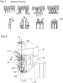
- the Figure 2 shows examples of various types of dressing and profiling tools 8a to 8d for the form and profile dressing of grinding tools, according to the state of the art.
- a form dresser 8a is usually used for dressing grinding wheels or grinding worms in which the dressing wheel with its radius R is guided along the outer contour of the grinding wheel or grinding worm while the two tools rotate. This is often also referred to as line dressing. With the other dressers shown, the tool is dressed over its entire profile height in a dressing process, whereby this can be done on one flank (Fig. 8b, 8c) or both flanks (Fig. 8d).
- the dressing unit according to the invention is primarily intended for use with dressers according to Figs. 8c and 8d, since both tooth flanks of a grinding tool are dressed with one dressing wheel.
- Figure 3 shows a dresser 5,5* according to the invention, here for example for arrangement on the counter-holder arm 12 on the counter-support 4 of a gear cutting machine.
- the two dressing units 5, 5* are arranged one above the other.
- the dressing tools are driven 8,8* with the two motors 11, 11* that rotate the tool around the B3, B3* axis.
- the dressing tools can be rotated around the C5, C5* axis using two additional motors 13 (only one shown).
- the Figure 4 shows possible designs of workpieces that have at least two different gears with different gear geometries 6a, 6b. These geometries can differ in dimensions such as module, root and tip rounding, profile crowning, possibly different numbers of teeth and other gear modifications that prevent both gears from being machined with one grinding tool and thus require the use of at least two tools.
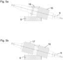
- the Figures 5a and 5b show an example of a possible structure of a grinding tool 9 as it can be used according to the invention.
- the Fig. 5a a combination tool for generating and profile grinding. Depending on the quality requirements, number of teeth, tooth width and other possible factors, this tool arrangement enables the user to use the optimal tool properties of a grinding worm 16 or a grinding wheel 18 for the process design. Of course, several grinding worms 16, 17 and/or grinding wheels 18 can also be combined with one another.
- a pure generating grinding tool for machining at least two gears with different gear geometries is shown. A tool on which only several grinding wheels or grinding wheel sets are mounted is not shown. What they all have in common is that different grinding tools for machining different gear geometries are mounted on a tool holder or a tool mandrel.
Landscapes
- Engineering & Computer Science (AREA)
- Mechanical Engineering (AREA)
- Grinding-Machine Dressing And Accessory Apparatuses (AREA)
Claims (10)
- Dispositif destiné au dressage d'outils de rectification par génération ou de rectification de profil, comprenant une unité de dressage dotée d'au moins deux logements d'outil pour recevoir au moins deux outils de dressage (8, 8*) en forme de disque, les logements d'outil étant disposés de telle sorte que les outils de dressage peuvent être mis en prise individuellement avec l'outil de rectification sans exercer d'influence mutuelle,les au moins deux logements d'outil pouvant être entraînés indépendamment l'un de l'autre et au moins un des deux logements d'outil comportant un axe de pivotement (C5, C5*) entraîné, avec lequel l'outil peut être pivoté sur un axe qui forme un angle de 10° à 90° par rapport à l'axe d'outil (B3, B3*), de telle sorte que des modifications de l'angle de pression de l'outil de rectification réalisé sous la forme d'une meule-mère peuvent ainsi être mises en oeuvre,caractérisé en ce queles deux logements d'outil pour les outils de dressage sont disposés l'un au-dessus de l'autre, de préférence avec des axes de rotation (B3, B3*) parallèles.
- Dispositif selon la revendication 1, caractérisé en ce que des outils de dressage et/ou de profilage (8, 8*) avec une géométrie de denture différente sont reçus sur les au moins deux logements d'outil entraînés.
- Dispositif selon l'une des revendications précédentes, caractérisé en ce que des outils de dressage et/ou de profilage (8, 8*) avec des diamètres différents sont reçus sur les au moins deux logements d'outil entraînés.
- Procédé de dressage d'un outil de rectification au moyen d'un dispositif selon l'une des revendications précédentes, caractérisé en ce qu'au moins deux outils de dressage (8, 8*) différents sont utilisés pour le dressage et/ou le profilage de l'outil de rectification.
- Procédé selon la revendication 4, caractérisé en ce que l'outil de rectification est usiné avec les au moins deux outils de dressage (8, 8*) différents, pour donner une géométrie de dressage définie à des zones d'outil et/ou des zones de profil de l'outil de rectification.
- Procédé selon la revendication 4 ou 5, caractérisé en ce que l'outil de rectification est usiné avec les au moins deux outils de dressage (8, 8*) différents de manière à donner une géométrie de denture différente à au moins deux zones de l'outil de rectification pour l'usinage de dentures.
- Procédé selon l'une des revendications 4 à 6, caractérisé en ce que l'outil de rectification comprend au moins deux meules-mères, deux meules ou deux jeux de meules sur un porte-outil commun.
- Procédé selon l'une des revendications précédentes 4 à 6, caractérisé en ce que l'outil de rectification comprend au moins une meule ou au moins un jeu de meules et au moins une meule-mère.
- Machine à tailler les engrenages comprenant un dispositif selon l'une des revendications 1 à 3 et en particulier destinée à exécuter le procédé selon l'une des revendications 4 à 8.
- Programme de commande pour l'exécution automatisée du procédé selon l'une des revendications 4 à 8 sur une machine à tailler les engrenages selon la revendication 9.
Applications Claiming Priority (1)
| Application Number | Priority Date | Filing Date | Title |
|---|---|---|---|
| DE102013011048.3A DE102013011048A1 (de) | 2013-07-02 | 2013-07-02 | Doppelabrichter |
Publications (4)
| Publication Number | Publication Date |
|---|---|
| EP2823924A2 EP2823924A2 (fr) | 2015-01-14 |
| EP2823924A3 EP2823924A3 (fr) | 2015-10-21 |
| EP2823924B1 EP2823924B1 (fr) | 2020-08-05 |
| EP2823924B2 true EP2823924B2 (fr) | 2025-01-01 |
Family
ID=50897459
Family Applications (1)
| Application Number | Title | Priority Date | Filing Date |
|---|---|---|---|
| EP14171795.9A Active EP2823924B2 (fr) | 2013-07-02 | 2014-06-10 | Machine à dresser double |
Country Status (5)
| Country | Link |
|---|---|
| US (1) | US9399279B2 (fr) |
| EP (1) | EP2823924B2 (fr) |
| KR (1) | KR102231123B1 (fr) |
| CN (1) | CN104275532B (fr) |
| DE (1) | DE102013011048A1 (fr) |
Families Citing this family (26)
| Publication number | Priority date | Publication date | Assignee | Title |
|---|---|---|---|---|
| US10639734B2 (en) * | 2014-12-17 | 2020-05-05 | Pratt & Whitney Canada Corp | System and method for automated machining of toothed members |
| US10315254B2 (en) * | 2015-02-23 | 2019-06-11 | Ford Motor Company | Method of machining dissimilar materials |
| DE102015104242A1 (de) * | 2015-03-20 | 2016-09-22 | Profilator Gmbh & Co. Kg | Verzahnungsverfahren mit Zahnnachbearbeitung |
| DE102015008963A1 (de) | 2015-07-10 | 2017-01-12 | Liebherr-Verzahntechnik Gmbh | Verfahren zum Abrichten eines Werkzeuges |
| DE102015008964A1 (de) | 2015-07-10 | 2017-01-12 | Liebherr-Verzahntechnik Gmbh | Verfahren zum Abrichten eines Werkzeuges |
| DE102015009017A1 (de) | 2015-07-10 | 2017-01-12 | Liebherr-Verzahntechnik Gmbh | Verfahren zur Herstellung eines verzahnten Werkstückes mit modifizierter Oberflächengeometrie |
| DE102015009287A1 (de) * | 2015-07-10 | 2017-01-12 | Liebherr-Verzahntechnik Gmbh | Verfahren zur Herstellung eines Werkstückes mit gewünschter Verzahnungsgeometrie |
| DE102015008962A1 (de) * | 2015-07-10 | 2017-01-12 | Liebherr-Verzahntechnik Gmbh | Verfahren zum Abrichten einer mehrgängigen Schleifschnecke |
| DE102015008972A1 (de) | 2015-07-10 | 2017-01-12 | Liebherr-Verzahntechnik Gmbh | Verfahren zur Herstellung eines oder mehrerer Werkstücke |
| DE102015008973A1 (de) | 2015-07-10 | 2017-01-12 | Liebherr-Verzahntechnik Gmbh | Verfahren zur Herstellung eines verzahnten Werkstückes mit modifizierter Oberflächengeometrie |
| DE102016004112A1 (de) * | 2016-04-05 | 2017-10-05 | Gleason-Pfauter Maschinenfabrik Gmbh | Verfahren zur erzeugung einer abtragung an einer zahnstirnkante und dazu ausgelegte vorrichtung |
| DE102017003648A1 (de) * | 2017-04-13 | 2018-10-18 | Liebherr-Verzahntechnik Gmbh | Verfahren zur Verzahnbearbeitung eines Werkstücks |
| DE102017006651A1 (de) | 2017-07-13 | 2019-01-17 | Gleason-Pfauter Maschinenfabrik Gmbh | Verfahren zum Erzeugen eines verzahnten Werkstücks |
| JP6656275B2 (ja) * | 2018-01-31 | 2020-03-04 | 三菱重工工作機械株式会社 | 歯車研削装置 |
| JP6653339B2 (ja) * | 2018-01-31 | 2020-02-26 | 三菱重工工作機械株式会社 | 歯車研削装置 |
| DE102019200830A1 (de) * | 2019-01-24 | 2020-07-30 | Audi Ag | Verzahnungsschleifmaschine |
| DE102019115294B4 (de) * | 2019-06-06 | 2021-04-29 | KAPP NILES GmbH & Co. KG | Verfahren zur Herstellung eines mit einer Verzahnung oder Profilierung versehenen Werkstücks |
| DE102019005405A1 (de) * | 2019-07-31 | 2021-02-04 | Gleason Switzerland Ag | Verfahren zum Hartfeinbearbeiten zweier Verzahnungen an einem Werkstück |
| CH716096B1 (de) * | 2019-09-24 | 2020-11-13 | Reishauer AG | Abrichtwerkzeug sowie ein Verfahren zum Auftragen von Hartstoffpartikeln. |
| DE102019006809A1 (de) * | 2019-09-30 | 2021-04-01 | Gleason-Pfauter Maschinenfabrik Gmbh | Verfahren der schneidenden Erzeugung oder Bearbeitung einer jeweils gleichen Verzahnung an mehreren Werkstücken |
| JP6884242B2 (ja) * | 2020-02-03 | 2021-06-09 | 三菱重工工作機械株式会社 | 歯車研削装置 |
| CN114559328B (zh) * | 2021-12-20 | 2023-04-11 | 浙江杭机股份有限公司 | 一种多工作台磨削中心 |
| KR20240000877U (ko) | 2022-11-15 | 2024-05-22 | (주)나래에프에이씨 | 테이블 드레서 |
| CN116372281A (zh) * | 2023-03-23 | 2023-07-04 | 湖南中大创远数控装备有限公司 | 一种单工位数控蜗杆砂轮磨齿机 |
| CN116393768B (zh) * | 2023-04-26 | 2025-08-26 | 重庆市倚斯轮科技有限公司 | 一种rv减速器摆线轮专用成形砂轮磨齿机及其加工方法 |
| DE102024116941A1 (de) * | 2024-06-17 | 2025-12-18 | Carl Mahr Holding Gmbh | Wälz- und/oder Profilbearbeitungswerkzeug und Verfahren zur Wälz- und/oder Profilbearbeitung eines Werkstücks |
Citations (1)
| Publication number | Priority date | Publication date | Assignee | Title |
|---|---|---|---|---|
| EP2093007A2 (fr) † | 2008-02-21 | 2009-08-26 | LIEBHERR-VERZAHNTECHNIK GmbH | Procédé destiné au fonctionnement d'une machine de ponçage de dentures |
Family Cites Families (20)
| Publication number | Priority date | Publication date | Assignee | Title |
|---|---|---|---|---|
| CH197368A (de) * | 1936-05-23 | 1938-04-30 | Herbert Lindner | Verfahren und Vorrichtung zum Profilieren und Abrichten von Formschleifscheiben, insbesondere Gewindeschleifscheiben. |
| US3339537A (en) * | 1963-10-03 | 1967-09-05 | Herbert Lindner G M B H & Co | Profile grinding wheel dressing device |
| CH458885A (de) * | 1966-02-23 | 1968-06-30 | Tos Celakovice Narodni Podnik | Schleifwerkzeug |
| US3568654A (en) * | 1968-05-15 | 1971-03-09 | Coventry Gauge & Tool Co Ltd | Grinding wheel dressing apparatus |
| US3747584A (en) * | 1972-01-24 | 1973-07-24 | Toyoda Machine Works Ltd | Rotary dressing apparatus |
| DE3433044A1 (de) * | 1983-09-24 | 1985-04-04 | Hauni-Werke Körber & Co KG, 2050 Hamburg | Abrichteinrichtung fuer bahngesteuertes abrichten von schleifscheibenprofilen |
| DD225364A1 (de) * | 1983-12-27 | 1985-07-31 | Wtz Getriebe & Kupplungen Veb | Verfahren zum mehrgaengigen schraubwaelzschleifen |
| EP0328482B1 (fr) | 1988-02-12 | 1993-07-14 | Reishauer Ag. | Outil rotatif en forme de disque pour le profilage de vis de meulage cylindriques pour la rectification de roues dentées |
| DD297357A5 (de) * | 1990-08-30 | 1992-01-09 | Niles Werkzeugmaschinen Gmbh Berlin,De | Verfahren und einrichtung zum abrichten von zylindrischen ein- und mehrgaengigen schleifschnecken |
| JPH07506301A (ja) | 1993-02-18 | 1995-07-13 | キャタピラー インコーポレイテッド | 研削及び仕上げウォーム |
| DE19624842C2 (de) | 1996-06-21 | 2000-08-10 | Reishauer Ag | Verfahren zum flexiblen Profilieren von Schleifschnecken, ein Profilierwerkzeug und eine Vorrichtung zur Durchführung des Verfahrens |
| US6491568B1 (en) | 1997-02-21 | 2002-12-10 | Reishauer Ag | Profiling methods and apparatus for generation of modified grinding worms |
| DE102004020364B4 (de) | 2004-04-23 | 2008-07-03 | Sew-Eurodrive Gmbh & Co. Kg | Werkzeug für die Schleifbearbeitung |
| JP4781358B2 (ja) * | 2005-06-27 | 2011-09-28 | 株式会社アライドマテリアル | 歯車用ダイヤモンドロータリードレッサならびにそれを用いた歯車加工用砥石のツルーイングおよびドレッシング方法 |
| DE102007022603A1 (de) * | 2007-05-12 | 2008-11-13 | Kapp Gmbh | Hartfeinbearbeitungsmaschine |
| DE102008010302A1 (de) | 2008-02-21 | 2009-08-27 | Liebherr-Verzahntechnik Gmbh | Vorrichtung und Verfahren zur Prototypen- und Kleinserienfertigung von Zahnrädern |
| CN201558998U (zh) * | 2009-10-19 | 2010-08-25 | 西安贝吉姆机床股份有限公司 | 蜗杆砂轮磨齿机砂轮修整机构 |
| DE102011103216A1 (de) * | 2011-06-01 | 2012-12-06 | Liebherr-Verzahntechnik Gmbh | Verfahren zum Abrichten eines Werkzeugs |
| US20130061704A1 (en) * | 2011-09-09 | 2013-03-14 | Illinois Tool Works Inc. | Enveloping spiroid gear assemblies and method of manufacturing the same |
| DE102011120449A1 (de) * | 2011-12-07 | 2013-06-13 | Gleason-Pfauter Maschinenfabrik Gmbh | Verfahren zum Schleifen von verzahnten Werkstücken und dazu ausgelegte Vorrichtung |
-
2013
- 2013-07-02 DE DE102013011048.3A patent/DE102013011048A1/de active Pending
-
2014
- 2014-06-10 EP EP14171795.9A patent/EP2823924B2/fr active Active
- 2014-07-01 US US14/321,650 patent/US9399279B2/en active Active
- 2014-07-02 KR KR1020140082426A patent/KR102231123B1/ko active Active
- 2014-07-02 CN CN201410313196.XA patent/CN104275532B/zh not_active Expired - Fee Related
Patent Citations (1)
| Publication number | Priority date | Publication date | Assignee | Title |
|---|---|---|---|---|
| EP2093007A2 (fr) † | 2008-02-21 | 2009-08-26 | LIEBHERR-VERZAHNTECHNIK GmbH | Procédé destiné au fonctionnement d'une machine de ponçage de dentures |
Also Published As
| Publication number | Publication date |
|---|---|
| CN104275532A (zh) | 2015-01-14 |
| KR102231123B1 (ko) | 2021-03-24 |
| DE102013011048A1 (de) | 2015-01-08 |
| EP2823924B1 (fr) | 2020-08-05 |
| US9399279B2 (en) | 2016-07-26 |
| EP2823924A2 (fr) | 2015-01-14 |
| EP2823924A3 (fr) | 2015-10-21 |
| KR20150004296A (ko) | 2015-01-12 |
| CN104275532B (zh) | 2019-06-14 |
| US20150011142A1 (en) | 2015-01-08 |
Similar Documents
| Publication | Publication Date | Title |
|---|---|---|
| EP2823924B1 (fr) | Machine à dresser double | |
| DE102006061759B4 (de) | Verzahnungsschleifmaschine und Verfahren zum Schleifen eines Werkstücks | |
| EP3552743B1 (fr) | Dispositif et procédé de chanfreinage d'une pièce dentée | |
| EP1987919B1 (fr) | Procédé et meuleuse destinés à profiler un outil de rectification | |
| EP3274120B1 (fr) | Procédé et dispositif d'usinage de précision de pignons trempés et dentés | |
| EP1719585B1 (fr) | Machine destinée au traitement de pièces optiques, nominalement de verres de lunettes en plastique | |
| EP2149425B1 (fr) | Procédé et dispositif de fabrication d'un rotor de compresseur à vis | |
| EP2759364B1 (fr) | Outil de ponçage de pièces dentées dotées d'un contour de collision | |
| DE10144644B4 (de) | Verfahren und Vorrichtung zum Schleifen von zentrischen Lagerstellen von Kurbelwellen | |
| EP3388179A1 (fr) | Procédé d'usinage de denture d'une pièce à usiner | |
| DE102009023275A1 (de) | Verzahnmaschine | |
| EP2529871A2 (fr) | Procédé d'ajustement d'un outil | |
| EP3151993A1 (fr) | Procédé d'usinage d'une pièce, agencement d'outil et machine à tailler les engrenages | |
| EP3412393B1 (fr) | Dispositifs et procédé de chanfreinage d'une pièce à denture intérieure | |
| DE10234707A1 (de) | Verfahren und Vorrichtung zum Schleifen eines rotationssymmetrischen Maschinenbauteils | |
| DE102012002126A1 (de) | Verfahren zur Ansteuerung der Bewegung eines Abrichtwerkzeugs | |
| DE102016004112A1 (de) | Verfahren zur erzeugung einer abtragung an einer zahnstirnkante und dazu ausgelegte vorrichtung | |
| DE102010024366A1 (de) | Verfahren zum Profilieren eines Honwerkzeugs für die Honbearbeitung einer Verzahnung eines Werkstücks | |
| WO2013083231A2 (fr) | Procédé de rectification de pièces dentées et dispositif correspondant | |
| DE805344C (de) | Nach dem Abwaelzverfahren arbeitende Verzahnungsmaschine | |
| DE10113301B4 (de) | Verfahren und Vorrichtung zum Hinterschleifen der Schneidzähne von zylindrisch oder kegelig geformten Abwalzfräsern sowie Abwalzfräser | |
| DE102015013497A1 (de) | Verfahren zum bearbeiten einer verzahnung und anordnung dafür | |
| DE102014009868A1 (de) | Verfahren und Vorrichtung zum Abrichten und Profilieren von Schleifwerkzeugen zum Verzahnungsschleifen | |
| WO2012025072A2 (fr) | Procédé de production de surfaces rodées à la pierre | |
| DE102018001106A1 (de) | Verfahren und Vorrichtung zum Bearbeiten eines Zahnrads |
Legal Events
| Date | Code | Title | Description |
|---|---|---|---|
| 17P | Request for examination filed |
Effective date: 20140610 |
|
| AK | Designated contracting states |
Kind code of ref document: A2 Designated state(s): AL AT BE BG CH CY CZ DE DK EE ES FI FR GB GR HR HU IE IS IT LI LT LU LV MC MK MT NL NO PL PT RO RS SE SI SK SM TR |
|
| AX | Request for extension of the european patent |
Extension state: BA ME |
|
| PUAI | Public reference made under article 153(3) epc to a published international application that has entered the european phase |
Free format text: ORIGINAL CODE: 0009012 |
|
| PUAL | Search report despatched |
Free format text: ORIGINAL CODE: 0009013 |
|
| AK | Designated contracting states |
Kind code of ref document: A3 Designated state(s): AL AT BE BG CH CY CZ DE DK EE ES FI FR GB GR HR HU IE IS IT LI LT LU LV MC MK MT NL NO PL PT RO RS SE SI SK SM TR |
|
| AX | Request for extension of the european patent |
Extension state: BA ME |
|
| RIC1 | Information provided on ipc code assigned before grant |
Ipc: B23F 23/12 20060101AFI20150916BHEP Ipc: B24B 53/075 20060101ALI20150916BHEP Ipc: B23F 21/02 20060101ALI20150916BHEP Ipc: B23F 21/00 20060101ALI20150916BHEP |
|
| R17P | Request for examination filed (corrected) |
Effective date: 20160420 |
|
| STAA | Information on the status of an ep patent application or granted ep patent |
Free format text: STATUS: REQUEST FOR EXAMINATION WAS MADE |
|
| R17P | Request for examination filed (corrected) |
Effective date: 20160420 |
|
| TPAC | Observations filed by third parties |
Free format text: ORIGINAL CODE: EPIDOSNTIPA |
|
| STAA | Information on the status of an ep patent application or granted ep patent |
Free format text: STATUS: EXAMINATION IS IN PROGRESS |
|
| 17Q | First examination report despatched |
Effective date: 20180828 |
|
| GRAP | Despatch of communication of intention to grant a patent |
Free format text: ORIGINAL CODE: EPIDOSNIGR1 |
|
| STAA | Information on the status of an ep patent application or granted ep patent |
Free format text: STATUS: GRANT OF PATENT IS INTENDED |
|
| INTG | Intention to grant announced |
Effective date: 20200403 |
|
| GRAS | Grant fee paid |
Free format text: ORIGINAL CODE: EPIDOSNIGR3 |
|
| GRAA | (expected) grant |
Free format text: ORIGINAL CODE: 0009210 |
|
| STAA | Information on the status of an ep patent application or granted ep patent |
Free format text: STATUS: THE PATENT HAS BEEN GRANTED |
|
| AK | Designated contracting states |
Kind code of ref document: B1 Designated state(s): AL AT BE BG CH CY CZ DE DK EE ES FI FR GB GR HR HU IE IS IT LI LT LU LV MC MK MT NL NO PL PT RO RS SE SI SK SM TR |
|
| REG | Reference to a national code |
Ref country code: GB Ref legal event code: FG4D Free format text: NOT ENGLISH |
|
| REG | Reference to a national code |
Ref country code: CH Ref legal event code: EP Ref country code: CH Ref legal event code: NV Representative=s name: KELLER AND PARTNER PATENTANWAELTE AG, CH |
|
| REG | Reference to a national code |
Ref country code: AT Ref legal event code: REF Ref document number: 1298018 Country of ref document: AT Kind code of ref document: T Effective date: 20200815 |
|
| REG | Reference to a national code |
Ref country code: DE Ref legal event code: R096 Ref document number: 502014014551 Country of ref document: DE |
|
| REG | Reference to a national code |
Ref country code: IE Ref legal event code: FG4D Free format text: LANGUAGE OF EP DOCUMENT: GERMAN |
|
| REG | Reference to a national code |
Ref country code: CH Ref legal event code: PFA Owner name: LIEBHERR-VERZAHNTECHNIK GMBH, DE Free format text: FORMER OWNER: LIEBHERR-VERZAHNTECHNIK GMBH, DE |
|
| REG | Reference to a national code |
Ref country code: LT Ref legal event code: MG4D |
|
| REG | Reference to a national code |
Ref country code: NL Ref legal event code: MP Effective date: 20200805 |
|
| PG25 | Lapsed in a contracting state [announced via postgrant information from national office to epo] |
Ref country code: ES Free format text: LAPSE BECAUSE OF FAILURE TO SUBMIT A TRANSLATION OF THE DESCRIPTION OR TO PAY THE FEE WITHIN THE PRESCRIBED TIME-LIMIT Effective date: 20200805 Ref country code: GR Free format text: LAPSE BECAUSE OF FAILURE TO SUBMIT A TRANSLATION OF THE DESCRIPTION OR TO PAY THE FEE WITHIN THE PRESCRIBED TIME-LIMIT Effective date: 20201106 Ref country code: NO Free format text: LAPSE BECAUSE OF FAILURE TO SUBMIT A TRANSLATION OF THE DESCRIPTION OR TO PAY THE FEE WITHIN THE PRESCRIBED TIME-LIMIT Effective date: 20201105 Ref country code: PT Free format text: LAPSE BECAUSE OF FAILURE TO SUBMIT A TRANSLATION OF THE DESCRIPTION OR TO PAY THE FEE WITHIN THE PRESCRIBED TIME-LIMIT Effective date: 20201207 Ref country code: SE Free format text: LAPSE BECAUSE OF FAILURE TO SUBMIT A TRANSLATION OF THE DESCRIPTION OR TO PAY THE FEE WITHIN THE PRESCRIBED TIME-LIMIT Effective date: 20200805 Ref country code: FI Free format text: LAPSE BECAUSE OF FAILURE TO SUBMIT A TRANSLATION OF THE DESCRIPTION OR TO PAY THE FEE WITHIN THE PRESCRIBED TIME-LIMIT Effective date: 20200805 Ref country code: HR Free format text: LAPSE BECAUSE OF FAILURE TO SUBMIT A TRANSLATION OF THE DESCRIPTION OR TO PAY THE FEE WITHIN THE PRESCRIBED TIME-LIMIT Effective date: 20200805 Ref country code: LT Free format text: LAPSE BECAUSE OF FAILURE TO SUBMIT A TRANSLATION OF THE DESCRIPTION OR TO PAY THE FEE WITHIN THE PRESCRIBED TIME-LIMIT Effective date: 20200805 Ref country code: BG Free format text: LAPSE BECAUSE OF FAILURE TO SUBMIT A TRANSLATION OF THE DESCRIPTION OR TO PAY THE FEE WITHIN THE PRESCRIBED TIME-LIMIT Effective date: 20201105 |
|
| PG25 | Lapsed in a contracting state [announced via postgrant information from national office to epo] |
Ref country code: NL Free format text: LAPSE BECAUSE OF FAILURE TO SUBMIT A TRANSLATION OF THE DESCRIPTION OR TO PAY THE FEE WITHIN THE PRESCRIBED TIME-LIMIT Effective date: 20200805 Ref country code: PL Free format text: LAPSE BECAUSE OF FAILURE TO SUBMIT A TRANSLATION OF THE DESCRIPTION OR TO PAY THE FEE WITHIN THE PRESCRIBED TIME-LIMIT Effective date: 20200805 Ref country code: LV Free format text: LAPSE BECAUSE OF FAILURE TO SUBMIT A TRANSLATION OF THE DESCRIPTION OR TO PAY THE FEE WITHIN THE PRESCRIBED TIME-LIMIT Effective date: 20200805 Ref country code: RS Free format text: LAPSE BECAUSE OF FAILURE TO SUBMIT A TRANSLATION OF THE DESCRIPTION OR TO PAY THE FEE WITHIN THE PRESCRIBED TIME-LIMIT Effective date: 20200805 Ref country code: IS Free format text: LAPSE BECAUSE OF FAILURE TO SUBMIT A TRANSLATION OF THE DESCRIPTION OR TO PAY THE FEE WITHIN THE PRESCRIBED TIME-LIMIT Effective date: 20201205 |
|
| PG25 | Lapsed in a contracting state [announced via postgrant information from national office to epo] |
Ref country code: EE Free format text: LAPSE BECAUSE OF FAILURE TO SUBMIT A TRANSLATION OF THE DESCRIPTION OR TO PAY THE FEE WITHIN THE PRESCRIBED TIME-LIMIT Effective date: 20200805 Ref country code: CZ Free format text: LAPSE BECAUSE OF FAILURE TO SUBMIT A TRANSLATION OF THE DESCRIPTION OR TO PAY THE FEE WITHIN THE PRESCRIBED TIME-LIMIT Effective date: 20200805 Ref country code: DK Free format text: LAPSE BECAUSE OF FAILURE TO SUBMIT A TRANSLATION OF THE DESCRIPTION OR TO PAY THE FEE WITHIN THE PRESCRIBED TIME-LIMIT Effective date: 20200805 Ref country code: SM Free format text: LAPSE BECAUSE OF FAILURE TO SUBMIT A TRANSLATION OF THE DESCRIPTION OR TO PAY THE FEE WITHIN THE PRESCRIBED TIME-LIMIT Effective date: 20200805 Ref country code: RO Free format text: LAPSE BECAUSE OF FAILURE TO SUBMIT A TRANSLATION OF THE DESCRIPTION OR TO PAY THE FEE WITHIN THE PRESCRIBED TIME-LIMIT Effective date: 20200805 |
|
| REG | Reference to a national code |
Ref country code: DE Ref legal event code: R026 Ref document number: 502014014551 Country of ref document: DE |
|
| PLBI | Opposition filed |
Free format text: ORIGINAL CODE: 0009260 |
|
| PLAX | Notice of opposition and request to file observation + time limit sent |
Free format text: ORIGINAL CODE: EPIDOSNOBS2 |
|
| PG25 | Lapsed in a contracting state [announced via postgrant information from national office to epo] |
Ref country code: AL Free format text: LAPSE BECAUSE OF FAILURE TO SUBMIT A TRANSLATION OF THE DESCRIPTION OR TO PAY THE FEE WITHIN THE PRESCRIBED TIME-LIMIT Effective date: 20200805 |
|
| 26 | Opposition filed |
Opponent name: REISHAUER AG Effective date: 20210505 |
|
| PG25 | Lapsed in a contracting state [announced via postgrant information from national office to epo] |
Ref country code: SK Free format text: LAPSE BECAUSE OF FAILURE TO SUBMIT A TRANSLATION OF THE DESCRIPTION OR TO PAY THE FEE WITHIN THE PRESCRIBED TIME-LIMIT Effective date: 20200805 |
|
| PG25 | Lapsed in a contracting state [announced via postgrant information from national office to epo] |
Ref country code: SI Free format text: LAPSE BECAUSE OF FAILURE TO SUBMIT A TRANSLATION OF THE DESCRIPTION OR TO PAY THE FEE WITHIN THE PRESCRIBED TIME-LIMIT Effective date: 20200805 |
|
| PLBB | Reply of patent proprietor to notice(s) of opposition received |
Free format text: ORIGINAL CODE: EPIDOSNOBS3 |
|
| PG25 | Lapsed in a contracting state [announced via postgrant information from national office to epo] |
Ref country code: MC Free format text: LAPSE BECAUSE OF FAILURE TO SUBMIT A TRANSLATION OF THE DESCRIPTION OR TO PAY THE FEE WITHIN THE PRESCRIBED TIME-LIMIT Effective date: 20200805 |
|
| GBPC | Gb: european patent ceased through non-payment of renewal fee |
Effective date: 20210610 |
|
| REG | Reference to a national code |
Ref country code: BE Ref legal event code: MM Effective date: 20210630 |
|
| PG25 | Lapsed in a contracting state [announced via postgrant information from national office to epo] |
Ref country code: LU Free format text: LAPSE BECAUSE OF NON-PAYMENT OF DUE FEES Effective date: 20210610 |
|
| PG25 | Lapsed in a contracting state [announced via postgrant information from national office to epo] |
Ref country code: IE Free format text: LAPSE BECAUSE OF NON-PAYMENT OF DUE FEES Effective date: 20210610 Ref country code: GB Free format text: LAPSE BECAUSE OF NON-PAYMENT OF DUE FEES Effective date: 20210610 |
|
| PG25 | Lapsed in a contracting state [announced via postgrant information from national office to epo] |
Ref country code: FR Free format text: LAPSE BECAUSE OF NON-PAYMENT OF DUE FEES Effective date: 20210630 |
|
| PG25 | Lapsed in a contracting state [announced via postgrant information from national office to epo] |
Ref country code: BE Free format text: LAPSE BECAUSE OF NON-PAYMENT OF DUE FEES Effective date: 20210630 |
|
| REG | Reference to a national code |
Ref country code: AT Ref legal event code: MM01 Ref document number: 1298018 Country of ref document: AT Kind code of ref document: T Effective date: 20210610 |
|
| PG25 | Lapsed in a contracting state [announced via postgrant information from national office to epo] |
Ref country code: AT Free format text: LAPSE BECAUSE OF NON-PAYMENT OF DUE FEES Effective date: 20210610 |
|
| PG25 | Lapsed in a contracting state [announced via postgrant information from national office to epo] |
Ref country code: HU Free format text: LAPSE BECAUSE OF FAILURE TO SUBMIT A TRANSLATION OF THE DESCRIPTION OR TO PAY THE FEE WITHIN THE PRESCRIBED TIME-LIMIT; INVALID AB INITIO Effective date: 20140610 |
|
| PG25 | Lapsed in a contracting state [announced via postgrant information from national office to epo] |
Ref country code: CY Free format text: LAPSE BECAUSE OF FAILURE TO SUBMIT A TRANSLATION OF THE DESCRIPTION OR TO PAY THE FEE WITHIN THE PRESCRIBED TIME-LIMIT Effective date: 20200805 |
|
| PG25 | Lapsed in a contracting state [announced via postgrant information from national office to epo] |
Ref country code: MK Free format text: LAPSE BECAUSE OF FAILURE TO SUBMIT A TRANSLATION OF THE DESCRIPTION OR TO PAY THE FEE WITHIN THE PRESCRIBED TIME-LIMIT Effective date: 20200805 |
|
| PG25 | Lapsed in a contracting state [announced via postgrant information from national office to epo] |
Ref country code: TR Free format text: LAPSE BECAUSE OF FAILURE TO SUBMIT A TRANSLATION OF THE DESCRIPTION OR TO PAY THE FEE WITHIN THE PRESCRIBED TIME-LIMIT Effective date: 20200805 |
|
| APBP | Date of receipt of notice of appeal recorded |
Free format text: ORIGINAL CODE: EPIDOSNNOA2O |
|
| APAH | Appeal reference modified |
Free format text: ORIGINAL CODE: EPIDOSCREFNO |
|
| APAW | Appeal reference deleted |
Free format text: ORIGINAL CODE: EPIDOSDREFNO |
|
| APBU | Appeal procedure closed |
Free format text: ORIGINAL CODE: EPIDOSNNOA9O |
|
| PG25 | Lapsed in a contracting state [announced via postgrant information from national office to epo] |
Ref country code: MT Free format text: LAPSE BECAUSE OF FAILURE TO SUBMIT A TRANSLATION OF THE DESCRIPTION OR TO PAY THE FEE WITHIN THE PRESCRIBED TIME-LIMIT Effective date: 20200805 |
|
| PUAH | Patent maintained in amended form |
Free format text: ORIGINAL CODE: 0009272 |
|
| STAA | Information on the status of an ep patent application or granted ep patent |
Free format text: STATUS: PATENT MAINTAINED AS AMENDED |
|
| 27A | Patent maintained in amended form |
Effective date: 20250101 |
|
| AK | Designated contracting states |
Kind code of ref document: B2 Designated state(s): AL AT BE BG CH CY CZ DE DK EE ES FI FR GB GR HR HU IE IS IT LI LT LU LV MC MK MT NL NO PL PT RO RS SE SI SK SM TR |
|
| REG | Reference to a national code |
Ref country code: DE Ref legal event code: R102 Ref document number: 502014014551 Country of ref document: DE |
|
| PGFP | Annual fee paid to national office [announced via postgrant information from national office to epo] |
Ref country code: DE Payment date: 20250630 Year of fee payment: 12 |
|
| PGFP | Annual fee paid to national office [announced via postgrant information from national office to epo] |
Ref country code: IT Payment date: 20250627 Year of fee payment: 12 |
|
| PGFP | Annual fee paid to national office [announced via postgrant information from national office to epo] |
Ref country code: CH Payment date: 20250701 Year of fee payment: 12 |