EP2824019A1 - Unité d'entraînement pour un entraînement d'aide à la conduite - Google Patents
Unité d'entraînement pour un entraînement d'aide à la conduite Download PDFInfo
- Publication number
- EP2824019A1 EP2824019A1 EP14176083.5A EP14176083A EP2824019A1 EP 2824019 A1 EP2824019 A1 EP 2824019A1 EP 14176083 A EP14176083 A EP 14176083A EP 2824019 A1 EP2824019 A1 EP 2824019A1
- Authority
- EP
- European Patent Office
- Prior art keywords
- drive
- drive unit
- unit according
- gear
- rotation
- Prior art date
- Legal status (The legal status is an assumption and is not a legal conclusion. Google has not performed a legal analysis and makes no representation as to the accuracy of the status listed.)
- Granted
Links
- 230000008878 coupling Effects 0.000 claims abstract description 22
- 238000010168 coupling process Methods 0.000 claims abstract description 22
- 238000005859 coupling reaction Methods 0.000 claims abstract description 22
- 230000005540 biological transmission Effects 0.000 claims description 33
- 238000004891 communication Methods 0.000 claims description 4
- 230000000977 initiatory effect Effects 0.000 claims 1
- 238000005096 rolling process Methods 0.000 description 4
- 238000010276 construction Methods 0.000 description 3
- 230000000903 blocking effect Effects 0.000 description 2
- 230000008602 contraction Effects 0.000 description 2
- 239000000725 suspension Substances 0.000 description 2
- 229910000831 Steel Inorganic materials 0.000 description 1
- 239000006096 absorbing agent Substances 0.000 description 1
- 230000015572 biosynthetic process Effects 0.000 description 1
- 238000013016 damping Methods 0.000 description 1
- 238000005553 drilling Methods 0.000 description 1
- 230000000694 effects Effects 0.000 description 1
- 230000002349 favourable effect Effects 0.000 description 1
- 239000002184 metal Substances 0.000 description 1
- 230000002040 relaxant effect Effects 0.000 description 1
- 230000035939 shock Effects 0.000 description 1
- 239000010959 steel Substances 0.000 description 1
- 239000013589 supplement Substances 0.000 description 1
Images




Classifications
-
- B—PERFORMING OPERATIONS; TRANSPORTING
- B62—LAND VEHICLES FOR TRAVELLING OTHERWISE THAN ON RAILS
- B62D—MOTOR VEHICLES; TRAILERS
- B62D59/00—Trailers with driven ground wheels or the like
- B62D59/04—Trailers with driven ground wheels or the like driven from propulsion unit on trailer
Definitions
- the invention relates to a drive unit for a Hilfsfahrantrieb of foreign moving vehicles, especially trailers, with the features in the preamble of the main claim.
- Such a drive unit is from the EP 2 138 387 A1 known.
- the drive unit has a drive train with a driving drive generating the drive, a transmission and a force acting on a vehicle wheel driving wheel.
- the gearbox is designed to be self-locking in order to prevent the vehicle from rolling back in the event of a power failure of the drive unit and when driving uphill.
- the invention solves this problem with the features in the main claim.
- the claimed coupling device has the advantage that with it the driving function of the drive train can be controlled as needed.
- the coupling device can transmit a rotation introduced on the drive side and forward it to the drive wheel.
- it can lock or brake a rotation initiated in the opposite direction from the load side or driven side.
- the said transmission and blocking or braking effects are preferably in each case in both directions of rotation. In this way, in case of drive failure unwanted rolling away of the vehicle by its own weight or by other external influence can be prevented.
- the coupling device can be designed in different ways. Special advantages has a training as wrap spring clutch or load torque lock. This also works in the event of a power failure and can reliably prevent the mentioned unwanted rolling away of the vehicle and lock or brake a so-called towing mode on the driven side.
- a wrap spring clutch also has the advantage that it generates less losses in the drive train than a self-locking transmission. The efficiency of the drive unit and the drive train can be increased.
- a wrap spring clutch also has the advantage that it can do without an actuator and acts automatically.
- the coupling device in particular the wrap spring clutch, can be arranged at any point of the drive train. Particular advantages arise in an arrangement within the transmission. This is favorable in terms of space and efficiency.
- the claimed drive unit may have a gearbox that does not require any self-locking as a whole or at least in some gear stages.
- the drive side subsequent gear stage can be designed as a worm gear.
- the drive unit preferably has a single drive train with only one drive drive and one drive wheel.
- the individual drive unit acts only on a single vehicle and this can individually and independently of another, especially on the other side of the vehicle arranged driving vehicle. By a different actuation of both sides of the vehicle arranged drive units, the vehicle can be moved and thereby directed as needed.
- the clutch device in particular the wrap spring clutch, is arranged between the first gear stage adjacent to the drive drive and the second gear stage.
- the first gear stage is preferably designed as a worm gear. It may alternatively have a different transmission design.
- the transmission may have two, three or more gear stages, wherein the second and third and optionally following gear stages are preferably designed as a spur gear.
- the transmission in particular the second and third and possibly following transmission stages, can / can be designed without self-locking.
- a spur gear or other suitable gear design useful.
- the drive wheel is preferably designed as a rotatable roller with a low-cost jacket, in particular a ribbed jacket.
- the drive unit may have a support device for attachment to the vehicle, in particular to its chassis.
- the attachment may e.g. take place on each adjacent side member.
- the invention relates to a drive unit (10, 11) for an auxiliary traction drive (2) of foreign-moving vehicles (1), in particular trailers.
- the invention further relates to the auxiliary drive (2) and a vehicle equipped with an auxiliary drive (2) vehicle (1).
- the vehicle (1) can be of any type and size. Preferably, it is a foreign-moving vehicle, in particular a vehicle trailer, of a towing vehicle can be pulled.
- the trailer (1) can be a car trailer.
- FIG. 1 shows such a trailer (1) in a schematic representation. It has a chassis (3) with a front rigid drawbar (4) carrying a hitch (5).
- the drawbar (4) can be designed, for example, as a V-drawbar or as a pipe drawbar.
- the trailer (1) also has at least one axle (8) with vehicle wheels (9) mounted at the end on hubs. The one or more axles (8) are suitably fixed to the chassis or chassis (3).
- the chassis or chassis (3) has one or more side members (6), e.g. are formed as folded metal profiles, in particular steel profiles, with a cross section in C, U, L or Z shape.
- the longitudinal members (6) can be interconnected by one or more cross members (7).
- a cross connection can alternatively or additionally take place via a structure.
- the one or more axes (8) may be formed in any suitable manner, e.g. as a trailing arm or trailing arm axle.
- the axle (8) may have an integrated suspension in the form of rubber cords, torsion bars or the like.
- the axle (8) may also have end Radlenker with wheel journal for receiving the wheel hub.
- shock absorbers or other suitable damping means e.g. an air suspension, be present.
- the vehicle or the trailer (1) may have a structure of any type and size, which is connected to the chassis (3) or is connected.
- FIG. 1 For example, a caravan construction or a box construction is indicated.
- the vehicle (1) or the trailer a Power supply with connection to the socket of a towing vehicle or to an external power source, in particular power source, have.
- a trailer (1) may also have a braking device, which may be designed as a service brake and / or as a parking brake.
- the vehicle shown may, for example, according to EP 2 138 387 A1 be educated.
- the auxiliary drive (2) is used for motorized movement of the vehicle (1). This can e.g. a shunting of an uncoupled from the towing vehicle trailer (1).
- the auxiliary drive (2) may be a Rangierantrieb, with the e.g. a caravan or other bulky trailer is moved to a parking space. Otherwise, the auxiliary drive (2) can also be used in conjunction with other vehicles (1) and for other purposes.
- the auxiliary traction drive (2) has at least one drive unit (10, 11) which has a drive train with a drive drive (17), a transmission (21) and a drive wheel (15) acting on a vehicle wheel (9).
- the drive drive (17) serves to generate the propulsion and to the rotating drive of the drive wheel (15).
- the drive wheel (15) can act in any suitable manner on the vehicle wheel (9) and have an appropriate training for this purpose.
- the drive wheel (15) may e.g. be pressed against the tread of the vehicle wheel (9) and rotates the vehicle wheel (9) in the drive case with.
- the drive wheel (15) can be for this purpose e.g. be designed as a drive roller with a corrugated sheath.
- the drive wheel (15) may be a gear, which is brought into drive connection with a counter gear on the vehicle wheel (9).
- the auxiliary drive (2) has at least one, preferably a plurality of drive units (10, 11).
- a drive unit (10, 11) is arranged on both longitudinal sides. It can be arranged in the direction of travel or pulling (16) in front of or behind the vehicle wheel (9).
- drive units (10, 11) can be present.
- the respective drive unit (10, 11) has a single drive train with only one drive drive (17), one transmission (21) and one drive wheel (15) acting on the vehicle wheel (9).
- the individual drive unit (10, 11) acts in each case only on the one assigned vehicle wheel (9).
- the drive unit (10, 11) has a support device (13) with which it can be fastened to the vehicle (1).
- the attachment is preferably carried out on the chassis or on the chassis (3), in particular on the respectively adjacent side member (6).
- additional support (14) may be present. This is formed, for example, as a transverse strut for connecting the longitudinal members (6).
- the support (14) may be formed as an oblique strut with support on the axis (8).
- the drive unit (10, 11) can also have an in FIG. 2 schematically indicated feed device (12), with the drive wheel (15) individually or alternatively together with the drive unit (10,11) is delivered to the vehicle wheel (9) in a translatory or rotary or combined translational / rotational movement.
- the delivery can be made from a retracted non-contact rest position into a contacting working position on the vehicle wheel (9).
- the formation of the feed device (12), the support device (13) and the drive wheel (15) can also the EP 2 138 387 A1 correspond.
- the drive unit (10,11) has a housing which surrounds the aforementioned drive train.
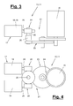
- FIGS. 3 and 4 illustrate in a schematic representation of the drive train with the series connection of drive drive (17), gear (21) and drive wheel (15).
- a clutch device (26) is arranged in the drive train. This can also be present several times.
- the coupling device (26) transmits a drive introduced by the drive drive (17) rotation and a drive torque and forwards them to the drive wheel (15).
- the coupling device (26) can lock or brake a rotation along the output side and from the vehicle wheel (9) along with load or drag torque and thereby brake or block a rotational movement of the vehicle wheel (9).
- the coupling device (26) can be designed in such a way that a rotation introduced on the drive side is possible in both directions of rotation, i. Forward and reverse rotation, transmits. Alternatively, a rotation introduced on the drive side can only be transmitted in one direction of rotation.
- the coupling device (26) can lock or brake a rotation initiated on the output side in both directions of rotation or alternatively only in one direction of rotation.
- the coupling device (26) can be designed in different ways. In the embodiments shown, it is designed as a wrap spring clutch. It can be single or multiple.
- the wrap spring clutch (26) may include one or more wrap springs (36).
- the coupling device (26) can be arranged in the drive train at any desired location, in particular between the drive drive (17) and the drive wheel (15). Preferably, it is arranged in the gearbox (21) or possibly also in the drive wheel (15).
- the transmission (21) can according to FIGS. 3 and 4 be multi-level.
- the coupling device (26) can be arranged between two gear stages.
- the transmission (21) has three successive gear stages I, II, III (22,23,24), which are preferably designed as a gear transmission.
- the first gear stage I (22), which adjoins the drive drive (17), preferably directly following it, can be used, for example, as an example. be designed as a worm gear and have a driven gear shaft (25).
- This is coupled to the following gear stage II (23), e.g. is designed as a spur gear with pinion and large gear.
- the output shaft of the large gear is coupled to the following gear stage III (24), which also has a pinion and a large gear, wherein the output shaft of the gear stage III is connected to the drive wheel (15).
- the transmission (21) as a whole or at least individual gear stages (22, 23, 24) can be designed without self-locking.
- the coupling device (26) preferably the wrap spring clutch, between the gear stages I and II (22,23) arranged.
- the coupling device (26) is coupled to the transmission shaft (25).
- the transmission shaft (25) can be connected to the clutch device (26) in a drive-side and a driven-side Be shared part shaft, wherein the shaft parts can be aligned with each other on their common axis of rotation or alternatively may have a lateral offset to each other.
- the drive drive (17) may be formed in any suitable manner. It may be one or more suitable drive means, e.g. Motors, in particular electric motors have. In the embodiment shown, two electric motors are arranged in parallel and drive together to the first gear stage I (22). For this purpose, e.g. on each motor shaft (20) of the motors (18,19) a gear (28), e.g. a worm, wherein the worms (28) mesh with the common gear (29) or large gear at opposite points.
- suitable drive means e.g. Motors, in particular electric motors have.
- two electric motors are arranged in parallel and drive together to the first gear stage I (22).
- a gear (28) e.g. a worm, wherein the worms (28) mesh with the common gear (29) or large gear at opposite points.
- FIGS. 5 to 10 show a constructive embodiment of a drive train with a drive drive (17), a multi-stage transmission (21), a drive wheel (15) and arranged in the drive train wrap spring clutch (26).
- the transmission (21) has three gear stages I, II, III (22, 23, 24), wherein the wrap spring clutch (26) is arranged between the first and second gear stage (22, 23). It is located on the output shaft (25) between the large gear (29) and the pinion (32) of the second second gear stage (23).
- the first gear stage (22) can be configured in the aforementioned manner as a worm gear with two worm shafts (28) meshing with the gearwheel (29) or large gear opposite each other.
- the gear (29) may e.g. have an inhibition-reducing helical toothing.
- the gear or large gear (29) of the first gear stage (22) has a central bore (30) and there radially inwardly projecting and extending in the axial direction driver (31), for example, as an inner bar is trained.
- the gear (29) may also have a sleeve-like axial projection on the front.
- the gear shaft (25) is formed as a sleeve (33) which is connected at the rear end with the gear or pinion (32).
- the sleeve (33) extends through the bore (30) of the large gear (29) and has an axial jacket recess (34) whose arrangement and size is matched to the inner strip (31).
- the jacket recess (34) is e.g. formed as a slot in the sleeve casing and extends to the free end of the sleeve.
- the wrap spring clutch (26) has a central support element (35), which is arranged rotationally fixed.
- the support element (35) is preferably designed as a bolt, according to FIG. 8 may have a stepped shape.
- the support element (35) can be arranged, for example, stationary on the housing of the drive unit (10, 11).
- the pinion (32) with the sleeve (33) is rotatably supported and supported.
- the large wheel (29) is guided and supported on the sleeve (33) and supported on the bolt (35).
- the large wheel (29) can not or only slightly rotate relative to the sleeve (33).
- the wrap spring (36) On the bolt (35) is also arranged with clamping seat, the wrap spring (36).
- This is helical spring-shaped and has at the ends in each case a transversely, in particular radially to the central axis projecting spring arm (37,38).
- the spring arms (37,38) are received in the Mantelaus strictlyung (34) and protrude through it. They are also arranged on both sides of the inner strip (31), which also engages in the Mantelaus brieflyung (34).
- the spring arms (37, 38) interact with the driver (31) on the inside in each case and with the adjacent axial edge of the jacket recess (34) on the outside.
- the contracting wrap spring (36) retracts onto the pin (35) and blocks rotation of the large gear (29), motor shaft (25) and sleeve (33) and Ritzel's (32). If in this case the vehicle (1) a drag or load torque on the drive wheel (15) and the gear (21) with the pinion (32) is initiated act in each direction of rotation, the edges of the Mantelaus originallyung (34) from the outside against the respectively adjacent Spring arm (37,38). As a result, they additionally tension the wrap spring (36), as a result of which the external load moment in the wrap spring clutch (26) is received and supported via the stationary pin (35) by clamping. As a result, the vehicle wheels (9) can not turn. The vehicle (1) can thus not roll by itself or by external influence.
- the wrap spring clutch (26) can in another variant, for example according to EP 0 118 555 B1 be designed, and preferably the drive-side rotations and Transmits torques in both directions of rotation and brakes or blocks the backward from the output side rotations and drag or load moments by contraction of the wrap spring.
- the wrap spring can likewise be mounted on a non-rotatable bolt and have at its ends outwardly projecting spring arms with a radial directional component, which are connected concentrically to the journal and superimposed sleeves via jacket recesses and stops.
- a sleeve is connected to the drive side and a sleeve to the output side.
- the drive-side sleeve causes in their rotation in both directions of rotation in each case a relaxation and entrainment of the wrap spring.
- the output-side sleeve causes in their rotation in both directions of rotation in each case a contraction of the wrap spring on the non-rotatable pin, resulting in said braking or blocking the sleeve rotational movement.
- wrap spring clutches (26) are automatic, their transmission and braking / locking function depending on whether the rotation and the torque are introduced from the drive side or from the load or driven side. In these embodiments, the wrap spring clutch (26) comes out without additional actuator or drive.
- the wrap spring clutch (26) automatically prevents the vehicle from rolling in the so-called drag mode due to its own weight or other external influences and when the drive wheel (15) engages the vehicle wheel (9). ,
- the wrap spring clutch (26) can also replace or supplement the parking brake of the vehicle (1).
- the wrap spring clutch (26) may comprise an actuator which provides for tensioning or contracting and relaxing or releasing the one or more wrap springs. This actuator can act against the force of a tension spring, which contracts the wrap spring.
- the coupling device (26) to fulfill the aforementioned transmission and braking / locking functions have any other suitable training.
- the drive (17) can be an integrated controller with a control board and a communication device for communication with another drive unit (10,11) or with an optionally existing external and for several drive units (10,11) common control (27) (see , FIG. 2 ) exhibit. Communication may be via a bus system using wireline or wireless data transmission.
- the controls integrated in the drive units (10, 11) can be motor controls for the drive drive (17) and the motorized feed device (12).
- the common control (27) can be superordinate.
- one of the integrated controls of the drive units (10,11) take over the task of the higher-level control (27).
- the training of the controls can be done according to the EP 2 138 387 A or according to the DE 20 2010 008 600 U1 be.
- auxiliary drive (2) The operation of the auxiliary drive (2) and its one or more drive units (10,11) by means of an operating device (39), for example, the in FIG. 1 shown wireless or wired remote control, done.
- security features can also be implemented which include actuating the auxiliary drive drive (2) in the coupled state on the towing vehicle or an operator from the towing vehicle prevent.
- Another safety feature is the need-based shutdown of the auxiliary drive (2) to save energy, a Softanlauf and Softstop etc.
- the auxiliary driving device (2) or the vehicle equipped therewith (1) may have a corresponding safety device, for example, according to DE 20 2009 005 185 U1 can be trained.
- the drive units (10, 11) mounted on the left and right of the vehicle (1) can be operated independently.
- the vehicle (1) can thereby be steered and maneuvered in the direction and speed. It can drive straight or in any curves and turn on the spot.
- the number of drive units (10, 11) and their arrangement on the vehicle (1) can vary.
- the feed device (12) can only move the drive wheel (15), wherein the transmission (21) is designed accordingly and the drive drive (17) is arranged fixed to the vehicle.
- Such a construction may, for example, according to DE 20 2010 005 650 U1 be educated.
- the drive motor (17) may have other motor drive means in a different number and arrangement. For example, he can only have one electric motor.
- the engine number can also be greater than two and be eg three or four. Instead of electric motors and other engine designs can be used.
- the transmission (21) can be carried out in other ways. There may be a different number of gear stages, e.g. only one or two gear stages have. The number of stages can also be four or more.
- the structural design of the one or more gear stages may vary.
- the first gear stage I (22) may e.g. be designed as a spur gear or bevel gear. A training of a gear as a crown gear is possible.
- the drive wheel (15) may be formed as a gear and as part of the transmission (21), in particular as a driven gear.
- the transmission (21) may also have a different transmission design, e.g. as planetary gear, step transmission or the like. Further, other transmission means, e.g. Handlebars are used.
- the wrap spring clutch (26) can also be modified.
- the support element (35) may be formed, for example, as a sleeve in which the wrap spring (36) is clamped.
- the shaft (25) can be released and rotated.
Landscapes
- Engineering & Computer Science (AREA)
- Chemical & Material Sciences (AREA)
- Combustion & Propulsion (AREA)
- Transportation (AREA)
- Mechanical Engineering (AREA)
- Arrangement And Driving Of Transmission Devices (AREA)
- Gear Transmission (AREA)
Applications Claiming Priority (1)
| Application Number | Priority Date | Filing Date | Title |
|---|---|---|---|
| DE202013103040.6U DE202013103040U1 (de) | 2013-07-09 | 2013-07-09 | Antriebseinheit für einen Hilfsfahrantrieb |
Publications (2)
| Publication Number | Publication Date |
|---|---|
| EP2824019A1 true EP2824019A1 (fr) | 2015-01-14 |
| EP2824019B1 EP2824019B1 (fr) | 2016-10-05 |
Family
ID=51211025
Family Applications (1)
| Application Number | Title | Priority Date | Filing Date |
|---|---|---|---|
| EP14176083.5A Not-in-force EP2824019B1 (fr) | 2013-07-09 | 2014-07-08 | Unité d'entraînement pour un entraînement d'aide à la conduite |
Country Status (2)
| Country | Link |
|---|---|
| EP (1) | EP2824019B1 (fr) |
| DE (1) | DE202013103040U1 (fr) |
Families Citing this family (2)
| Publication number | Priority date | Publication date | Assignee | Title |
|---|---|---|---|---|
| CN107776704A (zh) * | 2016-08-25 | 2018-03-09 | 杭州嘉迈机械有限公司 | 调车驱动系统及带有该调车驱动系统的车辆 |
| DE102018212648A1 (de) * | 2018-07-30 | 2020-01-30 | Siemens Aktiengesellschaft | Trennschalter und Antriebsvorrichtung für einen Trennschalter |
Citations (6)
| Publication number | Priority date | Publication date | Assignee | Title |
|---|---|---|---|---|
| EP0118555B1 (fr) | 1982-09-13 | 1988-05-18 | General Clutch Corp. | Ameliorations aux embrayages a ressorts |
| EP2138387A1 (fr) | 2008-06-25 | 2009-12-30 | AL-KO Kober AG | Entraînement auxiliaire |
| DE202009005185U1 (de) | 2009-08-26 | 2011-01-20 | Al-Ko Kober Ag | Hilfsantrieb |
| DE202010005650U1 (de) | 2010-06-16 | 2011-10-13 | Al-Ko Kober Ag | Hilfsfahrantrieb |
| DE202010008600U1 (de) | 2010-09-21 | 2011-12-27 | Al-Ko Kober Ag | Hilfsfahrantrieb |
| EP2669156A2 (fr) * | 2012-05-29 | 2013-12-04 | Truma Gerätetechnik GmbH & Co. KG | Entraînement de rangement pour remorque avec une disposition coaxiale des composants de l'entraînement |
Family Cites Families (2)
| Publication number | Priority date | Publication date | Assignee | Title |
|---|---|---|---|---|
| DE547778C (de) | 1930-06-04 | 1932-03-30 | Vogtlaendische Maschinenfabrik | Lastwagenzug |
| DE2711214A1 (de) | 1977-03-15 | 1979-01-25 | Josef Dipl Ing Koza | Hilfsantrieb fuer nicht angetriebene raeder von kraftfahrzeugen |
-
2013
- 2013-07-09 DE DE202013103040.6U patent/DE202013103040U1/de not_active Expired - Lifetime
-
2014
- 2014-07-08 EP EP14176083.5A patent/EP2824019B1/fr not_active Not-in-force
Patent Citations (6)
| Publication number | Priority date | Publication date | Assignee | Title |
|---|---|---|---|---|
| EP0118555B1 (fr) | 1982-09-13 | 1988-05-18 | General Clutch Corp. | Ameliorations aux embrayages a ressorts |
| EP2138387A1 (fr) | 2008-06-25 | 2009-12-30 | AL-KO Kober AG | Entraînement auxiliaire |
| DE202009005185U1 (de) | 2009-08-26 | 2011-01-20 | Al-Ko Kober Ag | Hilfsantrieb |
| DE202010005650U1 (de) | 2010-06-16 | 2011-10-13 | Al-Ko Kober Ag | Hilfsfahrantrieb |
| DE202010008600U1 (de) | 2010-09-21 | 2011-12-27 | Al-Ko Kober Ag | Hilfsfahrantrieb |
| EP2669156A2 (fr) * | 2012-05-29 | 2013-12-04 | Truma Gerätetechnik GmbH & Co. KG | Entraînement de rangement pour remorque avec une disposition coaxiale des composants de l'entraînement |
Also Published As
| Publication number | Publication date |
|---|---|
| DE202013103040U1 (de) | 2014-10-10 |
| EP2824019B1 (fr) | 2016-10-05 |
Similar Documents
| Publication | Publication Date | Title |
|---|---|---|
| EP3426545B1 (fr) | Unité d'entraînement et procédé d'entraînement | |
| EP2739497A1 (fr) | Dispositif d'entraînement pour une roue distincte d'un véhicule automobile | |
| DE112019004130T5 (de) | Elektrische Achsanordnung | |
| EP2593393B1 (fr) | Treuil | |
| DE102009055021A1 (de) | Mehrfach verstellbare Lenkbestätigungseinheit für ein Kraftfahrzeug mit einem Träger und einer Lenksäule | |
| DE2710585B1 (de) | Bremseinrichtung fuer Fahrzeuge,insbesondere fuer Schienenfahrzeuge,mit einem Federspeicher-Bremsgeraet | |
| EP3165433B1 (fr) | Entraînement de rangement pour remorque | |
| DE19681259C2 (de) | Antriebssystem eines Antriebsrades | |
| WO2021244913A1 (fr) | Véhicule utilitaire pourvu d'un frein de stationnement | |
| DE19727289A1 (de) | Einsatzfahrzeug, insbesondere Feuerwehrfahrzeug, für den Straßen- und Schienenbetrieb | |
| DE102011012089A1 (de) | Rangiersystem für einen mehrachsigen Anhänger | |
| EP2824019B1 (fr) | Unité d'entraînement pour un entraînement d'aide à la conduite | |
| DE102018209819A1 (de) | Spindelantrieb für eine steer-by-wire-Lenkung sowie steer-by-wire-Lenkung | |
| DE10327458A1 (de) | Bremsanlage für Kraftfahrzeuge | |
| EP3191326B1 (fr) | Unité d'essieu | |
| DE3920934A1 (de) | Anhaengereigene antriebseinrichtung | |
| DE2025555C3 (de) | Antriebsanordnung für ein elektrisches Triebfahrzeug | |
| DE102020004086B3 (de) | Schwerlast-Transportfahrzeug mit einer Antriebseinrichtung | |
| DE102006007072B3 (de) | Vorrichtung zum mechanischen Lösen einer motorisch betätigten Feststellbremse für ein Kraftfahrzeug | |
| DE102024116827B4 (de) | Anordnung einer Schienenfahrzeugbremse und eines Schienenfahrzeugs, insbesondere Güterwagen, mit automatisierter bzw. motorisierter Park- und Feststellbremse und Schienenfahrzeug, insbesondere Güterwagen, mit einer solchen Anordnung | |
| DE102015224599A1 (de) | Nutzfahrzeug, insbesondere Schwerlastfahrzeug | |
| DE102015220776A1 (de) | Radaufhängung für ein lenkbares Fahrzeugrad eines Kraftfahrzeuges | |
| EP3936384A1 (fr) | Véhicule de transport des charges lourdes doté d'un dispositif d'entraînement | |
| DE102015214721A1 (de) | Exzenterverstelleinheit zur Verstellung eines Anbindungspunkts für einen Lenker einer Radaufhängung sowie Radaufhängung mit der Exzenterverstelleinheit | |
| DE202010005650U1 (de) | Hilfsfahrantrieb |
Legal Events
| Date | Code | Title | Description |
|---|---|---|---|
| 17P | Request for examination filed |
Effective date: 20140708 |
|
| AK | Designated contracting states |
Kind code of ref document: A1 Designated state(s): AL AT BE BG CH CY CZ DE DK EE ES FI FR GB GR HR HU IE IS IT LI LT LU LV MC MK MT NL NO PL PT RO RS SE SI SK SM TR |
|
| AX | Request for extension of the european patent |
Extension state: BA ME |
|
| PUAI | Public reference made under article 153(3) epc to a published international application that has entered the european phase |
Free format text: ORIGINAL CODE: 0009012 |
|
| R17P | Request for examination filed (corrected) |
Effective date: 20150713 |
|
| RBV | Designated contracting states (corrected) |
Designated state(s): AL AT BE BG CH CY CZ DE DK EE ES FI FR GB GR HR HU IE IS IT LI LT LU LV MC MK MT NL NO PL PT RO RS SE SI SK SM TR |
|
| GRAP | Despatch of communication of intention to grant a patent |
Free format text: ORIGINAL CODE: EPIDOSNIGR1 |
|
| RIC1 | Information provided on ipc code assigned before grant |
Ipc: B62D 59/04 20060101AFI20160524BHEP |
|
| INTG | Intention to grant announced |
Effective date: 20160607 |
|
| GRAS | Grant fee paid |
Free format text: ORIGINAL CODE: EPIDOSNIGR3 |
|
| GRAA | (expected) grant |
Free format text: ORIGINAL CODE: 0009210 |
|
| AK | Designated contracting states |
Kind code of ref document: B1 Designated state(s): AL AT BE BG CH CY CZ DE DK EE ES FI FR GB GR HR HU IE IS IT LI LT LU LV MC MK MT NL NO PL PT RO RS SE SI SK SM TR |
|
| REG | Reference to a national code |
Ref country code: GB Ref legal event code: FG4D Free format text: NOT ENGLISH |
|
| REG | Reference to a national code |
Ref country code: CH Ref legal event code: EP |
|
| REG | Reference to a national code |
Ref country code: AT Ref legal event code: REF Ref document number: 834356 Country of ref document: AT Kind code of ref document: T Effective date: 20161015 |
|
| REG | Reference to a national code |
Ref country code: IE Ref legal event code: FG4D Free format text: LANGUAGE OF EP DOCUMENT: GERMAN |
|
| REG | Reference to a national code |
Ref country code: DE Ref legal event code: R096 Ref document number: 502014001634 Country of ref document: DE |
|
| REG | Reference to a national code |
Ref country code: NL Ref legal event code: MP Effective date: 20161005 |
|
| REG | Reference to a national code |
Ref country code: LT Ref legal event code: MG4D |
|
| PG25 | Lapsed in a contracting state [announced via postgrant information from national office to epo] |
Ref country code: LV Free format text: LAPSE BECAUSE OF FAILURE TO SUBMIT A TRANSLATION OF THE DESCRIPTION OR TO PAY THE FEE WITHIN THE PRESCRIBED TIME-LIMIT Effective date: 20161005 |
|
| PG25 | Lapsed in a contracting state [announced via postgrant information from national office to epo] |
Ref country code: SE Free format text: LAPSE BECAUSE OF FAILURE TO SUBMIT A TRANSLATION OF THE DESCRIPTION OR TO PAY THE FEE WITHIN THE PRESCRIBED TIME-LIMIT Effective date: 20161005 Ref country code: LT Free format text: LAPSE BECAUSE OF FAILURE TO SUBMIT A TRANSLATION OF THE DESCRIPTION OR TO PAY THE FEE WITHIN THE PRESCRIBED TIME-LIMIT Effective date: 20161005 Ref country code: GR Free format text: LAPSE BECAUSE OF FAILURE TO SUBMIT A TRANSLATION OF THE DESCRIPTION OR TO PAY THE FEE WITHIN THE PRESCRIBED TIME-LIMIT Effective date: 20170106 Ref country code: NO Free format text: LAPSE BECAUSE OF FAILURE TO SUBMIT A TRANSLATION OF THE DESCRIPTION OR TO PAY THE FEE WITHIN THE PRESCRIBED TIME-LIMIT Effective date: 20170105 |
|
| PG25 | Lapsed in a contracting state [announced via postgrant information from national office to epo] |
Ref country code: ES Free format text: LAPSE BECAUSE OF FAILURE TO SUBMIT A TRANSLATION OF THE DESCRIPTION OR TO PAY THE FEE WITHIN THE PRESCRIBED TIME-LIMIT Effective date: 20161005 Ref country code: IS Free format text: LAPSE BECAUSE OF FAILURE TO SUBMIT A TRANSLATION OF THE DESCRIPTION OR TO PAY THE FEE WITHIN THE PRESCRIBED TIME-LIMIT Effective date: 20170205 Ref country code: FI Free format text: LAPSE BECAUSE OF FAILURE TO SUBMIT A TRANSLATION OF THE DESCRIPTION OR TO PAY THE FEE WITHIN THE PRESCRIBED TIME-LIMIT Effective date: 20161005 Ref country code: RS Free format text: LAPSE BECAUSE OF FAILURE TO SUBMIT A TRANSLATION OF THE DESCRIPTION OR TO PAY THE FEE WITHIN THE PRESCRIBED TIME-LIMIT Effective date: 20161005 Ref country code: HR Free format text: LAPSE BECAUSE OF FAILURE TO SUBMIT A TRANSLATION OF THE DESCRIPTION OR TO PAY THE FEE WITHIN THE PRESCRIBED TIME-LIMIT Effective date: 20161005 Ref country code: NL Free format text: LAPSE BECAUSE OF FAILURE TO SUBMIT A TRANSLATION OF THE DESCRIPTION OR TO PAY THE FEE WITHIN THE PRESCRIBED TIME-LIMIT Effective date: 20161005 Ref country code: PT Free format text: LAPSE BECAUSE OF FAILURE TO SUBMIT A TRANSLATION OF THE DESCRIPTION OR TO PAY THE FEE WITHIN THE PRESCRIBED TIME-LIMIT Effective date: 20170206 Ref country code: PL Free format text: LAPSE BECAUSE OF FAILURE TO SUBMIT A TRANSLATION OF THE DESCRIPTION OR TO PAY THE FEE WITHIN THE PRESCRIBED TIME-LIMIT Effective date: 20161005 |
|
| REG | Reference to a national code |
Ref country code: FR Ref legal event code: PLFP Year of fee payment: 4 |
|
| REG | Reference to a national code |
Ref country code: DE Ref legal event code: R097 Ref document number: 502014001634 Country of ref document: DE |
|
| PG25 | Lapsed in a contracting state [announced via postgrant information from national office to epo] |
Ref country code: EE Free format text: LAPSE BECAUSE OF FAILURE TO SUBMIT A TRANSLATION OF THE DESCRIPTION OR TO PAY THE FEE WITHIN THE PRESCRIBED TIME-LIMIT Effective date: 20161005 Ref country code: SK Free format text: LAPSE BECAUSE OF FAILURE TO SUBMIT A TRANSLATION OF THE DESCRIPTION OR TO PAY THE FEE WITHIN THE PRESCRIBED TIME-LIMIT Effective date: 20161005 Ref country code: RO Free format text: LAPSE BECAUSE OF FAILURE TO SUBMIT A TRANSLATION OF THE DESCRIPTION OR TO PAY THE FEE WITHIN THE PRESCRIBED TIME-LIMIT Effective date: 20161005 Ref country code: DK Free format text: LAPSE BECAUSE OF FAILURE TO SUBMIT A TRANSLATION OF THE DESCRIPTION OR TO PAY THE FEE WITHIN THE PRESCRIBED TIME-LIMIT Effective date: 20161005 Ref country code: CZ Free format text: LAPSE BECAUSE OF FAILURE TO SUBMIT A TRANSLATION OF THE DESCRIPTION OR TO PAY THE FEE WITHIN THE PRESCRIBED TIME-LIMIT Effective date: 20161005 |
|
| PGFP | Annual fee paid to national office [announced via postgrant information from national office to epo] |
Ref country code: FR Payment date: 20170629 Year of fee payment: 4 |
|
| PLBE | No opposition filed within time limit |
Free format text: ORIGINAL CODE: 0009261 |
|
| STAA | Information on the status of an ep patent application or granted ep patent |
Free format text: STATUS: NO OPPOSITION FILED WITHIN TIME LIMIT |
|
| PG25 | Lapsed in a contracting state [announced via postgrant information from national office to epo] |
Ref country code: BG Free format text: LAPSE BECAUSE OF FAILURE TO SUBMIT A TRANSLATION OF THE DESCRIPTION OR TO PAY THE FEE WITHIN THE PRESCRIBED TIME-LIMIT Effective date: 20170105 Ref country code: IT Free format text: LAPSE BECAUSE OF FAILURE TO SUBMIT A TRANSLATION OF THE DESCRIPTION OR TO PAY THE FEE WITHIN THE PRESCRIBED TIME-LIMIT Effective date: 20161005 Ref country code: SM Free format text: LAPSE BECAUSE OF FAILURE TO SUBMIT A TRANSLATION OF THE DESCRIPTION OR TO PAY THE FEE WITHIN THE PRESCRIBED TIME-LIMIT Effective date: 20161005 |
|
| 26N | No opposition filed |
Effective date: 20170706 |
|
| PG25 | Lapsed in a contracting state [announced via postgrant information from national office to epo] |
Ref country code: SI Free format text: LAPSE BECAUSE OF FAILURE TO SUBMIT A TRANSLATION OF THE DESCRIPTION OR TO PAY THE FEE WITHIN THE PRESCRIBED TIME-LIMIT Effective date: 20161005 |
|
| REG | Reference to a national code |
Ref country code: CH Ref legal event code: PL |
|
| REG | Reference to a national code |
Ref country code: IE Ref legal event code: MM4A |
|
| PG25 | Lapsed in a contracting state [announced via postgrant information from national office to epo] |
Ref country code: LI Free format text: LAPSE BECAUSE OF NON-PAYMENT OF DUE FEES Effective date: 20170731 Ref country code: IE Free format text: LAPSE BECAUSE OF NON-PAYMENT OF DUE FEES Effective date: 20170708 Ref country code: CH Free format text: LAPSE BECAUSE OF NON-PAYMENT OF DUE FEES Effective date: 20170731 |
|
| REG | Reference to a national code |
Ref country code: BE Ref legal event code: MM Effective date: 20170731 |
|
| PG25 | Lapsed in a contracting state [announced via postgrant information from national office to epo] |
Ref country code: LU Free format text: LAPSE BECAUSE OF NON-PAYMENT OF DUE FEES Effective date: 20170708 |
|
| PG25 | Lapsed in a contracting state [announced via postgrant information from national office to epo] |
Ref country code: BE Free format text: LAPSE BECAUSE OF NON-PAYMENT OF DUE FEES Effective date: 20170731 |
|
| PG25 | Lapsed in a contracting state [announced via postgrant information from national office to epo] |
Ref country code: MT Free format text: LAPSE BECAUSE OF FAILURE TO SUBMIT A TRANSLATION OF THE DESCRIPTION OR TO PAY THE FEE WITHIN THE PRESCRIBED TIME-LIMIT Effective date: 20161005 |
|
| GBPC | Gb: european patent ceased through non-payment of renewal fee |
Effective date: 20180708 |
|
| PG25 | Lapsed in a contracting state [announced via postgrant information from national office to epo] |
Ref country code: GB Free format text: LAPSE BECAUSE OF NON-PAYMENT OF DUE FEES Effective date: 20180708 Ref country code: FR Free format text: LAPSE BECAUSE OF NON-PAYMENT OF DUE FEES Effective date: 20180731 |
|
| PG25 | Lapsed in a contracting state [announced via postgrant information from national office to epo] |
Ref country code: MC Free format text: LAPSE BECAUSE OF FAILURE TO SUBMIT A TRANSLATION OF THE DESCRIPTION OR TO PAY THE FEE WITHIN THE PRESCRIBED TIME-LIMIT Effective date: 20161005 Ref country code: HU Free format text: LAPSE BECAUSE OF FAILURE TO SUBMIT A TRANSLATION OF THE DESCRIPTION OR TO PAY THE FEE WITHIN THE PRESCRIBED TIME-LIMIT; INVALID AB INITIO Effective date: 20140708 |
|
| PG25 | Lapsed in a contracting state [announced via postgrant information from national office to epo] |
Ref country code: CY Free format text: LAPSE BECAUSE OF FAILURE TO SUBMIT A TRANSLATION OF THE DESCRIPTION OR TO PAY THE FEE WITHIN THE PRESCRIBED TIME-LIMIT Effective date: 20161005 |
|
| PG25 | Lapsed in a contracting state [announced via postgrant information from national office to epo] |
Ref country code: MK Free format text: LAPSE BECAUSE OF FAILURE TO SUBMIT A TRANSLATION OF THE DESCRIPTION OR TO PAY THE FEE WITHIN THE PRESCRIBED TIME-LIMIT Effective date: 20161005 |
|
| PG25 | Lapsed in a contracting state [announced via postgrant information from national office to epo] |
Ref country code: TR Free format text: LAPSE BECAUSE OF FAILURE TO SUBMIT A TRANSLATION OF THE DESCRIPTION OR TO PAY THE FEE WITHIN THE PRESCRIBED TIME-LIMIT Effective date: 20161005 |
|
| PG25 | Lapsed in a contracting state [announced via postgrant information from national office to epo] |
Ref country code: AL Free format text: LAPSE BECAUSE OF FAILURE TO SUBMIT A TRANSLATION OF THE DESCRIPTION OR TO PAY THE FEE WITHIN THE PRESCRIBED TIME-LIMIT Effective date: 20161005 |
|
| REG | Reference to a national code |
Ref country code: AT Ref legal event code: MM01 Ref document number: 834356 Country of ref document: AT Kind code of ref document: T Effective date: 20190708 |
|
| PG25 | Lapsed in a contracting state [announced via postgrant information from national office to epo] |
Ref country code: AT Free format text: LAPSE BECAUSE OF NON-PAYMENT OF DUE FEES Effective date: 20190708 |
|
| PGFP | Annual fee paid to national office [announced via postgrant information from national office to epo] |
Ref country code: DE Payment date: 20230720 Year of fee payment: 10 |
|
| REG | Reference to a national code |
Ref country code: DE Ref legal event code: R119 Ref document number: 502014001634 Country of ref document: DE |
|
| PG25 | Lapsed in a contracting state [announced via postgrant information from national office to epo] |
Ref country code: DE Free format text: LAPSE BECAUSE OF NON-PAYMENT OF DUE FEES Effective date: 20250201 |