EP3936384A1 - Véhicule de transport des charges lourdes doté d'un dispositif d'entraînement - Google Patents
Véhicule de transport des charges lourdes doté d'un dispositif d'entraînement Download PDFInfo
- Publication number
- EP3936384A1 EP3936384A1 EP21020356.8A EP21020356A EP3936384A1 EP 3936384 A1 EP3936384 A1 EP 3936384A1 EP 21020356 A EP21020356 A EP 21020356A EP 3936384 A1 EP3936384 A1 EP 3936384A1
- Authority
- EP
- European Patent Office
- Prior art keywords
- heavy
- transport vehicle
- duty transport
- vehicle
- wheel
- Prior art date
- Legal status (The legal status is an assumption and is not a legal conclusion. Google has not performed a legal analysis and makes no representation as to the accuracy of the status listed.)
- Withdrawn
Links
- 230000000712 assembly Effects 0.000 claims abstract description 5
- 238000000429 assembly Methods 0.000 claims abstract description 5
- 238000011161 development Methods 0.000 description 4
- 230000018109 developmental process Effects 0.000 description 4
- 238000004891 communication Methods 0.000 description 3
- 230000005540 biological transmission Effects 0.000 description 2
- 230000008878 coupling Effects 0.000 description 2
- 238000010168 coupling process Methods 0.000 description 2
- 238000005859 coupling reaction Methods 0.000 description 2
- 238000012986 modification Methods 0.000 description 2
- 230000004048 modification Effects 0.000 description 2
- 238000002485 combustion reaction Methods 0.000 description 1
- 239000002131 composite material Substances 0.000 description 1
- 230000001419 dependent effect Effects 0.000 description 1
- 238000013461 design Methods 0.000 description 1
- 238000007689 inspection Methods 0.000 description 1
- 238000000034 method Methods 0.000 description 1
- 230000000717 retained effect Effects 0.000 description 1
Images

Classifications
-
- B—PERFORMING OPERATIONS; TRANSPORTING
- B60—VEHICLES IN GENERAL
- B60P—VEHICLES ADAPTED FOR LOAD TRANSPORTATION OR TO TRANSPORT, TO CARRY, OR TO COMPRISE SPECIAL LOADS OR OBJECTS
- B60P3/00—Vehicles adapted to transport, to carry or to comprise special loads or objects
- B60P3/40—Vehicles adapted to transport, to carry or to comprise special loads or objects for carrying long loads, e.g. with separate wheeled load supporting elements
Definitions
- the invention relates to a heavy-duty transport vehicle which has a chassis with a number of wheel assemblies arranged one behind the other and a vehicle-internal or vehicle-external drive device which provides a permanent first drive power with which the heavy-duty transport vehicle can be driven.
- the applicant is a drive unit for a modular, self-propelled heavy-duty transport vehicle known which has a drive assembly accommodated in a housing of the drive unit, which can be connected to the heavy-duty transport vehicle via at least one pressure line. It is provided here that the drive unit has at least two drive units arranged next to one another, each of which has a motor and a pump driven by this motor. At least one pressure outlet of the drive unit is connected via a pressure line to the pressure-side outlets of the pumps of at least two drive units.
- Such a design of the drive unit described in the aforementioned publication is used for a modular, self-propelled heavy-duty transport vehicle, which is designed by arranging several vehicle modules next to and/or behind one another, so that a mechanical connection of the individual vehicle modules means that a vehicle -Composite is formed. Since the individual vehicle modules are not equipped with a drive unit, it is necessary to couple one or more drive units to the modular heavy-duty transport vehicle formed in this way in order to be able to drive the individual vehicle modules.
- drive devices are provided which have a housing which can be coupled to one of the vehicle modules and in which the drive assembly is accommodated. This has an internal combustion engine that drives a pump arrangement to generate hydraulic or pneumatic pressure. The pressure medium pressurized by the drive unit is then routed to the heavy-duty transport vehicle via a pressure line.
- Such a configuration allows the vehicle combination formed by the individual vehicle modules to be moved autonomously, ie without a towing vehicle.
- At least one wheel assembly includes a clutch device which selectively interrupts or establishes a power transmission connection between the vehicle's internal drive unit and the wheels.
- a braking device approved for operating the commercial vehicle on public roads at speeds of more than 25 km/h is provided.
- a drive shaft of the drive unit of the known heavy-duty vehicle is in torque-transmitting engagement with a first gear stage.
- the output-side service brakes are each connected to a wheel hub, which is mounted on the wheel carrier so that it can rotate relative to the wheel carrier about an axis of rotation that is essentially parallel to the longitudinal axis of the wheel carrier.
- the two clutches are designed in such a way that when the commercial vehicle is moving at a speed that is less than a predetermined shifting speed, they can transmit torques from the first gear stage to the second gear stage.
- the vehicle can be operated as a self-propelled vehicle that can be driven by the drive units. In this way, the vehicle can, for example, support a towing vehicle to which it is connected when negotiating an incline.
- the clutches open automatically, so that the transmission of torque from the first gear stage to the second gear stage is interrupted.
- the utility vehicle can be operated purely as a trailer vehicle that is moved by the towing vehicle.
- the DE 10 2014 007 979 A1 describes a vehicle combination with a plurality of driven vehicle modules, each vehicle module having at least one driven axle with at least one drive motor.
- the combination of vehicles has at least one drive device for the drive motors of the axles of the vehicle modules, through which the drive motors for driving these drive motors required drive energy can be generated.
- a control device is provided, by means of which at least the drive motors of the driven axles of the vehicle modules can be controlled, in particular switched on and off.
- a maneuvering drive system and a vehicle using this are known.
- vehicles without their own drive such. B. a caravan, a boat or horse trailer
- a caravan trailer for example, which has been uncoupled from the car with which it was transported at a suitable place on a campsite
- manual maneuvering into the final parking position is associated with great effort for the driver.
- maneuvering drive systems In order to facilitate maneuvering in vehicles of this type when they are uncoupled, maneuvering drive systems have been developed which can be mounted on a vehicle without its own drive.
- Such a maneuvering system generally includes at least two drive units, via which the wheels of the vehicle to be maneuvered can be set in rotation.
- the drive units are mounted on the outside of the vehicle, usually in an area immediately in front of or behind the wheels that the drive units are intended to drive.
- the drive units each comprise a rotatable drive element, for example a friction wheel, which is brought into semi-locking contact with a wheel of the vehicle so that rotation of the drive element causes rotation of the wheel of the vehicle.
- Each drive element is associated with a motor, which causes a clockwise or counterclockwise rotation.
- each drive unit is assigned its own control device, its own battery and its own communication module, and that the assigned control device, the assigned battery and the assigned communication module are arranged on the respective drive unit, in particular fastened to it.
- the basic idea of the above The measures described is therefore to provide a maneuvering system with completely self-sufficient drive units, each of which - in addition to its own drive motor for the drive element and possibly its own gearbox - has its own control device, its own communication module for wirelessly receiving commands for the drive units, and a has its own power supply.
- Such a maneuvering system can be used for maneuvering light vehicles such as caravans, boat trailers or horse trailers, but is not suitable for use in a heavy-duty transport vehicle.
- the heavy-duty transport vehicle has a temporary drive device which can be brought into active engagement with at least one wheel arrangement of the heavy-duty transport vehicle to increase the permanent drive power provided externally or internally of the vehicle.
- An advantageous development of the invention provides that the temporary drive device is arranged on the heavy-duty transport vehicle so that it can be removed.
- a further advantageous development of the invention provides that the temporary drive device has a friction wheel which can be brought into operative engagement with the wheel arrangement.
- a further advantageous development of the invention provides that a gearwheel is provided on at least one wheel arrangement, which gearwheel can be driven by the temporary drive device.
- the measures according to the invention advantageously create a heavy-duty transport vehicle which is characterized in that at least one wheel arrangement of the same can be driven temporarily, in a manner which does not interfere with official approval of the heavy-duty transport vehicle or jeopardize them.
- the heavy-duty transport vehicle has the temporary drive device according to the invention, it is achieved in an advantageous manner that for a short-term operation, z. B. for maneuvering, no towing or pushing vehicle is required, or that the temporary drive device can be switched on as a type of support drive in addition to the permanent vehicle-external or vehicle-internal drive device, which provides the basic drive power of the heavy-duty transport vehicle.
- the drive device according to the invention is preferably arranged on the heavy-duty transport vehicle so that it can be removed and acts directly on the wheel assembly, it is advantageous that a heavy-duty transport vehicle designed in this way does not have to be re-approved for road traffic, since the heavy-duty transport vehicle according to the invention is still in the on which its approval is based and/or the structural configuration assumed by this.
- the measures according to the invention create a drive device which can be provided easily and without massive interventions in the structure of the chassis of the heavy-duty transport vehicle according to the invention, without having to make any structural changes to the chassis and thus the vehicle that are relevant for approval.
- a further advantage is that the measures described can also be used to retrofit heavy-duty transport vehicles with a corresponding drive device.
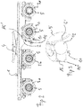
- FIG. 1 to 3 an embodiment of a heavy-duty transport vehicle 1 known per se and therefore not described in detail is shown, which has a chassis 2 with a number of wheel assemblies 3a-3d arranged one behind the other.
- a load bed 4 for the load to be transported is also arranged in a known manner.
- the figures do not show a coupling device such as a drawbar or a tow bar or a corresponding receptacle for it, by means of which the heavy-duty transport vehicle 1 can be connected to a towing or pushing vehicle, ie a drive vehicle (not shown).
- This towing or pushing vehicle has a drive device (also not shown), which is used to drive the towing or pushing vehicle and provides a permanent first drive power, so that this towing or pushing vehicle is movable via the coupling device mechanically connected to this heavy-duty transport vehicle 1.
- the heavy-duty transport vehicle 1 is moved by the vehicle-external, permanent drive device of the drive vehicle.
- the heavy-duty transport vehicle 1 is a towed vehicle.
- the same considerations also apply to a heavy-duty transport vehicle 1 pulled by a corresponding drive vehicle.
- a temporary drive device 10 which can be brought into engagement at least temporarily with at least one wheel assembly, in the case shown here as an example with the wheel assembly 3c, so that this wheel assembly 3c driven in rotation and so the heavy-duty transport vehicle 1 can be moved.
- this temporary drive device 10 is designed in such a way that an official approval that has already been granted and is required for operation of the heavy-duty transport vehicle 1 on public traffic areas is retained: Heavy-duty transport vehicles of the type described require this because of the Transported high loads are subject to a technical inspection and the official approval granted on the basis of the same basically prohibits any modifications, especially to the chassis and/or the wheel assemblies.
- the drive device 10 which can be brought temporarily into engagement with a wheel arrangement, can be operated by a drive unit 11 (not shown in detail) (see figure 1 , in figure 2 not shown) driven friction wheel 12 which is brought into operative engagement with a tread 5' of a tire 5 of the wheel assembly 3c will.
- This non-positive, here frictional, connection between the friction wheel 12 and the tire 5 converts a rotational movement of the friction wheel 12 into a rotational movement of the tire 5 and thus of the wheel arrangement 3c.
- Drive device 10 is preferably configured in such a way that it can be easily assembled and disassembled from chassis 2, so that when drive device 10 is assembled, friction wheel 12 is in operative engagement with wheel assembly 3c, thereby enabling heavy-duty transport vehicle 1 to maneuver while a drive device 10 removed from the chassis 2 of the heavy-duty transport vehicle 1, not only is the active engagement removed, but the heavy-duty transport vehicle 1 is in its configuration on which the technical acceptance is based. However, it is not absolutely necessary to assemble and disassemble the drive device 10 as described above.
- the drive device 10 may well be sufficient for the drive device 10 to be configured in such a way that the friction wheel 12 can be moved towards and away from the wheel arrangement 3c, in particular can be pivoted away again, so that in the moved-away position there is no active engagement between the friction wheel 12 and wheel assembly 3c is more.
- the drive device 10 can be attached to the chassis 2 easily and without major interventions in the structure of the chassis 2, so that there are no structural changes to the chassis 2 and thus to the heavy-duty transport vehicle 1 that are relevant to approval. It is advantageous that chassis 2 of heavy-duty transport vehicles 1 can also be retrofitted in this way, that these can also be retrofitted later for use with the drive device 10 described.
- the drive device 10 has a carrier 15 which can be mounted with its first end 15' on the chassis 2 and which carries the friction wheel 12 at its second end 15".
- a carrier 15 is easy to mount on the chassis 2 and to lose weight again
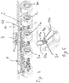
- FIG. 4 and 5 is the heavy-duty transport vehicle 1 of Figures 1 to 3 shown together with a second embodiment of a drive device 10.
- the second drive device 10 uses a chain drive instead of the friction wheel 12 of the first drive device 10 to produce a non-positive connection between the drive device 10 and the wheel arrangement 3c.
- a gear wheel (not shown) is arranged on the wheel axle of the wheel arrangement 3c. This gear wheel is driven by the drive unit 11, which is figure 4 is arranged on the load bed 4 by way of example.
- this arrangement of the drive unit 11 is also only of an exemplary nature here. It is possible for the gear wheel provided on the wheel arrangement 3c and the drive unit 11 to be connected directly by means of a corresponding drive chain. However, preference is given to the Figures 4 and 5 shown embodiment, in which the drive unit 11 and the gear wheel of the wheel assembly 3c are connected to each other by means of a chain drive 21.
- two concentrically arranged gear wheels 21a and 21b are provided on the chassis 2 of the heavy-duty transport vehicle 1, the first gear wheel 21a being connected to the drive unit 11 by means of a first chain 22a and the second gear wheel 21b being connected to the wheel arrangement by means of a further chain 22b 3c arranged gear are connected.
- the heavy-duty transport vehicle 1 is a towed or pushed heavy-duty transport vehicle 1, which is primarily pulled or pushed by a towing or pushing vehicle, with the towing or pushing vehicle having a drive device that has a permanent Provides drive power for the heavy-duty transport vehicle has available.
- the drive device that provides permanent drive power is integrated into the latter, that is to say it is designed as a drive device inside the vehicle. No devices such as a drawbar are therefore required to move this heavy-duty transport vehicle.
- the term "heavy-duty transport vehicle” used in the following claims should therefore include both a pulled or pushed heavy-duty transport vehicle and a self-propelled, ie self-propelled, heavy-duty transport vehicle.
Landscapes
- Engineering & Computer Science (AREA)
- Health & Medical Sciences (AREA)
- Public Health (AREA)
- Transportation (AREA)
- Mechanical Engineering (AREA)
- Arrangement And Driving Of Transmission Devices (AREA)
Applications Claiming Priority (2)
| Application Number | Priority Date | Filing Date | Title |
|---|---|---|---|
| DE102020004086.1A DE102020004086B3 (de) | 2020-07-07 | 2020-07-07 | Schwerlast-Transportfahrzeug mit einer Antriebseinrichtung |
| DE202020002904.1U DE202020002904U1 (de) | 2020-07-07 | 2020-07-07 | Schwerlast-Transportfahrzeug mit einer Antriebseinrichtung |
Publications (1)
| Publication Number | Publication Date |
|---|---|
| EP3936384A1 true EP3936384A1 (fr) | 2022-01-12 |
Family
ID=76829245
Family Applications (1)
| Application Number | Title | Priority Date | Filing Date |
|---|---|---|---|
| EP21020356.8A Withdrawn EP3936384A1 (fr) | 2020-07-07 | 2021-07-07 | Véhicule de transport des charges lourdes doté d'un dispositif d'entraînement |
Country Status (1)
| Country | Link |
|---|---|
| EP (1) | EP3936384A1 (fr) |
Citations (10)
| Publication number | Priority date | Publication date | Assignee | Title |
|---|---|---|---|---|
| FR1238041A (fr) * | 1958-10-08 | 1960-08-05 | Véhicule automobile-élévateur | |
| US3019927A (en) * | 1958-12-05 | 1962-02-06 | Jr Daniel J Sheehan | Method and apparatus for transporting beams |
| DE102010023307A1 (de) | 2010-06-10 | 2011-12-15 | Scheuerle Fahrzeugfabrik Gmbh | Antriebseinheit für ein modulares, selbstangetriebenes Schwerlastfahrzeug |
| US8646753B2 (en) * | 2011-05-27 | 2014-02-11 | Roger L. Ross | System for transporting shipping containers |
| DE102014007979A1 (de) | 2014-06-04 | 2015-12-17 | Scheuerle Fahrzeugfabrik Gmbh | Fahrzeug-Verbund mit mehreren angetriebenen Fahrzeugmodulen |
| DE102016203577A1 (de) | 2016-03-04 | 2017-09-07 | Goldhofer Ag | Nutzfahrzeug, insbesondere Schwerlastfahrzeug und Radbaugruppe für ein derartiges Nutzfahrzeug |
| US20170305259A1 (en) * | 2014-10-17 | 2017-10-26 | Lohr Electromecanique | Hybrid Vehicle And Vehicle Hybridization Method |
| DE202016105321U1 (de) | 2016-08-25 | 2017-11-28 | Carman Enterprise Co., Ltd. | Rangierantriebssystem sowie Fahrzeug mit einem solchen |
| WO2018152406A1 (fr) * | 2017-02-17 | 2018-08-23 | Hyliion Inc. | Unité de tracteur avec stockage d'énergie de freinage par récupération embarqué pour une opération hvac à l'arrêt sans ralenti du moteur |
| EP3423322A1 (fr) * | 2016-03-02 | 2019-01-09 | Carbyne Enterprises, Inc. | Système de conversion de véhicule hybride |
-
2021
- 2021-07-07 EP EP21020356.8A patent/EP3936384A1/fr not_active Withdrawn
Patent Citations (10)
| Publication number | Priority date | Publication date | Assignee | Title |
|---|---|---|---|---|
| FR1238041A (fr) * | 1958-10-08 | 1960-08-05 | Véhicule automobile-élévateur | |
| US3019927A (en) * | 1958-12-05 | 1962-02-06 | Jr Daniel J Sheehan | Method and apparatus for transporting beams |
| DE102010023307A1 (de) | 2010-06-10 | 2011-12-15 | Scheuerle Fahrzeugfabrik Gmbh | Antriebseinheit für ein modulares, selbstangetriebenes Schwerlastfahrzeug |
| US8646753B2 (en) * | 2011-05-27 | 2014-02-11 | Roger L. Ross | System for transporting shipping containers |
| DE102014007979A1 (de) | 2014-06-04 | 2015-12-17 | Scheuerle Fahrzeugfabrik Gmbh | Fahrzeug-Verbund mit mehreren angetriebenen Fahrzeugmodulen |
| US20170305259A1 (en) * | 2014-10-17 | 2017-10-26 | Lohr Electromecanique | Hybrid Vehicle And Vehicle Hybridization Method |
| EP3423322A1 (fr) * | 2016-03-02 | 2019-01-09 | Carbyne Enterprises, Inc. | Système de conversion de véhicule hybride |
| DE102016203577A1 (de) | 2016-03-04 | 2017-09-07 | Goldhofer Ag | Nutzfahrzeug, insbesondere Schwerlastfahrzeug und Radbaugruppe für ein derartiges Nutzfahrzeug |
| DE202016105321U1 (de) | 2016-08-25 | 2017-11-28 | Carman Enterprise Co., Ltd. | Rangierantriebssystem sowie Fahrzeug mit einem solchen |
| WO2018152406A1 (fr) * | 2017-02-17 | 2018-08-23 | Hyliion Inc. | Unité de tracteur avec stockage d'énergie de freinage par récupération embarqué pour une opération hvac à l'arrêt sans ralenti du moteur |
Similar Documents
| Publication | Publication Date | Title |
|---|---|---|
| DE102020211013A1 (de) | Angetriebene achse für ein arbeitsfahrzeug mit zwillingsrädern | |
| EP3152102B1 (fr) | Ensemble de véhicules comprenant plusieurs modules de véhicule entraînés | |
| EP3426545B1 (fr) | Unité d'entraînement et procédé d'entraînement | |
| EP3216333B1 (fr) | Tracteur agricole comprenant un véhicule tracteur et une remorque | |
| DE102011003791A1 (de) | System zum automatischen Einstellen eines Spaltraumes zwischen einem Motorwagen und einem daran angekuppelten Anhänger | |
| DE102011080236A1 (de) | Antriebsvorrichtung für ein einzelnes Rad eines Kraftfahrzeugs | |
| EP2562442B1 (fr) | Boîte de vitesse, en particulier pour une chaîne de transmission dans des véhicules automobiles, des véhicules sur rail ou analogues | |
| DE102010040883A1 (de) | Verteilergetriebe | |
| WO2020114548A1 (fr) | Actionneur de frein de stationnement à intégrer dans une transmission de véhicule | |
| DE102014007979B4 (de) | Fahrzeug-Verbund mit mehreren angetriebenen Fahrzeugmodulen | |
| DE102016221796A1 (de) | Hybridgetriebe und Hybridantriebsstrang | |
| EP3096967B1 (fr) | Chaîne cinématique pour machine de travail mobile entraînée par moteur | |
| DE102020004086B3 (de) | Schwerlast-Transportfahrzeug mit einer Antriebseinrichtung | |
| EP2824019B1 (fr) | Unité d'entraînement pour un entraînement d'aide à la conduite | |
| DE102019202781A1 (de) | Verfahren zum Steuern einer Bewegung eines elektrisch angetriebenen Anhängers | |
| EP2080647A2 (fr) | Dispositif de transport sur rail | |
| DE102017003905A1 (de) | Achsgetriebesystem, Antriebsachsensystem und Kraftfahrzeug | |
| DE102020216271A1 (de) | Zugmaschinenverbund mit angetriebenem Anhänger | |
| EP2559581A2 (fr) | Système d'entraînement pour un véhicule automobile équipé d'un système de freinage agissant comme un différentiel à blocage | |
| DE112019007903T5 (de) | Untersetzungsgetriebebaugruppe | |
| DE202023103341U1 (de) | Elektrische Radsatzgetriebesysteme | |
| EP3480047A1 (fr) | Essieu de remorque entraîné centralement | |
| EP3628525B1 (fr) | Véhicule automobile doté d'un entraînement auxiliaire pour un essieu dirigeable | |
| DE102009051124A1 (de) | Antriebssystem für ein Elektroradfahrzeug | |
| DE202010005650U1 (de) | Hilfsfahrantrieb |
Legal Events
| Date | Code | Title | Description |
|---|---|---|---|
| PUAI | Public reference made under article 153(3) epc to a published international application that has entered the european phase |
Free format text: ORIGINAL CODE: 0009012 |
|
| STAA | Information on the status of an ep patent application or granted ep patent |
Free format text: STATUS: THE APPLICATION HAS BEEN PUBLISHED |
|
| AK | Designated contracting states |
Kind code of ref document: A1 Designated state(s): AL AT BE BG CH CY CZ DE DK EE ES FI FR GB GR HR HU IE IS IT LI LT LU LV MC MK MT NL NO PL PT RO RS SE SI SK SM TR |
|
| B565 | Issuance of search results under rule 164(2) epc |
Effective date: 20211129 |
|
| STAA | Information on the status of an ep patent application or granted ep patent |
Free format text: STATUS: REQUEST FOR EXAMINATION WAS MADE |
|
| 17P | Request for examination filed |
Effective date: 20220712 |
|
| RBV | Designated contracting states (corrected) |
Designated state(s): AL AT BE BG CH CY CZ DE DK EE ES FI FR GB GR HR HU IE IS IT LI LT LU LV MC MK MT NL NO PL PT RO RS SE SI SK SM TR |
|
| STAA | Information on the status of an ep patent application or granted ep patent |
Free format text: STATUS: EXAMINATION IS IN PROGRESS |
|
| 17Q | First examination report despatched |
Effective date: 20230724 |
|
| STAA | Information on the status of an ep patent application or granted ep patent |
Free format text: STATUS: THE APPLICATION HAS BEEN WITHDRAWN |
|
| 18W | Application withdrawn |
Effective date: 20240322 |