EP2824264B1 - Ferrure pour une fenêtre, une porte ou analogue avec un battant basculant et coulissant - Google Patents
Ferrure pour une fenêtre, une porte ou analogue avec un battant basculant et coulissant Download PDFInfo
- Publication number
- EP2824264B1 EP2824264B1 EP13175461.6A EP13175461A EP2824264B1 EP 2824264 B1 EP2824264 B1 EP 2824264B1 EP 13175461 A EP13175461 A EP 13175461A EP 2824264 B1 EP2824264 B1 EP 2824264B1
- Authority
- EP
- European Patent Office
- Prior art keywords
- control
- fitting
- sash
- control pin
- actuating element
- Prior art date
- Legal status (The legal status is an assumption and is not a legal conclusion. Google has not performed a legal analysis and makes no representation as to the accuracy of the status listed.)
- Active
Links
Images


Classifications
-
- E—FIXED CONSTRUCTIONS
- E05—LOCKS; KEYS; WINDOW OR DOOR FITTINGS; SAFES
- E05D—HINGES OR SUSPENSION DEVICES FOR DOORS, WINDOWS OR WINGS
- E05D15/00—Suspension arrangements for wings
- E05D15/06—Suspension arrangements for wings for wings sliding horizontally more or less in their own plane
- E05D15/10—Suspension arrangements for wings for wings sliding horizontally more or less in their own plane movable out of one plane into a second parallel plane
- E05D15/1005—Suspension arrangements for wings for wings sliding horizontally more or less in their own plane movable out of one plane into a second parallel plane the wing being supported on arms movable in horizontal planes
- E05D15/1013—Suspension arrangements for wings for wings sliding horizontally more or less in their own plane movable out of one plane into a second parallel plane the wing being supported on arms movable in horizontal planes specially adapted for windows
- E05D15/1015—Suspension arrangements for wings for wings sliding horizontally more or less in their own plane movable out of one plane into a second parallel plane the wing being supported on arms movable in horizontal planes specially adapted for windows with an intermediate tilt position
-
- E—FIXED CONSTRUCTIONS
- E05—LOCKS; KEYS; WINDOW OR DOOR FITTINGS; SAFES
- E05Y—INDEXING SCHEME ASSOCIATED WITH SUBCLASSES E05D AND E05F, RELATING TO CONSTRUCTION ELEMENTS, ELECTRIC CONTROL, POWER SUPPLY, POWER SIGNAL OR TRANSMISSION, USER INTERFACES, MOUNTING OR COUPLING, DETAILS, ACCESSORIES, AUXILIARY OPERATIONS NOT OTHERWISE PROVIDED FOR, APPLICATION THEREOF
- E05Y2900/00—Application of doors, windows, wings or fittings thereof
- E05Y2900/10—Application of doors, windows, wings or fittings thereof for buildings or parts thereof
- E05Y2900/13—Type of wing
- E05Y2900/148—Windows
Definitions
- the invention relates to a fitting for a window, a door or the like with a tiltable and sliding sash, wherein a stay rod of the fitting can be connected at one end at least indirectly to the sash and at the other end at least indirectly to a glider and/or carriage, and the fitting comprises a control part which has a control contour in or on which a control pin of the stay rod is guided.
- Such a fitting is, for example, from the EP 1 959 080 A2
- This known fitting is designed to park a sash from a closed position, in which the sash rests against the frame, parallel to the main plane of the frame and then move it. When the sash is parked, it undergoes a pivoting movement whose radius is determined by the stay. Thus, the fitting does not move the sash perpendicular to the main plane. of the frame, but rather in an arcuate position. The arcuate position requires that the sash is offset from the frame in the stowed position. Tilting the sash, in which the sash is pivoted away from the frame on one side and remains attached to the frame on the opposite side, is therefore not possible with the conventional hardware.
- the object of the invention is therefore to provide a fitting that allows both sliding and tilting of a sash of a window, door, or the like around a horizontal pivot axis.
- the design of the fitting according to the invention enables both tilting of the sash - namely when the control pin is moved in the first control section or on the first control section - and displacement of the sash - namely when the control pin is moved in the second control section or on the second control section.
- the control part also has a bolt which, in a blocking position, limits or prevents the movement of the control pin along the control contour.
- the bolt can be moved into a release position by an actuating element of the fitting which is at least indirectly rotatably connected to the stay link, in which position it does not limit or prevent the movement of the control pin.
- the bolt serves as a stop against which the control pin moves when the sash is closed if the sash has been moved parallel to the frame and is now to be closed, i.e. if the sash is moved from a sliding position to a closed position.
- the bolt acting as a stop enables a controlled movement from the sliding position to the closed position.
- the control pin of the stay link can move more freely within the control contour.
- the stay link thus receives the necessary Clearance to allow the sash to tilt and open.
- the fitting thus enables both a controlled movement of the sash from the closed position to the tilt and open position and back to the closed position, as well as a controlled movement from the closed position to the sliding position and back to the closed position.
- the fitting can be provided for at least indirectly connecting any side of a sash to the frame.
- the fitting according to the invention is provided on the top side, and a conventional fitting, which enables a pure parking and sliding movement of the sash, is provided on the underside of the sash.
- the conventional fitting is preferably connected to two carriages. This allows the sash to be moved from the closed position to the sliding position and to be moved parallel to the main frame plane.
- the upper fitting can have carriages or gliders. The sash can be tilted away from the frame at the top side from the closed position.
- the latch In the blocking position, the latch is arranged between the first control section and the second control section. In the blocking position, the latch can thus prevent movement of the control pin from the second control section into the first control section. In contrast, when the latch is in the release position, the control pin can move from the second control section into the first control section.
- the actuating element is preferably formed or arranged on a slider and/or carriage. This allows the fitting to be the sliding position parallel to the main plane of the frame.
- the actuating element can be designed, at least in sections, in the form of a plate-shaped cover of the control part in order to achieve a space-saving fitting.
- the latch can be moved from the blocking position to the release position by the actuating element against the force of a return element. This causes the latch to automatically return to the blocking position after actuation by the return element. In this case, no means for returning the latch to the blocking position need to be provided on the actuating element, thus simplifying the design of the actuating element.
- the fitting can be designed to be particularly simple if the bolt is attached to a control part body of the control part via the return element.
- the bolt is designed in the form of a threshold, which has a bevel and/or curvature on a first side that interacts with the control pin.
- the bolt can be designed as a stop for the control pin on a second side opposite the first side. If the control pin is moved against the first side during a closing movement from the tilt-open position, it displaces the bolt or pushes it away. If, however, the control pin is moved against the second side of the bolt during a closing movement from the sliding position, it cannot displace the bolt.
- the second side is preferably designed in the form of a wall.
- Such a design of the bolt ensures that the control pin can always pass the bolt in a first direction - namely, toward the first side of the bolt - while in the second direction - namely, toward the second side of the bolt - it can only pass the bolt when the actuating element releases the bolt.
- the bolt is preferably arranged in the fitting so that the control pin is always The fitting can move from the tilt-open position to the closed position, but only when released by the actuating element. This ensures that the sash can be moved in a controlled manner from the sliding position to the closed position, as well as from the tilt-open position to the closed position.
- the control part can have a locking element for reversibly and releasably fixing the position of the control pin in the tilt-open position.
- the locking element is preferably designed in the form of a spring. The locking element secures the tilt-open position of the fitting by holding the control pin in a defined position. The tilted sash cannot thus be moved into the closed position by a draft, but must be deliberately closed against the resistance of the locking element.
- the actuating element has a guide contour in or on which the control pin is guided.
- the actuating element can thus be moved relative to the control pin in a simple and defined manner.
- the scissor stay preferably has a projection arm for tilting the sash and a control arm rotatably mounted on the projection arm.
- the projection arm at least indirectly establishes the connection between the sash and the frame, while the control arm serves to limit the movement of the projection arm.
- the extension arm is rotatably connected to the actuating element.
- the actuating element can thus be directly
- the opening scissors can be controlled. This significantly simplifies the design of the fitting.
- control pin is formed or arranged on the control arm.
- control pin can also be formed or arranged on the extension arm, and the control arm can be rotatably coupled to the actuating element.
- the invention further relates to a window, a door or the like with a fitting as described above.
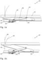
- Fig. 1a shows a fitting 10 according to the invention for connecting a sash of a window, a door or the like to a frame of this window, door, or the like.
- the fitting 10 has a sash part 12 and a control part (control block) 14.
- the sash part 12 is part of a sash or at least attachable to a sash.
- the control part 14 is part of a frame or at least attachable to a frame.
- the wing part 12 can be attached directly and immovably to a wing and the control part 14 can be attached directly and immovably to a frame.
- a stay scissor 16 To control the movement of the sash from a closed position into a parallel sliding position or a tilt-open position, a stay scissor 16 is provided.
- the stay scissor 16 comprises a stay arm 18 and a control arm 20.
- the control arm 20 is rotatably mounted on the stay arm 18 at one end via a first bearing 22.
- the control arm 20 has a control pin 24.
- the control pin 24 is guided in a control contour 26 in the form of a control groove of the control part 14.
- Fig. 1b shows the fitting 10 when the sash is opened, i.e., when the sash part 12 is set aside from the control part 14.
- the sash or the sash part 12 can be spaced apart from the frame or the control part 14 along two "paths."
- a first path 28 runs perpendicular to the main frame plane of the window, door, or the like. If the sash part 12 is set aside along the first path 28, the sash can be brought into the tilt-open position.
- a second path 30 runs in an arc. This arc is described when the sash or the sash part 12 is set aside in a parallel, set-back position, from which the sash can be moved. When the sash is moved, the control pin 24 leaves the control part 14.
- Whether the sash or sash part 12 follows the first path 28 or the second path 30 depends on the switching position of a connecting rod fitting (not shown). If the connecting rod fitting is in the "sliding opening" switching position, the sash can be parked parallel, i.e., it takes the second path 30. If the connecting rod fitting is in the "tilt opening” switching position, the sash is held against the fixed frame at the bottom, and the sash can take the first path 28 at the top, where the fitting 10 is located.
- the first path 28 and the second path 30 are in a first section 32 which the wing part 12 defines between the Fig. 1a and the Fig. 1b shown position, are approximately congruent. Only in the further course of movement of the wing part 12 do the paths 28 and 30 differ significantly. This is shown in Fig. 1c and Fig. 1d shown.
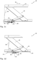
- Fig. 1c shows the fitting 10 in the sliding position.
- the sash part 12 has been moved along the second path 30.
- the user can pull the sash or sash part 12 in the direction of a first arrow 34.
- the control pin 24 is thereby pulled out of the control contour 26.
- the control pin 24 In the Fig. 1c In the sliding position shown, the control pin 24 cannot be moved into a first control section 36 of the control contour 26. The movement of the control pin 24 is rather limited to a second control section 38 of the control contour 26. The control pin 24 is prevented from moving from the second control section 38 into the first control section 36 by a bolt 40. In other words, the bolt 40 serves as a stop for the control pin 24. This function as a stop plays an important role when closing the sash from the sliding position into the closed position, that is to say when the sash part 12 is moved in the opposite direction of the first arrow 34 from the Fig. 1c shown position into the Fig. 1a shown position. During this movement, the control pin 24 is inserted into the control contour 26 and then strikes the bolt 40, so that the sash part 12 is forced by the extension scissors 16 into a controlled, arcuate closing movement along the second path 30.
- Fig. 1d shows the fitting 10 in the tilt-open position.
- the control pin 24 requires appropriate play in the control part 14:
- the control pin 24 must be movable from the second control section 38 into the first control section 36 of the control contour 26.
- the latch 40 must release the movement of the control pin 24. This release is effected by an actuating element 42.
- the actuating element 42 is moved for this purpose by the extension arm 18, which is rotatably connected to the actuating element 42 via a second bearing 44.
- the design of the control part 14 and the actuating element 42 for actuating the latch 40 is explained below. Fig. 2a, 2b and Fig. 3 visible.
- Fig. 2a shows the control unit 14. From Fig. 2a It can be seen that the latch 40 is arranged on a control part body 47 of the control part 14 via a return element 46.
- the return element 46 is essentially designed in the form of a leaf spring and presses the latch 40 against the control part body 47.
- the return element 46 can also be designed in another form, in particular in the form of a cylindrical compression spring.
- the latch 40 divides the control contour 26 into the first Control section 36, in which the control pin 24 (see Fig. 1a ) is moved during the transition from a closed position to a tilt-open position, and the second control section 38, in which the control pin 24 is moved during the transition from a closed position to a sliding position.
- the first control section 36 is angled to the second control section 38, wherein the first control section 36 extends parallel to the longitudinal direction of the control part 14 or parallel to the circumferential direction of the fold, and the second control section 38 is aligned transversely thereto.
- the bolt 40 of the control part 14 is designed in the form of a threshold, which has a first side 48 and a second side 50.
- the first side 48 is designed in the form of a slope
- the second side 50 in the form of a vertical stop. If the control pin 24 (see Fig. 1d ) in the direction of a second arrow 52 towards the first side 48, it displaces the threshold 40 downwards, i.e. in the direction of a third arrow 54. If, on the other hand, the control pin 24 is moved in the direction of a fourth arrow 56 towards the second side 50, the control pin cannot displace the bolt 40.
- a movement in the direction of the second arrow 52 corresponds to a movement from the tilt opening position (see Fig. 1d ) into the closed position (see Fig. 1a ), while a movement in the direction of the fourth arrow 56 corresponds to a movement from the sliding position (see Fig. 1c ) into the closed position (see Fig. 1a ).
- the described design of the latch 40 thus ensures that the fitting 10 can always be moved from the tilt-open position to the closed position.
- a controlled pivoting of the sash from the sliding position to the closed position is enabled, since the control pin 24 cannot itself displace the latch 40 in the direction of the fourth arrow 56.
- the control pin 24 In the tilt opening position (see Fig. 1d ), the control pin 24 is held in place by a reversibly releasable locking element 58 in the form of a leaf spring. The wing cannot therefore be moved from the tilted open position to the closed position by a draft of air alone (see Fig. 1a ) are transferred.
- Fig. 3 shows a section of this actuating element 42.
- the actuating element 42 is formed in one piece and has a guide contour 60 in which the control pin 24 is guided (see Fig. 1b ).
- the Fig. 3 The front section of the actuating element 42 shown is designed as a slider, so that the wing (see Fig. 1a ) can be moved parallel to the frame.
- the fitting 10 can be connected directly or indirectly, i.e. at least indirectly, to a slider for sliding the sash.
- the actuating element 42 has an actuating projection 62.
- Another similarly designed actuating projection is arranged on the opposite side, Fig. 3 non-visible side of the actuating element 42.
- the actuating projection 62 can - as an alternative to the one-piece embodiment shown - be arranged in the form of an additional component on the actuating element 42 or on the slider and/or carriage.
- the actuating projection 62 is to operate the bolt 40 (see Fig. 2b ) as can be seen from the following Fig. 4a-4d is evident.
- Fig. 4a shows the fitting 10 in the closed position according to Fig. 1a
- the bolt 40 is pressed by the return element 46 against the control part body 47.
- the bolt 40 forms a stop which is insurmountable for the control pin 24 (see also Fig. 1a ).
- the bolt 40 is in a blocking position.
- Fig. 4b shows the fitting 10 in the partially opened position according to Fig. 1b .
- the actuating element 42 has been displaced by the extension scissors 16 in the direction of a fifth arrow 64.
- the actuating projection 62 displaces the bolt 40 against the resistance of the return element 46 and thereby allows the control pin 24 (see also Fig. 1b ) passing through the bolt 40.
- the bolt 40 is in a release position.
- the bolt 40 and the actuating projection 62 have run-up slopes. This reduces the resistance between the actuating element 42 and the bolt 40.
- the fitting 10 is therefore easy to handle for the user.
- the bolt 40 and/or the actuating projection 62 have a sliding surface to further reduce the resistance.
- Fig. 4c shows the fitting 10 in the sliding position according to Fig. 1c .
- the actuating element 42 has been moved further in the direction of the fifth arrow 64, so that the actuating projection 62 has already passed the bolt 40.
- the control pin 24 can therefore no longer overcome the bolt 40.
- the bolt 40 thus serves as a stop during the transition from the parallel to the frame "Sliding" the sash into the pivoting movement to the final closing position (see Fig. 1a ).
- Fig. 4d shows the fitting 10 in the tilt opening position according to Fig. 1d .
- the actuating element 42 is displaced completely in the direction of the fifth arrow 64, so that the bolt 40 is not actuated by the actuating projection 62.
- the control pin 24 can actuate the bolt 40 (see Fig. 1d ) automatically - as described above - to return to the closed position according to Fig. 1a to get there.
- the invention relates to a fitting for connecting a sash of a window, door, or the like to its frame.
- the fitting enables the sash—depending on the coupling of the sash to the frame by another fitting—to be either tilted or positioned parallel to the main plane of the frame and then moved parallel to the main plane of the frame.
- the fitting has a stay rod, which is guided via a control pin in a control part connectable to the frame.
- a bolt of the control part limits the travel of the control pin during the closing movement of the sash from a position displaced parallel to the main plane of the frame. This enables a controlled and defined arcuate closing movement.
- an actuating element connected to the stay rod enables the displacement of the bolt when the sash is to be tilted, in order to allow greater movement of the control pin and thus a straight pivoting of the sash into a tilt-open position.
- the actuating element is preferably designed as a slider for moving the wing or is connected to a slider for moving the wing.
Landscapes
- Engineering & Computer Science (AREA)
- Mechanical Engineering (AREA)
- Power-Operated Mechanisms For Wings (AREA)
- Wing Frames And Configurations (AREA)
- Extensible Doors And Revolving Doors (AREA)
Claims (11)
- Ferrure (10) dévolue à une fenêtre, à une porte ou à un objet similaire muni(e) d'un vantail basculant et coulissant,un ensemble articulé (16) de déploiement de ladite ferrure (10) pouvant être relié au vantail par une extrémité, au moins de manière indirecte, et à un coulisseau et/ou à un chariot par l'autre extrémité, au moins de manière indirecte, et ladite ferrure (10) incluant une partie de commande (14)pourvue d'un profil de commande (26) dans lequel, ou sur lequel un tenon de commande (24) de l'ensemble articulé de déploiement (16) est guidé,sachant queledit profil de commande (26) comprend une première zone de commande (36) et une seconde zone de commande (38), le tenon de commande (24) étant mû dans, ou sur ladite première zone de commande (36), en vue de l'ouverture du vantail par basculement, et dans, ou sur ladite seconde zone de commande (38) en vue de l'ouverture dudit vantail par coulissement,caractérisée par le faitque la partie de commande (14) comporte un verrou (40) qui limite ou empêche le mouvement du tenon de commande (24) le long du profil de commande (26), dans une position de blocage, et ledit verrou (40) peut être mû, par l'intermédiaire d'un élément (42) d'actionnement de la ferrure (10) qui est relié à l'ensemble articulé de déploiement (16) avec faculté de rotation au moins indirecte, vers une position de libération dans laquelle il ne limite, ni n'empêche ledit mouvement du tenon de commande (24), étant précisé queledit verrou (40) est interposé entre la première zone de commande (36) et la seconde zone de commande (38) dans ladite position de blocage.
- Ferrure selon la revendication 1, caractérisée par le fait que l'élément d'actionnement (42) est façonné ou disposé sur un coulisseau et/ou sur un chariot.
- Ferrure selon l'une des revendications précédentes, caractérisée par le fait que le verrou (40) peut être mû de la position de blocage à la position de libération par l'intermédiaire de l'élément d'actionnement (42), en opposition à la force d'un élément de rappel (46).
- Ferrure selon la revendication 3, caractérisée par le fait que le verrou (40) est relié, par l'intermédiaire de l'élément de rappel (46), à un corps (47) de la partie de commande (14).
- Ferrure selon l'une des revendications précédentes, caractérisée par le fait que le verrou (40) est conçu sous la forme d'un chenal présentant, sur un premier côté (48), un biseau et/ou une courbure coopérant avec le tenon de commande (24).
- Ferrure selon l'une des revendications précédentes, caractérisée par le fait que la partie de commande (14) est dotée d'un élément d'arrêt (58) affecté au verrouillage à demeure, réversible et libérable, de l'emplacement du tenon de commande (24) dans une position d'ouverture par basculement.
- Ferrure selon l'une des revendications précédentes, caractérisée par le fait que l'élément d'actionnement (42) est nanti d'un profil de guidage (60) dans, ou sur lequel le tenon de commande (24) est guidé.
- Ferrure selon l'une des revendications précédentes, caractérisée par le fait que l'ensemble articulé de déploiement (16) comprend un bras d'extension (18), affecté au débrayage du vantail, et un bras de commande (20) implanté sur ledit bras d'extension (18) avec faculté de rotation.
- Ferrure selon la revendication 8, caractérisée par le fait que le bras d'extension (18) est relié à l'élément d'actionnement (42) avec faculté de rotation.
- Ferrure selon la revendication 8 ou 9, caractérisée par le fait que le tenon de commande (24) est façonné ou disposé sur le bras de commande (20).
- Fenêtre, porte ou objet similaire équipé(e) d'une ferrure (10) conforme à l'une des revendications précédentes.
Priority Applications (4)
| Application Number | Priority Date | Filing Date | Title |
|---|---|---|---|
| EP13175461.6A EP2824264B1 (fr) | 2013-07-08 | 2013-07-08 | Ferrure pour une fenêtre, une porte ou analogue avec un battant basculant et coulissant |
| RU2016103593A RU2016103593A (ru) | 2013-07-08 | 2014-06-13 | Фурнитура для окна, двери или т.п. с откидно-сдвижной створкой |
| CN201480038645.2A CN105358782B (zh) | 2013-07-08 | 2014-06-13 | 包括可翻转和可滑移的翼扇的窗户、门或类似件的配件 |
| PCT/EP2014/062350 WO2015003872A1 (fr) | 2013-07-08 | 2014-06-13 | Ferrure pour une fenêtre, une porte ou analogue comportant un vantail basculant ou coulissant |
Applications Claiming Priority (1)
| Application Number | Priority Date | Filing Date | Title |
|---|---|---|---|
| EP13175461.6A EP2824264B1 (fr) | 2013-07-08 | 2013-07-08 | Ferrure pour une fenêtre, une porte ou analogue avec un battant basculant et coulissant |
Publications (2)
| Publication Number | Publication Date |
|---|---|
| EP2824264A1 EP2824264A1 (fr) | 2015-01-14 |
| EP2824264B1 true EP2824264B1 (fr) | 2025-06-04 |
Family
ID=48745826
Family Applications (1)
| Application Number | Title | Priority Date | Filing Date |
|---|---|---|---|
| EP13175461.6A Active EP2824264B1 (fr) | 2013-07-08 | 2013-07-08 | Ferrure pour une fenêtre, une porte ou analogue avec un battant basculant et coulissant |
Country Status (4)
| Country | Link |
|---|---|
| EP (1) | EP2824264B1 (fr) |
| CN (1) | CN105358782B (fr) |
| RU (1) | RU2016103593A (fr) |
| WO (1) | WO2015003872A1 (fr) |
Families Citing this family (5)
| Publication number | Priority date | Publication date | Assignee | Title |
|---|---|---|---|---|
| DE102014216722B4 (de) * | 2014-08-22 | 2016-12-29 | Roto Frank Ag | Steuerelement für eine Beschlaganordnung |
| DE102016202377A1 (de) | 2016-02-17 | 2017-08-17 | Roto Frank Ag | Beschlaganordnung zur Anbindung eines schieb- und kippbaren Flügels |
| DE102017217220B4 (de) * | 2017-09-27 | 2020-07-09 | Roto Frank Ag | In der Kippstellung verrastbarer und dennoch beim Schieb-Schließen leicht bewegbarer Beschlag für ein Fenster oder eine Tür |
| DE102023207976A1 (de) | 2023-08-21 | 2025-02-27 | Aug. Winkhaus SE & Co. KG | Beschlag für ein Schiebe-Kipp-Fenster |
| DE102023207979A1 (de) | 2023-08-21 | 2025-02-27 | Aug. Winkhaus SE & Co. KG | Beschlag für ein Schiebe-Kipp-Fenster |
Family Cites Families (5)
| Publication number | Priority date | Publication date | Assignee | Title |
|---|---|---|---|---|
| DE59201239D1 (de) * | 1992-10-27 | 1995-03-02 | Hautau Gmbh W | Beschlag für zwangsweise kipp- und parallel abstellbare und in der Schliessstellung bzw. der Kipp- oder Ausstellstellung verriegelbare Flügel. |
| DE10032897A1 (de) * | 2000-07-06 | 2002-01-24 | Weidtmann Wilhelm Kg | Kippbeschlag für Fenster, Türen o. dgl. |
| DE202008018015U1 (de) | 2007-02-15 | 2012-01-09 | Hautau Gmbh | Beschlag für einen Schiebeflügel |
| DE202008004033U1 (de) * | 2008-03-20 | 2009-07-30 | Siegenia-Aubi Kg | Beschlag für Horizontal-Schiebefenster |
| WO2009146782A1 (fr) * | 2008-06-06 | 2009-12-10 | Roto Frank Ag | Dispositif d’orientation pour une fenêtre, une porte ou similaire |
-
2013
- 2013-07-08 EP EP13175461.6A patent/EP2824264B1/fr active Active
-
2014
- 2014-06-13 WO PCT/EP2014/062350 patent/WO2015003872A1/fr not_active Ceased
- 2014-06-13 RU RU2016103593A patent/RU2016103593A/ru not_active Application Discontinuation
- 2014-06-13 CN CN201480038645.2A patent/CN105358782B/zh not_active Expired - Fee Related
Also Published As
| Publication number | Publication date |
|---|---|
| WO2015003872A1 (fr) | 2015-01-15 |
| EP2824264A1 (fr) | 2015-01-14 |
| CN105358782A (zh) | 2016-02-24 |
| RU2016103593A (ru) | 2017-08-11 |
| CN105358782B (zh) | 2018-03-16 |
Similar Documents
| Publication | Publication Date | Title |
|---|---|---|
| EP3622154B1 (fr) | Système de guidage pour le guidage d'un battant de porte | |
| DE2920581C2 (de) | Zusatzverriegelung, insbesondere Mittelverriegelung, für Fenster, Türen od.dgl. | |
| EP1959080B1 (fr) | Butée de battant mobile de fenêtre ou de porte | |
| EP2824264B1 (fr) | Ferrure pour une fenêtre, une porte ou analogue avec un battant basculant et coulissant | |
| EP3417134B1 (fr) | Ensemble ferrure pour le raccordement d'un battant coulissant et basculant | |
| EP2649259B1 (fr) | Ferrure facile d'utilisation pour ouvrant à déplacement parallèle | |
| DE102009050875B4 (de) | Vorrichtung zum Öffnen und Schließen von Fenstern an Wohnwagen, Wohnmobilen und dergleichen | |
| EP3034728B1 (fr) | Dispositif limiteur d'ouverture | |
| DE102009027242A1 (de) | Bewegliche Trennwand | |
| EP3420166B1 (fr) | Dispositif anti-relèvement pour un battant à coulissement parallèle se présentant sous forme d'oscillo-battant coulissant ou de battant coulissant | |
| DE102011085177A1 (de) | Antriebssystem für ein KFZ-Dachsystem | |
| EP3183408B1 (fr) | Élément de commande pour système de ferrure | |
| EP3162995B1 (fr) | PARTIE DE FERRURE D'UNE FERRURE POUR UN BATTANT D'UNE FENêTRE OU D'UNE PORTE | |
| EP2004448A1 (fr) | Systeme de deplacement d'un siege de vehicule | |
| EP0905343B1 (fr) | Agencement de fenêtre ou de porte | |
| DE102009031490A1 (de) | Schließfolgeregelung | |
| EP0980951B1 (fr) | Ferrure pour fenêtres, portes ou analogues pouvant être déplacés selon un plan parallèle et par la suite être coulissés. | |
| DE10013697A1 (de) | Feststellvorrichtung | |
| EP2787137B1 (fr) | Dispositif de verrouillage | |
| EP1965010B1 (fr) | Dispositif d'entraînement | |
| DE102017105596A1 (de) | Antriebsvorrichtung für einen Flügel, insbesondere für einen Tür- oder Fensterflügel, und Rahmen mit einer solchen Antriebsvorrichtung | |
| EP4253704B1 (fr) | Dispositif déflecteur à butée d'arrêt réglable et sécurité anti-effraction réglable ainsi que fenêtre ou porte dotée d'un tel dispositif déflecteur | |
| DE102007057218A1 (de) | Sicherungsvorrichtung für das Beschlagsystem von parallel abstellbaren Kippschiebetüren | |
| EP2896773B1 (fr) | Régulation de la séquence de fermeture | |
| EP2690241B1 (fr) | Armature pour une porte coulissante à fermeture parallèle ou une fenêtre coulissante à fermeture parallèle |
Legal Events
| Date | Code | Title | Description |
|---|---|---|---|
| 17P | Request for examination filed |
Effective date: 20130708 |
|
| AK | Designated contracting states |
Kind code of ref document: A1 Designated state(s): AL AT BE BG CH CY CZ DE DK EE ES FI FR GB GR HR HU IE IS IT LI LT LU LV MC MK MT NL NO PL PT RO RS SE SI SK SM TR |
|
| AX | Request for extension of the european patent |
Extension state: BA ME |
|
| PUAI | Public reference made under article 153(3) epc to a published international application that has entered the european phase |
Free format text: ORIGINAL CODE: 0009012 |
|
| R17P | Request for examination filed (corrected) |
Effective date: 20150706 |
|
| RBV | Designated contracting states (corrected) |
Designated state(s): AL AT BE BG CH CY CZ DE DK EE ES FI FR GB GR HR HU IE IS IT LI LT LU LV MC MK MT NL NO PL PT RO RS SE SI SK SM TR |
|
| STAA | Information on the status of an ep patent application or granted ep patent |
Free format text: STATUS: EXAMINATION IS IN PROGRESS |
|
| 17Q | First examination report despatched |
Effective date: 20161118 |
|
| RAP1 | Party data changed (applicant data changed or rights of an application transferred) |
Owner name: ROTO FRANK FENSTER- UND TUERTECHNOLOGIE GMBH |
|
| GRAP | Despatch of communication of intention to grant a patent |
Free format text: ORIGINAL CODE: EPIDOSNIGR1 |
|
| STAA | Information on the status of an ep patent application or granted ep patent |
Free format text: STATUS: GRANT OF PATENT IS INTENDED |
|
| INTG | Intention to grant announced |
Effective date: 20250203 |
|
| RIN1 | Information on inventor provided before grant (corrected) |
Inventor name: PETER, MARKUS Inventor name: BALCI, ERKAN Inventor name: GRAEF, DETLEF Inventor name: NYIKOS, TAMAS Inventor name: FINGERLE, STEFAN Inventor name: ISSLER, THORSTEN |
|
| GRAS | Grant fee paid |
Free format text: ORIGINAL CODE: EPIDOSNIGR3 |
|
| GRAA | (expected) grant |
Free format text: ORIGINAL CODE: 0009210 |
|
| STAA | Information on the status of an ep patent application or granted ep patent |
Free format text: STATUS: THE PATENT HAS BEEN GRANTED |
|
| AK | Designated contracting states |
Kind code of ref document: B1 Designated state(s): AL AT BE BG CH CY CZ DE DK EE ES FI FR GB GR HR HU IE IS IT LI LT LU LV MC MK MT NL NO PL PT RO RS SE SI SK SM TR |
|
| REG | Reference to a national code |
Ref country code: GB Ref legal event code: FG4D Free format text: NOT ENGLISH |
|
| REG | Reference to a national code |
Ref country code: CH Ref legal event code: EP |
|
| REG | Reference to a national code |
Ref country code: DE Ref legal event code: R096 Ref document number: 502013016590 Country of ref document: DE |
|
| REG | Reference to a national code |
Ref country code: IE Ref legal event code: FG4D Free format text: LANGUAGE OF EP DOCUMENT: GERMAN |
|
| REG | Reference to a national code |
Ref country code: NL Ref legal event code: MP Effective date: 20250604 |
|
| PG25 | Lapsed in a contracting state [announced via postgrant information from national office to epo] |
Ref country code: FI Free format text: LAPSE BECAUSE OF FAILURE TO SUBMIT A TRANSLATION OF THE DESCRIPTION OR TO PAY THE FEE WITHIN THE PRESCRIBED TIME-LIMIT Effective date: 20250604 Ref country code: ES Free format text: LAPSE BECAUSE OF FAILURE TO SUBMIT A TRANSLATION OF THE DESCRIPTION OR TO PAY THE FEE WITHIN THE PRESCRIBED TIME-LIMIT Effective date: 20250604 |
|
| PGFP | Annual fee paid to national office [announced via postgrant information from national office to epo] |
Ref country code: DE Payment date: 20250730 Year of fee payment: 13 |
|
| REG | Reference to a national code |
Ref country code: LT Ref legal event code: MG9D |
|
| PG25 | Lapsed in a contracting state [announced via postgrant information from national office to epo] |
Ref country code: GR Free format text: LAPSE BECAUSE OF FAILURE TO SUBMIT A TRANSLATION OF THE DESCRIPTION OR TO PAY THE FEE WITHIN THE PRESCRIBED TIME-LIMIT Effective date: 20250905 Ref country code: NO Free format text: LAPSE BECAUSE OF FAILURE TO SUBMIT A TRANSLATION OF THE DESCRIPTION OR TO PAY THE FEE WITHIN THE PRESCRIBED TIME-LIMIT Effective date: 20250904 |
|
| PG25 | Lapsed in a contracting state [announced via postgrant information from national office to epo] |
Ref country code: PL Free format text: LAPSE BECAUSE OF FAILURE TO SUBMIT A TRANSLATION OF THE DESCRIPTION OR TO PAY THE FEE WITHIN THE PRESCRIBED TIME-LIMIT Effective date: 20250604 |
|
| PG25 | Lapsed in a contracting state [announced via postgrant information from national office to epo] |
Ref country code: BG Free format text: LAPSE BECAUSE OF FAILURE TO SUBMIT A TRANSLATION OF THE DESCRIPTION OR TO PAY THE FEE WITHIN THE PRESCRIBED TIME-LIMIT Effective date: 20250604 |
|
| PG25 | Lapsed in a contracting state [announced via postgrant information from national office to epo] |
Ref country code: HR Free format text: LAPSE BECAUSE OF FAILURE TO SUBMIT A TRANSLATION OF THE DESCRIPTION OR TO PAY THE FEE WITHIN THE PRESCRIBED TIME-LIMIT Effective date: 20250604 |
|
| PG25 | Lapsed in a contracting state [announced via postgrant information from national office to epo] |
Ref country code: RS Free format text: LAPSE BECAUSE OF FAILURE TO SUBMIT A TRANSLATION OF THE DESCRIPTION OR TO PAY THE FEE WITHIN THE PRESCRIBED TIME-LIMIT Effective date: 20250904 |
|
| PG25 | Lapsed in a contracting state [announced via postgrant information from national office to epo] |
Ref country code: LV Free format text: LAPSE BECAUSE OF FAILURE TO SUBMIT A TRANSLATION OF THE DESCRIPTION OR TO PAY THE FEE WITHIN THE PRESCRIBED TIME-LIMIT Effective date: 20250604 |
|
| PG25 | Lapsed in a contracting state [announced via postgrant information from national office to epo] |
Ref country code: NL Free format text: LAPSE BECAUSE OF FAILURE TO SUBMIT A TRANSLATION OF THE DESCRIPTION OR TO PAY THE FEE WITHIN THE PRESCRIBED TIME-LIMIT Effective date: 20250604 |
|
| PG25 | Lapsed in a contracting state [announced via postgrant information from national office to epo] |
Ref country code: PT Free format text: LAPSE BECAUSE OF FAILURE TO SUBMIT A TRANSLATION OF THE DESCRIPTION OR TO PAY THE FEE WITHIN THE PRESCRIBED TIME-LIMIT Effective date: 20251006 |
|
| PG25 | Lapsed in a contracting state [announced via postgrant information from national office to epo] |
Ref country code: IS Free format text: LAPSE BECAUSE OF FAILURE TO SUBMIT A TRANSLATION OF THE DESCRIPTION OR TO PAY THE FEE WITHIN THE PRESCRIBED TIME-LIMIT Effective date: 20251004 |
|
| PG25 | Lapsed in a contracting state [announced via postgrant information from national office to epo] |
Ref country code: SM Free format text: LAPSE BECAUSE OF FAILURE TO SUBMIT A TRANSLATION OF THE DESCRIPTION OR TO PAY THE FEE WITHIN THE PRESCRIBED TIME-LIMIT Effective date: 20250604 |
|
| PG25 | Lapsed in a contracting state [announced via postgrant information from national office to epo] |
Ref country code: CZ Free format text: LAPSE BECAUSE OF FAILURE TO SUBMIT A TRANSLATION OF THE DESCRIPTION OR TO PAY THE FEE WITHIN THE PRESCRIBED TIME-LIMIT Effective date: 20250604 |
|
| PG25 | Lapsed in a contracting state [announced via postgrant information from national office to epo] |
Ref country code: EE Free format text: LAPSE BECAUSE OF FAILURE TO SUBMIT A TRANSLATION OF THE DESCRIPTION OR TO PAY THE FEE WITHIN THE PRESCRIBED TIME-LIMIT Effective date: 20250604 |
|
| PG25 | Lapsed in a contracting state [announced via postgrant information from national office to epo] |
Ref country code: SK Free format text: LAPSE BECAUSE OF FAILURE TO SUBMIT A TRANSLATION OF THE DESCRIPTION OR TO PAY THE FEE WITHIN THE PRESCRIBED TIME-LIMIT Effective date: 20250604 Ref country code: RO Free format text: LAPSE BECAUSE OF FAILURE TO SUBMIT A TRANSLATION OF THE DESCRIPTION OR TO PAY THE FEE WITHIN THE PRESCRIBED TIME-LIMIT Effective date: 20250604 |
|
| PG25 | Lapsed in a contracting state [announced via postgrant information from national office to epo] |
Ref country code: IT Free format text: LAPSE BECAUSE OF FAILURE TO SUBMIT A TRANSLATION OF THE DESCRIPTION OR TO PAY THE FEE WITHIN THE PRESCRIBED TIME-LIMIT Effective date: 20250604 |
|
| REG | Reference to a national code |
Ref country code: CH Ref legal event code: H13 Free format text: ST27 STATUS EVENT CODE: U-0-0-H10-H13 (AS PROVIDED BY THE NATIONAL OFFICE) Effective date: 20260224 |
|
| REG | Reference to a national code |
Ref country code: DE Ref legal event code: R097 Ref document number: 502013016590 Country of ref document: DE |
|
| PG25 | Lapsed in a contracting state [announced via postgrant information from national office to epo] |
Ref country code: LU Free format text: LAPSE BECAUSE OF NON-PAYMENT OF DUE FEES Effective date: 20250708 |
|
| REG | Reference to a national code |
Ref country code: BE Ref legal event code: MM Effective date: 20250731 |
|
| PG25 | Lapsed in a contracting state [announced via postgrant information from national office to epo] |
Ref country code: MC Free format text: LAPSE BECAUSE OF FAILURE TO SUBMIT A TRANSLATION OF THE DESCRIPTION OR TO PAY THE FEE WITHIN THE PRESCRIBED TIME-LIMIT Effective date: 20250604 |
|
| PLBE | No opposition filed within time limit |
Free format text: ORIGINAL CODE: 0009261 |
|
| STAA | Information on the status of an ep patent application or granted ep patent |
Free format text: STATUS: NO OPPOSITION FILED WITHIN TIME LIMIT |
|
| PG25 | Lapsed in a contracting state [announced via postgrant information from national office to epo] |
Ref country code: DK Free format text: LAPSE BECAUSE OF FAILURE TO SUBMIT A TRANSLATION OF THE DESCRIPTION OR TO PAY THE FEE WITHIN THE PRESCRIBED TIME-LIMIT Effective date: 20250604 |
|
| PG25 | Lapsed in a contracting state [announced via postgrant information from national office to epo] |
Ref country code: BE Free format text: LAPSE BECAUSE OF NON-PAYMENT OF DUE FEES Effective date: 20250731 |
|
| REG | Reference to a national code |
Ref country code: CH Ref legal event code: L10 Free format text: ST27 STATUS EVENT CODE: U-0-0-L10-L00 (AS PROVIDED BY THE NATIONAL OFFICE) Effective date: 20260416 |