EP2824331A1 - Roue de ventilateurs et procédé de fabrication de roues de ventilateurs - Google Patents
Roue de ventilateurs et procédé de fabrication de roues de ventilateurs Download PDFInfo
- Publication number
- EP2824331A1 EP2824331A1 EP12870657.9A EP12870657A EP2824331A1 EP 2824331 A1 EP2824331 A1 EP 2824331A1 EP 12870657 A EP12870657 A EP 12870657A EP 2824331 A1 EP2824331 A1 EP 2824331A1
- Authority
- EP
- European Patent Office
- Prior art keywords
- impeller
- vanes
- vane
- enclosure
- plates
- Prior art date
- Legal status (The legal status is an assumption and is not a legal conclusion. Google has not performed a legal analysis and makes no representation as to the accuracy of the status listed.)
- Withdrawn
Links
- 238000004519 manufacturing process Methods 0.000 title claims abstract description 17
- 229910001220 stainless steel Inorganic materials 0.000 claims abstract description 4
- 239000010935 stainless steel Substances 0.000 claims abstract description 4
- 238000003466 welding Methods 0.000 claims description 17
- 239000011796 hollow space material Substances 0.000 claims description 5
- 238000000034 method Methods 0.000 abstract description 7
- 229910000831 Steel Inorganic materials 0.000 description 3
- 239000010959 steel Substances 0.000 description 3
- 238000005266 casting Methods 0.000 description 2
- 239000007787 solid Substances 0.000 description 2
- 238000010276 construction Methods 0.000 description 1
- 230000007423 decrease Effects 0.000 description 1
- 230000007547 defect Effects 0.000 description 1
- 230000002950 deficient Effects 0.000 description 1
- 239000006260 foam Substances 0.000 description 1
- 239000011810 insulating material Substances 0.000 description 1
- 238000003698 laser cutting Methods 0.000 description 1
- 238000003754 machining Methods 0.000 description 1
- 238000012423 maintenance Methods 0.000 description 1
- 239000000463 material Substances 0.000 description 1
- 238000005259 measurement Methods 0.000 description 1
- 230000009466 transformation Effects 0.000 description 1
- 210000002268 wool Anatomy 0.000 description 1
Images



Classifications
-
- F—MECHANICAL ENGINEERING; LIGHTING; HEATING; WEAPONS; BLASTING
- F04—POSITIVE - DISPLACEMENT MACHINES FOR LIQUIDS; PUMPS FOR LIQUIDS OR ELASTIC FLUIDS
- F04D—NON-POSITIVE-DISPLACEMENT PUMPS
- F04D29/00—Details, component parts, or accessories
- F04D29/26—Rotors specially for elastic fluids
- F04D29/32—Rotors specially for elastic fluids for axial flow pumps
- F04D29/38—Blades
- F04D29/388—Blades characterised by construction
-
- B—PERFORMING OPERATIONS; TRANSPORTING
- B23—MACHINE TOOLS; METAL-WORKING NOT OTHERWISE PROVIDED FOR
- B23P—METAL-WORKING NOT OTHERWISE PROVIDED FOR; COMBINED OPERATIONS; UNIVERSAL MACHINE TOOLS
- B23P15/00—Making specific metal objects by operations not covered by a single other subclass or a group in this subclass
- B23P15/006—Making specific metal objects by operations not covered by a single other subclass or a group in this subclass turbine wheels
-
- F—MECHANICAL ENGINEERING; LIGHTING; HEATING; WEAPONS; BLASTING
- F04—POSITIVE - DISPLACEMENT MACHINES FOR LIQUIDS; PUMPS FOR LIQUIDS OR ELASTIC FLUIDS
- F04D—NON-POSITIVE-DISPLACEMENT PUMPS
- F04D29/00—Details, component parts, or accessories
- F04D29/26—Rotors specially for elastic fluids
- F04D29/32—Rotors specially for elastic fluids for axial flow pumps
- F04D29/325—Rotors specially for elastic fluids for axial flow pumps for axial flow fans
- F04D29/329—Details of the hub
-
- F—MECHANICAL ENGINEERING; LIGHTING; HEATING; WEAPONS; BLASTING
- F24—HEATING; RANGES; VENTILATING
- F24F—AIR-CONDITIONING; AIR-HUMIDIFICATION; VENTILATION; USE OF AIR CURRENTS FOR SCREENING
- F24F7/00—Ventilation
- F24F7/007—Ventilation with forced flow
Definitions
- the present invention as expressed in the wording of this specification, relates to a fan impeller and the method for producing said fan impellers.
- This type of impellers is especially designed to be installed in the fans that are located on the ceiling of road tunnels.
- Impellers are currently produced by casting, the full impeller or only the vanes thereof being able to be produced in this manner. This method of production requires the submission in certain cases of the different pieces making up the impeller to different machining steps to ensure that the pieces fit correctly upon the assembly thereof.
- the invention consists on an impeller for fans of the type installed on the ceiling of road tunnels and on the method for producing the impeller.
- the impeller object of the present invention presents a completely new design, both constructively and in terms of its aerodynamic profile.
- the main innovation of the aforementioned impeller is the complete production thereof in welded stainless steel with vanes manufactured by stamping. This type of manufacturing minimizes potential defects in the assembly, which significantly eliminates the danger of imbalance that could take place due to the misalignment of the pieces of the impeller.
- the main advantage of this new design is the increase in efficiency. Efficiency increases, with which consumption, for the same propulsion, decreases.
- the manufacturing of the new design is based on the transformation thereof into a single welded set, therefore becoming an integral piece. This eliminates the risk of imbalance due to the lack of alignment in the assembly of the different pieces forming the same. In addition, it prevents the potential subsequent misalignment of the pieces due to the joint attachment thereof through welding means.
- the method for producing the impeller object of the present invention consists of several steps, one of the most important novelties being that the impeller is built entirely of steel, with an important reduction in weight with respect to steel impellers with solid vanes existing in the state of the art.
- the main innovation is carrying out the aerodynamic profile in a plate, formed by stamping, drawing, hydroforming, dieless forming or any of the processes used for the forming of steel plates.
- the profiles are formed in a plate through any of the means provided above.
- the vane After welding the surfaces of the vane and achieving the aerodynamic shape required, the vane is placed in the core of the impeller on the outer surface of the exterior enclosure. This placement is carried out by means of assembly elements positioning the vanes both in the placement in the core and in the established angle of contact.
- vanes Once the vanes have been placed on the outer enclosure in the appropriate position, they are welded, thereby forming a single piece.
- the fan impeller object of the present invention comprises the following elements:
- the impeller comprises that the plates are equal when the vane is symmetrical, and that the plates are different when the vane is asymmetrical.
- the impeller is made of stainless steel.
- the affixing of the central stump, the outer enclosure and the at least two attachment discs is carried out by welding.
- the other object of the present invention comprises the method for producing a fan impeller, said impeller being of the type described above.
- the impellers shall be preferably located on the ceilings of road tunnels.
- the aforementioned method comprises at least the following steps:
- step iii) an intermediate piece is used in the welding of the upper ends of both plates.
- the assembly elements are selected among positioners, templates, and a combination thereof.
- the impeller (1) is mainly formed by one core and a plurality of vanes (5).
- Figure 1 shows a general perspective view of a particular embodiment of an impeller object of the present invention. It should be noted that the number of vanes, as well as the arrangement thereof on the outer enclosure of the impeller and the morphology itself and dimensions of the vanes can vary depending on the needs required each time (mainly the volume of air to be cleared, electric power supplied to the fan, etc.).
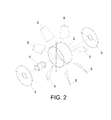
- Figure 2 shows an exploded view of the impeller of figure 1 , clearly showing the core of the impeller composed of an outer enclosure (2), to which two inner discs (3) are welded. These discs provide rigidity to the enclosure, thereby preventing deformations in the same.
- a central stump (4) is welded in these discs (3), which shall be the attachment element between the impeller (1) and the motor.
- the stump (4) is mechanized with the housing required by the shaft of the motor, that is to say, the stump (4) will have a diameter that will depend on the diameter of the shaft of the motor.
- Figure 3 shows an upper view of a particular embodiment of a vane (5) object of the present invention.
- A, B, C, D, E, and F being different angular distances between different points of the impeller.
- these dimensions would be: A: 28.8°, B: 61.2°, C: 30.8°, D: 30.4°, E: 30° and F: 29°. These dimensions are for a specific embodiment of the impeller, and they may vary depending on the current constructive needs.
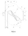
- Figure 4 shows the vane (5) arranged on the outer enclosure (2) of the core of the impeller, K being the inner diameter of the stump (4), H the length of the base of the vane (5) (base being understood as the profile of the vane (5) welded to the enclosure (2)) on the horizontal axis, G the distance from the edge of the enclosure (2) to the end of the base of the vane (5), N the length of the cover of the vane (cover being understood as the intermediate piece of the welding of the upper end of the vane (5)) on the horizontal axis, L the length of the cover of the vane (5) on the vertical axis, J the distance between the center of the vane (5) and the end of the base of the vane on the vertical axis and M the distance between the edge of the enclosure (2) and the end of the cover of the vane (5) on the horizontal axis.
- the vanes (5) are formed by the attachment, by welding, of stamped pieces. Specifically, by means of the welding of a first plate (6), which shall act as the impeller surface, and a second plate (7), which shall act as the impeller surface.
- the stamping of the different pieces of the vane provides the same with its aerodynamic shape.
- an intermediate piece (8) between the upper ends of the first and second plate that is welded in order to close the hollow in the upper part of the vane (5) and provide further strength to the welding is used.
- the use of dies is required, and the forming process of the different pieces can vary depending on the profile used in each vane.
- symmetrical profile vanes the same piece is used regardless of the surface of the vane.
- the surfaces are different, depending on the pressure or suction surface.
- These stamped pieces shall have, in a particular embodiment of the invention, a thickness of 1.5 mm, there being a hollow space between them, after they have been welded, of approximately 7 mm.
- the vane set (15) has a length, in its upper profile, of 11 centimeters and a length of 23 cm. It is more than obvious that a piece with the aforementioned dimensions and with the hollow existing in the interior of the vane achieves important savings in terms of material, and therefore in weight, in addition to supposing important savings in terms of cost.
- the vanes (5) are attached to the core. This attachment to the core is achieved by means of the welding of the vanes (5) to the outer surface of the outer enclosure (2). This placement must be precise and similar in all vanes (5). To achieve the foregoing assembly templates are used, with which the correct positioning of all the vanes (5) is accomplished. In the first place, the vanes (5) are cut along their lower part by means of three-dimensional laser cutting, a cut that depends on the angle that the vanes must have in the impeller to provide the propulsion specified for each fan model, in order for the lower part of the vane to perfectly match the exterior cylindrical enclosure of the core.
- the manufacturing range of these impellers (1) comprises ⁇ 500 mm to ⁇ 1,600 mm of outer measurement.
- the number of vanes (5) and the diameter of the core is determined not only by the outer diameter but by the power for which they are manufactured.
- the preferred manufacturing powers of the impellers are preferably comprised between 7.5 kW and 90 kW, although the method and impeller described herein can lead to greater and lower powers than those comprised in the aforementioned range.
- the spaces among inner elements or hollows can be filled with foam, wool or any other insulating material.
Landscapes
- Engineering & Computer Science (AREA)
- Mechanical Engineering (AREA)
- General Engineering & Computer Science (AREA)
- Chemical & Material Sciences (AREA)
- Combustion & Propulsion (AREA)
- Structures Of Non-Positive Displacement Pumps (AREA)
Applications Claiming Priority (1)
| Application Number | Priority Date | Filing Date | Title |
|---|---|---|---|
| PCT/ES2012/070144 WO2013132113A1 (fr) | 2012-03-07 | 2012-03-07 | Roue de ventilateurs et procédé de fabrication de roues de ventilateurs |
Publications (2)
| Publication Number | Publication Date |
|---|---|
| EP2824331A1 true EP2824331A1 (fr) | 2015-01-14 |
| EP2824331A4 EP2824331A4 (fr) | 2015-08-19 |
Family
ID=49115973
Family Applications (1)
| Application Number | Title | Priority Date | Filing Date |
|---|---|---|---|
| EP12870657.9A Withdrawn EP2824331A4 (fr) | 2012-03-07 | 2012-03-07 | Roue de ventilateurs et procédé de fabrication de roues de ventilateurs |
Country Status (2)
| Country | Link |
|---|---|
| EP (1) | EP2824331A4 (fr) |
| WO (1) | WO2013132113A1 (fr) |
Cited By (2)
| Publication number | Priority date | Publication date | Assignee | Title |
|---|---|---|---|---|
| IT201800004983A1 (it) * | 2018-05-02 | 2019-11-02 | Girante per ventilatori a getto, in particolare per ventilatori per gallerie, e metodo per produrre giranti. | |
| EP4379213A1 (fr) * | 2022-12-02 | 2024-06-05 | Italoiberica Engineering Group Sl | Dispositif de ventilation forcée, en particulier pour tunnels routiers et similaires |
Family Cites Families (12)
| Publication number | Priority date | Publication date | Assignee | Title |
|---|---|---|---|---|
| GB669745A (en) * | 1949-01-13 | 1952-04-09 | Richardsons Westgarth & Co | Improvements in and relating to marine propellers |
| US2865598A (en) * | 1954-03-03 | 1958-12-23 | Merland L Moseson | Air cooled turbine wheel design |
| US4040769A (en) * | 1976-02-20 | 1977-08-09 | Britz Robert N | Fan wheel |
| US4295789A (en) * | 1979-08-09 | 1981-10-20 | Robinson Industries, Inc. | Cover plates for tank heads |
| US5253824A (en) * | 1991-04-16 | 1993-10-19 | General Electric Company | Hollow core airfoil |
| JPH0712097A (ja) * | 1993-06-23 | 1995-01-17 | Hirose Tekkogyo Kk | 軸流扇及びその製造方法 |
| SE519781C2 (sv) * | 2001-08-29 | 2003-04-08 | Volvo Aero Corp | Förfarande för framställning av en stator-eller rotorkomponent |
| CN2527761Y (zh) * | 2001-11-27 | 2002-12-25 | 北京森博苑科技有限公司 | 前向弯掠扭曲板型轴流风机叶轮 |
| GB2451779A (en) * | 2004-09-22 | 2009-02-11 | Rolls Royce Plc | Manufacturing aerofoil with metal foam core |
| TWI378183B (en) * | 2008-03-31 | 2012-12-01 | Delta Electronics Inc | Fan and impeller thereof |
| DE102008058786A1 (de) * | 2008-11-24 | 2010-05-27 | Rolls-Royce Deutschland Ltd & Co Kg | Hybrides Bauteil für ein Gasturbinentriebwerk |
| DE102008058913A1 (de) * | 2008-11-25 | 2010-05-27 | Rolls-Royce Deutschland Ltd & Co Kg | Verfahren zur Herstellung hybrider Bauteile für Fluggasturbinen |
-
2012
- 2012-03-07 WO PCT/ES2012/070144 patent/WO2013132113A1/fr not_active Ceased
- 2012-03-07 EP EP12870657.9A patent/EP2824331A4/fr not_active Withdrawn
Cited By (2)
| Publication number | Priority date | Publication date | Assignee | Title |
|---|---|---|---|---|
| IT201800004983A1 (it) * | 2018-05-02 | 2019-11-02 | Girante per ventilatori a getto, in particolare per ventilatori per gallerie, e metodo per produrre giranti. | |
| EP4379213A1 (fr) * | 2022-12-02 | 2024-06-05 | Italoiberica Engineering Group Sl | Dispositif de ventilation forcée, en particulier pour tunnels routiers et similaires |
Also Published As
| Publication number | Publication date |
|---|---|
| EP2824331A4 (fr) | 2015-08-19 |
| WO2013132113A1 (fr) | 2013-09-12 |
Similar Documents
| Publication | Publication Date | Title |
|---|---|---|
| US11261877B2 (en) | Ceiling fan blade | |
| JP5716951B2 (ja) | 送風ファンおよび送風ファンの製造方法 | |
| CN112443450B (zh) | 用于风力涡轮的转子的毂组件 | |
| CN201865944U (zh) | 散热风扇组合结构 | |
| CN105408636A (zh) | 用于风机组件和风机轮组件的方法 | |
| US20090317256A1 (en) | Rotor hub of a wind energy plant | |
| EP3369937B1 (fr) | Procédé de fabrication d'impulseur | |
| US9200641B2 (en) | Axial fan and a method of manufacturing a blower pipe therefor | |
| EP2824331A1 (fr) | Roue de ventilateurs et procédé de fabrication de roues de ventilateurs | |
| CN102840097B (zh) | 用于与风力涡轮机一起使用的毂组件及其制造方法 | |
| CN102168687B (zh) | 一种轮毂直径为φ762的压气机首级叶片 | |
| CN107404203B (zh) | 一种转子生产方法 | |
| CN102957234A (zh) | 一种冰箱压缩机用电机转子 | |
| WO2015083142A1 (fr) | Éolienne à axe vertical multi-segment | |
| CN107035717A (zh) | 一种水泵叶轮及其制备方法 | |
| CN107524632A (zh) | 榫铆叶轮的生产方法 | |
| JP2014084718A (ja) | 垂直軸形風車 | |
| CN105179308A (zh) | 改进叶片结构的水泵及一种可调整流量和效率的水泵组件 | |
| EP2942484B1 (fr) | Traverses d'élément de pale | |
| CN210525847U (zh) | 一种叶轮模具 | |
| CN111641277B (zh) | 一种汽轮发电机定子压圈 | |
| CN212462904U (zh) | 一种汽轮发电机定子压圈 | |
| CN203056712U (zh) | 一种冰箱压缩机用电机转子 | |
| CN208935028U (zh) | 用于风叶组件的连接组件及具有其的空调器 | |
| CN213540837U (zh) | 一种外转子轴流风机的风叶装配结构 |
Legal Events
| Date | Code | Title | Description |
|---|---|---|---|
| PUAI | Public reference made under article 153(3) epc to a published international application that has entered the european phase |
Free format text: ORIGINAL CODE: 0009012 |
|
| 17P | Request for examination filed |
Effective date: 20140811 |
|
| AK | Designated contracting states |
Kind code of ref document: A1 Designated state(s): AL AT BE BG CH CY CZ DE DK EE ES FI FR GB GR HR HU IE IS IT LI LT LU LV MC MK MT NL NO PL PT RO RS SE SI SK SM TR |
|
| AX | Request for extension of the european patent |
Extension state: BA ME |
|
| DAX | Request for extension of the european patent (deleted) | ||
| RA4 | Supplementary search report drawn up and despatched (corrected) |
Effective date: 20150717 |
|
| RIC1 | Information provided on ipc code assigned before grant |
Ipc: F04D 29/32 20060101ALI20150713BHEP Ipc: F04D 29/38 20060101ALI20150713BHEP Ipc: F01D 5/14 20060101AFI20150713BHEP |
|
| STAA | Information on the status of an ep patent application or granted ep patent |
Free format text: STATUS: THE APPLICATION IS DEEMED TO BE WITHDRAWN |
|
| 18D | Application deemed to be withdrawn |
Effective date: 20160216 |