EP2826524A1 - Appareil de traitement cardiaque destiné à détecter des tachycardies ou fibrillations ventriculaires - Google Patents
Appareil de traitement cardiaque destiné à détecter des tachycardies ou fibrillations ventriculaires Download PDFInfo
- Publication number
- EP2826524A1 EP2826524A1 EP14168458.9A EP14168458A EP2826524A1 EP 2826524 A1 EP2826524 A1 EP 2826524A1 EP 14168458 A EP14168458 A EP 14168458A EP 2826524 A1 EP2826524 A1 EP 2826524A1
- Authority
- EP
- European Patent Office
- Prior art keywords
- ventricular
- electrode
- therapy device
- dislocation
- tachycardia
- Prior art date
- Legal status (The legal status is an assumption and is not a legal conclusion. Google has not performed a legal analysis and makes no representation as to the accuracy of the status listed.)
- Granted
Links
Images



Classifications
-
- A—HUMAN NECESSITIES
- A61—MEDICAL OR VETERINARY SCIENCE; HYGIENE
- A61N—ELECTROTHERAPY; MAGNETOTHERAPY; RADIATION THERAPY; ULTRASOUND THERAPY
- A61N1/00—Electrotherapy; Circuits therefor
- A61N1/18—Applying electric currents by contact electrodes
- A61N1/32—Applying electric currents by contact electrodes alternating or intermittent currents
- A61N1/36—Applying electric currents by contact electrodes alternating or intermittent currents for stimulation
- A61N1/362—Heart stimulators
- A61N1/365—Heart stimulators controlled by a physiological parameter, e.g. heart potential
- A61N1/36592—Heart stimulators controlled by a physiological parameter, e.g. heart potential controlled by the heart rate variability
-
- A—HUMAN NECESSITIES
- A61—MEDICAL OR VETERINARY SCIENCE; HYGIENE
- A61N—ELECTROTHERAPY; MAGNETOTHERAPY; RADIATION THERAPY; ULTRASOUND THERAPY
- A61N1/00—Electrotherapy; Circuits therefor
- A61N1/18—Applying electric currents by contact electrodes
- A61N1/32—Applying electric currents by contact electrodes alternating or intermittent currents
- A61N1/36—Applying electric currents by contact electrodes alternating or intermittent currents for stimulation
- A61N1/362—Heart stimulators
- A61N1/3621—Heart stimulators for treating or preventing abnormally high heart rate
- A61N1/3622—Heart stimulators for treating or preventing abnormally high heart rate comprising two or more electrodes co-operating with different heart regions
-
- A—HUMAN NECESSITIES
- A61—MEDICAL OR VETERINARY SCIENCE; HYGIENE
- A61N—ELECTROTHERAPY; MAGNETOTHERAPY; RADIATION THERAPY; ULTRASOUND THERAPY
- A61N1/00—Electrotherapy; Circuits therefor
- A61N1/18—Applying electric currents by contact electrodes
- A61N1/32—Applying electric currents by contact electrodes alternating or intermittent currents
- A61N1/36—Applying electric currents by contact electrodes alternating or intermittent currents for stimulation
- A61N1/362—Heart stimulators
- A61N1/37—Monitoring; Protecting
-
- A—HUMAN NECESSITIES
- A61—MEDICAL OR VETERINARY SCIENCE; HYGIENE
- A61N—ELECTROTHERAPY; MAGNETOTHERAPY; RADIATION THERAPY; ULTRASOUND THERAPY
- A61N1/00—Electrotherapy; Circuits therefor
- A61N1/18—Applying electric currents by contact electrodes
- A61N1/32—Applying electric currents by contact electrodes alternating or intermittent currents
- A61N1/38—Applying electric currents by contact electrodes alternating or intermittent currents for producing shock effects
- A61N1/39—Heart defibrillators
- A61N1/3956—Implantable devices for applying electric shocks to the heart, e.g. for cardioversion
- A61N1/3962—Implantable devices for applying electric shocks to the heart, e.g. for cardioversion in combination with another heart therapy
- A61N1/39622—Pacing therapy
-
- A—HUMAN NECESSITIES
- A61—MEDICAL OR VETERINARY SCIENCE; HYGIENE
- A61N—ELECTROTHERAPY; MAGNETOTHERAPY; RADIATION THERAPY; ULTRASOUND THERAPY
- A61N1/00—Electrotherapy; Circuits therefor
- A61N1/18—Applying electric currents by contact electrodes
- A61N1/32—Applying electric currents by contact electrodes alternating or intermittent currents
- A61N1/38—Applying electric currents by contact electrodes alternating or intermittent currents for producing shock effects
- A61N1/39—Heart defibrillators
- A61N1/3987—Heart defibrillators characterised by the timing or triggering of the shock
-
- A—HUMAN NECESSITIES
- A61—MEDICAL OR VETERINARY SCIENCE; HYGIENE
- A61N—ELECTROTHERAPY; MAGNETOTHERAPY; RADIATION THERAPY; ULTRASOUND THERAPY
- A61N1/00—Electrotherapy; Circuits therefor
- A61N1/18—Applying electric currents by contact electrodes
- A61N1/32—Applying electric currents by contact electrodes alternating or intermittent currents
- A61N1/36—Applying electric currents by contact electrodes alternating or intermittent currents for stimulation
- A61N1/362—Heart stimulators
- A61N1/365—Heart stimulators controlled by a physiological parameter, e.g. heart potential
- A61N1/368—Heart stimulators controlled by a physiological parameter, e.g. heart potential comprising more than one electrode co-operating with different heart regions
- A61N1/3684—Heart stimulators controlled by a physiological parameter, e.g. heart potential comprising more than one electrode co-operating with different heart regions for stimulating the heart at multiple sites of the ventricle or the atrium
-
- A—HUMAN NECESSITIES
- A61—MEDICAL OR VETERINARY SCIENCE; HYGIENE
- A61N—ELECTROTHERAPY; MAGNETOTHERAPY; RADIATION THERAPY; ULTRASOUND THERAPY
- A61N1/00—Electrotherapy; Circuits therefor
- A61N1/18—Applying electric currents by contact electrodes
- A61N1/32—Applying electric currents by contact electrodes alternating or intermittent currents
- A61N1/36—Applying electric currents by contact electrodes alternating or intermittent currents for stimulation
- A61N1/362—Heart stimulators
- A61N1/365—Heart stimulators controlled by a physiological parameter, e.g. heart potential
- A61N1/368—Heart stimulators controlled by a physiological parameter, e.g. heart potential comprising more than one electrode co-operating with different heart regions
- A61N1/3684—Heart stimulators controlled by a physiological parameter, e.g. heart potential comprising more than one electrode co-operating with different heart regions for stimulating the heart at multiple sites of the ventricle or the atrium
- A61N1/36843—Bi-ventricular stimulation
Definitions
- the tachycardia detection unit thus allows a biventricular detection of tachyarrhythmias such as ventricular tacchycardia (VT) or fibrillation (VF).
- VT ventricular tacchycardia
- VF fibrillation
- the therapy device controller can then trigger adequate therapies.
- a system known as the S-ICD system uses a far-field channel for VT / VF detection.
- a particular type of tachyarrhythmia is "dissimilar" ventricular tachycardia, where the right ventricle (RV) and the left ventricle (LV) have different (beat or contraction) frequencies.
- the inventors have recognized that current biventricular cardiac therapy devices are deficient in dissimilar ventricular tachycardias.
- the aim of the invention is to provide a biventricular cardiac therapy device which can adequately respond to dissimilar ventricular tachycardias.
- this object is achieved by an implantable biventricular cardiac therapy device of the type mentioned, in which the tachycardia detection unit is designed to simultaneously evaluate the heart rate at the right ventricular and at the left ventricular electrode for the detection of ventricular tachycardias.
- the therapy device controller has a dislocation recognition unit, which is likewise at least indirectly connected or connectable to a right ventricular sense electrode and a left ventricular sense electrode in such a way that the dislocation recognition unit is supplied with signals representing a time characteristic of electrical potentials in the heart or signals derived therefrom become.
- the dislocation recognition unit is designed to simultaneously evaluate the heart rate at the right ventricular and the left ventricular electrode and to signal a right or left ventricular dislocation and to generate a corresponding dislocation signal whenever the dislocation recognition unit detects a sudden increase in the frequency of the right. or left ventricular electrode perceives without a significant change in rhythm at the left or the right ventricular electrode is detected within a predetermined and / or adjustable time window.
- the therapy device controller is designed to ignore the rhythm information of the affected electrode for tachycardia detection in the event of a signaled dislocation of the right ventricular or the left ventricular electrode.
- cardiac therapy device makes it possible to deliver adequate therapy in good time in patients with differently rapid ventricular tachycardias in both ventricles without inadequate therapy being given in the event of an electrode dislocation.
- An advantage of the cardiac therapy device according to the invention is thus also the avoidance of misdetections in a dislocated probe and simultaneous atrial fibrillation.
- the invention includes the insight that previous marketable ICD systems operate exclusively with a right ventricular VT / VF recognition channel.
- the left ventricular sensing signals are used here only to inhibit unnecessary LV stimulation and to record an intracardiac electrocardiogram (IEGM), but not VT / VF detection.
- IEGM intracardiac electrocardiogram
- the cardiac therapy device results in operation an implantable defibrillator with at least one right ventricular electrode and at least one left ventricular (preferably coronary sinus) electrode, each operatively connected to a tachycardia detection unit, wherein the tachycardia detection unit is designed so that it is used for the detection of ventricular tachycardia simultaneously assessed the heart rate at the right ventricular and left ventricular electrodes.
- a respective sense electrode pole for bipolar or unipolar perception of electrical potential profiles in the myocardium of the respective heart chamber is here meant, which is part of a corresponding electrode line and is connected via this to the cardiac therapy device.
- the additional dislocation recognition unit allows detection of a possible dislocation of one of the ventricular electrodes and is designed to simultaneously evaluate the heart rate at the right ventricular and left ventricular electrodes and to signal a right or left ventricular dislocation whenever a sudden increase in the frequency at the Right and left ventricular electrode is perceived without a significant change in rhythm at the left or right ventricular electrode is detected promptly, so signaled at one Dislocation of one of the ventricular electrodes, the rhythm information of the affected electrode for tachycardia detection can be ignored.
- the tachycardia detection unit is designed to ignore a signal for tachycardia detection originating from a particular electrode in question on a dislocation signal of the dislocation recognition unit. This can also be effected by not even supplying the tachycardia detection unit with a signal originating from an electrode which has been detected as dislocated.
- the cardiac therapy device preferably has an additional atrial electrode, wherein the cardiac therapy device is designed to perform the above-described dislocation test by the dislocation recognition unit only when atrial fibrillation (atrial fibrillation, AF) is perceived at the atrial electrode.
- atrial fibrillation atrial fibrillation, AF
- an AF detection unit may be provided for detecting atrial fibrillation which, in the event of detected atrial fibrillation, outputs an AF signal which i.a. deactivating the dislocation detection unit causes.
- the dislocation recognition unit is preferably designed to use the following criteria or their combination in addition to left ventricular dislocation recognition: a maximum allowed premature left ventricular contraction before a right ventricular contraction, stability of the A-RV transit time, i. the transition time from the atrium to the right ventricle, a frequency comparison between the atrium and left ventricle, the left ventricular stimulation threshold, the morphology of left ventricular R-waves before each provisionally recorded and confirmed tachycardia, amplitudes, impedances, pacing thresholds.
- the cardiac therapy device is a three-chamber device which is connected to or connected to a right atrial electrode, right ventricular electrode and a left ventricular electrode.
- the tachycardia detection unit is then preferably arranged to substitute, in addition to or in addition to known two-chamber discrimination algorithms (involving the right atrium and the right ventricle), a 3-chamber discrimination algorithm that has been extended in which the classification of the origin of a tachycardia in principle, the interval information of the left ventricle are included and also the A-LV conduction times from the atrium to the left ventricle are taken into account, for example, as in the below in FIG. 7 illustrated embodiment is illustrated.
- the tachycardia detection unit is also adapted to provide a per se known onset criterion (sudden onset, ie, a sudden increase in heart rate within one or a very small number of cardiac cycles) for discriminating between a physiological rate increase (resulting in a Sinus tachycardia) and a sudden onset of ventricular tachycardia is augmented by left ventricular rhythm assessment, and only then is sinus tachycardia signaled (by outputting a corresponding tachyarrhythmia signal) when there is no sudden increase in frequency in the right ventricle and no sudden increase in frequency in the left ventricle takes place and / or the interventricular conduction times remain unchanged, taking into account a tolerance.
- a per se known onset criterion Sudden onset, ie, a sudden increase in heart rate within one or a very small number of cardiac cycles
- the tachycardia detection unit is also adapted to apply a per se known ventricular stability criterion for distinguishing between a stable monomorphic ventricular tachycardia and a relayed atrial fibrillation in such expanded form that ventricular tachycardia (VT) is detected only when the ventricular tachycardia Rhythm is classified as stable in both ventricles.
- VT ventricular tachycardia
- the cardiac therapy device is preferably designed to control the timing by the therapy device control of the pacemaker and thus, in particular, the blanking times required for the tachycardia detection, as in FIG US 2011/0082512 then automatically switch to the left ventricular side (ie, to control times based on sensed left ventricular events) if the left ventricular signals for tachycardia detection are classified as appropriate, ie no dislocation is detected.
- a further advantageous embodiment of such a therapy device is on US 2011/0082512 respectively.
- EP 2 308 558 referred to, the disclosure of which is included in this application.
- Austex time ie times when a respective sensing unit can either not perceive cardiac events or times at which sensed cardiac events for tachycardia detection are ignored, are generally known to those skilled in the art.
- the biventricular detection tachycardia detection unit has separate detection counters for the right ventricular and left ventricular signals and is designed such that the reaching of a predetermined count of one of the two counters triggers a corresponding detection and thus a corresponding tachyarrhythmia signal.
- the biventricular detection tachycardia detection unit has common detection counters for the right ventricular and left ventricular signals, these always being determined by the faster ventricular side, given a different interval between right ventricular and left ventricular signals.
- a termination criterion used by the therapy device controller to terminate anti-tachycardia pacing it is preferred that the therapy device controller achieve a termination criterion that is deemed to be met only if measured interval durations in both the right ventricle and in the left ventricle are greater than a predetermined interval limit for the termination.
- a therapy device control which is designed in such a way that the termination criterion is satisfied even if the measured interval duration is greater than a predetermined interval limit for the termination only in the right ventricle.
- the cardiac therapy device also realizes a right- and left-ventricular antisense detection, eg by means of a plausibility check on right and left ventricular and optionally atrial number of intervals, and is designed to switch over to a right ventricular or left ventricular detection whenever one of the Ventricular electrodes have a significant undersensing, ie, when one of the ventricular electrodes due to partially unrecognized cardiac events detected significantly fewer heart cycles than, the other or other electrodes.
- a right- and left-ventricular antisense detection eg by means of a plausibility check on right and left ventricular and optionally atrial number of intervals, and is designed to switch over to a right ventricular or left ventricular detection whenever one of the Ventricular electrodes have a significant undersensing, ie, when one of the ventricular electrodes due to partially unrecognized cardiac events detected significantly fewer heart cycles than, the other or other electrodes.
- the tachycardia detection unit is designed such that they are evaluated between a purely right ventricular tachycardia detection, in which only from a right ventricular electrode and optionally additionally derived from an atrial electrode signals for tachycardia detection, and a biventricular tachycardia detection, in which also from a Left ventricular lead-derived signals for tachycardia detection are switchable.
- a purely right ventricular detection always first takes place until a stable electrode position in the left ventricle has been automatically detected by the cardiac therapy device and then the biventricular detection is automatically activated.
- the cardiac therapy device is designed for such an automatic switching.
- the cardiac therapy device or its therapy device controller is preferably designed such that it performs an additional dislocation test of the left ventricular electrode after each delivery of a defibrillation shock in an aforementioned manner.
- the dislocation detection unit is preferably designed to detect only dislocation of a left ventricular electrode, i. the dislocation recognition performed by the dislocation recognition unit relates only to a respective left ventricular coronary sinus electrode, since the probability of a dislocation is greater here.
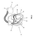
- FIG. 2 shows a biventricular pacemaker / defibrillator (ICD or CRT-D) with a right ventricular defibrillation shock coil as an implantable cardiac therapy device 10.
- This biventricular pacemaker is via electrode leads 16 and 30 with pacing and sensing electrodes 18 and 20 and 32 and 34 in the right and left ventricles connected to a heart and can thus deliver stimulation pulses to the heart and record electrical potentials from the heart.
- the electrode line 16 is a right-ventricular electrode lead and has at its distal end a right-ventricular tip electrode pole RV tip 18 and in the immediate vicinity a right-ventricular ring electrode pole RV ring 20. Both electrode poles are arranged in the apex of the right ventricle of the heart.
- the electrode line 30 is a left ventricular electrode lead and has at the distal end a bipolar pacing and sensing electrode with a distal tip electrode pole LV tip 34 and in the vicinity thereof a left ventricular ring electrode pole LV ring 32.
- the left ventricular electrode lead 30 is guided from the right atrium 26 of the heart 12 via the coronary sinus into a lateral vein branching from the coronary sinus and is therefore also referred to as a coronary sinus lead or a CS lead.
- the right ventricular electrode lead 16 also carries a right-ventricular shock coil RV shock 38 as a large electrode pole for the delivery of defibrillation shocks.
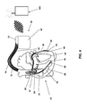
- the control unit 54 includes a tachycardia detection unit 90 and a dislocation detection unit 92.
- the right ventricular pacing unit 56 is designed to generate a right ventricular pacing pulse in response to a drive signal from the control unit 54 and to dispense it via the terminals for the right ventricular ring electrode pole and the right ventricular tip electrode pole.
- the housing 42 of the heart stimulator 10 forms a neutral electrode and the right ventricular stimulation unit 56 is connected to the terminal for the right ventricular tip electrode RV tip and the housing 42 as another electrode for delivering a stimulation pulse.
- a right ventricular stimulation pulse differs from a defibrillation shock in that the stimulation pulse has a much lower pulse strength so that it does not excite the full heart tissue (myocardium) of a ventricle like a defibrillation shock at one go, but only the heart muscle cells in the immediate vicinity of the right ventricular tip electrode pole 18 This excitement then spreads natural conduction across the entire ventricle and thus provides for a stimulated contraction of the ventricle.
- the largest amplitude of the signal in the form of the so-called R wave is indicative of a natural contraction of the right ventricle, which can be detected by threshold comparison.
- the right ventricular sensing unit 58 then outputs an appropriate natural right ventricular contraction output signal (e.g., a marker signal) to the control unit 54 and its tachycardia detection unit 90 and dislocation detection unit 92.
- connection for the left ventricular tip electrode pole LV tip and the connection for the left ventricular ring electrode pole LV ring are also connected to the left ventricular stimulation unit 64 and a left ventricular sensing unit 66.
- the left ventricular pacing unit 64 and the left ventricular sensing unit 66 are also connected to the control unit 54. Both function similarly to the previously described stimulation units 56 and 60 and sensing units 58 and 62.
- an activity sensor 72 is connected to the control unit 54.
- the activity sensor 72 is configured to detect a signal dependent on the physical activity of a patient, for example a movement signal, and a corresponding physical activity of the patient Output patient-indicating signal to the control unit 54. This allows the controller 54 to adjust the timing of the stimulation pulses to the needs of the patient (hemodynamic needs).
- the heart stimulator 10 comprises a memory unit 80, which is connected to the control unit 54 and allows signals generated or evaluated by the control unit 54 to be stored.
- the memory unit 80 allows control programs for the control unit 54 to be stored in a variable form.
- the control unit 54 is connected to a timer 84.
- the heart stimulator 10 has at least one bi-directional telemetry interface 84 to transmit stored data from the electronic implant to an external device 100, and conversely, to receive programming settings and therapy commands from that external device 100 as well.
- the electrode line 14 is an atrial electrode line has at the distal end a bipolar stimulation and sensing electrode formed by a Tip electrode pole RA tip 22 and a ring electrode pole RA ring 24 implanted in the right atrium 26.
- the left ventricular lead 30 additionally carries a left ventricular shock coil 36 for delivery of defibrillation shocks to the left ventricle.
- This shock coil 36 is arranged so that it extends from the left ventricle 44 up to the left atrium 46.
- Another electrode for the shock delivery represents the electrically active housing 42 of the implant 10.
- the heart tachycardiac ventricular arrhythmias are classified primarily via the perceived cardiac actions of the right ventricular and the left ventricular electrode leads simultaneously, with the faster arrhythmia primarily determining the choice of therapy.
- a check is also made for a possible dislocation of one of the ventricular electrodes in order to prevent inadequate therapy delivery. If such a dislocation is detected, the affected electrode is no longer used for tachycardia detection.
- the dislocation recognition provided for the biventricular detection and performed by the dislocation recognition unit 92 is illustrated in a flow chart using the example of an LV dislocation recognition, ie a detection of a dislocation of the left ventricular electrode.
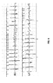
- the left ventricular lead 30 (and thus the left ventricular lead, including the left ventricular tip electrode LV tip 34 and the left ventricular ring electrode LV ring 32) may slip within the coronary vein such that their lead poles 32 and 34 are in the area of the atrium, it is not excluded that an existing atrial tachycardia is falsely perceived as a left ventricular tachycardia and inadequate therapy in biventricular detection (see FIG. 6 ) is triggered.
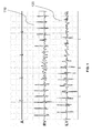
- FIG. 6 is shown for a biventricular detection suitable counter logic and the example of illustration 1 illustrated as a marker chain.
- the detection by the tachycardia detection unit takes place here via only one detection counter, which is incremented whenever an interval falls below the programmed tachycardia zone limit.
- right and left ventricular perceived intervals are permitted as intervals, whereby a right ventricular interval is only allowed for the count if this is shorter than or equal to the previous left ventricular interval.
- a left ventricular interval is only allowed to be counted if it is shorter than the preceding right ventricular interval.
- interval markers allowed for tachycardia evaluation are indicated by the following symbol:
- FIG. 7 a possible variant of a 3-chamber discrimination algorithm with biventricular detection is shown by way of example. This demonstrates only one of the possible implementation variants, since the biventricular discrimination can in principle be integrated into all existing discrimination algorithms and in any case an improvement in the sensitivity and specificity of the VT / SVT discrimination (ie the distinction of original ventricular tachycardias (VT) of supraventricular tachycardias ( SVT)).
- VT ventricular tachycardias
- SVT supraventricular tachycardias
Landscapes
- Health & Medical Sciences (AREA)
- Cardiology (AREA)
- Heart & Thoracic Surgery (AREA)
- Life Sciences & Earth Sciences (AREA)
- Radiology & Medical Imaging (AREA)
- Engineering & Computer Science (AREA)
- Biomedical Technology (AREA)
- Nuclear Medicine, Radiotherapy & Molecular Imaging (AREA)
- Animal Behavior & Ethology (AREA)
- General Health & Medical Sciences (AREA)
- Public Health (AREA)
- Veterinary Medicine (AREA)
- Physiology (AREA)
- Biophysics (AREA)
- Electrotherapy Devices (AREA)
Applications Claiming Priority (2)
| Application Number | Priority Date | Filing Date | Title |
|---|---|---|---|
| US201361847093P | 2013-07-17 | 2013-07-17 | |
| US201361865625P | 2013-08-14 | 2013-08-14 |
Publications (2)
| Publication Number | Publication Date |
|---|---|
| EP2826524A1 true EP2826524A1 (fr) | 2015-01-21 |
| EP2826524B1 EP2826524B1 (fr) | 2015-07-22 |
Family
ID=50729380
Family Applications (2)
| Application Number | Title | Priority Date | Filing Date |
|---|---|---|---|
| EP14168457.1A Not-in-force EP2826523B1 (fr) | 2013-07-17 | 2014-05-15 | Appareil thérapeutique cardiaque implantable |
| EP14168458.9A Active EP2826524B1 (fr) | 2013-07-17 | 2014-05-15 | Appareil de traitement cardiaque destiné à détecter des tachycardies ou fibrillations ventriculaires |
Family Applications Before (1)
| Application Number | Title | Priority Date | Filing Date |
|---|---|---|---|
| EP14168457.1A Not-in-force EP2826523B1 (fr) | 2013-07-17 | 2014-05-15 | Appareil thérapeutique cardiaque implantable |
Country Status (2)
| Country | Link |
|---|---|
| US (2) | US9314643B2 (fr) |
| EP (2) | EP2826523B1 (fr) |
Families Citing this family (1)
| Publication number | Priority date | Publication date | Assignee | Title |
|---|---|---|---|---|
| DE102019110284A1 (de) * | 2019-04-18 | 2020-10-22 | Biotronik Se & Co. Kg | Implantierbare Anordnung zur Stimulation eines menschlichen oder tierischen Herzens |
Citations (4)
| Publication number | Priority date | Publication date | Assignee | Title |
|---|---|---|---|---|
| US20070255327A1 (en) * | 2006-04-26 | 2007-11-01 | Cho Yong K | Implantable Medical Device with Electromechanical Delay Measurement for Lead Position and Ventricular |
| US20090125077A1 (en) * | 2007-11-14 | 2009-05-14 | Thomas Doerr | Biventricular cardiac stimulator |
| US20110082512A1 (en) | 2009-10-07 | 2011-04-07 | Biotronik Crm Patent Ag | Biventricular cardiac stimulator |
| US20130030314A1 (en) * | 2011-07-29 | 2013-01-31 | Keel Allen J | Devices, systems and methods to perform arrhythmia discrimination based on the atrial and ventricular activation times |
Family Cites Families (5)
| Publication number | Priority date | Publication date | Assignee | Title |
|---|---|---|---|---|
| US7664550B2 (en) * | 2004-11-30 | 2010-02-16 | Medtronic, Inc. | Method and apparatus for detecting left ventricular lead displacement based upon EGM change |
| DE102006023517A1 (de) | 2006-05-19 | 2007-11-22 | Biotronik Crm Patent Ag | Herzstimulator |
| US7672723B2 (en) * | 2007-04-30 | 2010-03-02 | Biotronik Crm Patent Ag | Implantable medical device for biventricular stimulation |
| DE102008020022A1 (de) * | 2008-04-22 | 2009-10-29 | Biotronik Crm Patent Ag | Antitachykarder Herzstimulator |
| DE102008002293A1 (de) * | 2008-06-09 | 2009-12-10 | Biotronik Crm Patent Ag | Antitachykarder Herzstimulator |
-
2014
- 2014-05-15 EP EP14168457.1A patent/EP2826523B1/fr not_active Not-in-force
- 2014-05-15 EP EP14168458.9A patent/EP2826524B1/fr active Active
- 2014-07-03 US US14/324,015 patent/US9314643B2/en active Active
- 2014-07-03 US US14/324,025 patent/US9364681B2/en not_active Expired - Fee Related
Patent Citations (5)
| Publication number | Priority date | Publication date | Assignee | Title |
|---|---|---|---|---|
| US20070255327A1 (en) * | 2006-04-26 | 2007-11-01 | Cho Yong K | Implantable Medical Device with Electromechanical Delay Measurement for Lead Position and Ventricular |
| US20090125077A1 (en) * | 2007-11-14 | 2009-05-14 | Thomas Doerr | Biventricular cardiac stimulator |
| US20110082512A1 (en) | 2009-10-07 | 2011-04-07 | Biotronik Crm Patent Ag | Biventricular cardiac stimulator |
| EP2308558A1 (fr) | 2009-10-07 | 2011-04-13 | Biotronik CRM Patent AG | Stimulateur cardiaque bi-ventriculaire |
| US20130030314A1 (en) * | 2011-07-29 | 2013-01-31 | Keel Allen J | Devices, systems and methods to perform arrhythmia discrimination based on the atrial and ventricular activation times |
Also Published As
| Publication number | Publication date |
|---|---|
| US9314643B2 (en) | 2016-04-19 |
| US20150025593A1 (en) | 2015-01-22 |
| US20150025592A1 (en) | 2015-01-22 |
| EP2826523A1 (fr) | 2015-01-21 |
| EP2826524B1 (fr) | 2015-07-22 |
| US9364681B2 (en) | 2016-06-14 |
| EP2826523B1 (fr) | 2015-08-19 |
Similar Documents
| Publication | Publication Date | Title |
|---|---|---|
| EP2060299B1 (fr) | Stimulateur cardiaque bi-ventriculaire | |
| DE60222071T2 (de) | Implantierbares Herzschrittmachersystem mit Kalibrierung für automatische Erregungsbestätigung | |
| EP2353644B1 (fr) | Cardioverteur/défibrillateur et dispositif de traitement de signal pour la classification de signaux intra-cardiaux | |
| DE60020514T2 (de) | Verfahren zur Unterscheidung von im Herzen erfassten elektrischen Ereignissen und entsprechendes System | |
| EP2135640A1 (fr) | Dispositif d'électrothérapie destiné au traitement de défaillances du rythme tachycarde d'un cýur | |
| EP3025759A1 (fr) | Appareil implantable actif adapté pour une utilisation avec irm | |
| EP2676697B1 (fr) | Capteur de dislocation | |
| EP2111892B1 (fr) | Stimulateur cardiaque contre la tachychardie | |
| EP2181648B1 (fr) | Stimulateur cardiaque à une chambre | |
| EP3025757B1 (fr) | Appareil actif implantable pour mrt | |
| EP1302158B1 (fr) | Appareil de prédiction de tachyarythmie | |
| EP1774988A2 (fr) | Dispositif implantable pour la détermination des vecteurs cardiaques | |
| EP2135641A1 (fr) | Stimulateur cardiaque contre la tachycardie | |
| EP2140910B1 (fr) | Stimulateur cardiaque destiné au traitement des rythmes tachycardiques | |
| EP2826524B1 (fr) | Appareil de traitement cardiaque destiné à détecter des tachycardies ou fibrillations ventriculaires | |
| EP2111893A1 (fr) | Stimulateur cardiaque ventriculaire | |
| EP2422843B1 (fr) | Appareil de thérapie électronique implantable | |
| EP2111894B1 (fr) | Stimulateur cardiaque doté d'un contrôle de la réussite de la stimulation | |
| EP2184009A2 (fr) | Stimulateur cardiaque à une chambre | |
| EP2308558B1 (fr) | Stimulateur cardiaque bi-ventriculaire | |
| EP2510975A1 (fr) | Stimulateur cardiaque | |
| EP2075033B1 (fr) | Stimulateur cardiaque biventriculaire | |
| EP2174688B1 (fr) | Dispositif pour traitement des signaux du coeur | |
| EP1512431A1 (fr) | Stimulateur électrique | |
| EP1578491B1 (fr) | Stimulateur cardiaque implantable |
Legal Events
| Date | Code | Title | Description |
|---|---|---|---|
| 17P | Request for examination filed |
Effective date: 20140515 |
|
| AK | Designated contracting states |
Kind code of ref document: A1 Designated state(s): AL AT BE BG CH CY CZ DE DK EE ES FI FR GB GR HR HU IE IS IT LI LT LU LV MC MK MT NL NO PL PT RO RS SE SI SK SM TR |
|
| AX | Request for extension of the european patent |
Extension state: BA ME |
|
| PUAI | Public reference made under article 153(3) epc to a published international application that has entered the european phase |
Free format text: ORIGINAL CODE: 0009012 |
|
| R17P | Request for examination filed (corrected) |
Effective date: 20150310 |
|
| RBV | Designated contracting states (corrected) |
Designated state(s): AL AT BE BG CH CY CZ DE DK EE ES FI FR GB GR HR HU IE IS IT LI LT LU LV MC MK MT NL NO PL PT RO RS SE SI SK SM TR |
|
| GRAP | Despatch of communication of intention to grant a patent |
Free format text: ORIGINAL CODE: EPIDOSNIGR1 |
|
| INTG | Intention to grant announced |
Effective date: 20150506 |
|
| GRAS | Grant fee paid |
Free format text: ORIGINAL CODE: EPIDOSNIGR3 |
|
| GRAA | (expected) grant |
Free format text: ORIGINAL CODE: 0009210 |
|
| AK | Designated contracting states |
Kind code of ref document: B1 Designated state(s): AL AT BE BG CH CY CZ DE DK EE ES FI FR GB GR HR HU IE IS IT LI LT LU LV MC MK MT NL NO PL PT RO RS SE SI SK SM TR |
|
| REG | Reference to a national code |
Ref country code: GB Ref legal event code: FG4D Free format text: NOT ENGLISH |
|
| REG | Reference to a national code |
Ref country code: CH Ref legal event code: EP |
|
| REG | Reference to a national code |
Ref country code: IE Ref legal event code: FG4D Free format text: LANGUAGE OF EP DOCUMENT: GERMAN |
|
| REG | Reference to a national code |
Ref country code: AT Ref legal event code: REF Ref document number: 737551 Country of ref document: AT Kind code of ref document: T Effective date: 20150815 |
|
| REG | Reference to a national code |
Ref country code: DE Ref legal event code: R096 Ref document number: 502014000053 Country of ref document: DE |
|
| REG | Reference to a national code |
Ref country code: LT Ref legal event code: MG4D |
|
| REG | Reference to a national code |
Ref country code: NL Ref legal event code: MP Effective date: 20150722 |
|
| PG25 | Lapsed in a contracting state [announced via postgrant information from national office to epo] |
Ref country code: FI Free format text: LAPSE BECAUSE OF FAILURE TO SUBMIT A TRANSLATION OF THE DESCRIPTION OR TO PAY THE FEE WITHIN THE PRESCRIBED TIME-LIMIT Effective date: 20150722 Ref country code: GR Free format text: LAPSE BECAUSE OF FAILURE TO SUBMIT A TRANSLATION OF THE DESCRIPTION OR TO PAY THE FEE WITHIN THE PRESCRIBED TIME-LIMIT Effective date: 20151023 Ref country code: LT Free format text: LAPSE BECAUSE OF FAILURE TO SUBMIT A TRANSLATION OF THE DESCRIPTION OR TO PAY THE FEE WITHIN THE PRESCRIBED TIME-LIMIT Effective date: 20150722 Ref country code: NO Free format text: LAPSE BECAUSE OF FAILURE TO SUBMIT A TRANSLATION OF THE DESCRIPTION OR TO PAY THE FEE WITHIN THE PRESCRIBED TIME-LIMIT Effective date: 20151022 Ref country code: LV Free format text: LAPSE BECAUSE OF FAILURE TO SUBMIT A TRANSLATION OF THE DESCRIPTION OR TO PAY THE FEE WITHIN THE PRESCRIBED TIME-LIMIT Effective date: 20150722 |
|
| PG25 | Lapsed in a contracting state [announced via postgrant information from national office to epo] |
Ref country code: PT Free format text: LAPSE BECAUSE OF FAILURE TO SUBMIT A TRANSLATION OF THE DESCRIPTION OR TO PAY THE FEE WITHIN THE PRESCRIBED TIME-LIMIT Effective date: 20151123 Ref country code: SE Free format text: LAPSE BECAUSE OF FAILURE TO SUBMIT A TRANSLATION OF THE DESCRIPTION OR TO PAY THE FEE WITHIN THE PRESCRIBED TIME-LIMIT Effective date: 20150722 Ref country code: ES Free format text: LAPSE BECAUSE OF FAILURE TO SUBMIT A TRANSLATION OF THE DESCRIPTION OR TO PAY THE FEE WITHIN THE PRESCRIBED TIME-LIMIT Effective date: 20150722 Ref country code: RS Free format text: LAPSE BECAUSE OF FAILURE TO SUBMIT A TRANSLATION OF THE DESCRIPTION OR TO PAY THE FEE WITHIN THE PRESCRIBED TIME-LIMIT Effective date: 20150722 Ref country code: HR Free format text: LAPSE BECAUSE OF FAILURE TO SUBMIT A TRANSLATION OF THE DESCRIPTION OR TO PAY THE FEE WITHIN THE PRESCRIBED TIME-LIMIT Effective date: 20150722 Ref country code: IS Free format text: LAPSE BECAUSE OF FAILURE TO SUBMIT A TRANSLATION OF THE DESCRIPTION OR TO PAY THE FEE WITHIN THE PRESCRIBED TIME-LIMIT Effective date: 20151122 Ref country code: PL Free format text: LAPSE BECAUSE OF FAILURE TO SUBMIT A TRANSLATION OF THE DESCRIPTION OR TO PAY THE FEE WITHIN THE PRESCRIBED TIME-LIMIT Effective date: 20150722 |
|
| REG | Reference to a national code |
Ref country code: DE Ref legal event code: R097 Ref document number: 502014000053 Country of ref document: DE |
|
| PG25 | Lapsed in a contracting state [announced via postgrant information from national office to epo] |
Ref country code: SK Free format text: LAPSE BECAUSE OF FAILURE TO SUBMIT A TRANSLATION OF THE DESCRIPTION OR TO PAY THE FEE WITHIN THE PRESCRIBED TIME-LIMIT Effective date: 20150722 Ref country code: DK Free format text: LAPSE BECAUSE OF FAILURE TO SUBMIT A TRANSLATION OF THE DESCRIPTION OR TO PAY THE FEE WITHIN THE PRESCRIBED TIME-LIMIT Effective date: 20150722 Ref country code: IT Free format text: LAPSE BECAUSE OF FAILURE TO SUBMIT A TRANSLATION OF THE DESCRIPTION OR TO PAY THE FEE WITHIN THE PRESCRIBED TIME-LIMIT Effective date: 20150722 Ref country code: CZ Free format text: LAPSE BECAUSE OF FAILURE TO SUBMIT A TRANSLATION OF THE DESCRIPTION OR TO PAY THE FEE WITHIN THE PRESCRIBED TIME-LIMIT Effective date: 20150722 Ref country code: EE Free format text: LAPSE BECAUSE OF FAILURE TO SUBMIT A TRANSLATION OF THE DESCRIPTION OR TO PAY THE FEE WITHIN THE PRESCRIBED TIME-LIMIT Effective date: 20150722 |
|
| PLBE | No opposition filed within time limit |
Free format text: ORIGINAL CODE: 0009261 |
|
| STAA | Information on the status of an ep patent application or granted ep patent |
Free format text: STATUS: NO OPPOSITION FILED WITHIN TIME LIMIT |
|
| PG25 | Lapsed in a contracting state [announced via postgrant information from national office to epo] |
Ref country code: RO Free format text: LAPSE BECAUSE OF FAILURE TO SUBMIT A TRANSLATION OF THE DESCRIPTION OR TO PAY THE FEE WITHIN THE PRESCRIBED TIME-LIMIT Effective date: 20150722 |
|
| 26N | No opposition filed |
Effective date: 20160425 |
|
| PG25 | Lapsed in a contracting state [announced via postgrant information from national office to epo] |
Ref country code: BE Free format text: LAPSE BECAUSE OF NON-PAYMENT OF DUE FEES Effective date: 20160531 Ref country code: SI Free format text: LAPSE BECAUSE OF FAILURE TO SUBMIT A TRANSLATION OF THE DESCRIPTION OR TO PAY THE FEE WITHIN THE PRESCRIBED TIME-LIMIT Effective date: 20150722 |
|
| PG25 | Lapsed in a contracting state [announced via postgrant information from national office to epo] |
Ref country code: LU Free format text: LAPSE BECAUSE OF FAILURE TO SUBMIT A TRANSLATION OF THE DESCRIPTION OR TO PAY THE FEE WITHIN THE PRESCRIBED TIME-LIMIT Effective date: 20160515 |
|
| REG | Reference to a national code |
Ref country code: FR Ref legal event code: ST Effective date: 20170131 |
|
| PG25 | Lapsed in a contracting state [announced via postgrant information from national office to epo] |
Ref country code: FR Free format text: LAPSE BECAUSE OF NON-PAYMENT OF DUE FEES Effective date: 20160531 |
|
| PG25 | Lapsed in a contracting state [announced via postgrant information from national office to epo] |
Ref country code: NL Free format text: LAPSE BECAUSE OF FAILURE TO SUBMIT A TRANSLATION OF THE DESCRIPTION OR TO PAY THE FEE WITHIN THE PRESCRIBED TIME-LIMIT Effective date: 20150722 |
|
| PG25 | Lapsed in a contracting state [announced via postgrant information from national office to epo] |
Ref country code: HU Free format text: LAPSE BECAUSE OF FAILURE TO SUBMIT A TRANSLATION OF THE DESCRIPTION OR TO PAY THE FEE WITHIN THE PRESCRIBED TIME-LIMIT; INVALID AB INITIO Effective date: 20140515 Ref country code: SM Free format text: LAPSE BECAUSE OF FAILURE TO SUBMIT A TRANSLATION OF THE DESCRIPTION OR TO PAY THE FEE WITHIN THE PRESCRIBED TIME-LIMIT Effective date: 20150722 |
|
| PG25 | Lapsed in a contracting state [announced via postgrant information from national office to epo] |
Ref country code: MC Free format text: LAPSE BECAUSE OF FAILURE TO SUBMIT A TRANSLATION OF THE DESCRIPTION OR TO PAY THE FEE WITHIN THE PRESCRIBED TIME-LIMIT Effective date: 20150722 Ref country code: MT Free format text: LAPSE BECAUSE OF FAILURE TO SUBMIT A TRANSLATION OF THE DESCRIPTION OR TO PAY THE FEE WITHIN THE PRESCRIBED TIME-LIMIT Effective date: 20150722 Ref country code: CY Free format text: LAPSE BECAUSE OF FAILURE TO SUBMIT A TRANSLATION OF THE DESCRIPTION OR TO PAY THE FEE WITHIN THE PRESCRIBED TIME-LIMIT Effective date: 20150722 Ref country code: MK Free format text: LAPSE BECAUSE OF FAILURE TO SUBMIT A TRANSLATION OF THE DESCRIPTION OR TO PAY THE FEE WITHIN THE PRESCRIBED TIME-LIMIT Effective date: 20150722 |
|
| PG25 | Lapsed in a contracting state [announced via postgrant information from national office to epo] |
Ref country code: BG Free format text: LAPSE BECAUSE OF FAILURE TO SUBMIT A TRANSLATION OF THE DESCRIPTION OR TO PAY THE FEE WITHIN THE PRESCRIBED TIME-LIMIT Effective date: 20150722 |
|
| PG25 | Lapsed in a contracting state [announced via postgrant information from national office to epo] |
Ref country code: AL Free format text: LAPSE BECAUSE OF FAILURE TO SUBMIT A TRANSLATION OF THE DESCRIPTION OR TO PAY THE FEE WITHIN THE PRESCRIBED TIME-LIMIT Effective date: 20150722 Ref country code: TR Free format text: LAPSE BECAUSE OF FAILURE TO SUBMIT A TRANSLATION OF THE DESCRIPTION OR TO PAY THE FEE WITHIN THE PRESCRIBED TIME-LIMIT Effective date: 20150722 |
|
| GBPC | Gb: european patent ceased through non-payment of renewal fee |
Effective date: 20180515 |
|
| PG25 | Lapsed in a contracting state [announced via postgrant information from national office to epo] |
Ref country code: GB Free format text: LAPSE BECAUSE OF NON-PAYMENT OF DUE FEES Effective date: 20180515 |
|
| REG | Reference to a national code |
Ref country code: AT Ref legal event code: MM01 Ref document number: 737551 Country of ref document: AT Kind code of ref document: T Effective date: 20190515 |
|
| PG25 | Lapsed in a contracting state [announced via postgrant information from national office to epo] |
Ref country code: AT Free format text: LAPSE BECAUSE OF NON-PAYMENT OF DUE FEES Effective date: 20190515 |
|
| P01 | Opt-out of the competence of the unified patent court (upc) registered |
Effective date: 20230609 |
|
| PGFP | Annual fee paid to national office [announced via postgrant information from national office to epo] |
Ref country code: DE Payment date: 20250519 Year of fee payment: 12 |
|
| PGFP | Annual fee paid to national office [announced via postgrant information from national office to epo] |
Ref country code: CH Payment date: 20250601 Year of fee payment: 12 |
|
| PGFP | Annual fee paid to national office [announced via postgrant information from national office to epo] |
Ref country code: IE Payment date: 20250521 Year of fee payment: 12 |