EP2826709A1 - Installation motrice modulaire et aéronef muni d'un rotor de sustentation - Google Patents
Installation motrice modulaire et aéronef muni d'un rotor de sustentation Download PDFInfo
- Publication number
- EP2826709A1 EP2826709A1 EP20140002129 EP14002129A EP2826709A1 EP 2826709 A1 EP2826709 A1 EP 2826709A1 EP 20140002129 EP20140002129 EP 20140002129 EP 14002129 A EP14002129 A EP 14002129A EP 2826709 A1 EP2826709 A1 EP 2826709A1
- Authority
- EP
- European Patent Office
- Prior art keywords
- turbine engine
- output shaft
- power plant
- power transmission
- installation according
- Prior art date
- Legal status (The legal status is an assumption and is not a legal conclusion. Google has not performed a legal analysis and makes no representation as to the accuracy of the status listed.)
- Granted
Links
Images



Classifications
-
- B—PERFORMING OPERATIONS; TRANSPORTING
- B64—AIRCRAFT; AVIATION; COSMONAUTICS
- B64C—AEROPLANES; HELICOPTERS
- B64C27/00—Rotorcraft; Rotors peculiar thereto
- B64C27/04—Helicopters
- B64C27/12—Rotor drives
-
- B—PERFORMING OPERATIONS; TRANSPORTING
- B64—AIRCRAFT; AVIATION; COSMONAUTICS
- B64C—AEROPLANES; HELICOPTERS
- B64C27/00—Rotorcraft; Rotors peculiar thereto
- B64C27/32—Rotors
- B64C27/46—Blades
- B64C27/473—Constructional features
-
- B—PERFORMING OPERATIONS; TRANSPORTING
- B64—AIRCRAFT; AVIATION; COSMONAUTICS
- B64D—EQUIPMENT FOR FITTING IN OR TO AIRCRAFT; FLIGHT SUITS; PARACHUTES; ARRANGEMENT OR MOUNTING OF POWER PLANTS OR PROPULSION TRANSMISSIONS IN AIRCRAFT
- B64D27/00—Arrangement or mounting of power plants in aircraft; Aircraft characterised by the type or position of power plants
- B64D27/02—Aircraft characterised by the type or position of power plants
- B64D27/10—Aircraft characterised by the type or position of power plants of gas-turbine type
- B64D27/14—Aircraft characterised by the type or position of power plants of gas-turbine type within, or attached to, fuselages
-
- F—MECHANICAL ENGINEERING; LIGHTING; HEATING; WEAPONS; BLASTING
- F02—COMBUSTION ENGINES; HOT-GAS OR COMBUSTION-PRODUCT ENGINE PLANTS
- F02C—GAS-TURBINE PLANTS; AIR INTAKES FOR JET-PROPULSION PLANTS; CONTROLLING FUEL SUPPLY IN AIR-BREATHING JET-PROPULSION PLANTS
- F02C7/00—Features, components parts, details or accessories, not provided for in, or of interest apart form groups F02C1/00 - F02C6/00; Air intakes for jet-propulsion plants
- F02C7/12—Cooling of plants
-
- F—MECHANICAL ENGINEERING; LIGHTING; HEATING; WEAPONS; BLASTING
- F02—COMBUSTION ENGINES; HOT-GAS OR COMBUSTION-PRODUCT ENGINE PLANTS
- F02C—GAS-TURBINE PLANTS; AIR INTAKES FOR JET-PROPULSION PLANTS; CONTROLLING FUEL SUPPLY IN AIR-BREATHING JET-PROPULSION PLANTS
- F02C7/00—Features, components parts, details or accessories, not provided for in, or of interest apart form groups F02C1/00 - F02C6/00; Air intakes for jet-propulsion plants
- F02C7/20—Mounting or supporting of plant; Accommodating heat expansion or creep
-
- F—MECHANICAL ENGINEERING; LIGHTING; HEATING; WEAPONS; BLASTING
- F02—COMBUSTION ENGINES; HOT-GAS OR COMBUSTION-PRODUCT ENGINE PLANTS
- F02C—GAS-TURBINE PLANTS; AIR INTAKES FOR JET-PROPULSION PLANTS; CONTROLLING FUEL SUPPLY IN AIR-BREATHING JET-PROPULSION PLANTS
- F02C7/00—Features, components parts, details or accessories, not provided for in, or of interest apart form groups F02C1/00 - F02C6/00; Air intakes for jet-propulsion plants
- F02C7/36—Power transmission arrangements between the different shafts of the gas turbine plant, or between the gas-turbine plant and the power user
-
- F—MECHANICAL ENGINEERING; LIGHTING; HEATING; WEAPONS; BLASTING
- F16—ENGINEERING ELEMENTS AND UNITS; GENERAL MEASURES FOR PRODUCING AND MAINTAINING EFFECTIVE FUNCTIONING OF MACHINES OR INSTALLATIONS; THERMAL INSULATION IN GENERAL
- F16H—GEARING
- F16H57/00—General details of gearing
- F16H57/02—Gearboxes; Mounting gearing therein
- F16H57/025—Support of gearboxes, e.g. torque arms, or attachment to other devices
-
- F—MECHANICAL ENGINEERING; LIGHTING; HEATING; WEAPONS; BLASTING
- F05—INDEXING SCHEMES RELATING TO ENGINES OR PUMPS IN VARIOUS SUBCLASSES OF CLASSES F01-F04
- F05D—INDEXING SCHEME FOR ASPECTS RELATING TO NON-POSITIVE-DISPLACEMENT MACHINES OR ENGINES, GAS-TURBINES OR JET-PROPULSION PLANTS
- F05D2220/00—Application
- F05D2220/30—Application in turbines
- F05D2220/32—Application in turbines in gas turbines
- F05D2220/328—Application in turbines in gas turbines providing direct vertical lift
-
- F—MECHANICAL ENGINEERING; LIGHTING; HEATING; WEAPONS; BLASTING
- F05—INDEXING SCHEMES RELATING TO ENGINES OR PUMPS IN VARIOUS SUBCLASSES OF CLASSES F01-F04
- F05D—INDEXING SCHEME FOR ASPECTS RELATING TO NON-POSITIVE-DISPLACEMENT MACHINES OR ENGINES, GAS-TURBINES OR JET-PROPULSION PLANTS
- F05D2220/00—Application
- F05D2220/30—Application in turbines
- F05D2220/32—Application in turbines in gas turbines
- F05D2220/329—Application in turbines in gas turbines in helicopters
-
- F—MECHANICAL ENGINEERING; LIGHTING; HEATING; WEAPONS; BLASTING
- F05—INDEXING SCHEMES RELATING TO ENGINES OR PUMPS IN VARIOUS SUBCLASSES OF CLASSES F01-F04
- F05D—INDEXING SCHEME FOR ASPECTS RELATING TO NON-POSITIVE-DISPLACEMENT MACHINES OR ENGINES, GAS-TURBINES OR JET-PROPULSION PLANTS
- F05D2240/00—Components
- F05D2240/90—Mounting on supporting structures or systems
-
- F—MECHANICAL ENGINEERING; LIGHTING; HEATING; WEAPONS; BLASTING
- F05—INDEXING SCHEMES RELATING TO ENGINES OR PUMPS IN VARIOUS SUBCLASSES OF CLASSES F01-F04
- F05D—INDEXING SCHEME FOR ASPECTS RELATING TO NON-POSITIVE-DISPLACEMENT MACHINES OR ENGINES, GAS-TURBINES OR JET-PROPULSION PLANTS
- F05D2260/00—Function
- F05D2260/40—Transmission of power
- F05D2260/403—Transmission of power through the shape of the drive components
- F05D2260/4031—Transmission of power through the shape of the drive components as in toothed gearing
- F05D2260/40311—Transmission of power through the shape of the drive components as in toothed gearing of the epicyclical, planetary or differential type
Definitions
- the present invention relates to a modular power plant and an aircraft provided with a lift rotor rotated by this power plant.
- a power plant of such an aircraft usually comprises a turbine engine driving a main power transmission gearbox.
- a turbine engine comprises a gas turbine having a gas generator rotating a work turbine.
- This turbine can be a turbine called "free turbine” independent of the gas generator.
- the gas generator generally comprises at least one compression stage supplying compressed air to a combustion chamber.
- the main power transmission includes a rotor mast rotating the lift rotor.
- the power transmission can include an output for driving a rotor for controlling the yaw movement of the aircraft, for example.
- Linking means and angular gear are optionally interposed between the working turbine and the main power transmission box.
- connecting means include means allowing angular misalignments between two rotating shafts.
- a turbine engine is generally disposed horizontally on a mechanical floor.
- an output shaft of the turbine engine is in a horizontal position.
- a mechanical floor carries the power transmission box in a substantially vertical position, the rotor mast rotated by the gears of the gearbox being substantially vertical.
- Older turbine engines generally have a large mass and size that can make their installation difficult. In addition, these older generation turbine engines may have a relatively high fuel consumption.
- the power plant may include a heat exchanger.
- the heat exchanger on the contrary turns out to be bulky.
- the heat exchanger makes it possible to preheat air between the outlet of a compression stage of the turbine engine and a combustion chamber of the turbine engine, by using the hot gases taken at the outlet of said turbine engine.
- the heat exchanger is then attached to the turbine engine to heat the fresh air compressed by the gas generator before entering the combustion chamber.
- the turbine engine may comprise a turbine linked to the stages of the compressor and a free working turbine which are rotated by said hot gas.
- the hot gas is then collected by the heat exchanger to heat the fresh air sucked by the turbine engine, before being released into the atmosphere.
- the assembly comprising a compact turbine engine and an exchanger is then bulky compared to a conventional engine, but may however have a limited fuel consumption for example.
- the establishment of the heat exchanger can induce an increase in the width and / or the height and / or the length of the hoods of the aircraft.
- the total surface, and in particular the frontal area, of the aircraft is then increased compared with a conventional installation. This can result in an increase in the aerodynamic drag of the aircraft
- the arrangement of a compact turbine engine coupled to a heat exchanger can also cause a significant change in the position of the center of gravity of the aircraft which can cause adverse impacts on the drift of the aircraft for example.
- the drift and empennage must then be dimensioned accordingly to ensure the static stability of the device.
- a turbine engine is mounted in a housing, a power transmission means being integrated in the housing and connected to the turbine engine.
- the power transmission means is mounted in a housing, this housing and the housing being integrated together as a single unit.
- the turbine engine has a horizontal output shaft for driving the power transmission means.
- the document FR 2.956.700 discloses a turbine engine having an output shaft oriented substantially vertically in normal use situations, which shaft is held by a single bearing.
- the document US 5,226,350 describes an aircraft comprising a ring surrounding two counter-rotating rotors.
- a motor is arranged within the ring to rotate a hub carrying the counter-rotating rotors.
- the motor is connected to the hub by a long shaft tolerant of axial misalignments, angular and / or parallelism between the hub and the motor.
- the document US 5.108.043 describes a power plant of a helicopter with two engines. Each motor drives a power transmission box via a transmission shaft carrying splines at one end and carrying a gear pinion at the other end.
- the document EP 0760 777 has a power transmission gearbox with an epicyclic gear train.
- a motor can be connected to the power transmission box by means of angle gear.
- the document DE 200 06 526 has a shaft driving a rotor by a belt.
- the document US 5823470 A describes an aircraft equipped with two tilting rotors.
- the document US 5054716 A also describes a convertible aircraft equipped with a turbine engine meshing a gearbox provided with a mast.
- the present invention therefore aims to provide such a power plant.
- a power plant is provided with a power transmission gearbox and a turbine engine, the power transmission gear comprising a substantially vertical rotor mast which is capable of rotating a hub of a gearbox. rotor, the turbine engine comprising an output shaft for moving said power transmission gearbox, the powerplant having a heat exchanger attached to the turbine engine.
- This installation is not a tilting installation. Indeed, the pylon is stationary relative to the flat housing, the turbine engine being stationary relative to the flat housing, and the installation being stationary relative to a mechanical floor
- the turbine engine is disposed between the rotor mast and the heat exchanger with respect to a longitudinal direction from the front to the rear of the power plant and / or a vehicle equipped with this installation. driving. An observer looking at the power plant sideways in a transverse direction may note this feature.
- the heat exchanger can be strictly placed in a longitudinal position by being arranged in an anteroposterior plane of symmetry of the power plant and a vehicle.
- the heat exchanger is arranged obliquely by being placed in an oblique plane which extends in elevation and longitudinally with angulation with the anteroposterior plane. This angulation is then visible by an observer looking at the power plant in a direction in elevation.
- the flat housing is described as "flat” in that its dimension in elevation is very small compared to its longitudinal and transverse dimensions.
- the elevation dimension is about 150 millimeters while the transverse dimension may be of the order of 500 millimeters which allows the insertion of a large wheel, the longitudinal dimension may be of the order of one meter allowing the insertion of a gear train.
- the tower may have an elevation dimension of about 400 millimeters and a diameter of the order of 300 millimeters.
- This power plant proposes an arrangement provided with two independent modules before being fixed to each other, namely a power transmission gearbox and a turbine engine such as advantageously a compact turbine engine. These two modules are therefore distinct and have two separate housings.
- the turbine engine and gearbox are therefore independent and autonomous.
- the turbine engine and the gearbox can then be certified independently of each other by the competent authorities.
- a mechanical connection using a vertical output shaft makes it possible to mechanically link these two modules.
- the turbine engine can be removed from a vehicle, without impacting the power transmission, and Conversely. An operator can replace a defective turbine engine with another turbine engine without difficulty.
- the turbine engine is mechanically connected to the power transmission gear by an output shaft protruding vertically from the crankcase. This feature gives the output shaft flexibility in use that can tolerate misalignment between the turbine engine and the power transmission.
- this power plant does not require to implement connecting means or angular gear between the turbine engine and the power transmission box since the output shaft of the turbine engine is inserted directly into the box. power transmission.
- this power plant makes it possible not to unduly degrade the aerodynamic performance of an aircraft.
- the power plant according to the invention suggests having a turbine engine in a substantially vertical position in contrast to usual embodiments.
- the heat exchanger can extend longitudinally substantially in a horizontal position in the extension of the turbine engine in standard hood dimensions, and therefore in the space usually allocated to a power plant.
- the heat exchanger When the power plant is arranged on an aircraft, the heat exchanger then has a limited influence on the front surface of the aircraft being located in the extension of the turbine engine.
- the turbine engine being associated with a heat exchanger, the turbine engine can be a compact turbine engine having a limited space. Therefore, this turbine engine extends vertically to a height remaining reasonable.
- the power transmission can include a flat housing due to the direct fitting of the output shaft in this power transmission. The height of the power plant is thus optimized.
- the turbine engine extends longitudinally over a very short distance to minimize the impact of the heat exchanger on the centering of the aircraft.
- the assembly comprising the turbine engine and the heat exchanger extends longitudinally for a distance minimized by the vertical arrangement of the turbine engine.
- This arrangement also has a positive effect on the position of the center of gravity of the aircraft, unlike solutions having an impact on the drift and empennage of an aircraft.
- the lever arm of the assembly comprising a turbine engine and an exchanger with respect to a rotor mast tends to be reduced, which makes it possible to bring the center of gravity of the aircraft closer to the axis of rotation of the rotor. rotor.
- the power plant may further include one or more of the following features.
- the power plant may comprise a firewall arranged between the motor housing and said pylon.
- the crankcase and pylon are distant from each other allowing the insertion of a firewall.
- This firewall may have several sides to be interposed more generally between the power transmission and the turbine engine. Therefore, the firewall is provided for example with a vertical section separating the turbine engine from the pylon of the power transmission, including a horizontal pan interposed between the turbine engine and the flat housing.
- the flat casing possibly extends longitudinally from a front section carrying the pylon to a rear section carrying the turbine engine. This feature allows in particular to separate the crankcase of the pylon.
- the flat housing can then accommodate a power reduction stage with a large wheel.
- a large wheel has the advantage of being robust and less expensive than an epicyclic gear for example.
- the output shaft can then mesh the big wheel directly, or indirectly via a free wheel for example.
- a free wheel has the advantage of allowing autorotation of a lift rotor in case of accidental blocking of the turbine engine.
- the power plant may comprise a splined connection disposed between the output shaft and the power transmission box.
- Such a splined connection comprises for example a splined endpiece integral with the output shaft
- the splined endpiece meshes with a large wheel, sometimes referred to as a "cogwheel gear".
- the ferris wheel is a toothed circular wheel with a large gear ratio.
- this splined endpiece meshes with a free wheel of the power transmission gearbox, this free wheel meshing with a speed reduction stage. Therefore, the free wheel meshes for example a big wheel.
- the turbine engine may comprise a gas turbine provided with a gas generator and a working turbine secured to a working shaft.
- the working shaft and the output shaft can be confused and form the same tree.
- the working shaft and the output shaft can be distinct. Therefore, the working shaft is favorably substantially parallel to the rotor mast, and therefore to the output shaft.
- the rotor mast, the output shaft and the working shaft being parallel to each other, the power plant does not require means of return angle to connect them in pairs.
- the turbine engine optionally comprises a gear speed reducer which is interposed in the crankcase between the working shaft and the output shaft.
- the crankcase can then have a housing called “turbine housing” enclosing the gas turbine, and a housing called “gearbox housing” enclosing the speed reducer.
- the turbine casing and the gearbox housing are integral with each other.
- the turbine engine is thus modular owning a "gas turbine” module and a "speed reducer" module.
- the speed of rotation of the working shaft can be of the order of 10000 to 50000 revolutions per minute, while the speed of rotation of the output shaft is reduced to 6000 to 9000 revolutions per minute for example .
- the gears of the power transmission gearbox can then reduce this speed of rotation to reach a rotation speed of the order of 400 revolutions per minute at the rotor mast for example.
- the power plant may include a connecting means for fixing the motor housing to the flat housing, the connecting means including a screw crown and a plurality of centering pins.
- This connecting means makes it possible to guide the turbine engine to the appropriate position by means of the guiding pins, and to fix this turbine engine to the power transmission box by means of the screw crown.
- a firewall can be disposed at the interface between the turbine engine and the power transmission.
- the output shaft can protrude from said motor housing to a height greater than 10 centimeters.
- the output shaft is then long enough to be flexible. Such an output shaft can thus allow the presence of angular deformations during assembly of the turbine engine on the power transmission gearbox.
- the power plant may include a first lubrication system of the power transmission and a second lubrication system of the turbine engine.
- the modular structure of the power plant allows the implementation of customized lubrication systems.
- the first lubrication system optionally comprises a mineral oil having a high resistance to meshing pressures, said second turbine engine lubrication system comprising a synthetic oil having a low viscosity and good resistance to high temperatures.
- the turbine engine may include a dynamic seal traversed by the output shaft to isolate an internal space of the turbine engine from an environment outside the turbine engine.
- the dynamic seal aims for example to prevent leakage of a lubricating liquid.
- the pylon optionally comprises means for suspending the power transmission box to a mechanical floor.
- suspension means may include oblique suspension bars extending from the tower to a floor.
- the flat housing may also include a suspension device for suspending it to a floor.
- the invention also relates to an aircraft provided with a lift rotor comprising a hub and a plurality of blades.
- This aircraft comprises a power plant of the type described above.
- said aircraft may include a mechanical floor carrying said power plant, the power plant being stationary relative to said mechanical floor.
- the power plant is therefore not a rocking assembly within the meaning of the documents US 2005/115770 A1 , US 5823470 A , US 5054716 A for example.
- the first direction X is called longitudinal.
- the second direction Y is called transverse.
- the third direction Z is said in elevation.
- the expression "in elevation” relates to any direction parallel to the third direction Z.
- the figure 1 has an aircraft 1 equipped with a power plant driving a rotor 2.
- the other aircraft components are not shown so as not to burden the figure 1 .
- the rotor 2 has a hub 3 carrying a plurality of blades 4.
- the rotor 2 comprises for example a set of control plates 5 to control the pitch of the blades 4 cyclically and / or collectively.
- the aircraft To rotate the rotor 2, the aircraft is equipped with a power plant 10 carried by a mechanical floor 6.
- This power plant 10 has a turbine engine 40 coupled to a heat exchanger.
- This heat exchanger is used to heat the compressed air by a turbine engine gas generator before admission into a combustion chamber.
- the turbine engine then rotates a power transmission gearbox 20 provided with a rotor mast 21 carrying the hub 3.
- the power transmission gearbox 20 is provided with at least one speed reduction stage 25 for driving the rotor mast 21 at a speed of the order of 400 revolutions per minute.
- Each rotational speed reduction stage comprises gears arranged in a flat housing 22.
- the flat housing extends in elevation from a lower face 24 "to an upper face 24 ', and longitudinally from a front section 22' to a rear section 22".
- the elevation dimension of the flat housing is smaller than the longitudinal and transverse dimensions of this flat housing. This is the reason why the housing is called a "flat housing”.
- the rotor mast 21 passes through a pylon 23 fixed to the upper face 24 'of the flat housing 22. This rotor mast 21 then extends along a direction of elevation substantially directed according to the gravity when the aircraft is at ground.
- the turbine engine 40 is provided with a gas turbine 50 disposed in a crankcase 42.
- the turbine motor 40 is provided with an output shaft 41 rotated by the gas turbine 50. This output shaft then protrudes from the motor housing 42, preferably over a height H greater than 10 centimeters.
- the output shaft 41 is inserted into the flat housing.
- the crankcase is then fixed on the upper face 24 'of the flat housing.
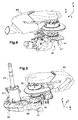
- the power plant includes a fastening means including a crown 90 of screws and a plurality of centering pins 91 visible on the figure 5 especially.
- the centering pins have the function of correctly positioning the crankcase relative to the flat housing.
- the output shaft 41 is then parallel to the rotor mast 21.
- this output shaft 41 is offset in particular longitudinally with respect to the rotor mast 21.
- the pylon 23 is fixed to the front section 22 'of the flat housing, while the turbine engine 40 is attached to the rear section 22 "of the flat housing 22.
- crankcase 42 is longitudinally offset from the pylon 23, and is not in contact with this pylon 23.
- This arrangement makes it possible in particular to have a firewall 80 between the crankcase 42 and the pylon 23.
- This firewall can, more generally, separate the turbine engine 40 from the power transmission gearbox 20 to isolate the turbine engine in a compartment defining a zone called "hot zone".
- the firewall then comprises several sections 81, 82, 83 such as a vertical pan 81 separating the crankcase 42 and the pylon 23, a horizontal flange 82 separating the upper face 24 'of the flat housing of the engine. turbine then another vertical pan 83 separating the crankcase 42 and a side face 22 '"of the flat housing 22.
- this arrangement makes it possible to implement at least one rotational speed reduction stage 25 comprising a large-diameter gear wheel, usually referred to as a "big wheel 26".
- the output shaft 41 of the turbine engine 40 can mesh directly or indirectly with a large wheel 26.
- the power plant includes a splined connection 95 between the output shaft 41 and the power transmission gearbox 20.
- the fluted connection presented on the figure 6 includes a splined tip 95 integral with the output shaft 41. This splined tip 95 may then be a part of the output shaft 41.
- the splined connection may also include a freewheel 30.
- the freewheel 30 comprises a driving portion 32 cooperating with a driven portion 33 via rollers or rollers 31.
- the freewheel 30 may also comprise interposed rolling means 34 between the driving portion 32 and the driven portion 33.
- rolling means 35 can also guide the rotation of the driven portion 33.
- the splined tip 95 of the output shaft 41 is then engaged with the driving portion 32 of the free wheel 30 of the power transmission gearbox.
- the driven portion of the freewheel 30 then meshes with a toothed wheel 26.
- the turbine engine 40 may comprise a dynamic seal 85 for isolating the inside INT of the turbine engine 40 from an EXT medium located outside this turbine engine 40. This dynamic seal 85 is then traversed by the output shaft 41.
- the driven portion of the freewheel 30 can also mesh gears to rotate an appendix shaft 36.
- This auxiliary shaft can rotate a rotor for controlling the yaw movement of the aircraft 1 for example.
- This arrangement thus makes it possible to obtain a power plant equipped with a compact turbine engine extending in elevation from a flat casing of a power transmission gearbox.
- this arrangement makes it possible to minimize the impacts of the installation of a heat exchanger 60 on this turbine engine.
- the heat exchanger 60 extends longitudinally from the turbine engine 40 in the extension of the turbine engine 40 and the rotor mast 21.
- the rotor mast 21 is longitudinally in front of the turbine engine 40, while the heat exchanger 60 is located longitudinally behind the turbine engine 40.
- the invention allows the arrangement of a compact turbine engine cooperating with a heat exchanger.
- This turbine engine 40 may comprise a gas turbine arranged within the crankcase for driving the output shaft.
- This gas turbine 50 is equipped with a gas generator followed by at least one turbine.
- the gas generator draws fresh air from an EXT medium outside the turbine engine to generate hot gases rotating at least one turbine, 53, 54.
- the gas generator comprises on the one hand a compressor 51 provided with at least one compression stage and, secondly, a combustion chamber 52.
- the turbine engine may have a driving turbine 53 connected to the compressor and then a working turbine 54 integral with a working shaft 55.
- the gas turbine extends in elevation.
- the combustion chamber is for example located above the compressor, the working turbine being located above the combustion chamber.
- the working shaft then passes through the combustion chamber and the compressor is directed parallel to the rotor mast 21.
- the working shaft 55 can be confused with the output shaft 41.
- a gear speed reducer 45 is possibly interposed in the crankcase 42 between the working shaft 55 and the output shaft 41.
- the speed reducer 45 can thus comprise gears 46 for driving the output shaft. 41 under the impetus of the working shaft.
- the turbine engine may comprise gears 47 which are engaged by an intermediate shaft 55 'of the gas generator and which are mechanically connected to accessories 48.
- crankcase 42 can then be split into a turbine casing 43 enclosing the gas turbine, and a gear housing 44 enclosing the speed reducer 45.
- the gears 47 may be arranged in the gearbox housing.
- the turbine casing then represents an upper casing enclosing the gas turbine, the gear housing representing a lower casing enclosing a speed reducer 45 and gears connected to accessories.
- the heat exchanger can aim to heat the fresh air compressed by the compressor of the gas turbine before entering the combustion chamber.
- the heat exchanger 60 comprises a heat exchange unit 64 supplied with fresh air from the compressor 51 by a first inlet pipe 61.
- the heat exchange block 64 supplies hot air to the combustion chamber. 52 by a first outlet pipe 62.
- the heat exchange block 64 is supplied with hot gas from the gas turbine by a second inlet pipe 63.
- the heat exchange block 64 expels the hot gas to the atmosphere through a second outlet pipe 65.
- the power plant 10 presented on the figure 1 comprises a first lubrication system 110 for lubricating the power transmission box 20.
- This first lubrication system 110 for example injects a mineral oil into the flat housing 22 to lubricate the gears of the reduction stages 25.
- the power plant has a second lubrication system 120 for lubricating the turbine engine 40.
- the second system 120 injects for example a synthetic oil into the crankcase.
- suspension means 130 include for example suspension bars 131 extending obliquely from the pylon 23 to the mechanical floor 6
- suspension means may include antivibration members.
- suspension members 140 are optionally interposed between the flat housing 22 and the mechanical floor 6, for example between the lower face 24 "and the mechanical floor 6.
- the power plant is stationary relative to the mechanical floor, in the sense that this installation does not include a member that tilts to move a rotor from a lift position to a tractive position for example.
- the pylon and the turbine engine are stationary relative to the flat housing, and are not tilting.
Landscapes
- Engineering & Computer Science (AREA)
- Mechanical Engineering (AREA)
- Chemical & Material Sciences (AREA)
- Combustion & Propulsion (AREA)
- General Engineering & Computer Science (AREA)
- Aviation & Aerospace Engineering (AREA)
- General Details Of Gearings (AREA)
- Gear Transmission (AREA)
Description
- La présente invention concerne une installation motrice modulaire ainsi qu'un aéronef muni d'un rotor de sustentation entraîné en rotation par cette installation motrice.
- Une installation motrice d'un tel aéronef comporte usuellement un moteur à turbine entraînant une boîte de transmission de puissance principale.
- Usuellement, un moteur à turbine comprend une turbine à gaz possédant un générateur de gaz mettant en rotation une turbine de travail. Cette turbine de travail peut être une turbine dite « turbine libre » indépendante du générateur de gaz. Le générateur de gaz comporte généralement au moins un étage de compression alimentant en air compressé une chambre de combustion.
- La boîte de transmission de puissance principale inclut un mât rotor mettant en rotation le rotor de sustentation. De plus, la boîte de transmission de puissance peut comporter une sortie pour l'entraînement d'un rotor de contrôle du mouvement en lacet de l'aéronef par exemple.
- Des moyens de liaison et de renvoi d'angle sont alors éventuellement interposés entre la turbine de travail et la boîte de transmission de puissance principale. Par exemple, de tels moyens de liaison incluent des organes autorisant des désalignements angulaires entre deux arbres en rotation.
- Un moteur à turbine est généralement disposé horizontalement sur un plancher mécanique. Autrement dit, un arbre de sortie du moteur à turbine se situe en position horizontale. A l'inverse, un plancher mécanique porte la boîte de transmission de puissance dans une position sensiblement verticale, le mât rotor mis en rotation par les engrenages de la boîte de transmission étant sensiblement vertical.
- Les moteurs à turbine d'ancienne génération présentent généralement une masse et un encombrement importants qui peuvent rendre leur installation délicate. De plus, ces moteurs à turbine d'ancienne génération peuvent présenter une consommation de carburant relativement élevée.
- Certains moteurs à turbine modernes sont cependant relativement compacts. On connaît notamment des moteurs à turbine comprenant un seul étage de compression et une chambre de combustion dite « inversée » permettant de restreindre fortement l'encombrement de ce moteur à turbine. On nomme un tel moteur à turbine « moteur à turbine compact » par commodité et pour l'identifier aisément.
- Pour améliorer les performances d'un moteur à turbine compact et notamment sa consommation en carburant, l'installation motrice peut comprendre un échangeur thermique. Si le moteur à turbine est compact, l'échangeur thermique s'avère au contraire volumineux. L'échangeur thermique permet par exemple de préchauffer de l'air entre la sortie d'un étage de compression du moteur à turbine et une chambre de combustion du moteur à turbine, en utilisant les gaz chauds prélevés à la sortie dudit moteur à turbine.
- L'échangeur thermique est alors fixé au moteur à turbine pour réchauffer l'air frais compressé par le générateur de gaz avant son entrée dans la chambre de combustion.
- Ainsi, un air frais est aspiré dans le moteur à turbine puis est comprimé par chaque étage de compression. L'air frais comprimé est dirigé dans l'échangeur thermique afin d'être réchauffé avant d'atteindre la chambre de combustion. Dès lors, l'air comprimé est enflammé conjointement avec du carburant de manière à générer un gaz chaud se détendant dans au moins une turbine. Ainsi le moteur à turbine peut comprendre une turbine liée aux étages du compresseur et une turbine libre de travail qui sont mises en rotation par ledit gaz chaud. Le gaz chaud est ensuite collecté par l'échangeur thermique pour réchauffer l'air frais aspiré par le moteur à turbine, avant d'être libéré dans l'atmosphère.
- L'ensemble comprenant un moteur à turbine compact et un échangeur s'avère alors encombrant par rapport à un moteur classique, mais peut par contre présenter une consommation de carburant limitée par exemple.
- Cependant, l'agencement d'un tel ensemble n'a rien d'évident.
- En effet, la mise en place de l'échangeur thermique peut induire une augmentation de la largeur et/ou de la hauteur et/ou de la longueur des capots de l'aéronef. La surface totale, et notamment frontale, de l'aéronef est alors accrue par rapport à une installation classique. Il peut en résulter une augmentation de la traînée aérodynamique de l'aéronef
- L'agencement d'un moteur à turbine compact couplé à un échangeur thermique peut aussi engendrer une modification sensible de la position du centre de gravité de l'aéronef pouvant engendrer des impacts néfastes sur la dérive de l'aéronef par exemple. La dérive et l'empennage doivent alors notamment être dimensionnés en conséquence pour garantir la stabilité statique de l'appareil.
- Le document
EP 1.216.190 décrit un moteur et une boîte de transmission intégrés. - Un moteur à turbine est monté dans un boîtier, un moyen de transmission de puissance étant intégré au boîtier et relié au moteur à turbine. Le moyen de transmission de puissance est monté dans un carter, ce carter et le boîtier étant intégrés ensemble en tant qu'unique unité.
- Le moteur à turbine comporte un arbre de sortie horizontal pour entraîner le moyen de transmission de puissance.
- Le document
FR 2.956.700 - Le document
US 5.226.350 décrit un aéronef comprenant un anneau entourant deux rotors contrarotatifs. Un moteur est agencé au sein de l'anneau pour entraîner en rotation un moyeu portant les rotors contrarotatifs. Le moteur est relié au moyeu par un arbre long tolérant des désalignements axiaux, angulaires et/ou de parallélisme entre le moyeu et le moteur. - Le document
US 5.108.043 décrit une installation motrice d'un hélicoptère comprenant deux moteurs. Chaque moteur entraîne une boîte de transmission de puissance via un arbre de transmission portant des cannelures à une première extrémité et portant un pignon d'engrenage à l'autre extrémité. - Le document
EP 0760 777 présente une boîte de transmission de puissance munie d'un train d'engrenage épicycloïdal. De plus, un moteur peut être relié à la boîte de transmission de puissance par le biais de moyens de renvoi d'angle. - Le document
DE 200 06 526 présente un arbre entraînant un rotor par une courroie. - Par suite, ces documents ne fournissent pas un enseignement relatif à l'agencement d'une installation motrice comprenant une boîte de transmission de puissance qui est entraînée en rotation par un moteur à turbine compact coopérant avec un échangeur thermique.
- On connaît aussi les documents
US 2005/115770 A1 ,US 5823470 A ,US 5054716 A ,GB 940024 A US 2011/121127 A1 etFR 2905983 A1 - Le document
US 2005/115770 A1 propose une installation munie d'une boîte de transmission basculante. - Le document
US 5823470 A décrit un aéronef muni de deux rotors basculants. - Le document
US 5054716 A décrit aussi un aéronef convertible muni d'un turbomoteur engrenant une boîte de transmission munie d'un mât. - La présente invention a alors pour objet de proposer une telle installation motrice.
- Selon l'invention, une installation motrice est munie d'une boîte de transmission de puissance et d'un moteur à turbine, la boîte de transmission de puissance comprenant un mât rotor sensiblement vertical qui est apte à mettre en rotation un moyeu d'un rotor, le moteur à turbine comprenant un arbre de sortie pour mettre en mouvement ladite boîte de transmission de puissance, l'installation motrice ayant un échangeur thermique fixé sur le moteur à turbine.
- Cette installation motrice est notamment remarquable en ce que :
- la boîte de transmission de puissance comporte au moins un étage de réduction de vitesse de rotation qui est agencé dans un carter plat et un pylône reposant sur une face supérieure du carter plat, le pylône étant traversé par le mât rotor,
- le moteur à turbine comporte un carter moteur, l'arbre de sortie saillant du carter moteur, l'arbre de sortie pénétrant dans le carter plat lorsque le carter moteur est disposé sur la face supérieure du carter plat, l'arbre de sortie étant sensiblement parallèle au mât rotor, le carter moteur étant longitudinalement décalé par rapport au pylône et n'étant pas en contact avec ce pylône,
- l'échangeur thermique s'étend longitudinalement en arrière du moteur à turbine, ledit mât rotor étant à l'inverse situé longitudinalement devant le moteur à turbine.
- Cette installation n'est pas une installation basculante. En effet, le pylône est immobile par rapport au carter plat, le moteur à turbine étant immobile par rapport au carter plat, et l'installation étant immobile par rapport à un plancher mécanique
- Autrement dit, le moteur à turbine est disposé entre le mât rotor et l'échangeur thermique au regard d'une direction longitudinale allant de l'avant vers l'arrière de l'installation motrice et/ou d'un véhicule muni de cette installation motrice. Un observateur regardant l'installation motrice de côté selon une direction transversale peut noter cette caractéristique.
- L'échangeur thermique peut être strictement placé dans une position longitudinale en étant agencé dans un plan antéropostérieur de symétrie de l'installation motrice et d'un véhicule.
- A titre de variante, l'échangeur thermique est agencé de manière oblique en étant placé dans un plan oblique qui s'étend en élévation et longitudinalement en présentant une angulation avec le plan antéropostérieur. Cette angulation est alors visible par un observateur regardant l'installation motrice selon une direction en élévation.
- Le carter plat est qualifié de « plat » dans la mesure où sa dimension en élévation est très faible comparé à ses dimensions longitudinale et transversale.
- Par exemple, la dimension en élévation est d'environ 150 millimètres alors que la dimension transversale peut être de l'ordre de 500 millimètres ce qui permet l'insertion d'une grande roue, la dimension longitudinale pouvant être de l'ordre d'un mètre en permettant l'insertion d'un train de pignons. Le pylône peut présenter une dimension en élévation d'environ 400 millimètres et un diamètre de l'ordre de 300 millimètres. Ces données chiffrées sont fournies à titre d'exemple pour notamment illustrer le caractère plat du carter plat.
- Cette installation motrice propose un agencement muni de deux modules indépendants avant d'être fixés l'un à l'autre, à savoir une boîte de transmission de puissance et un moteur à turbine tel qu'avantageusement un moteur à turbine compact. Ces deux modules sont donc distincts et présentent deux carters distincts.
- Le moteur à turbine et la boîte de transmission sont donc indépendants et autonomes. Par exemple, le moteur à turbine et la boîte de transmission peuvent alors être certifiés indépendamment l'un de l'autre par les autorités compétentes.
- Une liaison mécanique mettant en oeuvre un arbre de sortie vertical permet de lier mécaniquement ces deux modules.
- Ainsi, le moteur à turbine peut être démonté d'un véhicule, sans impacter la boîte de transmission de puissance, et inversement. Un opérateur peut remplacer un moteur à turbine défectueux par un autre moteur à turbine sans difficulté.
- Le moteur à turbine est relié mécaniquement à la boîte de transmission de puissance par un arbre de sortie saillant verticalement du carter moteur. Cette caractéristique confère à l'arbre de sortie une souplesse d'utilisation pouvant tolérer un désalignement entre le moteur à turbine et la boîte de transmission de puissance.
- Par ailleurs, cette installation motrice ne nécessite pas d'implémenter des moyens de liaison ou de renvoi d'angle entre le moteur à turbine et la boîte de transmission de puissance puisque l'arbre de sortie du moteur à turbine est inséré directement dans la boîte de transmission de puissance.
- En outre, cette installation motrice permet de ne pas dégrader indument les performances aérodynamiques d'un aéronef.
- En effet, on rappelle que l'agencement d'un moteur à turbine associé à un échangeur thermique peut impacter la surface frontale d'un aéronef.
- Cependant, l'installation motrice selon l'invention suggère de disposer un moteur à turbine dans une position sensiblement verticale contrairement à des réalisations usuelles.
- Dès lors, l'échangeur thermique peut s'étendre longitudinalement sensiblement en position horizontale dans le prolongement du moteur à turbine dans des dimensions de capots usuels, et donc dans l'espace alloué usuellement à une installation motrice.
- Lorsque l'installation motrice est agencée sur un aéronef, l'échangeur thermique a alors une influence restreinte sur la surface frontale de l'aéronef en se situant dans le prolongement du moteur à turbine.
- De plus, le moteur à turbine étant associé à un échangeur thermique, ce moteur à turbine peut être un moteur à turbine compact ayant de fait un encombrement limité. Par conséquent, ce moteur à turbine s'étend verticalement sur une hauteur restant raisonnable. En complément, la boîte de transmission de puissance peut comprendre un carter plat du fait de l'emmanchement direct de l'arbre de sortie dans cette boîte de transmission de puissance. La hauteur de l'installation motrice est ainsi optimisée.
- En outre, le moteur à turbine s'étend longitudinalement sur une très courte distance permettant de minimiser l'impact de l'échangeur thermique sur le centrage de l'aéronef. L'ensemble comprenant le moteur à turbine et l'échangeur thermique s'étend en effet longitudinalement sur une distance minimisée par l'agencement vertical du moteur à turbine. Cet agencement a aussi un effet positif sur la position du centre de gravité de l'aéronef, contrairement à des solutions ayant un impact sur la dérive et l'empennage d'un aéronef. En effet, le bras de levier de l'ensemble comprenant un moteur à turbine et un échangeur par rapport à un mât rotor tend à être réduit, ce qui permet de rapprocher le centre de gravité de l'aéronef de l'axe de rotation du rotor.
- Par conséquent, la synergie de ces organes de cette installation motrice permet d'obtenir une installation motrice pouvant présenter de multiples avantages inattendus.
- L'installation motrice peut de plus comporter une ou plusieurs des caractéristiques qui suivent.
- Ainsi, l'installation motrice peut comporter une cloison pare-feu agencée entre le carter moteur et ledit pylône. En effet, le carter moteur et le pylône sont éloignés l'un de l'autre ce qui permet l'insertion d'une cloison pare-feu.
- Cette cloison pare-feu peut comporter plusieurs pans pour être interposée de manière plus générale entre la boîte de transmission de puissance et le moteur à turbine. Dès lors, la cloison pare feu est pourvue par exemple d'un pan vertical séparant le moteur à turbine du pylône de la boîte de transmission de puissance, voire notamment un pan horizontal interposé entre le moteur à turbine et le carter plat.
- Par ailleurs, le carter plat s'étend éventuellement longitudinalement d'un tronçon avant portant le pylône vers un tronçon arrière portant le moteur à turbine. Cette caractéristique permet notamment de bien séparer le carter moteur du pylône.
- De plus, le carter plat peut alors accueillir un étage de réduction de puissance muni d'une grande roue. Une telle grande roue présente l'avantage d'être robuste et moins onéreuse qu'un engrenage épicycloïdal par exemple.
- L'arbre de sortie peut alors engrener la grande roue directement, ou indirectement via une roue libre par exemple. Une telle roue libre présente l'avantage d'autoriser une autorotation d'un rotor de sustentation en cas de blocage accidentel du moteur à turbine.
- En effet, l'installation motrice peut comporter une liaison cannelée disposée entre l'arbre de sortie et la boîte de transmission de puissance.
- Une telle liaison cannelée comporte par exemple un embout cannelé solidaire de l'arbre de sortie
- Selon une réalisation, l'embout cannelé engrène une grande roue, dénommée parfois « engrenage à grande roue dentée ». La grande roue est une roue circulaire dentée présentant de fait un grand rapport de démultiplication.
- Par contre, selon une autre réalisation, cet embout cannelé engrène une roue libre de la boîte de transmission de puissance, cette roue libre engrenant un étage de réduction de vitesse de rotation. Dès lors, la roue libre engrène par exemple une grande roue.
- Par ailleurs, le moteur à turbine peut comprendre une turbine à gaz munie d'un générateur de gaz et d'une turbine de travail solidaire d'un arbre de travail.
- L'arbre de travail et l'arbre de sortie peuvent être confondus et former un même arbre.
- Cependant, l'arbre de travail et l'arbre de sortie peuvent être distincts. Dès lors, l'arbre de travail est favorablement sensiblement parallèle au mât rotor, et donc à l'arbre de sortie.
- Le mât rotor, l'arbre de sortie et l'arbre de travail étant parallèles les uns aux autres, l'installation motrice ne nécessite pas de moyens de renvoi d'angle pour les relier deux à deux.
- Par suite, le moteur à turbine comporte éventuellement un réducteur de vitesse à engrenages qui est interposé dans le carter moteur entre l'arbre de travail et l'arbre de sortie. On comprend que le carter moteur peut alors posséder un carter dénommé « carter de turbine » enserrant la turbine à gaz, et un carter dénommé « carter de réducteur » enserrant le réducteur de vitesse. Le carter de turbine et le carter de réducteur sont solidaires l'un de l'autre. Le moteur à turbine est ainsi modulaire en possédant un module « turbine à gaz » et un module « réducteur de vitesse ».
- Dès lors, la vitesse de rotation de l'arbre de travail peut être de l'ordre de 10000 à 50000 tours par minute, alors que la vitesse de rotation de l'arbre de sortie est réduite à 6000 à 9000 tours par minute par exemple. Les engrenages de la boîte de transmission de puissance peuvent alors réduire cette vitesse de rotation pour atteindre une vitesse de rotation de l'ordre de 400 tours par minute au niveau du mât rotor par exemple.
- Par ailleurs, l'installation motrice peut comporter un moyen de liaison pour fixer le carter moteur au carter plat, ce moyen de liaison incluant une couronne de vis et une pluralité de pions de centrage. Ce moyen de liaison permet de guider le moteur à turbine vers la position adéquate à l'aide des pions de guidage, et de fixer ce moteur à turbine à la boîte de transmission de puissance à l'aide de la couronne de vis.
- Une cloison pare-feu peut être disposée à l'interface entre le moteur à turbine et la boîte de transmission de puissance.
- En outre, l'arbre de sortie peut saillir dudit carter moteur sur une hauteur supérieure à 10 centimètres.
- L'arbre de sortie est alors suffisamment long pour être flexible. Un tel arbre de sortie peut ainsi autoriser la présence de déformées angulaires lors du montage du moteur à turbine sur la boîte de transmission de puissance.
- Le positionnement du moteur à turbine par rapport à la boîte de transmission doit être relativement précis pour ne pas induire un dysfonctionnement. Un désalignement trop important peut en effet générer des efforts importants sur les organes de la boîte de transmission de puissance risquant de conduire à une usure prématurée.
- La présence d'un arbre de sortie « long » permet d'offrir une certaine latitude de réglage à un opérateur. De plus, la présence de pions de guidage favorise un positionnement correct du moteur à turbine.
- Par ailleurs, l'installation motrice peut comporter un premier système de lubrification de la boîte de transmission de puissance et un deuxième système de lubrification du moteur à turbine.
- La structure modulaire de l'installation motrice permet la mise en place de systèmes de lubrification personnalisés.
- Ainsi, le premier système de lubrification comporte éventuellement une huile minérale présentant une haute résistance à des pressions d'engrènement, ledit deuxième système de lubrification du moteur à turbine comportant une huile synthétique présentant une faible viscosité et une bonne résistance aux hautes températures.
- Le moteur à turbine peut comporter un joint dynamique traversé par l'arbre de sortie pour isoler un espace interne du moteur à turbine d'un milieu extérieur au moteur à turbine. Ainsi, le joint dynamique vise par exemple à éviter une fuite d'un liquide de lubrification.
- En outre, le pylône comporte éventuellement des moyens de suspension de la boîte de transmission de puissance à un plancher mécanique. De tels moyens de suspension peuvent inclure des barres de suspension obliques s'étendant du pylône vers un plancher.
- Le carter plat peut aussi comprendre un dispositif de suspension permettant de le suspendre à un plancher.
- L'invention vise aussi un aéronef muni d'un rotor de sustentation comprenant un moyeu et une pluralité de pales. Cet aéronef comporte une installation motrice du type décrit précédemment.
- Dès lors, ledit aéronef peut comporter un plancher mécanique portant ladite installation motrice, cette installation motrice étant immobile par rapport audit plancher mécanique.
- L'installation motrice n'est donc pas un ensemble basculant au sens des documents
US 2005/115770 A1 ,US 5823470 A ,US 5054716 A par exemple. - L'invention et ses avantages apparaîtront avec plus de détails dans le cadre de la description qui suit avec des exemples de réalisations donnés à titre illustratif en référence aux figures annexées qui représentent :
- la
figure 1 , un schéma présentant un aéronef selon l'invention, - la
figure 2 , une vue d'une boîte de transmission de puissance selon l'invention, - les
figures 3 et4 , une vue d'un moteur à turbine couplé à un échangeur thermique, - la
figure 5 , une vue d'une installation motrice, et - la
figure 6 , une coupe présentant un arbre de sortie engrenant la boîte de transmission de puissance. - Les éléments présents dans plusieurs figures distinctes sont affectés d'une seule et même référence.
- On note que trois directions X, Y et Z orthogonales les unes par rapport aux autres sont représentées sur certaines figures.
- La première direction X est dite longitudinale.
- La deuxième direction Y est dite transversale.
- Enfin, la troisième direction Z est dite en élévation. L'expression « en élévation » est relative à toute direction parallèle à la troisième direction Z.
- La
figure 1 présente un aéronef 1 muni d'une installation motrice entraînant un rotor 2. Les autres organes de l'aéronef ne sont pas représentés pour ne pas alourdir lafigure 1 . - Le rotor 2 possède un moyeu 3 portant une pluralité de pales 4. De plus, le rotor 2 comporte par exemple un ensemble de plateaux de commande 5 pour contrôler le pas des pales 4 cycliquement et/ou collectivement.
- Pour mettre en rotation le rotor 2, l'aéronef est équipé d'une installation motrice 10 porté par un plancher mécanique 6.
- Cette installation motrice 10 possède un moteur à turbine 40 couplé à un échangeur thermique. Cet échangeur thermique permet de réchauffer l'air comprimé par un générateur de gaz du moteur à turbine avant son admission dans une chambre de combustion.
- Le moteur à turbine met alors en rotation une boîte de transmission de puissance 20 munie d'un mât rotor 21 portant le moyeu 3.
- A cet effet, la boîte de transmission de puissance 20 est pourvue d'au moins un étage 25 de réduction de la vitesse de rotation pour entraîner le mât rotor 21 à une vitesse de l'ordre de 400 tours par minute. Chaque étage 25 de réduction de la vitesse de rotation comporte des engrenages agencés dans un carter plat 22.
- En référence à la
figure 2 , le carter plat s'étend en élévation d'une face inférieure 24" vers une face supérieure 24', et longitudinalement d'un tronçon avant 22' vers un tronçon arrière 22". La dimension en élévation du carter plat est inférieure aux dimensions longitudinale et transversale de ce carter plat. C'est la raison pour laquelle le carter est qualifié de « carter plat ». - En outre, le mât rotor 21 traverse un pylône 23 fixé à la face supérieure 24' du carter plat 22. Ce mât rotor 21 s'étend alors le long d'une direction en élévation sensiblement dirigée selon la pesanteur lorsque l'aéronef est au sol.
- En référence à la
figure 1 , le moteur à turbine 40 est muni d'une turbine à gaz 50 disposée dans un carter moteur 42. - De plus, le moteur à turbine 40 est pourvu d'un arbre de sortie 41 mis en rotation par la turbine à gaz 50. Cet arbre de sortie saille alors du carter moteur 42, préférentiellement sur une hauteur H supérieure à 10 centimètres.
- Par suite, l'arbre de sortie 41 est inséré dans le carter plat. Le carter moteur est alors fixé sur la face supérieure 24' du carter plat. Par exemple, l'installation motrice comporte un moyen de fixation incluant une couronne 90 de vis et une pluralité de pions 91 de centrage visibles sur la
figure 5 notamment. - Les pions de centrage ont pour fonction de positionner correctement le carter moteur par rapport au carter plat.
- En référence à la
figure 1 , l'arbre de sortie 41 est alors parallèle au mât rotor 21. Cependant, cet arbre de sortie 41 est décalé notamment longitudinalement par rapport au mât rotor 21. En effet, le pylône 23 est fixé au tronçon avant 22' du carter plat, alors que le moteur à turbine 40 est fixé au tronçon arrière 22" du carter plat 22. - Par conséquent, le carter moteur 42 est longitudinalement décalé par rapport au pylône 23, et n'est pas en contact avec ce pylône 23.
- Cet agencement permet notamment de disposer une cloison pare-feu 80 entre le carter moteur 42 et le pylône 23.
- Cette cloison pare-feu peut, plus généralement, séparer le moteur à turbine 40 de la boîte de transmission de puissance 20 pour isoler le moteur à turbine dans un compartiment définissant une zone dite « zone chaude ».
- Par exemple, la cloison pare-feu comprend alors plusieurs pans 81, 82, 83 tels qu'un pan vertical 81 séparant le carter moteur 42 et le pylône 23, un pan horizontal 82 séparant la face supérieure 24' du carter plat du moteur à turbine puis un autre pan vertical 83 séparant le carter moteur 42 et une face latérale 22'" du carter plat 22.
- De plus, cet agencement permet d'implémenter au moins un étage 25 de réduction de vitesse de rotation comprenant une roue dentée de grand diamètre dénommé usuellement « grande roue 26 ».
- Dès lors, l'arbre de sortie 41 du moteur à turbine 40 peut engrener directement ou indirectement une grande roue 26.
- Par conséquent, l'installation motrice inclut une liaison cannelée 95 entre l'arbre de sortie 41 et la boîte de transmission de puissance 20.
- La liaison cannelée présentée sur la
figure 6 inclut un embout cannelé 95 solidaire de l'arbre de sortie 41. Cet embout cannelé 95 peut alors être une partie de l'arbre de sortie 41. - De plus, la liaison cannelée peut aussi inclure une roue libre 30. La roue libre 30 comprend une partie menante 32 coopérant avec une partie menée 33 via des rouleaux ou des galets 31. La roue libre 30 peut aussi comprendre des moyens de roulement 34 interposés entre la partie menante 32 et la partie menée 33. Par ailleurs des moyens de roulement 35 peuvent aussi guider la rotation de la partie menée 33.
- L'embout cannelé 95 de l'arbre de sortie 41 est alors en prise avec la partie menante 32 de la roue libre 30 de la boîte de transmission de puissance. La partie menée de la roue libre 30 engrène alors une roue dentée 26.
- Par ailleurs, le moteur à turbine 40 peut comprendre un joint dynamique 85 pour isoler l'intérieur INT du moteur à turbine 40 d'un milieu EXT situé à l'extérieur de ce moteur à turbine 40. Ce joint dynamique 85 est alors traversé par l'arbre de sortie 41.
- En référence à la
figure 1 , la partie menée de la roue libre 30 peut aussi engrener des engrenages pour mettre en rotation un arbre annexe 36. Cet arbre annexe peut mettre en rotation un rotor de contrôle du mouvement en lacet de l'aéronef 1 par exemple. - Cet agencement permet donc d'obtenir une installation motrice munie d'un moteur à turbine compact s'étendant en élévation à partir d'un carter plat d'une boîte de transmission de puissance.
- De plus, cet agencement permet de minimiser les impacts de l'installation d'un échangeur thermique 60 sur ce moteur à turbine. En effet, l'échangeur thermique 60 s'étend longitudinalement à partir du moteur à turbine 40 dans le prolongement de ce moteur à turbine 40 et du mât rotor 21.
- Par suite, le mât rotor 21 se trouve longitudinalement devant le moteur à turbine 40, alors que l'échangeur thermique 60 se trouve longitudinalement en arrière du moteur à turbine 40.
- Ainsi, l'invention permet l'agencement d'un moteur à turbine compact coopérant avec un échangeur thermique.
- Ce moteur à turbine 40 peut comprendre une turbine à gaz agencée au sein du carter moteur pour l'entraînement de l'arbre de sortie.
- Cette turbine à gaz 50 est équipée d'un générateur de gaz suivie d'au moins une turbine. Le générateur de gaz aspire l'air frais à partir d'un milieu EXT extérieur au moteur à turbine pour générer des gaz chauds mettant en rotation au moins une turbine, 53, 54. Ainsi, le générateur de gaz comporte d'une part un compresseur 51 muni d'au moins un étage de compression et, d'autre part, une chambre de combustion 52.
- De plus, le moteur à turbine peut posséder une turbine d'entrainement 53 liée au compresseur puis une turbine de travail 54 solidaire d'un arbre de travail 55.
- La turbine à gaz s'étend en élévation. La chambre de combustion est par exemple située au dessus du compresseur, la turbine de travail étant située au dessus de la chambre de combustion. L'arbre de travail traverse alors la chambre de combustion et lé compresseur en étant dirigé parallèlement au mât rotor 21.
- Par ailleurs, l'arbre de travail 55 peut être confondu avec l'arbre de sortie 41.
- Toutefois, un réducteur 45 de vitesse à engrenages est éventuellement interposé dans le carter moteur 42 entre l'arbre de travail 55 et l'arbre de sortie 41. Le réducteur 45 de vitesse peut ainsi comprendre des engrenages 46 pour entraîner l'arbre de sortie 41 sous l'impulsion de l'arbre de travail.
- De même, le moteur à turbine peut comprendre des engrenages 47 qui sont engrenés par un arbre intermédiaire 55' du générateur de gaz et qui sont mécaniquement reliés à des accessoires 48.
- En référence aux
figures 3 et4 , le carter moteur 42 peut alors être scindé en un carter turbine 43 enserrant la turbine à gaz, et un carter de réducteur 44 enserrant le réducteur 45 de vitesse. Les engrenages 47 peuvent être agencés dans le carter de réducteur. Le carter turbine représente alors un carter supérieur enserrant la turbine à gaz, le carter réducteur représentant un carter inférieur enserrant un réducteur 45 de vitesse et des engrenages reliés à des accessoires. - En référence à la
figure 1 , l'échangeur thermique peut viser à réchauffer l'air frais comprimé par le compresseur de la turbine à gaz avant son entrée dans la chambre de combustion. - Dès lors, l'échangeur thermique 60 comporte un bloc d'échange thermique 64 alimenté en air frais provenant du compresseur 51 par une première conduite d'entrée 61. Le bloc d'échange thermique 64 alimente au contraire en air chaud la chambre de combustion 52 par une première conduite de sortie 62.
- Pour réchauffer l'air frais, le bloc d'échange thermique 64 est alimenté en gaz chaud provenant de la turbine à gaz par une deuxième conduite d'entrée 63. Le bloc d'échange thermique 64 expulse le gaz chaud vers l'atmosphère au travers d'une deuxième conduite de sortie 65.
- On se référera à la littérature pour obtenir une description d'un tel échangeur.
- Par ailleurs, l'installation motrice 10 présentée sur la
figure 1 comporte un premier système 110 de lubrification pour lubrifier la boîte de transmission de puissance 20. Ce premier système 110 de lubrification injecte par exemple une huile minérale dans le carter plat 22 pour lubrifier les engrenages des étages de réduction 25. - De même, l'installation motrice possède un deuxième système 120 de lubrification pour lubrifier le moteur à turbine 40. Le deuxième système 120 injecte par exemple une huile synthétique dans le carter moteur.
- En outre, l'installation motrice peut être fixée à un plancher 6 d'un aéronef par des moyens de suspension 130. Ces moyens de suspension 130 incluent par exemple des barres de suspension 131 s'étendant obliquement du pylône 23 vers le plancher mécanique 6. Ces moyens de suspension peuvent inclure des organes antivibratoires.
- De plus, des organes de suspension 140 sont éventuellement interposés entre le carter plat 22 et le plancher mécanique 6, par exemple entre la face inférieure 24" et ce plancher mécanique 6.
- Bien que suspendu, l'installation motrice est immobile par rapport au plancher mécanique, au sens où cette installation ne comporte pas un organe qui bascule pour déplacer un rotor d'une position sustentatrice vers une position tractive par exemple.
- Ainsi, le pylône et le moteur à turbine sont immobiles par rapport au carter plat, et de sont pas basculants.
- Naturellement, la présente invention est sujette à de nombreuses variations quant à sa mise en oeuvre. Bien que plusieurs modes de réalisation aient été décrits, on comprend bien qu'il n'est pas concevable d'identifier de manière exhaustive tous les modes possibles. Il est bien sûr envisageable de remplacer un moyen décrit par un moyen équivalent sans sortir du cadre de la présente invention.
Claims (17)
- Installation motrice (10) munie d'une boîte de transmission de puissance (20) et d'un moteur à turbine (40), la boîte de transmission de puissance (20) comprenant un mât rotor (21) sensiblement vertical qui est apte à mettre en rotation un moyeu (3) d'un rotor (2), le moteur à turbine (40) comprenant un arbre de sortie (41) pour mettre en mouvement ladite boîte de transmission de puissance (20), ladite installation motrice (10) ayant un échangeur thermique (60) fixé sur ledit moteur à turbine (40), caractérisée en ce que :- ladite boîte de transmission de puissance (20) comporte au moins un étage (25) de réduction de vitesse de rotation agencé dans un carter plat (22) et un pylône (23) reposant sur une face supérieure (24') dudit carter plat (22), ledit pylône (23) étant traversé par ledit mât rotor (21),- ledit moteur à turbine (40) comporte un carter moteur (42), ledit arbre de sortie (41) saillant dudit carter moteur (42), ledit arbre de sortie (41) pénétrant dans ledit carter plat (22) lorsque ledit carter moteur (42) est disposé sur ladite face supérieure (24'), ledit arbre de sortie (41) étant sensiblement parallèle au mât rotor (21), ledit carter moteur (42) étant longitudinalement décalé par rapport au pylône (23) et n'étant pas en contact avec ce pylône (23),- ledit échangeur thermique (60) s'étend longitudinalement en arrière dudit moteur à turbine (40), ledit mât rotor (21) étant à l'inverse situé longitudinalement devant ledit moteur à turbine (40).
- Installation motrice selon la revendication 1,
caractérisée en ce que ladite installation motrice (10) comporte une cloison pare-feu (80) agencée entre le carter moteur (42) et ledit pylône (23). - Installation motrice selon l'une quelconque des revendications 1 à 2,
caractérisée en ce que ledit carter plat (22) s'étend longitudinalement d'un tronçon avant (22') portant ledit pylône (23) vers un tronçon arrière (22") portant ledit moteur à turbine (40). - Installation motrice selon l'une quelconque des revendications 1 à 3,
caractérisée en ce que ledit moteur à turbine (40) comprend une turbine à gaz (50) munie d'un générateur de gaz (51, 52) et d'une turbine de travail (54) solidaire d'un arbre de travail (55), ledit arbre de travail (55) étant sensiblement parallèle au mât rotor (21). - Installation motrice selon l'une quelconque des revendications 1 à 4,
caractérisée en ce que ledit moteur à turbine (40) comporte un réducteur (45) de vitesse à engrenages qui est interposé dans le carter moteur (42) entre ledit arbre de travail (55) et ledit arbre de sortie (41). - Installation motrice selon l'une quelconque des revendications 1 à 5,
caractérisée en ce que ledit moteur à turbine (40) comporte un joint (85) dynamique traversé par ledit arbre de sortie (41) pour isoler un espace interne du moteur à turbine d'un milieu extérieur au moteur à turbine (40). - Installation motrice selon l'une quelconque des revendications 1 à 6,
caractérisé en ce que ladite installation motrice (10) comporte un moyen de liaison pour fixer le carter moteur (42) au carter plat (22), ledit moyen de liaison incluant une couronne (90) de vis et une pluralité de pions (91) de centrage. - Installation motrice selon l'une quelconque des revendications 1 à 7,
caractérisée en ce que ladite installation motrice (10) comporte une liaison cannelée (95) entre ledit arbre de sortie (41) et ladite boîte de transmission de puissance (20). - Installation motrice selon la revendication 8,
caractérisée en ce que ladite liaison cannelée (95) comporte un embout cannelé (95) solidaire de l'arbre de sortie (41), cet embout cannelé (41') engrenant une roue libre (30) de la boîte de transmission de puissance (20), ladite roue libre (30) engrenant un étage (25) de réduction de vitesse de rotation. - Installation motrice selon la revendication 9,
caractérisée en ce que ladite roue libre (30) engrène une grande roue (26). - Installation motrice selon l'une quelconque des revendications 1 à 10,
caractérisée en ce que ledit arbre de sortie (41) saille dudit carter moteur (42) sur une hauteur (H) supérieure à 10 centimètres. - Installation motrice selon l'une quelconque des revendications 1 à 11,
caractérisée en ce que ladite installation motrice (10) comporte un premier système (110) de lubrification de la boîte de transmission de puissance (20) et un deuxième système (120) de lubrification du moteur à turbine (40). - Installation motrice selon la revendication 12,
caractérisée en ce que ledit premier système (110) de lubrification comporte une huile minérale, ledit deuxième système (120) de lubrification du moteur à turbine comportant une huile synthétique. - Installation motrice selon l'une quelconque des revendications 1 à 13,
caractérisée en ce que ledit pylône (23) comporte des moyens de suspension (130) de la boîte de transmission de puissance (20) à un plancher mécanique (6). - Installation motrice selon l'une quelconque des revendications 1 à 14,
caractérisée en ce que ledit pylône et ledit moteur à turbine sont immobiles par rapport audit carter plat. - Aéronef (1) muni d'un rotor (2) de sustentation comprenant un moyeu (2) et une pluralité de pales (4),
caractérisé en ce que ledit aéronef (1) comporte une installation motrice (10) selon l'une quelconque des revendications 1 à 15. - Aéronef selon la revendication 16,
caractérisé en ce que ledit aéronef comporte un plancher mécanique portant ladite installation motrice (10), cette installation motrice étant immobile par rapport audit plancher mécanique.
Applications Claiming Priority (1)
| Application Number | Priority Date | Filing Date | Title |
|---|---|---|---|
| FR1301681A FR3008679B1 (fr) | 2013-07-16 | 2013-07-16 | Installation motrice modulaire et aeronef muni d'un rotor de sustentation |
Publications (2)
| Publication Number | Publication Date |
|---|---|
| EP2826709A1 true EP2826709A1 (fr) | 2015-01-21 |
| EP2826709B1 EP2826709B1 (fr) | 2016-08-24 |
Family
ID=49667204
Family Applications (1)
| Application Number | Title | Priority Date | Filing Date |
|---|---|---|---|
| EP14002129.6A Active EP2826709B1 (fr) | 2013-07-16 | 2014-06-20 | Installation motrice modulaire et aéronef muni d'un rotor de sustentation |
Country Status (4)
| Country | Link |
|---|---|
| US (1) | US9346541B2 (fr) |
| EP (1) | EP2826709B1 (fr) |
| CA (1) | CA2855244C (fr) |
| FR (1) | FR3008679B1 (fr) |
Cited By (8)
| Publication number | Priority date | Publication date | Assignee | Title |
|---|---|---|---|---|
| EP3059418A1 (fr) * | 2015-02-20 | 2016-08-24 | Pratt & Whitney Canada Corp. | Ensemble moteur composé avec une zone pare-feu délimitée |
| EP3059422A1 (fr) * | 2015-02-20 | 2016-08-24 | Pratt & Whitney Canada Corp. | Moteur turbocompound avec ensemble de support |
| US9869240B2 (en) | 2015-02-20 | 2018-01-16 | Pratt & Whitney Canada Corp. | Compound engine assembly with cantilevered compressor and turbine |
| US10408123B2 (en) | 2015-02-20 | 2019-09-10 | Pratt & Whitney Canada Corp. | Engine assembly with modular compressor and turbine |
| US10428734B2 (en) | 2015-02-20 | 2019-10-01 | Pratt & Whitney Canada Corp. | Compound engine assembly with inlet lip anti-icing |
| US10533500B2 (en) | 2015-02-20 | 2020-01-14 | Pratt & Whitney Canada Corp. | Compound engine assembly with mount cage |
| US10677154B2 (en) | 2015-02-20 | 2020-06-09 | Pratt & Whitney Canada Corp. | Compound engine assembly with offset turbine shaft, engine shaft and inlet duct |
| CN114435607A (zh) * | 2022-02-24 | 2022-05-06 | 重庆大学 | 一种带传动式倾转旋翼机传动系统 |
Families Citing this family (7)
| Publication number | Priority date | Publication date | Assignee | Title |
|---|---|---|---|---|
| FR3040691A1 (fr) * | 2015-09-08 | 2017-03-10 | Airbus Helicopters | Aeronef et groupe motoreducteur d'aeronef |
| RU2613099C1 (ru) * | 2016-02-20 | 2017-03-15 | Акционерное общество "АВИАЦИОННЫЕ РЕДУКТОРА И ТРАНСМИССИИ - ПЕРМСКИЕ МОТОРЫ" (АО "РЕДУКТОР - ПМ") | Главный редуктор вертолета |
| US10151247B2 (en) * | 2016-03-18 | 2018-12-11 | United Technologies Corporation | Heat exchanger suspension system with pipe-to-linkage spring rate ratio |
| US10669948B2 (en) | 2017-01-03 | 2020-06-02 | Raytheon Technologies Corporation | Geared turbofan with non-epicyclic gear reduction system |
| CN110857144B (zh) * | 2018-08-23 | 2023-05-23 | 上海峰飞航空科技有限公司 | 动力系统及包含其的飞行器 |
| US11313455B2 (en) * | 2018-10-05 | 2022-04-26 | Textron Innovations Inc. | Aircraft gearbox lubrication system with multiple lubrication subsystems |
| FR3166166A1 (fr) | 2024-09-06 | 2026-03-13 | Safran Helicopter Engines | Groupe propulsif pour un aeronef comprenant un turbomoteur et un reducteur |
Citations (13)
| Publication number | Priority date | Publication date | Assignee | Title |
|---|---|---|---|---|
| US2005111A (en) | 1931-04-09 | 1935-06-18 | Rca Corp | Amplifier |
| GB940024A (en) | 1959-12-04 | 1963-10-23 | Westland Aircraft Ltd | Improvements in or relating to mechanical gearing |
| US5054716A (en) | 1989-10-16 | 1991-10-08 | Bell Helicopter Textron Inc. | Drive system for tiltrotor aircraft |
| US5108043A (en) | 1991-03-29 | 1992-04-28 | Bell Helicopter Textron, Inc. | Twin engine helicopter accesssory drive |
| US5226350A (en) | 1992-06-22 | 1993-07-13 | United Technologies Corporation | Drive train assembly for a rotor assembly having ducted, coaxial counter-rotating rotors |
| EP0760777A1 (fr) | 1994-05-26 | 1997-03-12 | United Technologies Corporation | Train d'engrenages planetaires composes superposes pour un systeme de train moteur evolue pour helicoptere |
| US5823470A (en) | 1996-07-16 | 1998-10-20 | Mcdonnell Douglas Helicopter Co. | Split torque proprotor transmission |
| DE20006526U1 (de) | 2000-04-08 | 2000-06-29 | Guzicki, Gerd, Dipl.-Ing., 34246 Vellmar | Heckrotorantrieb für einen Modellhubschrauber |
| EP1216190A1 (fr) | 1999-09-30 | 2002-06-26 | Pratt & Whitney Canada Corp. | Moteur et unites de transmission integres pour aeronef a voilure tournante |
| US20050115770A1 (en) | 2001-11-07 | 2005-06-02 | Thierry Sandrart | Lubricating installation for rocking power transmission box |
| FR2905983A1 (fr) | 2006-09-20 | 2008-03-21 | Turbomeca | Dispositif d'insonorisation d'un moteur d'helicoptere a turbine a gaz, et moteur ainsi obtenu |
| US20110121127A1 (en) | 2009-11-26 | 2011-05-26 | Eurocopter | Power plant, a helicopter including such a power plant, and a method implemented by said power plant |
| FR2956700A1 (fr) | 2010-02-25 | 2011-08-26 | Turbomeca | Turbomachine a arbre vertical |
Family Cites Families (13)
| Publication number | Priority date | Publication date | Assignee | Title |
|---|---|---|---|---|
| US2625006A (en) * | 1947-11-25 | 1953-01-13 | Curtiss Wright Corp | Compound engine |
| US2933892A (en) * | 1957-05-14 | 1960-04-26 | United Aircraft Corp | Angular free turbine rotor drive |
| US3204406A (en) * | 1960-04-04 | 1965-09-07 | Ford Motor Co | Cooling system for a re-expansion gas turbine engine |
| AT284561B (de) * | 1968-06-12 | 1970-09-25 | Man Turbo Gmbh | Rotierender Regenerativwärmetauscher |
| DE4118777C2 (de) * | 1991-06-07 | 2002-04-18 | Mtu Aero Engines Gmbh | Gasturbinentriebwerk mit Wärmetauscher |
| US5370341A (en) * | 1994-04-05 | 1994-12-06 | Leon; Ross | Ultralight helicopter and control system |
| DE602004027993D1 (de) * | 2003-02-24 | 2010-08-19 | Pratt & Whitney Canada | Eingebautes kühlsystem für einen umlaufmotor |
| FR2922860B1 (fr) * | 2007-10-26 | 2010-01-22 | Eurocopter France | Amelioration aux giravions equipes de turbomoteurs |
| WO2010110833A2 (fr) * | 2008-12-31 | 2010-09-30 | Frontline Aerospace, Inc. | Récupérateur pour turbine à gaz |
| US20130111923A1 (en) * | 2011-10-18 | 2013-05-09 | Icr Turbine Engine Corporation | Gas turbine engine component axis configurations |
| US8756908B2 (en) * | 2012-05-31 | 2014-06-24 | United Technologies Corporation | Fundamental gear system architecture |
| FR2992024B1 (fr) * | 2012-06-15 | 2017-07-21 | Turbomeca | Procede et architecture de transfert d'energie optimise entre un moteur auxiliaire de puissance et les moteurs principaux d'un helicoptere |
| DE102014105528A1 (de) * | 2014-04-17 | 2015-10-22 | Airbus Operations Gmbh | Verdichteranordnung und Wellenleistungstriebwerk mit einer Verdichteranordnung |
-
2013
- 2013-07-16 FR FR1301681A patent/FR3008679B1/fr not_active Expired - Fee Related
-
2014
- 2014-06-20 EP EP14002129.6A patent/EP2826709B1/fr active Active
- 2014-06-23 CA CA2855244A patent/CA2855244C/fr active Active
- 2014-07-14 US US14/330,170 patent/US9346541B2/en active Active
Patent Citations (13)
| Publication number | Priority date | Publication date | Assignee | Title |
|---|---|---|---|---|
| US2005111A (en) | 1931-04-09 | 1935-06-18 | Rca Corp | Amplifier |
| GB940024A (en) | 1959-12-04 | 1963-10-23 | Westland Aircraft Ltd | Improvements in or relating to mechanical gearing |
| US5054716A (en) | 1989-10-16 | 1991-10-08 | Bell Helicopter Textron Inc. | Drive system for tiltrotor aircraft |
| US5108043A (en) | 1991-03-29 | 1992-04-28 | Bell Helicopter Textron, Inc. | Twin engine helicopter accesssory drive |
| US5226350A (en) | 1992-06-22 | 1993-07-13 | United Technologies Corporation | Drive train assembly for a rotor assembly having ducted, coaxial counter-rotating rotors |
| EP0760777A1 (fr) | 1994-05-26 | 1997-03-12 | United Technologies Corporation | Train d'engrenages planetaires composes superposes pour un systeme de train moteur evolue pour helicoptere |
| US5823470A (en) | 1996-07-16 | 1998-10-20 | Mcdonnell Douglas Helicopter Co. | Split torque proprotor transmission |
| EP1216190A1 (fr) | 1999-09-30 | 2002-06-26 | Pratt & Whitney Canada Corp. | Moteur et unites de transmission integres pour aeronef a voilure tournante |
| DE20006526U1 (de) | 2000-04-08 | 2000-06-29 | Guzicki, Gerd, Dipl.-Ing., 34246 Vellmar | Heckrotorantrieb für einen Modellhubschrauber |
| US20050115770A1 (en) | 2001-11-07 | 2005-06-02 | Thierry Sandrart | Lubricating installation for rocking power transmission box |
| FR2905983A1 (fr) | 2006-09-20 | 2008-03-21 | Turbomeca | Dispositif d'insonorisation d'un moteur d'helicoptere a turbine a gaz, et moteur ainsi obtenu |
| US20110121127A1 (en) | 2009-11-26 | 2011-05-26 | Eurocopter | Power plant, a helicopter including such a power plant, and a method implemented by said power plant |
| FR2956700A1 (fr) | 2010-02-25 | 2011-08-26 | Turbomeca | Turbomachine a arbre vertical |
Cited By (10)
| Publication number | Priority date | Publication date | Assignee | Title |
|---|---|---|---|---|
| EP3059418A1 (fr) * | 2015-02-20 | 2016-08-24 | Pratt & Whitney Canada Corp. | Ensemble moteur composé avec une zone pare-feu délimitée |
| EP3059422A1 (fr) * | 2015-02-20 | 2016-08-24 | Pratt & Whitney Canada Corp. | Moteur turbocompound avec ensemble de support |
| US9869240B2 (en) | 2015-02-20 | 2018-01-16 | Pratt & Whitney Canada Corp. | Compound engine assembly with cantilevered compressor and turbine |
| US10371060B2 (en) | 2015-02-20 | 2019-08-06 | Pratt & Whitney Canada Corp. | Compound engine assembly with confined fire zone |
| US10408123B2 (en) | 2015-02-20 | 2019-09-10 | Pratt & Whitney Canada Corp. | Engine assembly with modular compressor and turbine |
| US10428734B2 (en) | 2015-02-20 | 2019-10-01 | Pratt & Whitney Canada Corp. | Compound engine assembly with inlet lip anti-icing |
| US10533500B2 (en) | 2015-02-20 | 2020-01-14 | Pratt & Whitney Canada Corp. | Compound engine assembly with mount cage |
| US10598086B2 (en) | 2015-02-20 | 2020-03-24 | Pratt & Whitney Canada Corp. | Compound engine assembly with cantilevered compressor and turbine |
| US10677154B2 (en) | 2015-02-20 | 2020-06-09 | Pratt & Whitney Canada Corp. | Compound engine assembly with offset turbine shaft, engine shaft and inlet duct |
| CN114435607A (zh) * | 2022-02-24 | 2022-05-06 | 重庆大学 | 一种带传动式倾转旋翼机传动系统 |
Also Published As
| Publication number | Publication date |
|---|---|
| FR3008679A1 (fr) | 2015-01-23 |
| FR3008679B1 (fr) | 2015-08-14 |
| CA2855244C (fr) | 2016-02-09 |
| US9346541B2 (en) | 2016-05-24 |
| EP2826709B1 (fr) | 2016-08-24 |
| US20150284074A1 (en) | 2015-10-08 |
| CA2855244A1 (fr) | 2015-01-16 |
Similar Documents
| Publication | Publication Date | Title |
|---|---|---|
| EP2826709B1 (fr) | Installation motrice modulaire et aéronef muni d'un rotor de sustentation | |
| EP3137741B1 (fr) | Turbomachine d'aéronef a prélèvement de puissance mécanique amélioré | |
| EP3283747B1 (fr) | Turbomoteur a doublet d'helices contrarotatives dispose en amont du generateur de gaz | |
| CA2949818C (fr) | Boite d'engrenages de turbomachine d'aeronef | |
| CA2951196C (fr) | Turbomachine comprenant un systeme d'entrainement d'un equipement tel qu'un boitier d'accessoires | |
| CA2947249C (fr) | Assemblage pour turbomachine d'aeronef et son procede de montage | |
| WO2017060629A1 (fr) | Ensemble de propulsion d'un aeronef equipe d'une soufflante principale et d'au moins une soufflante deportee | |
| WO2015107308A1 (fr) | Ensemble d'entraînement d'accessoires pour turbomachine d'aeronef | |
| WO2015022474A1 (fr) | Rotor pour helice de turbomachine avec dispositif de mise en drapeau des pales de l'helice | |
| FR3057543A1 (fr) | Turbomachine a axes decales horizontalement | |
| FR3046402A1 (fr) | Systeme de changement de pas pour turbopropulseur a doublet d'helices contrarotatives amont | |
| CA2981171A1 (fr) | Turbomoteur encastrable dans un boitier reducteur | |
| FR3061239A1 (fr) | Turbopropulseur d'aeronef de type a arbre deporte comportant un generateur electrique | |
| FR3035153B1 (fr) | Turbopropulseur a doublet d'helices contrarotatives dispose en amont du generateur de gaz | |
| FR3009028A1 (fr) | Systeme propulsif d'aeronef a soufflante auxiliaire entrainee en rotation par engrenement et procede de propulsion associe | |
| FR3086974A1 (fr) | Boitier d'engrenages de turbomachine | |
| FR3082560A1 (fr) | Systeme embarque et procede pour le drainage d'un moteur d'aeronef | |
| FR3060661A1 (fr) | Turbopropulseur a arbre d'helice deporte comprenant une boite d'accessoires | |
| FR3042008A1 (fr) | Ensemble de propulsion avec soufflante d'axe decale et reducteur de vitesse sur l'arbre d'entrainement de la soufflante | |
| EP3150488B1 (fr) | Aeronef et groupe motoreducteur d'aeronef | |
| FR3108943A1 (fr) | Boitier d’engrenages pour turbomachine, turbomachine associée | |
| FR3005486A1 (fr) | Lubrification dans une turbomachine | |
| FR3035156A1 (fr) | Turbomoteur a doublet d'helices contrarotatives dispose en amont du generateur de gaz |
Legal Events
| Date | Code | Title | Description |
|---|---|---|---|
| 17P | Request for examination filed |
Effective date: 20140620 |
|
| AK | Designated contracting states |
Kind code of ref document: A1 Designated state(s): AL AT BE BG CH CY CZ DE DK EE ES FI FR GB GR HR HU IE IS IT LI LT LU LV MC MK MT NL NO PL PT RO RS SE SI SK SM TR |
|
| AX | Request for extension of the european patent |
Extension state: BA ME |
|
| PUAI | Public reference made under article 153(3) epc to a published international application that has entered the european phase |
Free format text: ORIGINAL CODE: 0009012 |
|
| R17P | Request for examination filed (corrected) |
Effective date: 20150407 |
|
| RBV | Designated contracting states (corrected) |
Designated state(s): AL AT BE BG CH CY CZ DE DK EE ES FI FR GB GR HR HU IE IS IT LI LT LU LV MC MK MT NL NO PL PT RO RS SE SI SK SM TR |
|
| RIC1 | Information provided on ipc code assigned before grant |
Ipc: B64C 27/12 20060101AFI20160411BHEP Ipc: F02C 7/26 20060101ALI20160411BHEP Ipc: B64D 27/14 20060101ALI20160411BHEP |
|
| GRAP | Despatch of communication of intention to grant a patent |
Free format text: ORIGINAL CODE: EPIDOSNIGR1 |
|
| INTG | Intention to grant announced |
Effective date: 20160531 |
|
| GRAS | Grant fee paid |
Free format text: ORIGINAL CODE: EPIDOSNIGR3 |
|
| GRAA | (expected) grant |
Free format text: ORIGINAL CODE: 0009210 |
|
| AK | Designated contracting states |
Kind code of ref document: B1 Designated state(s): AL AT BE BG CH CY CZ DE DK EE ES FI FR GB GR HR HU IE IS IT LI LT LU LV MC MK MT NL NO PL PT RO RS SE SI SK SM TR |
|
| REG | Reference to a national code |
Ref country code: GB Ref legal event code: FG4D Free format text: NOT ENGLISH |
|
| REG | Reference to a national code |
Ref country code: CH Ref legal event code: EP |
|
| REG | Reference to a national code |
Ref country code: AT Ref legal event code: REF Ref document number: 822798 Country of ref document: AT Kind code of ref document: T Effective date: 20160915 |
|
| REG | Reference to a national code |
Ref country code: IE Ref legal event code: FG4D Free format text: LANGUAGE OF EP DOCUMENT: FRENCH |
|
| REG | Reference to a national code |
Ref country code: DE Ref legal event code: R096 Ref document number: 602014003157 Country of ref document: DE |
|
| REG | Reference to a national code |
Ref country code: LT Ref legal event code: MG4D |
|
| REG | Reference to a national code |
Ref country code: NL Ref legal event code: MP Effective date: 20160824 |
|
| REG | Reference to a national code |
Ref country code: AT Ref legal event code: MK05 Ref document number: 822798 Country of ref document: AT Kind code of ref document: T Effective date: 20160824 |
|
| PG25 | Lapsed in a contracting state [announced via postgrant information from national office to epo] |
Ref country code: FI Free format text: LAPSE BECAUSE OF FAILURE TO SUBMIT A TRANSLATION OF THE DESCRIPTION OR TO PAY THE FEE WITHIN THE PRESCRIBED TIME-LIMIT Effective date: 20160824 Ref country code: NO Free format text: LAPSE BECAUSE OF FAILURE TO SUBMIT A TRANSLATION OF THE DESCRIPTION OR TO PAY THE FEE WITHIN THE PRESCRIBED TIME-LIMIT Effective date: 20161124 Ref country code: RS Free format text: LAPSE BECAUSE OF FAILURE TO SUBMIT A TRANSLATION OF THE DESCRIPTION OR TO PAY THE FEE WITHIN THE PRESCRIBED TIME-LIMIT Effective date: 20160824 Ref country code: LT Free format text: LAPSE BECAUSE OF FAILURE TO SUBMIT A TRANSLATION OF THE DESCRIPTION OR TO PAY THE FEE WITHIN THE PRESCRIBED TIME-LIMIT Effective date: 20160824 Ref country code: NL Free format text: LAPSE BECAUSE OF FAILURE TO SUBMIT A TRANSLATION OF THE DESCRIPTION OR TO PAY THE FEE WITHIN THE PRESCRIBED TIME-LIMIT Effective date: 20160824 Ref country code: HR Free format text: LAPSE BECAUSE OF FAILURE TO SUBMIT A TRANSLATION OF THE DESCRIPTION OR TO PAY THE FEE WITHIN THE PRESCRIBED TIME-LIMIT Effective date: 20160824 |
|
| PG25 | Lapsed in a contracting state [announced via postgrant information from national office to epo] |
Ref country code: GR Free format text: LAPSE BECAUSE OF FAILURE TO SUBMIT A TRANSLATION OF THE DESCRIPTION OR TO PAY THE FEE WITHIN THE PRESCRIBED TIME-LIMIT Effective date: 20161125 Ref country code: SE Free format text: LAPSE BECAUSE OF FAILURE TO SUBMIT A TRANSLATION OF THE DESCRIPTION OR TO PAY THE FEE WITHIN THE PRESCRIBED TIME-LIMIT Effective date: 20160824 Ref country code: ES Free format text: LAPSE BECAUSE OF FAILURE TO SUBMIT A TRANSLATION OF THE DESCRIPTION OR TO PAY THE FEE WITHIN THE PRESCRIBED TIME-LIMIT Effective date: 20160824 Ref country code: AT Free format text: LAPSE BECAUSE OF FAILURE TO SUBMIT A TRANSLATION OF THE DESCRIPTION OR TO PAY THE FEE WITHIN THE PRESCRIBED TIME-LIMIT Effective date: 20160824 Ref country code: LV Free format text: LAPSE BECAUSE OF FAILURE TO SUBMIT A TRANSLATION OF THE DESCRIPTION OR TO PAY THE FEE WITHIN THE PRESCRIBED TIME-LIMIT Effective date: 20160824 Ref country code: PT Free format text: LAPSE BECAUSE OF FAILURE TO SUBMIT A TRANSLATION OF THE DESCRIPTION OR TO PAY THE FEE WITHIN THE PRESCRIBED TIME-LIMIT Effective date: 20161226 |
|
| PG25 | Lapsed in a contracting state [announced via postgrant information from national office to epo] |
Ref country code: RO Free format text: LAPSE BECAUSE OF FAILURE TO SUBMIT A TRANSLATION OF THE DESCRIPTION OR TO PAY THE FEE WITHIN THE PRESCRIBED TIME-LIMIT Effective date: 20160824 Ref country code: EE Free format text: LAPSE BECAUSE OF FAILURE TO SUBMIT A TRANSLATION OF THE DESCRIPTION OR TO PAY THE FEE WITHIN THE PRESCRIBED TIME-LIMIT Effective date: 20160824 |
|
| REG | Reference to a national code |
Ref country code: DE Ref legal event code: R097 Ref document number: 602014003157 Country of ref document: DE |
|
| PG25 | Lapsed in a contracting state [announced via postgrant information from national office to epo] |
Ref country code: SK Free format text: LAPSE BECAUSE OF FAILURE TO SUBMIT A TRANSLATION OF THE DESCRIPTION OR TO PAY THE FEE WITHIN THE PRESCRIBED TIME-LIMIT Effective date: 20160824 Ref country code: PL Free format text: LAPSE BECAUSE OF FAILURE TO SUBMIT A TRANSLATION OF THE DESCRIPTION OR TO PAY THE FEE WITHIN THE PRESCRIBED TIME-LIMIT Effective date: 20160824 Ref country code: BG Free format text: LAPSE BECAUSE OF FAILURE TO SUBMIT A TRANSLATION OF THE DESCRIPTION OR TO PAY THE FEE WITHIN THE PRESCRIBED TIME-LIMIT Effective date: 20161124 Ref country code: CZ Free format text: LAPSE BECAUSE OF FAILURE TO SUBMIT A TRANSLATION OF THE DESCRIPTION OR TO PAY THE FEE WITHIN THE PRESCRIBED TIME-LIMIT Effective date: 20160824 Ref country code: SM Free format text: LAPSE BECAUSE OF FAILURE TO SUBMIT A TRANSLATION OF THE DESCRIPTION OR TO PAY THE FEE WITHIN THE PRESCRIBED TIME-LIMIT Effective date: 20160824 Ref country code: DK Free format text: LAPSE BECAUSE OF FAILURE TO SUBMIT A TRANSLATION OF THE DESCRIPTION OR TO PAY THE FEE WITHIN THE PRESCRIBED TIME-LIMIT Effective date: 20160824 |
|
| REG | Reference to a national code |
Ref country code: FR Ref legal event code: PLFP Year of fee payment: 4 |
|
| PLBE | No opposition filed within time limit |
Free format text: ORIGINAL CODE: 0009261 |
|
| STAA | Information on the status of an ep patent application or granted ep patent |
Free format text: STATUS: NO OPPOSITION FILED WITHIN TIME LIMIT |
|
| 26N | No opposition filed |
Effective date: 20170526 |
|
| PG25 | Lapsed in a contracting state [announced via postgrant information from national office to epo] |
Ref country code: SI Free format text: LAPSE BECAUSE OF FAILURE TO SUBMIT A TRANSLATION OF THE DESCRIPTION OR TO PAY THE FEE WITHIN THE PRESCRIBED TIME-LIMIT Effective date: 20160824 |
|
| REG | Reference to a national code |
Ref country code: DE Ref legal event code: R119 Ref document number: 602014003157 Country of ref document: DE |
|
| PG25 | Lapsed in a contracting state [announced via postgrant information from national office to epo] |
Ref country code: MC Free format text: LAPSE BECAUSE OF FAILURE TO SUBMIT A TRANSLATION OF THE DESCRIPTION OR TO PAY THE FEE WITHIN THE PRESCRIBED TIME-LIMIT Effective date: 20160824 |
|
| REG | Reference to a national code |
Ref country code: CH Ref legal event code: PL |
|
| REG | Reference to a national code |
Ref country code: IE Ref legal event code: MM4A |
|
| PG25 | Lapsed in a contracting state [announced via postgrant information from national office to epo] |
Ref country code: IE Free format text: LAPSE BECAUSE OF NON-PAYMENT OF DUE FEES Effective date: 20170620 Ref country code: LI Free format text: LAPSE BECAUSE OF NON-PAYMENT OF DUE FEES Effective date: 20170630 Ref country code: DE Free format text: LAPSE BECAUSE OF NON-PAYMENT OF DUE FEES Effective date: 20180103 Ref country code: LU Free format text: LAPSE BECAUSE OF NON-PAYMENT OF DUE FEES Effective date: 20170620 Ref country code: CH Free format text: LAPSE BECAUSE OF NON-PAYMENT OF DUE FEES Effective date: 20170630 |
|
| REG | Reference to a national code |
Ref country code: BE Ref legal event code: MM Effective date: 20170630 |
|
| REG | Reference to a national code |
Ref country code: FR Ref legal event code: PLFP Year of fee payment: 5 |
|
| PG25 | Lapsed in a contracting state [announced via postgrant information from national office to epo] |
Ref country code: BE Free format text: LAPSE BECAUSE OF NON-PAYMENT OF DUE FEES Effective date: 20170630 |
|
| PG25 | Lapsed in a contracting state [announced via postgrant information from national office to epo] |
Ref country code: MT Free format text: LAPSE BECAUSE OF FAILURE TO SUBMIT A TRANSLATION OF THE DESCRIPTION OR TO PAY THE FEE WITHIN THE PRESCRIBED TIME-LIMIT Effective date: 20160824 |
|
| PG25 | Lapsed in a contracting state [announced via postgrant information from national office to epo] |
Ref country code: AL Free format text: LAPSE BECAUSE OF FAILURE TO SUBMIT A TRANSLATION OF THE DESCRIPTION OR TO PAY THE FEE WITHIN THE PRESCRIBED TIME-LIMIT Effective date: 20160824 |
|
| GBPC | Gb: european patent ceased through non-payment of renewal fee |
Effective date: 20180620 |
|
| PG25 | Lapsed in a contracting state [announced via postgrant information from national office to epo] |
Ref country code: GB Free format text: LAPSE BECAUSE OF NON-PAYMENT OF DUE FEES Effective date: 20180620 |
|
| PG25 | Lapsed in a contracting state [announced via postgrant information from national office to epo] |
Ref country code: HU Free format text: LAPSE BECAUSE OF FAILURE TO SUBMIT A TRANSLATION OF THE DESCRIPTION OR TO PAY THE FEE WITHIN THE PRESCRIBED TIME-LIMIT; INVALID AB INITIO Effective date: 20140620 |
|
| PG25 | Lapsed in a contracting state [announced via postgrant information from national office to epo] |
Ref country code: CY Free format text: LAPSE BECAUSE OF FAILURE TO SUBMIT A TRANSLATION OF THE DESCRIPTION OR TO PAY THE FEE WITHIN THE PRESCRIBED TIME-LIMIT Effective date: 20160824 |
|
| PG25 | Lapsed in a contracting state [announced via postgrant information from national office to epo] |
Ref country code: MK Free format text: LAPSE BECAUSE OF FAILURE TO SUBMIT A TRANSLATION OF THE DESCRIPTION OR TO PAY THE FEE WITHIN THE PRESCRIBED TIME-LIMIT Effective date: 20160824 |
|
| PG25 | Lapsed in a contracting state [announced via postgrant information from national office to epo] |
Ref country code: TR Free format text: LAPSE BECAUSE OF FAILURE TO SUBMIT A TRANSLATION OF THE DESCRIPTION OR TO PAY THE FEE WITHIN THE PRESCRIBED TIME-LIMIT Effective date: 20160824 |
|
| PG25 | Lapsed in a contracting state [announced via postgrant information from national office to epo] |
Ref country code: IS Free format text: LAPSE BECAUSE OF FAILURE TO SUBMIT A TRANSLATION OF THE DESCRIPTION OR TO PAY THE FEE WITHIN THE PRESCRIBED TIME-LIMIT Effective date: 20161224 |
|
| P01 | Opt-out of the competence of the unified patent court (upc) registered |
Effective date: 20230530 |
|
| PGFP | Annual fee paid to national office [announced via postgrant information from national office to epo] |
Ref country code: FR Payment date: 20250624 Year of fee payment: 12 |
|
| PGFP | Annual fee paid to national office [announced via postgrant information from national office to epo] |
Ref country code: IT Payment date: 20250624 Year of fee payment: 12 |