EP2826953A2 - Procédé et dispositif de lutte contre les incendies par aspiration des gaz de fumées - Google Patents
Procédé et dispositif de lutte contre les incendies par aspiration des gaz de fumées Download PDFInfo
- Publication number
- EP2826953A2 EP2826953A2 EP14075046.4A EP14075046A EP2826953A2 EP 2826953 A2 EP2826953 A2 EP 2826953A2 EP 14075046 A EP14075046 A EP 14075046A EP 2826953 A2 EP2826953 A2 EP 2826953A2
- Authority
- EP
- European Patent Office
- Prior art keywords
- fan
- exhaust duct
- fan units
- chassis
- fire
- Prior art date
- Legal status (The legal status is an assumption and is not a legal conclusion. Google has not performed a legal analysis and makes no representation as to the accuracy of the status listed.)
- Withdrawn
Links
Images


Classifications
-
- E—FIXED CONSTRUCTIONS
- E21—EARTH OR ROCK DRILLING; MINING
- E21F—SAFETY DEVICES, TRANSPORT, FILLING-UP, RESCUE, VENTILATION, OR DRAINING IN OR OF MINES OR TUNNELS
- E21F1/00—Ventilation of mines or tunnels; Distribution of ventilating currents
- E21F1/003—Ventilation of traffic tunnels
-
- E—FIXED CONSTRUCTIONS
- E21—EARTH OR ROCK DRILLING; MINING
- E21F—SAFETY DEVICES, TRANSPORT, FILLING-UP, RESCUE, VENTILATION, OR DRAINING IN OR OF MINES OR TUNNELS
- E21F5/00—Means or methods for preventing, binding, depositing, or removing dust; Preventing explosions or fires
- E21F5/02—Means or methods for preventing, binding, depositing, or removing dust; Preventing explosions or fires by wetting or spraying
-
- F—MECHANICAL ENGINEERING; LIGHTING; HEATING; WEAPONS; BLASTING
- F04—POSITIVE - DISPLACEMENT MACHINES FOR LIQUIDS; PUMPS FOR LIQUIDS OR ELASTIC FLUIDS
- F04D—NON-POSITIVE-DISPLACEMENT PUMPS
- F04D29/00—Details, component parts, or accessories
- F04D29/60—Mounting; Assembling; Disassembling
- F04D29/601—Mounting; Assembling; Disassembling specially adapted for elastic fluid pumps
Definitions
- the invention relates to a device and a method for fire fighting in tunnels and tunnel-like structures, which are directed to limit the fire size, slow the fire propagation, reduce the heat radiation and the flue gas volume and the backlayering of the flue gases against the prevailing longitudinal air flow to prevent.
- Well known firefighting systems in tunnels include water mist systems that operate at system pressures of up to 140 bar and that utilize droplet sizes less than 1000 microns, deluge systems that operate at system pressures below 10 bar and significantly greater droplet size, and foam systems. In these systems, the fire load is wetted with water or foam.
- Such systems can be implemented as stationary systems or as mobile systems.
- the mobile delete units after the WO 2004/018050 A1 be moved to railways on the tunnel ceiling and can deploy fire extinguishing agent directly at the source.
- suction devices for flue gases are known, which are combined in part with the aforementioned stationary systems for using the fire load.
- Such a suction device is in the DE 299 11 569 U1 described.
- the discharge of the flue gases via tubes, the suction achieved by exhaust tubes with a chimney effect at the tunnel exits and through electric fans is supported.
- the suction is then to be increased very quickly, leaving only located near the fire exhaust air flaps remain open.
- About an extinguishing agent extinguishing agent is also applied to the fire.
- suction devices which use at least one vortex hood to achieve a suction effect.
- an artificial vortex is generated and maintained.
- a suction opening located near the fire is opened, so that the flue gases are sucked in by the suction effect of the vortex and transported away. This only happens in one direction.
- the system according to EP 1 399 645 B1 provides an injection of water into the gas stream to be sucked before it enters the vortex hood. In this way, the temperature loads of the extraction system should be reduced.
- the plant after the WO 02/103163 A1 also uses swirl hoods, wherein the swirl hood is designed as arranged substantially transversely to the longitudinal direction of the tunnel portal.
- Such portals are arranged at a distance of 50-100 m over the tunnel length, in case of fire only the portals located directly at the source of fire are activated.
- the sucked gases are over a collection channel removed, the collecting channel may be passed through the tunnel ceiling, or in the tunnel ceiling or in the tunnel floor.
- water is injected into the vortex hoods in order to load the subsequent channels, including the smoke extraction fans, at considerably lower temperatures than the flue gas temperatures.
- the tunnel tube consists of the driving space and a tunnel dome provided above the driving space and separated from the driving space by a partition wall.
- the tunnel dome has lockable flaps of suction openings.
- further movable fans are arranged in the tunnel dome, which are positioned above the fire source to extract combustion gases into the tunnel dome, leaving only the exhaust openings above the fire open.
- the aforementioned suction devices have a technical weak point, namely the control of the removal of the sucked-in flue gases.
- a vortex hood which extends over the entire length of the tunnel would have to be constantly maintained in order to be effective in the comparatively short time between the formation of a fire and the necessary extraction of flue gases.
- the activation of systems in the area of resulting fires also always carries the risk of failures and thus the inefficiency of the entire system.
- the object of the invention is to propose a device and a method for firefighting, which effectively reduce and dissipate flue gases in the region of the source of the fire without a long start-up time, wherein no or little foreign air is to be extracted and which is also present in existing tunnels whose overall height is predetermined. can be used.
- the device according to the invention for fire fighting by smoke evacuation in tunnels or tunnel-like structures provides a arranged on the tunnel ceiling, extending over the tunnel length track for at least one independently movable fan unit or for at least two together along the track movable fan units and at least one exhaust duct, which also at the tunnel ceiling is arranged, which has closable suction and in which the Fan unit or the fan units are hung on the track suspended on a suspension by the exhaust duct comprises the track or the exhaust duct has a slot for the suspension of the fan unit and the fan unit encloses the surrounding exhaust duct circumferentially and / or by means of at least one of the suspension and / or seal arranged on the fan circumference or, in the case of several fan units that can be moved along the travel path in an exhaust air duct, the space between the fan units and between the fan units and the exhaust air duct is sealed off.
- the fan blades of the fan units are arranged so that they suck the flue gases through the open suction openings of the exhaust duct and press into the exhaust duct behind the respective fan unit. This is done through the fan units.
- Sealing between the fan units or the suspension and the exhaust duct in the sense used here is not to be understood as a hermetic seal.
- the purpose of the seal is only to prevent larger amounts of combustion gases flowing from behind the fan units on the wall side back into the suction space, thereby reducing the effectiveness of the extraction of combustion gases by the fan units.
- An embodiment of the exhaust duct in which the exhaust duct comprises the track, provides that the track is encapsulated by a secondary channel of the exhaust duct by this includes the track and the slot opens into the secondary channel.
- the suspension consists of a chassis with at least one support arm or at least one support surface, wherein the chassis is arranged independently movable on the track, and on the at least one support arm or the wing, the fan unit or the fan units are arranged ,
- jointly movable fan units they are preferably arranged on both sides of the chassis, preferably symmetrical to the chassis.
- the exhaust ducts can have a smaller inner cross-section, so that a retrofit tunnel in low height is possible.
- the chassis has a drive source for the fan of the fan units in the form of stored electrical energy and / or compressed air, which is connected via corresponding leads to the fan units.
- chassis and / or an attachable to the chassis, movable on the track unit and / or the fan unit or the fan units have a fluid tank whose contents can be conveyed under pressure via lines to spray units in front of the fan units, to be blown into the flue gases in front of the fan blades.
- chassis can also be equipped with means for fire extinguishing or a device for extinguishing fire can be coupled to the chassis.
- the fan units and / or the chassis are equipped in a further embodiment with a sensor by means of which a flue gas detection and / or a content analysis of the flue gases and / or a temperature measurement of the flue gases and / or an image recording of the fire is vorappelbar.
- the measured values detected in this case can be transmitted both to a control center for decision purposes and / or are used to control the fan units, in particular with regard to their delivery rate and / or the discharge of water.
- Such on-site detection also makes it possible to better respond to false alarms because, if e.g. If no flue gases are detected, any fire-fighters or tunnel closures may be canceled.
- the suction openings of the exhaust duct are closed by mutually displaceable walls of the exhaust duct, wherein the displacement of the walls is preferably carried out by a releasable coupling of the wall to be displaced with the fan unit.
- the method for fire fighting by smoke evacuation moves after the detection of the fire at least one arranged in a ceiling side in the tunnel and provided with closed suction exhaust port independently movable Fan unit to the detected fire, here the otherwise closed suction are opened and with their positioned in the suction fan blades, the flue gases are sucked and pressed into the exhaust duct behind the fan unit, wherein in front of the fan blades through the fan unit, a fluid for cooling the flue gases in the flue gases blown.
- the suction chambers are preferably chosen so that they are on both sides of the fire, preferably each about 10 meters on both sides of the fire, so that the flue gases are sucked from both sides of the fire.
- Fig. 1 shows a device for fire fighting by smoke evacuation in a tunnel 1.
- a tunnel ceiling 2 is an over the tunnel length extending track 3 for two shown movable fan units 9 is arranged.
- the fan units 9 are suspended with two suspensions 10 on the track 3 and by means of the drives 11 on the track 3 movable hanging.
- an exhaust duct 5 which has closable suction 8 and in which the two fan units 9 suspended on the track 3 have been moved from both exhaust duct sides to the fire by the exhaust duct 5 a closable by a seal 21 slot 7 for Support arm 20 of the suspension 10 of the fan units 9 has.
- the fan blades 12 of the fan units 9 are drivable and arranged so that they suck the flue gases through the intake ports 8 and press into the exhaust duct 5 behind the respective fan unit 9. This is done through the fan units 9 therethrough. As a result, the fan units 9 can fill the exhaust air duct 5 in the transverse section, if appropriate using sealing means 22, over the whole area.
- Each of the fan units 9 has a fluid tank whose fluid, preferably water, can be injected under pressure through a spray device 13 of the fan unit 9 into the flue gases in front of the fan blades.
- a fluid tank with 1,500 liters of water is sufficient to spray water for a period of 30 - 60 minutes, and thus to fire fighting by the fire department.
- the suction openings 8 of the exhaust duct 5 are closed by mutually displaceable walls 14 of the exhaust duct 5 and are opened near the fire.
- the two fan units 9 on the track 3 suspended as torpedoes in the exhaust duct 5 coming from opposite directions and with the fan blades 12 facing each other toward the detected fire.
- the intake openings 8 are opened by the approaching fan units 9.
- the open intake openings 8 and positioned in the region of the intake 8 fan blades 12 form the suction chamber 16, in which sucks the flue gases and from which the flue gases are pressed into the exhaust duct 5 behind the fan units 9, wherein in front of the fan blades 12 through the fan unit the Fluid for cooling the flue gases is blown into the flue gases.
- the suction of the flue gases takes place here - as shown - via a common intake 16.
- spaced suction chambers 16 are used, these and thus also the position of the fan units 9 lying on both sides of the fire, so that the flue gases can be sucked from both sides of the fire.
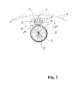
- Fig.2 shows in cross section a fan unit 9 in a slotted exhaust duct 5. At the tunnel ceiling 2 extending over the tunnel length track 3 for the movable fan unit 9 is arranged.
- the exhaust duct 5 is also arranged on the tunnel ceiling 2, with its holders 6 serve to fix it.
- the fan unit 9 on the track 3 is movable by the exhaust duct 5 has a slot 7 for the suspension 10 of the fan unit 9, wherein the slot 7 is closed by a seal, so that the exhaust duct 5 is closed
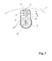
- the arrangement according to Fig. 3 also has a guideway 3 and an exhaust duct 5.
- the fan unit 9 on the guideway 3 can be moved, since the exhaust duct 5 includes the guideway 3.
- corresponding seals 22 are arranged on the circumference of the fan unit 9 and in the region of the suspension 10.
- the route 3 is encapsulated by a secondary channel 18 of the exhaust duct 5 by this includes the track 3 and the slot 7 opens into the secondary channel 18.
- the sealing of the exhaust duct 5 is achieved here by the fan unit 9 fills the exhaust duct 5.
- fan units 9 and jet engines as they are known from aircraft, can be used.
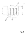
- Fig. 5 shows an embodiment of the intake ports 8 in the exhaust duct 5.
- the intake ports 8 of the exhaust duct 5 are closed by a sliding walls 14 of the exhaust duct 5.
- the exhaust duct 5 Since the exhaust duct 5 has no supporting function for the fan units 9 and only has to withstand the internal pressure generated by the fan units, it can be made comparatively thin-walled from a corrosion-resistant steel, preferably made of stainless steel.
- the wall 14 is arranged outside on the exhaust air duct 5.
- Figure 6 shows a further device for fire fighting by smoke evacuation in a tunneling 1.
- the tunnel ceiling 2 is an over the tunnel length extending track 3 for four interconnected jointly movable fan units 9, each with a own exhaust duct 5 is arranged.
- the exhaust air ducts 5 are likewise arranged on the tunnel ceiling 2 and have closable intake openings 8.
- the suspension 10 of the fan units 9 on the track 3 consists of a common chassis 19 with a support arm 20 or a support surface, wherein the chassis 19 is arranged independently movable on the track 3. On the support arm 20 or the support surface, the fan units 9 are arranged supported.
- the support 24 of the suspension 10 for the fan units 9 protrudes through a slot 7 of the exhaust duct 5 in this.
- the slot 7 is closed by a seal 21 which opens in the process of the fan units 9 only in the region of the respective support 24 and then closes again.
- the fan units 9 are arranged on both sides of the chassis 19 and symmetrically to the chassis 3, so that it is also possible to work with a monorail 3.
- the fan units 9 fill the exhaust air duct 5 enclosing them on the circumference or this takes place using the illustrated seal 22 arranged on the fan circumference.
- the chassis 19 has a drive source for the fans of the fan units 9 in the form of stored electrical energy and / or compressed air and is connected via corresponding supply lines to the fan units 9.
- the chassis 19 or an attachable to the chassis 19, movable on the track 3 unit also have a fluid tank, the content of which is conveyed under pressure via lines to spray units 13 in front of the fan units 9 to be blown into the flue gases in front of the fan blades 12.
- chassis 19 is equipped with means 23 for extinguishing fire or a device for extinguishing fire on the chassis 19 can be coupled.
- Figure 7 shows two interconnected jointly movable fan units 9 with a common exhaust duct 5.
- the fan units 9 are suspended on the track 3 movable, wherein the exhaust duct 5 includes the track 3.
- the exhaust duct 5 is brought up to the track 3. It would also be possible to connect directly to the tunnel ceiling 2.
- the suspension 10 also consists here of a chassis 19 with a support arm 20 or a support surface, wherein the chassis 19 is arranged independently movable on the track 3, and on the at least one support arm 20 or the wing, the fan units 9 are arranged.
- the chassis 19 is also included in the encapsulation by the exhaust air duct 5.
- Figure 8 shows an embodiment of the device according to the invention with four interconnected jointly movable fan units 9 arranged in two exhaust ducts 5.
- the track 3 here consists of two parallel rails on the tunnel ceiling. 2
- the suspension 10 also consists of a chassis 19 with a support arm 20 or a support surface, wherein the chassis 19 is arranged independently movable on the track 3.
- the fan units 9 are arranged here on both sides of the chassis 19 and symmetrically to the chassis 3.
- the fan units 9 are arranged supported on the support arm 20 or the support surface.
- the support 24 of the suspension 10 for the fan units 9 protrudes through a slot 7 of the exhaust duct 5 in this.
- the slot 7 is closed by a seal 21 which opens in the process of the fan units 9 only in the region of the respective support 24 and then closes again.
- the space between the fan units 9 and between the fan units 9 and the exhaust duct 5 is sealed by a closure plate 25 with at least openings for the fan units 9.
- the chassis 19 is also equipped here with means 23 for extinguishing fire or a device for extinguishing fire can be coupled to the chassis 19.
- Fig. 9 shows in a detail drawing a section through a railroad track 3.
- the track is fastened by means of brackets 4 to the tunnel ceiling 2.
- It is preferably a T or double T-profile, driven on the mecanical muscles 17 of the chassis 19 and thus move the fan units 9 to the fire.
Landscapes
- Engineering & Computer Science (AREA)
- Mining & Mineral Resources (AREA)
- Life Sciences & Earth Sciences (AREA)
- General Life Sciences & Earth Sciences (AREA)
- Geochemistry & Mineralogy (AREA)
- Geology (AREA)
- Mechanical Engineering (AREA)
- General Engineering & Computer Science (AREA)
- Ventilation (AREA)
Applications Claiming Priority (2)
| Application Number | Priority Date | Filing Date | Title |
|---|---|---|---|
| DE102013012054.3A DE102013012054A1 (de) | 2013-07-15 | 2013-07-15 | Verfahren und Vorrichtung zur Brandbekämpfung durch Rauchgasabsaugung |
| DE201320011180 DE202013011180U1 (de) | 2013-12-11 | 2013-12-11 | Vorrichtung zur Brandbekämpfung insbesondere durch Rauchgasabsaugung |
Publications (2)
| Publication Number | Publication Date |
|---|---|
| EP2826953A2 true EP2826953A2 (fr) | 2015-01-21 |
| EP2826953A3 EP2826953A3 (fr) | 2016-04-06 |
Family
ID=51212651
Family Applications (1)
| Application Number | Title | Priority Date | Filing Date |
|---|---|---|---|
| EP14075046.4A Withdrawn EP2826953A3 (fr) | 2013-07-15 | 2014-07-10 | Procédé et dispositif de lutte contre les incendies par aspiration des gaz de fumées |
Country Status (1)
| Country | Link |
|---|---|
| EP (1) | EP2826953A3 (fr) |
Cited By (6)
| Publication number | Priority date | Publication date | Assignee | Title |
|---|---|---|---|---|
| DE102015001958A1 (de) | 2015-02-09 | 2016-08-11 | Martin Kuhblank | Vorrichtung und Verfahren zum Absaugen von heißen Gasen aus Räumen |
| CN107725090A (zh) * | 2017-10-10 | 2018-02-23 | 上海市政工程设计研究总院(集团)有限公司 | 一种地下隧道通风系统及其实施方法 |
| CN110043303A (zh) * | 2019-03-26 | 2019-07-23 | 淮北矿业股份有限公司 | 一种岩巷综掘可移动式除尘风机 |
| CN111271111A (zh) * | 2020-04-01 | 2020-06-12 | 贵州省交通规划勘察设计研究院股份有限公司 | 一种可调整管口方向的机械式通风管及其使用方法 |
| IT201900020868A1 (it) * | 2019-11-12 | 2021-05-12 | Rosso Officine S R L | Sistema di estrazione forzata dei fumi in caso di incendio |
| CN118292928A (zh) * | 2024-05-23 | 2024-07-05 | 中铁建工集团有限公司 | 一种用于隧道事故紧急处理的隧道通风空气净化装置 |
Citations (6)
| Publication number | Priority date | Publication date | Assignee | Title |
|---|---|---|---|---|
| DE29911569U1 (de) | 1999-07-02 | 1999-09-30 | Heck, Jürgen, 53359 Rheinbach | Automatisches Brandschutzsystem für Verkehrstunnels |
| WO2002103163A1 (fr) | 2001-06-15 | 2002-12-27 | Thyssenkrupp Hiserv Gmbh | Dispositif d'aspiration conçu pour un tunnel |
| WO2004018050A1 (fr) | 2002-08-20 | 2004-03-04 | Roland Kuhblank | Installation d'extinction d'incendie et systeme de conduite pour tunnels et ouvrages similaires |
| EP1398461A1 (fr) | 2002-09-03 | 2004-03-17 | TLT-Turbo GmbH | Procédé et appareil pour l'aération d'un tunnel |
| EP1081331B1 (fr) | 1999-09-02 | 2004-08-11 | Rud. Otto Meyer GmbH & Co. KG | Procédé et système d'aspiration pour la ventilation, p.e. de fumée dans des tunnels |
| EP1399645B1 (fr) | 2001-06-05 | 2005-10-26 | HiServ Gebäudedienstleistungen GmbH | Dispositif d'aspiration avec systeme coupe-feu |
Family Cites Families (2)
| Publication number | Priority date | Publication date | Assignee | Title |
|---|---|---|---|---|
| FR2808215A1 (fr) * | 2000-04-18 | 2001-11-02 | Poinsard Brisson De Saint Aman | Application nouvelle permettant notamment dans les tunnels routiers, en cas d'incendie de positionner en quelques secondes, l'element extincteur en face du feu |
| DE10051285B4 (de) * | 2000-10-16 | 2004-05-13 | Carsten Bardehle | Stationäre Löschvorrichtung |
-
2014
- 2014-07-10 EP EP14075046.4A patent/EP2826953A3/fr not_active Withdrawn
Patent Citations (6)
| Publication number | Priority date | Publication date | Assignee | Title |
|---|---|---|---|---|
| DE29911569U1 (de) | 1999-07-02 | 1999-09-30 | Heck, Jürgen, 53359 Rheinbach | Automatisches Brandschutzsystem für Verkehrstunnels |
| EP1081331B1 (fr) | 1999-09-02 | 2004-08-11 | Rud. Otto Meyer GmbH & Co. KG | Procédé et système d'aspiration pour la ventilation, p.e. de fumée dans des tunnels |
| EP1399645B1 (fr) | 2001-06-05 | 2005-10-26 | HiServ Gebäudedienstleistungen GmbH | Dispositif d'aspiration avec systeme coupe-feu |
| WO2002103163A1 (fr) | 2001-06-15 | 2002-12-27 | Thyssenkrupp Hiserv Gmbh | Dispositif d'aspiration conçu pour un tunnel |
| WO2004018050A1 (fr) | 2002-08-20 | 2004-03-04 | Roland Kuhblank | Installation d'extinction d'incendie et systeme de conduite pour tunnels et ouvrages similaires |
| EP1398461A1 (fr) | 2002-09-03 | 2004-03-17 | TLT-Turbo GmbH | Procédé et appareil pour l'aération d'un tunnel |
Cited By (8)
| Publication number | Priority date | Publication date | Assignee | Title |
|---|---|---|---|---|
| DE102015001958A1 (de) | 2015-02-09 | 2016-08-11 | Martin Kuhblank | Vorrichtung und Verfahren zum Absaugen von heißen Gasen aus Räumen |
| CN107725090A (zh) * | 2017-10-10 | 2018-02-23 | 上海市政工程设计研究总院(集团)有限公司 | 一种地下隧道通风系统及其实施方法 |
| CN107725090B (zh) * | 2017-10-10 | 2024-04-05 | 上海市政工程设计研究总院(集团)有限公司 | 一种地下隧道通风系统及其实施方法 |
| CN110043303A (zh) * | 2019-03-26 | 2019-07-23 | 淮北矿业股份有限公司 | 一种岩巷综掘可移动式除尘风机 |
| CN110043303B (zh) * | 2019-03-26 | 2021-04-06 | 淮北矿业股份有限公司 | 一种岩巷综掘可移动式除尘风机 |
| IT201900020868A1 (it) * | 2019-11-12 | 2021-05-12 | Rosso Officine S R L | Sistema di estrazione forzata dei fumi in caso di incendio |
| CN111271111A (zh) * | 2020-04-01 | 2020-06-12 | 贵州省交通规划勘察设计研究院股份有限公司 | 一种可调整管口方向的机械式通风管及其使用方法 |
| CN118292928A (zh) * | 2024-05-23 | 2024-07-05 | 中铁建工集团有限公司 | 一种用于隧道事故紧急处理的隧道通风空气净化装置 |
Also Published As
| Publication number | Publication date |
|---|---|
| EP2826953A3 (fr) | 2016-04-06 |
Similar Documents
| Publication | Publication Date | Title |
|---|---|---|
| EP2826953A2 (fr) | Procédé et dispositif de lutte contre les incendies par aspiration des gaz de fumées | |
| DE19825420C2 (de) | Verfahren und Vorrichtung zur Rauchgas- und Wärmeabsaugung sowie zur Betriebslüftung für Verkehrsbauten und Räume | |
| DE2452526C2 (de) | Lufteinlaß für den Turboantrieb eines Luftfahrzeuges, insbesondere eines Hubschraubers | |
| DE69801762T2 (de) | Vorrichtung zur inspektion und zum reinigen von lüftungs- oder klimarohren, und andere rohrleitungen | |
| EP1931479B1 (fr) | Dispositif et procede destines a separer la peinture humide perdue lors de la pulverisation | |
| DE102010005552B4 (de) | Verfahren, Vorrichtung und Düse zum Löschen von Funken | |
| EP1312392B1 (fr) | Procédé et dispositif d'extinction d'incendies dans un tunnel | |
| EP1398461A1 (fr) | Procédé et appareil pour l'aération d'un tunnel | |
| EP1081331B1 (fr) | Procédé et système d'aspiration pour la ventilation, p.e. de fumée dans des tunnels | |
| DE69826507T2 (de) | Verfahren und system zur erleichterung von rettungs- und evakuierungsmassnahmen aus geschlossenen räumen | |
| DE19934118C2 (de) | Verfahren und Vorrichtung zum Löschen von Bränden in Tunneln | |
| DE102007029554B4 (de) | Absaugeinrichtung und unterirdischer Bahnhof mit einer solchen Absaugeinrichtung | |
| DE2946436C2 (de) | Sprühkabine | |
| DE3321195C2 (fr) | ||
| DE102013012054A1 (de) | Verfahren und Vorrichtung zur Brandbekämpfung durch Rauchgasabsaugung | |
| DE10231230B4 (de) | Wassersprühnebel-System zur Brandort-Lokalisierung | |
| DE202013011180U1 (de) | Vorrichtung zur Brandbekämpfung insbesondere durch Rauchgasabsaugung | |
| EP1166823A2 (fr) | Appareil d'insertion et méthode de déplacement de masses d'air contaminé | |
| EP1399645B1 (fr) | Dispositif d'aspiration avec systeme coupe-feu | |
| WO2001080954A1 (fr) | Agencement pour securiser l'evacuation et le sauvetage en cas de sollicitations dues a des fumees, des charges thermiques et polluantes | |
| WO2004005102A1 (fr) | Procede pour faire fonctionner la voie d'un vehicule guide sur rails, et une telle voie | |
| DE10262177B4 (de) | Verfahren zur Absaugung von Gasen im Brandfall | |
| DE102006013305B3 (de) | Feuerlöscheinrichtung zum Löschen definierter Objekte | |
| DE102015116310A1 (de) | Verfahren und Vorrichtung zur Medienentnahme zur Havariebekämpfung | |
| DE10009734A1 (de) | Verfahren und Absauganlage zum Entlüften bzw. Rauchgasabsaugen in einem Tunnel |
Legal Events
| Date | Code | Title | Description |
|---|---|---|---|
| 17P | Request for examination filed |
Effective date: 20140710 |
|
| AK | Designated contracting states |
Kind code of ref document: A2 Designated state(s): AL AT BE BG CH CY CZ DE DK EE ES FI FR GB GR HR HU IE IS IT LI LT LU LV MC MK MT NL NO PL PT RO RS SE SI SK SM TR |
|
| AX | Request for extension of the european patent |
Extension state: BA ME |
|
| PUAI | Public reference made under article 153(3) epc to a published international application that has entered the european phase |
Free format text: ORIGINAL CODE: 0009012 |
|
| PUAL | Search report despatched |
Free format text: ORIGINAL CODE: 0009013 |
|
| AK | Designated contracting states |
Kind code of ref document: A3 Designated state(s): AL AT BE BG CH CY CZ DE DK EE ES FI FR GB GR HR HU IE IS IT LI LT LU LV MC MK MT NL NO PL PT RO RS SE SI SK SM TR |
|
| AX | Request for extension of the european patent |
Extension state: BA ME |
|
| RIC1 | Information provided on ipc code assigned before grant |
Ipc: E21F 5/02 20060101ALI20160302BHEP Ipc: E21F 1/08 20060101ALI20160302BHEP Ipc: E21F 1/00 20060101AFI20160302BHEP |
|
| STAA | Information on the status of an ep patent application or granted ep patent |
Free format text: STATUS: THE APPLICATION IS DEEMED TO BE WITHDRAWN |
|
| 18D | Application deemed to be withdrawn |
Effective date: 20161007 |