EP2827317A1 - Dispositif permettant de déterminer la sensibilité à la prédiction de situations inattendues - Google Patents
Dispositif permettant de déterminer la sensibilité à la prédiction de situations inattendues Download PDFInfo
- Publication number
- EP2827317A1 EP2827317A1 EP13761346.9A EP13761346A EP2827317A1 EP 2827317 A1 EP2827317 A1 EP 2827317A1 EP 13761346 A EP13761346 A EP 13761346A EP 2827317 A1 EP2827317 A1 EP 2827317A1
- Authority
- EP
- European Patent Office
- Prior art keywords
- intersection
- vehicle
- driving operation
- travel information
- operation level
- Prior art date
- Legal status (The legal status is an assumption and is not a legal conclusion. Google has not performed a legal analysis and makes no representation as to the accuracy of the status listed.)
- Granted
Links
Images





Classifications
-
- G—PHYSICS
- G08—SIGNALLING
- G08G—TRAFFIC CONTROL SYSTEMS
- G08G1/00—Traffic control systems for road vehicles
- G08G1/01—Detecting movement of traffic to be counted or controlled
- G08G1/0104—Measuring and analyzing of parameters relative to traffic conditions
- G08G1/0108—Measuring and analyzing of parameters relative to traffic conditions based on the source of data
- G08G1/0112—Measuring and analyzing of parameters relative to traffic conditions based on the source of data from the vehicle, e.g. floating car data [FCD]
-
- G—PHYSICS
- G08—SIGNALLING
- G08G—TRAFFIC CONTROL SYSTEMS
- G08G1/00—Traffic control systems for road vehicles
- G08G1/01—Detecting movement of traffic to be counted or controlled
- G08G1/0104—Measuring and analyzing of parameters relative to traffic conditions
- G08G1/0125—Traffic data processing
- G08G1/0129—Traffic data processing for creating historical data or processing based on historical data
-
- G—PHYSICS
- G08—SIGNALLING
- G08G—TRAFFIC CONTROL SYSTEMS
- G08G1/00—Traffic control systems for road vehicles
- G08G1/16—Anti-collision systems
- G08G1/161—Decentralised systems, e.g. inter-vehicle communication
- G08G1/163—Decentralised systems, e.g. inter-vehicle communication involving continuous checking
-
- G—PHYSICS
- G08—SIGNALLING
- G08G—TRAFFIC CONTROL SYSTEMS
- G08G1/00—Traffic control systems for road vehicles
- G08G1/16—Anti-collision systems
- G08G1/164—Centralised systems, e.g. external to vehicles
Definitions
- the present invention relates to an unexpectedness prediction sensitivity determination apparatus.
- a vehicle collects vehicle velocity information. Subsequently, the vehicle transmits the collected vehicle velocity information to a base station. Subsequently, the base station records the received vehicle velocity information. Subsequently, the base station determines an unexpectedness prediction sensitivity of a driver based on the entire recorded vehicle velocity information.
- the unexpectedness prediction sensitivity refers to an index indicating a degree of capacity of predicting unexpected situations in which the vehicle approaches an obstacle such as another vehicle or a pedestrian (caused since the vehicle approaches an oncoming vehicle that travels straight on the opposite lane when the vehicle turns to the right or left at an intersection, caused since the vehicle approaches a motorcycle that travels on the left side when the vehicle turns to the left at an intersection, caused since the vehicle approaches a pedestrian when the vehicle turns to the right or left at an intersection, or the like), for example.
- an obstacle such as another vehicle or a pedestrian
- the unexpectedness prediction sensitivity of the driver is determined simply based on the entire recorded vehicle velocity information.
- the vehicle velocity when turning to the right or left at the intersection varies, there is a possibility that determination accuracy of the unexpectedness prediction sensitivity of the driver when turning to the right or left at the intersection deteriorates.
- the invention is made in order to solve the above problem, and an object thereof is to improve determination accuracy of an unexpectedness prediction sensitivity of a driver when turning to the right or left at an intersection.
- a standard driving operation level of a driver when turning to the right or left at an intersection is determined for each intersection based on intersection travel information received from plural vehicles. Subsequently, in this aspect of the invention, the unexpectedness prediction sensitivity of the driver when turning to the right or left at the intersection is determined based on the intersection travel information associated with the intersections where determined standard driving operation levels of the drivers are identical to one another.
- the aspect of the invention for example, even when the standard driving operation level of the driver when turning to the right or left at the intersection for each intersection is changed according to visibility or a traffic volume of the intersection, a driving operation of the driver when turning to the right or left at the intersection is changed, and a travel state amount included in the intersection travel information when turning to the right or left at the intersection varies for each intersection, it is possible to reduce the variation of the travel state amount used for determination of the unexpectedness prediction sensitivity of the driver.
- the invention is applied to an unexpectedness prediction sensitivity determination system S.
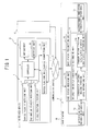
- FIG. 1 is a diagram schematically illustrating a configuration of an unexpectedness prediction sensitivity determination system S.
- the unexpectedness prediction sensitivity determination system S includes an in-vehicle device 1 that is mounted in each of plural vehicles C and an unexpectedness prediction sensitivity determination apparatus 2 provided in a base station B.
- the in-vehicle device 1 and the unexpectedness prediction sensitivity determination apparatus 2 transmit and receive information through a communication channel 3.
- the in-vehicle device 1 includes a vehicle velocity detecting unit 4, a yaw angular velocity detecting unit 5, a vehicle position detecting unit 6, a map database 7, a vehicle receiving unit 8, a controller 9, a notifying unit 10 and a vehicle transmitting unit 11.
- the vehicle velocity detecting unit 4 detects a current vehicle velocity V of the vehicle C. Further, the vehicle velocity detecting unit 4 outputs information indicating the detected current vehicle velocity V to the controller 9.
- the vehicle velocity detecting unit 4 for example, a vehicle velocity sensor that detects a vehicle velocity V based on a rotational speed of a wheel of the vehicle C is employed.
- the yaw angular velocity detecting unit 5 detects a current yaw angular velocity ⁇ of the vehicle C. Further, the yaw angular velocity detecting unit 5 outputs information indicating the detected current yaw angular velocity ⁇ to the controller 9. As the yaw angular velocity detecting unit 5, for example, a yaw angular velocity sensor is employed.
- the vehicle position detecting unit 6 detects a current position of the vehicle C. Further, the vehicle position detecting unit 6 outputs information indicating the detected current position to the controller 9. As the vehicle position detecting unit 6, for example, a global positioning system (GPS) receiver is employed.
- GPS global positioning system
- the map database 7 records therein map information about an area where the vehicle C is traveling.
- the map information includes information about the position, shape, type and the like of a road or an intersection.
- the intersection includes an intersection where a traffic signal is present and an intersection where the traffic signal is not present.
- the vehicle receiving unit 8 receives information transmitted by the unexpectedness prediction sensitivity determination apparatus 2 through the communication channel 3. Further, the vehicle receiving unit 8 outputs the received information to the controller 9.
- FIGS. 2A to 2C are diagrams illustrating an intersection passage characteristic value.
- the controller 9 executes an intersection travel information transmission process based on the information output by the vehicle velocity detecting unit 4, the yaw angular velocity detecting unit 5 and the vehicle position detecting unit 6 and the map information recorded in the map database 7.
- the controller 9 generates intersection travel information every time the vehicle C turns to the right or left at the intersection.
- the intersection travel information refers to data that includes an intersection passage characteristic value when turning to the right or left at the intersection, an intersection ID of the intersection where the corresponding intersection passage characteristic value is obtained and a vehicle ID of the vehicle C.
- the intersection ID refers to unique information set for each intersection, which may uniquely specify the intersection.
- intersection ID a numerical number of 1 to n (n is the total number of intersections registered in map data) may be employed.
- the vehicle ID refers to unique information set for each vehicle C mounted with the in-vehicle device 1, which may uniquely specify the vehicle C.
- a numerical number of 1 to m m is the total number of vehicles C mounted with the in-vehicle device 1.
- the intersection passage characteristic value refers to a travel state amount indicating a travel state of the vehicle C when turning to the right or left at the intersection, which is an index value indicating a standard driving operation level of a driver when turning to the right or left at the intersection (to be described later) and an unexpectedness prediction sensitivity of the driver.
- a travel state amount indicating a travel state of the vehicle C when turning to the right or left at the intersection
- an index value indicating a standard driving operation level of a driver when turning to the right or left at the intersection (to be described later) and an unexpectedness prediction sensitivity of the driver.
- a maximum value of the yaw angular velocity ⁇ when turning to the right or left at the intersection (hereinafter, also referred to as a maximum yaw angular velocity ⁇ max) and a vehicle velocity when the yaw angular velocity ⁇ reaches the maximum value when turning to the right or left at the intersection (hereinafter, also referred to as a yaw angular velocity maximum vehicle velocity Vymax) are employed.
- the controller 9 transmits the generated intersection travel information to the unexpectedness prediction sensitivity determination apparatus 2 through the vehicle transmitting unit 11.
- a transverse acceleration maximum vehicle velocity that is a vehicle velocity when a transverse acceleration reaches the maximum value when turning to the right or left at the intersection may be employed instead of the yaw angular velocity maximum vehicle velocity Vymax.
- controller 9 outputs a notification command for notifying the determination result of the unexpectedness prediction sensitivity of the driver of the vehicle C based on the information output by the vehicle receiving unit 8, to the notifying unit 10.
- the notifying unit 10 notifies the determination result of the unexpectedness prediction sensitivity of the driver of the vehicle C based on the notification command output by the controller 9.
- the notifying unit 10 for example, a monitor or a speaker is employed.
- the vehicle transmitting unit 11 transmits the intersection travel information generated by the controller 9 to the unexpectedness prediction sensitivity determination apparatus 2 through the communication channel 3.
- the unexpectedness prediction sensitivity determination apparatus 2 includes a base station receiving unit 12, an intersection travel information recording unit 13, an intersection driver characteristic determining unit 14, an unexpectedness prediction sensitivity determining unit 15, and a base station transmitting unit 16.
- the base station receiving unit 12 receives the intersection travel information transmitted by the vehicle transmitting unit 11 through the communication channel 3. Further, the vehicle receiving unit 8 outputs the received intersection travel information to the intersection travel information recording unit 13.
- the intersection travel information recording unit 13 records therein the intersection travel information about the plural vehicles C based on the intersection travel information received by the base station receiving unit 12.
- a hard disk drive (HDD) or a random access memory (RAM) is employed as the intersection travel information recording unit 13, for example.
- the intersection driver characteristic determining unit 14 includes an intersection standard driving operation level determining unit 14a and a standard driving operation level-separated driver characteristic determining unit 14b.
- the intersection standard driving operation level determining unit 14a calculates an average value ⁇ maxAve (hereinafter, also referred to as an intersection passage characteristic value average) of an absolute value of the intersection passage characteristic value ⁇ max for each intersection based on the intersection travel information received from the plural vehicles C, among the intersection travel information recorded in the intersection travel information recording unit 13. As the intersection travel information received from the plural vehicles C, for example, the intersection travel information received from all the vehicles C that turn to the right or left at the target intersection is employed. Subsequently, the intersection standard driving operation level determining unit 14a determines the standard driving operation level of the driver when turning to the right or left at the intersection for each intersection based on the calculated intersection passage characteristic value average ⁇ maxAve.
- an intersection passage characteristic value average hereinafter, also referred to as an intersection passage characteristic value average
- the standard driving operation level of the driver when turning to the right or left at the intersection for example, an index of the level of a driving operation of a standard driver when turning to the right or left at the intersection is used.
- the predetermined plural stages for example, two stages of "high” and "low” are employed.
- the standard driving operation level-separated driver characteristic determining unit 14b selects the intersection travel information associated with the intersections where the standard driving operation levels of the drivers determined by the intersection standard driving operation level determining unit 14a are identical to one another, among the intersection travel information recorded in the intersection travel information recording unit 13.
- the intersection travel information associated with the intersections where the standard driving operation level of the driver is at the highest stage "high" is employed.
- the standard driving operation level-separated driver characteristic determining unit 14b calculates an average value (hereinafter, also referred to as a vehicle-separated intersection passage characteristic value average) V ⁇ maxCAve of the intersection passage characteristic value Vymax for each vehicle C based on the selected intersection travel information.
- an average value hereinafter, also referred to as a vehicle-separated intersection passage characteristic value average
- V ⁇ maxCAve of the intersection passage characteristic value Vymax for each vehicle C based on the selected intersection travel information.
- the unexpectedness prediction sensitivity determining unit 15 determines the unexpectedness prediction sensitivity of the driver when turning to the right or left at the intersection for each vehicle C based on the vehicle-separated intersection passage characteristic value average V ⁇ maxCAve calculated by the standard driving operation level-separated driver characteristic determining unit 14b.
- the unexpectedness prediction sensitivity of the driver when turning to the right or left at the intersection refers to an index value indicating a possibility that the vehicle is approaching another vehicle or a pedestrian when turning to the right or left at the intersection.
- the predetermined plural stages for example, three stages of "high", “intermediate” and "low” are employed.
- the base station transmitting unit 16 transmits the unexpectedness prediction sensitivity of the driver determined by the unexpectedness prediction sensitivity determining unit 15 to the vehicle receiving unit 8 provided in each of the plural vehicles C through the communication channel 3.
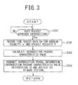
- FIG. 3 is a flowchart illustrating the intersection travel information transmission process.
- step S101 the controller 9 determines whether or not the vehicle C approaches the intersection based on the current position of the vehicle C detected by the vehicle position detecting unit 6 and the map data recorded in the map database 7. Specifically, the controller 9 determines whether or not the vehicle C is within a predetermined set range of the intersection (for example, within a range of a radius of 30m from the center of the intersection). Then, if it is determined that the vehicle C is within the set range of the intersection (Yes), the controller 9 determines that the vehicle C approaches the intersection, and the procedure proceeds to step S102. On the other hand, if it is determined that the vehicle C is out of the set range of the intersection (No), the controller 9 determines that the vehicle C does not approach the intersection, and the determination in step S101 is executed again.
- a predetermined set range of the intersection for example, within a range of a radius of 30m from the center of the intersection.
- step S102 the controller 9 records time series data on the yaw angular velocity ⁇ and time series data on the vehicle velocity V when turning to the right or left at the intersection (hereinafter, also referred to as a target intersection) that is determined as being approached by the vehicle C in step S101. Specifically, first, the controller 9 starts the recording of the time series data on the yaw angular velocity ⁇ and the time series data on the vehicle velocity V. A sampling time of the time series data is set to 10 [msec], for example. Subsequently, the controller 9 determines whether or not the vehicle C turns to the right or left at the target intersection based on the current position of the vehicle C detected by the vehicle position detecting unit 6 and the map data stored in the map database 7.
- the controller 9 determines whether or not a road that the vehicle C travels after passage of the target intersection (that is, after getting out of the set range) is a road (hereinafter, referred to as an intersection road) that intersects with a road that the vehicle C has traveled before passage of the target intersection. Further, if it is determined that the road that the vehicle C travels after passage of the target intersection is the intersection road (Yes), the controller 9 determines that the vehicle C turns to the right or left at the target intersection, and the procedure proceeds to step S106.
- an intersection road a road that the vehicle C travels after passage of the target intersection
- the controller 9 determines that the vehicle C does not turn to the right or left at the target intersection, and the procedure returns to step S101. If the procedure returns to step S101, the controller 9 deletes the recorded time series data on the yaw angular velocity ⁇ and the vehicle velocity V.
- step S103 the controller 9 calculates the intersection passage characteristic values (maximum yaw angular velocity and yaw angular velocity maximum vehicle velocity) ⁇ max and Vymax based on the time series data on the yaw angular velocity ⁇ and the time series data on the vehicle velocity V recorded in step S102. Specifically, the controller 9 sets the vehicle velocity V when the yaw angular velocity ⁇ reaches the maximum value ⁇ max when turning to the right or left at the intersection as the yaw angular velocity maximum vehicle velocity Vymax based on the time series data on the yaw angular velocity ⁇ and the time series data on the vehicle velocity V. Subsequently, the controller 9 generates intersection travel information including the calculated intersection passage characteristic values ⁇ max and V ⁇ max, an intersection ID of the target intersection and a vehicle ID of the vehicle C.
- step S104 the controller 9 transmits the intersection travel information generated in step S103 to the base station B through the vehicle transmitting unit 11.
- the unexpectedness prediction sensitivity determination apparatus 2 (the base receiving unit 12, the intersection travel information recording unit 13, the intersection driver characteristic determining unit 14, the unexpectedness prediction sensitivity determining unit 15 and the base station transmitting unit 16) will be described.
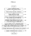
- FIG. 4 is a flowchart illustrating the unexpectedness prediction sensitivity determination process.
- step S201 the base station receiving unit 12 receives the intersection travel information (the data including the intersection passage characteristic value, the intersection ID of the target intersection and the vehicle ID of the vehicle C) transmitted by the in-vehicle device 1.
- the intersection travel information the data including the intersection passage characteristic value, the intersection ID of the target intersection and the vehicle ID of the vehicle C
- the procedure proceeds to step S202, and then, the intersection travel information recording unit 13 records the intersection travel information received in step S201.
- the intersection travel information recording unit 13 records the intersection travel information of the plural vehicles C at plural intersections.
- the procedure proceeds to step S203, and then, the intersection standard driving operation level determining unit 14a extracts the intersection travel information recorded in a predetermined set period (for example, a period of 30 days prior to the current date) from among the intersection travel information recorded in the intersection travel information recording unit 13.
- a predetermined set period for example, a period of 30 days prior to the current date
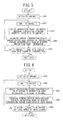
- FIG. 5 is a flowchart illustrating details of the process executed in step S204.
- the procedure proceeds to step S204, and then, the intersection standard driving operation level determining unit 14a calculates the average value (intersection passage characteristic value average) ⁇ maxAve of the absolute value of the intersection passage characteristic value (maximum yaw angular velocity) ⁇ max for each intersection based on the intersection travel information received from the plural vehicles C (that is, all the vehicles C) among the intersection travel information extracted in step S203. Specifically, as shown in FIG. 5 , first, the intersection standard driving operation level determining unit 14a initializes a variable i to 0 (step S301). Subsequently, the intersection standard driving operation level determining unit 14a adds 1 to the variable i (step S302).
- the intersection standard driving operation level determining unit 14a selects the intersection travel information including the intersection ID having a numerical value equal to the variable i from among the extracted intersection travel information (step S303). Subsequently, the intersection standard driving operation level determining unit 14a sets the average value (intersection passage characteristic value average) ⁇ maxAve of the absolute value of the intersection passage characteristic value ⁇ max included in the selected intersection travel information as an average value of the intersection passage characteristic value of the intersection whose intersection ID is equal to the variable i (step S304). Further, the intersection standard driving operation level determining unit 14a repeats the flow (steps S302 to S304) until the variable i becomes equal to or greater than the total number n of the intersections (step S305). Thus, the intersection standard driving operation level determining unit 14a calculates the intersection passage characteristic value average ⁇ maxAve with respect to all the intersections.
- FIG. 6 is a flowchart illustrating details of the process executed in step S205.
- FIG. 7 is a diagram illustrating the relationship between the intersection passage characteristic value average and the standard driving operation level of the driver.
- the procedure proceeds to step S205, and then, the intersection standard driving operation level determining unit 14a determines the standard driving operation level of the driver when turning to the right or left at the intersection for each intersection based on the intersection passage characteristic value average ⁇ maxAve calculated in step S204. Specifically, the intersection standard driving operation level determining unit 14a initializes a variable j to 0, as shown in FIG. 6 (step S401). Subsequently, the intersection standard driving operation level determining unit 14a adds 1 to the variable j (step S402).
- the intersection standard driving operation level determining unit 14a selects, from among the calculated intersection passage characteristic value average ⁇ maxAve, the intersection passage characteristic value average ⁇ maxAve corresponding to the intersection whose intersection ID is equal to the variable j (step S403). Subsequently, the intersection standard driving operation level determining unit 14a determines the standard driving operation level of the driver when turning to the right or left at the intersection whose intersection ID is equal to the variable j, based on the selected intersection passage characteristic value average ⁇ maxAve. Specifically, as shown in FIG.
- the intersection standard driving operation level determining unit 14a determines that the standard driving operation level of the driver when turning to the right or left at the intersection whose intersection ID is equal to the variable j is "low". On the other hand, if the selected intersection passage characteristic value average ⁇ maxAve is equal to or greater than 20 (deg/s), the intersection standard driving operation level determining unit 14a determines that the standard driving operation level of the driver when turning to the right or left at the intersection whose the intersection ID is equal to the variable j is "high" (step S404).
- the intersection standard driving operation level determining unit 14a determines that as the intersection passage characteristic value average ⁇ maxAve is larger, the standard driving operation level of the driver when turning to the right or left at the intersection is higher. That is, at the intersection where the radius of curvature of a path when turning to the right or left is small and the visibility is poor, the absolute value of the yaw angular velocity ⁇ becomes a relatively large value. Accordingly, if the intersection passage characteristic value average ⁇ maxAve is a large value, it is determined that the standard driving operation level of the driver when turning to the right or left at the intersection is "high".
- the intersection standard driving operation level determining unit 14a determines the standard driving operation level of the driver when turning to the right or left at the intersection with respect to all the intersections.
- FIG. 8 is a flowchart illustrating details of the process executed in step S206.
- the procedure proceeds to step S206, and then, as shown in FIG. 8 , the standard driving operation level-separated driver characteristic determining unit 14b selects the intersection travel information associated with the intersection where the standard driving operation level of the driver determined in step S205 is "high", from among the intersection travel information extracted in step S203 (step S501). Subsequently, the standard driving operation level-separated driver characteristic determining unit 14b calculates the average value (vehicle-separated intersection passage characteristic value average) V ⁇ maxCAve of the intersection passage characteristic value (yaw angular velocity maximum vehicle velocity) Vymax for each vehicle C based on the selected intersection travel information.
- the standard driving operation level-separated driver characteristic determining unit 14b initializes a variable k to 0 (step S502). Subsequently, the standard driving operation level-separated driver characteristic determining unit 14b adds 1 to the variable k (step S503). Subsequently, the standard driving operation level-separated driver characteristic determining unit 14b selects the intersection travel information associated with the vehicle ID having a numerical value equal to the variable k from among the intersection travel information selected in step S501 (step S504).
- the standard driving operation level-separated driver characteristic determining unit 14b sets the average value of the intersection passage characteristic value Vymax included in the selected intersection travel information as the average value (vehicle-separated intersection passage characteristic value average) V ⁇ maxCAve of the intersection passage characteristic value of the vehicle C whose vehicle ID is equal to the variable k (step S505). Further, the standard driving operation level-separated driver characteristic determining unit 14b repeats the flow (step S503 to S505) until the variable k becomes equal to or greater than the total number m of the vehicles (step S506). Thus, the standard driving operation level-separated driver characteristic determining unit 14b calculates the vehicle-separated intersection passage characteristic value average V ⁇ maxCAve with respect to all the vehicles C.
- FIG. 9 is a flowchart illustrating details of the process executed in step S207.
- the procedure proceeds to step S207, and then, the unexpectedness prediction sensitivity determining unit 15 determines the unexpectedness prediction sensitivity of the driver when turning to the right or left at the intersection for each vehicle C based on the intersection travel information extracted in step S203 and the standard driving operation level of the driver determined in step S205. Specifically, as shown in FIG. 9 , the unexpectedness prediction sensitivity determining unit 15 selects the intersection travel information associated with the intersection where the standard driving operation level of the driver determined in step S205 is "high" from among the intersection travel information extracted in step S203 (step S601).
- the unexpectedness prediction sensitivity determining unit 15 calculates an average value (hereinafter, also referred to as an all vehicle intersection passage characteristic value average) Vymaxth of the intersection passage characteristic value Vymax included in the selected intersection travel information and a standard deviation (hereinafter, referred to as an unexpectedness prediction sensitivity determination threshold value) ⁇ th of the intersection passage characteristic value Vymax (step S602). Subsequently, the unexpectedness prediction sensitivity determining unit 15 determines the unexpectedness prediction sensitivity of the driver when turning to the right or left at the intersection for each vehicle C based on a difference between the calculated all vehicle intersection passage characteristic value average V ⁇ maxth and the vehicle-separated intersection passage characteristic value average V ⁇ maxCAve calculated in step S206.
- an average value hereinafter, also referred to as an all vehicle intersection passage characteristic value average
- Vymaxth of the intersection passage characteristic value Vymax included in the selected intersection travel information
- a standard deviation hereinafter, referred to as an unexpectedness prediction sensitivity determination threshold value
- the unexpectedness prediction sensitivity determining unit 15 initializes a variable 1 to 0 (step S603). Subsequently, the unexpectedness prediction sensitivity determining unit 15 adds 1 to the variable 1 (step S604). Subsequently, the unexpectedness prediction sensitivity determining unit 15 selects the vehicle-separated intersection passage characteristic value average V ⁇ maxCAve of the vehicle C whose vehicle ID is equal to the variable 1 from among the calculated vehicle-separated intersection passage characteristic value average V ⁇ maxCAve (step S605).
- FIG. 10 is a diagram illustrating the relationship between the vehicle-separated intersection passage characteristic value average and the unexpectedness prediction sensitivity.
- the unexpectedness prediction sensitivity determining unit 15 determines the unexpectedness prediction sensitivity of the driver of the vehicle C whose vehicle ID is equal to the variable 1 when turning to the right or left at the intersection based on a subtraction result obtained by subtracting the all vehicle intersection passage characteristic value average Vth from the selected vehicle-separated intersection passage characteristic value average V ⁇ maxCAve (step S606). Specifically, as shown in FIG. 10 , if the subtraction result is equal to or greater than the unexpectedness prediction sensitivity determination threshold value ⁇ th, the unexpectedness prediction sensitivity determining unit 15 determines that the unexpectedness prediction sensitivity of the driver of the vehicle C whose vehicle ID is equal to the variable 1 when turning to the right or left at the intersection is "low".
- the unexpectedness prediction sensitivity determining unit 15 determines that the unexpectedness prediction sensitivity of the driver of the vehicle C whose vehicle ID is equal to the variable 1 when turning to the right or left at the intersection is "intermediate".
- the sign-inverted threshold value (- ⁇ th) represents a numerical value obtained by multiplying the unexpectedness prediction sensitivity determination threshold value ⁇ th by "-1".
- the unexpectedness prediction sensitivity determining unit 15 determines that the unexpectedness prediction sensitivity of the driver of the vehicle C whose vehicle ID is equal to the variable 1 when turning to the right or left at the intersection is "high" (step S606). Thus, the unexpectedness prediction sensitivity determining unit 15 determines that as the subtraction result (V ⁇ maxCAve-Vth) is smaller, the unexpectedness prediction sensitivity of the driver when turning to the right or left at the intersection is higher.
- the vehicle C having a large average value of the yaw angular velocity maximum vehicle velocity Vymax when turning to the right or left at the intersection has a high possibility of approaching another vehicle or a pedestrian when turning to the right or left at the intersection. Accordingly, if the subtraction result (V ⁇ maxCAve-Vth) is a large value, it is determined that the unexpectedness prediction sensitivity of the driver when turning to the right or left at the intersection is "low". On the other hand, the vehicle C having a small average value of the yaw angular velocity maximum vehicle velocity Vymax when turning to the right or left at the intersection has a low possibility of approaching another vehicle or a pedestrian when turning to the right or left at the intersection.
- the unexpectedness prediction sensitivity determining unit 15 repeats the flow (step S604 to S606) until the variable 1 becomes equal to or greater than the total number m of the vehicles (step S607).
- the unexpectedness prediction sensitivity determining unit 15 determines the unexpectedness prediction sensitivity of the driver when turning to the right or left at the intersection with respect to all the vehicles C.
- step S208 the unexpectedness prediction sensitivity determining unit 15 transmits the determination result of the unexpectedness prediction sensitivity performed in step S207 to the vehicle C specified by the vehicle ID of the intersection travel information received in step S201 through the base station transmitting unit 16.
- the determination result of the unexpectedness prediction sensitivity of the driver when turning to the right or left at the intersection is transmitted to the vehicle C
- a different configuration may be employed.
- a configuration in which the determination result of the unexpectedness prediction sensitivity of the driver when turning to the right or left at the intersection is used for setting of automobile insurance (for example, setting of grades) may be used.
- the determination result of the unexpectedness prediction sensitivity of the driver when turning to the right or left at the intersection may be transmitted to an insurance company or the like that handles automobile insurance through the communication channel 3.
- the controller 9 of the vehicle C1 records time series data on the yaw angular velocity ⁇ and the vehicle velocity V (steps S101 and S102 in FIG. 3 ).
- the controller 9 calculates the intersection passage characteristic values (maximum yaw angular velocity and yaw angular velocity maximum vehicle velocity) ⁇ max and Vymax based on the recorded time series data on the yaw angular velocity ⁇ and the vehicle velocity V. Subsequently, the controller 9 generates intersection travel information based on the calculated intersection passage characteristic values ⁇ max and Vymax (step S103 in FIG. 3 ). Further, the controller 9 transmits the generated intersection travel information to the base station B through the vehicle transmitting unit 11 (step S104 in FIG. 3 ).
- the unexpectedness prediction sensitivity determination apparatus 2 of the base station B receives the intersection travel information output by the controller 9 and records the received intersection travel information (by the base station receiving unit 12 and the intersection travel information recording unit 13 in FIG. 1 ) (steps S201 and S202 in FIG. 4 ). Subsequently, the unexpectedness prediction sensitivity determination apparatus 2 calculates the average value (intersection passage characteristic value average) ⁇ maxAve of the absolute value of the intersection passage characteristic value for each intersection based on the intersection travel information received from the plural vehicles C among the intersection travel information recorded in the intersection travel information recording unit 13 (by the intersection standard driving operation level determining unit 14a in FIG. 1 ) (steps S203 and S204 in FIG. 4 ).
- the unexpectedness prediction sensitivity determination apparatus 2 determines the standard driving operation level of the driver when turning to the right or left at the intersection for each intersection based on the calculated intersection passage characteristic value average ⁇ maxAve (by the intersection standard driving operation level determining section 14a in FIG. 1 ) (step S205 in FIG. 4 ).
- the unexpectedness prediction sensitivity determination apparatus 2 determines that the standard driving operation level of the driver when turning to the right or left at the intersection is "low” at an intersection where the intersection passage characteristic value average ⁇ maxAve satisfies 0 ⁇ maxAve ⁇ 20. Further, the unexpectedness prediction sensitivity determination apparatus 2 determines that the standard driving operation level of the driver when turning to the right or left at the intersection is "high” at an intersection where the intersection passage characteristic value average ⁇ maxAve satisfies 20 ⁇ maxAve.
- the unexpectedness prediction sensitivity determination apparatus 2 selects the intersection travel information associated with the intersection where the standard driving operation level of the driver is "high”. Subsequently, the unexpectedness prediction sensitivity determination apparatus 2 calculates the average value (vehicle-separated intersection passage characteristic value average) V ⁇ maxCAve of the intersection passage characteristic value Vymax for each vehicle C based on the selected intersection travel information (by the standard driving operation level-separated driver characteristic determining unit 14b in FIG. 1 ) (step S206 in FIG. 4 ).
- the unexpectedness prediction sensitivity determination apparatus 2 determines the unexpectedness prediction sensitivity of the driver when turning to the right or left at the intersection for each vehicle C based on the calculated vehicle-separated intersection passage characteristic value average V ⁇ maxCAve (by the unexpectedness prediction sensitivity determining unit 15 in FIG. 1 ) (step S207 in FIG. 4 ).
- the unexpectedness prediction sensitivity determination apparatus 2 determines the unexpectedness prediction sensitivity of the driver when turning to the right or left at the intersection for each vehicle C based on the calculated vehicle-separated intersection passage characteristic value average V ⁇ maxCAve (by the unexpectedness prediction sensitivity determining unit 15 in FIG. 1 ) (step S207 in FIG. 4 ).
- the unexpectedness prediction sensitivity determination apparatus 2 determines that the unexpectedness prediction sensitivity of the driver when turning to the right or left at the intersection is "low”. Further, with respect to the vehicle C in which the subtraction result (V ⁇ maxCAve-Vth) satisfies - ⁇ th ⁇ V ⁇ maxCAve-Vth ⁇ th, the unexpectedness prediction sensitivity determination apparatus 2 determines that the unexpectedness prediction sensitivity of the driver when turning to the right or left at the intersection is "intermediate".
- the unexpectedness prediction sensitivity determination apparatus 2 determines that the unexpectedness prediction sensitivity of the driver when turning to the right or left at the intersection is "high".
- the unexpectedness prediction sensitivity determination apparatus 2 transmits the determination result of the unexpectedness prediction sensitivity to the vehicle C1 through the base station transmitting unit 16 (by the unexpectedness prediction sensitivity determining unit 15 in FIG. 1 ) (step S208 in FIG. 4 ) .
- the controller 9 of the vehicle C1 receives the determination result output by the unexpectedness prediction sensitivity determination apparatus 2 through the vehicle receiving unit 8, and outputs a notification command to the notifying unit 10.
- the notifying unit 10 notifies the determination result of the unexpectedness prediction sensitivity of the driver when turning to the right or left at the intersection according to the notification command.
- the unexpectedness prediction sensitivity determination apparatus 2 of the present embodiment determines the unexpectedness prediction sensitivity of the driver when turning to the right or left at the intersection based on the intersection travel information associated with the intersection where the standard driving operation level of the driver when turning to the right or left at the intersection is "high", that is, the intersection where the radius of curvature of the path when turning to the right or left is small. Accordingly, in the unexpectedness prediction sensitivity determination apparatus 2 of the present embodiment, it is possible to delete the intersection travel information associated with the intersection where the radius of curvature of the path when turning to the right or left is large, from the intersection travel information used for determination of the unexpectedness prediction sensitivity of the driver.
- the unexpectedness prediction sensitivity determination apparatus 2 of the present embodiment it is possible to suppress the unexpectedness prediction sensitivity of the driver when turning to the right or left at the intersection from being mistakenly determined as "low” even though the frequency of passing the intersection where the radius of curvature of the path when turning to the right or left is large is high.
- the intersection passage characteristic values ⁇ max and Vymax form a travel state amount.
- the base station receiving unit 12 in FIG. 1 and step S201 in FIG. 4 form a receiving unit.
- the intersection travel information recording unit 13 in FIG. 1 and step S202 in FIG. 4 form an intersection travel information recording unit.
- the intersection standard driving operation level determining unit 14a in FIG. 1 and steps S204 and S205 in FIG. 4 form a standard driving operation level determining unit.
- the standard driving operation level-separated driver characteristic determining unit 14b in FIG. 1 the unexpectedness prediction sensitivity determining unit 15 and steps S206 and S207 in FIG. 4 form an unexpectedness prediction sensitivity determining unit.
- the vehicle-separated intersection passage characteristic value average V ⁇ maxCAve forms a vehicle-separated travel state average value.
- the intersection standard driving operation level determining unit 14a in FIG. 1 and step S204 in FIG. 4 form an average value calculating unit.
- the intersection standard driving operation level determining unit 14a in FIG. 1 and step S205 in FIG. 4 form a standard driving operation level determination executing unit.
- the standard driving operation level-separated driver characteristic determining unit 14b in FIG. 1 and step S206 in FIG. 4 form a vehicle-separated travel state average value calculating unit.
- the all vehicle intersection passage characteristic value average Vth forms a plural-vehicle travel state average value.
- the unexpectedness prediction sensitivity determining unit 15 in FIG. 1 and step S207 in FIG. 4 form a plural-vehicle travel state average value calculating unit and an unexpectedness prediction sensitivity determination executing unit.
- the present embodiment shows the following effects.
- the unexpectedness prediction sensitivity determination apparatus 2 determines the standard driving operation level of the driver when turning to the right or left at the intersection for each intersection based on the intersection travel information received from the plural vehicles C. Subsequently, the unexpectedness prediction sensitivity determination apparatus 2 determines the unexpectedness prediction sensitivity of the driver when turning to the right or left at the intersection based on the intersection travel information associated with the intersections where the determined standard driving operation levels of the driver are identical to one another.
- the unexpectedness prediction sensitivity determination apparatus 2 calculates the average value (intersection passage characteristic value average) ⁇ maxAve of the absolute value of the maximum vehicle velocity ⁇ max for each intersection based on the maximum yaw angular velocity ⁇ max included in the intersection travel information received from the plural vehicles C among the intersection travel information recorded in the intersection travel information recording unit 13. Subsequently, the unexpectedness prediction sensitivity determination apparatus 2 determines that as the calculated average value (intersection passage characteristic value average) ⁇ maxAve of the maximum yaw angular velocity ⁇ max is smaller, the standard driving operation level of the driver is higher.
- the standard driving operation level of the driver when turning to the right or left at the intersection is high, when the driver reduces the maximum yaw angular velocity ⁇ max when turning to the right or left at the intersection, it is possible to determine that the standard driving operation level of the driver is high. Thus, it is possible to determine the standard driving operation level of the driver when turning to the right or left at the intersection with high accuracy.
- the unexpectedness prediction sensitivity determination apparatus 2 calculates the average value (vehicle-separated intersection passage characteristic value average) V ⁇ maxCAve of the intersection passage characteristic value Vymax for each vehicle C. Subsequently, the unexpectedness prediction sensitivity determination apparatus 2 calculates the average value (all vehicle intersection passage characteristic value average) Vth of the intersection passage characteristic value V ⁇ max based on the intersection travel information received from the plural vehicles C. Subsequently, the unexpectedness prediction sensitivity determination apparatus 2 determines the unexpectedness prediction sensitivity of the driver when turning to the right or left at the intersection, as the unexpectedness prediction sensitivity, based on the difference between the vehicle-separated intersection passage characteristic value average V ⁇ maxCAve and the all vehicle intersection passage characteristic value average Vth.
- the unexpectedness prediction sensitivity determination apparatus 2 determines the unexpectedness prediction sensitivity of the driver when turning to the right or left at the intersection based on the intersection travel information associated with the intersection where the standard driving operation level of the driver when turning to the right or left at the intersection is determined to be at the highest stage "high" among the intersection travel information.
- the unexpectedness prediction sensitivity determination apparatus 2 determines the unexpectedness prediction sensitivity of the driver when turning to the right or left at the intersection where the possibility of contact with another vehicle is at the highest stage "high". Thus, it is possible to determine the unexpectedness prediction sensitivity of the driver at the intersection where the unexpectedness prediction sensitivity of the driver is relatively important.
- the present embodiment is different from the first embodiment in that the yaw angular velocity maximum vehicle velocity Vymax instead of the maximum yaw angular velocity ⁇ max is employed for determination of the standard driving operation level of the driver when turning to the right or left at the intersection.
- the present embodiment is different from the first embodiment in processing of steps S204 and S205 in FIG. 4 .
- step S204 the intersection standard driving operation level determining unit 14a calculates the average value (intersection passage characteristic value average) V ⁇ maxAve of the intersection passage characteristic value Vymax for each intersection based on the intersection travel information received from the plural vehicles C among the intersection travel information extracted in step S203.
- the intersection standard driving operation level determining unit 14a calculates the intersection passage characteristic value average V ⁇ maxAve with respect to all the intersections.
- FIG. 11 is a diagram illustrating the relationship between the intersection passage characteristic value average and the standard driving operation level of the driver.
- step S205 the intersection standard driving operation level determining unit 14a determines the standard driving operation level of the driver when turning to the right or left at the intersection for each intersection based on the intersection passage characteristic value average V ⁇ maxAve calculated in step S204. Specifically, as shown in FIG. 6 , the intersection standard driving operation level determining unit 14a initializes the variable j to 0 (step S401). Subsequently, the intersection standard driving operation level determining unit 14a adds 1 to the variable j (step S402). Subsequently, the intersection standard driving operation level determining unit 14a selects the intersection passage characteristic value average V ⁇ maxAve corresponding to the intersection whose intersection ID is equal to the variable j from among the calculated intersection passage characteristic value average V ⁇ maxAve (step S403).
- the intersection standard driving operation level determining unit 14a determines the standard driving operation level of the driver when turning to the right or left at the intersection whose intersection ID is equal to the variable j based on the selected intersection passage characteristic value average V ⁇ maxAve. Specifically, as shown in FIG. 11 , if the selected intersection passage characteristic value average V ⁇ maxAve is equal to or greater than 0 (km/h) and smaller than 30 (km/h), the intersection standard driving operation level determining unit 14a determines that the standard driving operation level of the driver when turning to the right or left at the intersection whose intersection ID is equal to the variable j is "high".
- the intersection standard driving operation level determining unit 14a determines that the standard driving operation level of the driver when turning to the right or left at the intersection whose intersection ID is equal to the variable j is "low" (step S404). Thus, the intersection standard driving operation level determining unit 14a determines that as the intersection passage characteristic value average V ⁇ maxAve is smaller, the standard driving operation level of the driver when turning to the right or left at the intersection is higher.
- the vehicle velocity V becomes a small value. Accordingly, if the intersection passage characteristic value average V ⁇ maxAve is a small value, it is determined that the standard driving operation level of the driver when turning to the right or left at the intersection is "high".
- the intersection standard driving operation level determining unit 14a repeats the flow (steps S402 to S404) until the variable j becomes equal to or greater than the total number n of the intersections (step S405).
- the intersection standard driving operation level determining unit 14a determines the standard driving operation level of the driver when turning to the right or left at the intersection with respect to all the intersections.
- intersection standard driving operation level determining unit 14a in FIG. 1 and step S204 in FIG. 4 form an average value calculating unit.
- the intersection standard driving operation level determining unit 14a in FIG. 1 and step S205 in FIG. 4 form a standard driving operation level determination executing unit.
- the present embodiment shows the following effects in addition to the effects of (1) to (4) in the first embodiment.
- the unexpectedness prediction sensitivity determination apparatus 2 calculates the average value (yaw angular velocity maximum vehicle velocity average) V ⁇ maxAve of the intersection passage characteristic value Vymax for each intersection based on the intersection passage characteristic value Vymax included in the intersection travel information received from the plural vehicles C among the intersection travel information recorded in the intersection travel information recording unit 13.
- the unexpectedness prediction sensitivity determination apparatus 2 determines that the standard driving operation level of the driver is higher as the average value (yaw angular velocity maximum vehicle velocity average) V ⁇ maxAve of the calculated intersection passage characteristic value Vymax is higher.
- the present embodiment is different from the first and second embodiments in that a statistic indicating a variation degree of the maximum angular velocity ⁇ max is employed for determination of the standard driving operation level of the driver when turning to the right or left at the intersection and a statistic indicating a variation degree of the yaw angular velocity maximum vehicle velocity Vymax is employed for determination of the unexpectedness prediction sensitivity of the driver.
- the standard deviation is employed as the statistic indicating the variation degree.
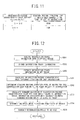
- FIG. 12 is a flowchart illustrating an unexpectedness prediction sensitivity determination process.
- FIG. 13 is a flowchart illustrating details of the process executed in step S205.
- the present embodiment is different from the first embodiment in that steps S701 to S704 in FIG. 12 are used instead of steps S204 to S207 in FIG. 4 and steps S801 and S802 in FIG. 13 are used instead of steps S403 and S404 in FIG. 6 .
- step S701 the intersection standard driving operation level determining unit 14a calculates a standard deviation (hereinafter, also referred to as an intersection passage characteristic value standard deviation) ⁇ max ⁇ of the intersection passage characteristic value ⁇ max for each intersection based on the intersection travel information received from the plural vehicles C among the intersection travel information extracted in step S203.
- the intersection standard driving operation level determining unit 14a calculates the intersection passage characteristic value standard deviation ⁇ max ⁇ with respect to all the intersections.
- FIG. 14 is a diagram illustrating the relationship between the intersection passage characteristic value standard deviation and the standard driving operation level of the driver.
- the intersection standard driving operation level determining unit 14a determines the standard driving operation level of the driver when turning to the right or left at the intersection for each intersection based on the intersection passage characteristic value standard deviation ⁇ max ⁇ calculated in step S701. Specifically, as shown in FIG. 13 , the intersection standard driving operation level determining unit 14a initializes the variable j to 0 (step s401). Subsequently, the intersection standard driving operation level determining unit 14a adds 1 to the variable j (step S402). Subsequently, the intersection standard driving operation level determining unit 14a selects the intersection passage characteristic value standard deviation ⁇ max ⁇ corresponding to the intersection whose intersection ID is equal to the variable j from among the calculated intersection passage characteristic value standard deviation ⁇ max ⁇ (step S801).
- the intersection standard driving operation level determining unit 14a determines the standard driving operation level of the driver when turning to the right or left at the intersection whose intersection ID is equal to the variable j based on the selected intersection passage characteristic value standard deviation ⁇ max ⁇ . Specifically, as shown in FIG. 14 , if the selected intersection passage characteristic value standard deviation ⁇ max ⁇ is equal to or greater than 0 (deg/s) and smaller than ⁇ 1 (deg/s), the intersection standard driving operation level determining unit 14a determines that the standard driving operation level of the driver when turning to the right or left at the intersection whose intersection ID is equal to the variable j is "low.
- the intersection standard driving operation level determining unit 14a determines that the standard driving operation level of the driver when turning to the right or left at the intersection whose intersection ID is equal to the variable j is "intermediate”. Further, if the selected intersection passage characteristic value standard deviation ⁇ max ⁇ is equal to or greater than ⁇ 2 (deg/s), the intersection standard driving operation level determining unit 14a determines that the standard driving operation level of the driver when turning to the right or left at the intersection whose intersection ID is equal to the variable j is "high" (step S802).
- the intersection standard driving operation level determining unit 14a determines that as the intersection passage characteristic value standard deviation ⁇ max ⁇ is larger, the standard driving operation level of the driver when turning to the right or left at the intersection is higher. That is, at the intersection where road situations are frequently changed, the variation of the maximum yaw angular velocity ⁇ max becomes a large value. Accordingly, if the intersection passage characteristic value standard deviation ⁇ max ⁇ is a large value, it is determined that the standard driving operation level of the driver when turning to the right or left at the intersection is "high". On the other hand, at the intersection where road situations are not frequently changed, the variation of the maximum yaw angular velocity ⁇ max becomes a small value.
- intersection standard driving operation level determining unit 14a repeats the flow (steps S402, S801 and S802) until the variable j becomes equal to or greater than the total number n of the intersections (step S405).
- the intersection standard driving operation level determining unit 14a determines the standard driving operation level of the driver when turning to the right or left at the intersection with respect to all the intersections.
- step S703 the standard driving operation level-separated driver characteristic determining unit 14b selects intersection travel information associated with the intersection where the standard driving operation level of the driver determined in step S702 is "high", from among the intersection travel information extracted in step S203. Subsequently, the standard driving operation level-separated driver characteristic determining unit 14b calculates a standard deviation (hereinafter, also referred to as a vehicle-separated intersection passage characteristic value standard deviation) V ⁇ max ⁇ of the intersection passage characteristic value (yaw angular velocity maximum vehicle velocity) Vymax for each vehicle C based on the selected intersection travel information. Thus, the standard driving operation level-separated driver characteristic determining unit 14b calculates the vehicle-separated intersection passage characteristic value standard deviation V ⁇ max ⁇ with respect to all the vehicles C.
- a standard deviation hereinafter, also referred to as a vehicle-separated intersection passage characteristic value standard deviation
- FIG. 15 is a diagram illustrating the relationship between the vehicle-separated intersection passage characteristic value standard deviation and the unexpectedness prediction sensitivity.
- step S704 the unexpectedness prediction sensitivity determining unit 15 determines the unexpectedness prediction sensitivity of the driver when turning to the right or left at the intersection for each vehicle C based on road section travel information extracted in step S203 and the standard driving operation level of the driver determined in step S702. Specifically, as shown in FIG. 9 , the unexpectedness prediction sensitivity determining unit 15 selects intersection travel information associated with the intersection where the standard driving operation level of the driver determined in step S702 is "high" from among the intersection travel information extracted in step S203 (step S601).
- the unexpectedness prediction sensitivity determining unit 15 calculates a standard deviation (hereinafter, also referred to as an all vehicle intersection passage characteristic value standard deviation) Vth of the intersection passage characteristic value Vymax included in the selected intersection travel information and the unexpectedness prediction sensitivity determination threshold value ⁇ th (for example, 0.2 x Vth) (step S602). Subsequently, the unexpectedness prediction sensitivity determining unit 15 determines the unexpectedness prediction sensitivity of the driver when turning to the right or left at the intersection for each vehicle C based on a difference between the calculated all vehicle intersection passage characteristic value standard deviation Vth and the vehicle-separated intersection passage characteristic value standard deviation V ⁇ maxC ⁇ calculated in step S703.
- a standard deviation hereinafter, also referred to as an all vehicle intersection passage characteristic value standard deviation
- the unexpectedness prediction sensitivity determining unit 15 initializes the variable 1 to 0 (step S603). Subsequently, the unexpectedness prediction sensitivity determining unit 15 adds 1 to the variable 1 (step S604). Subsequently, the unexpectedness prediction sensitivity determining unit 15 selects the vehicle-separated intersection passage characteristic value standard deviation V ⁇ maxC ⁇ of the vehicle C whose vehicle ID is equal to the variable l, from among the calculated vehicle-separated intersection passage characteristic value standard deviation V ⁇ maxC ⁇ (step S605).
- the unexpectedness prediction sensitivity determining unit 15 determines the unexpectedness prediction sensitivity of the driver of the vehicle C whose vehicle ID is equal to the variable 1 when turning to the right or left at the intersection based on the subtraction result obtained by subtracting the all vehicle intersection passage characteristic value standard deviation Vth from the selected vehicle-separated intersection passage characteristic value standard deviation V ⁇ maxC ⁇ . Specifically, as shown in FIG. 16 , if the subtraction result is equal to or greater than the unexpectedness prediction sensitivity determination threshold value ⁇ th, the unexpectedness prediction sensitivity determining unit 15 determines that the unexpectedness prediction sensitivity of the driver of the vehicle C whose vehicle ID is equal to the variable 1 when turning to the right or left at the intersection is "low".
- the unexpectedness prediction sensitivity determining unit 15 determines that the unexpectedness prediction sensitivity of the driver of the vehicle C whose vehicle ID is equal to the variable 1 when turning to the right or left at the intersection is "intermediate".
- the sign-inverted threshold value (- ⁇ th) represents a numerical value obtained by multiplying the unexpectedness prediction sensitivity determination threshold value ⁇ th by "-1".
- the unexpectedness prediction sensitivity determining unit 15 determines that the unexpectedness prediction sensitivity of the driver of the vehicle C whose vehicle ID is equal to the variable 1 when turning to the right or left at the intersection is "high" (step S606).
- the unexpectedness prediction sensitivity determining unit 15 determines that as the subtraction result (V ⁇ maxC ⁇ -Vth) is smaller, the unexpectedness prediction sensitivity of the driver when turning to the right or left at the intersection is higher. That is, with respect to the vehicle C having a large variation of the yaw angular velocity maximum vehicle velocity Vymax when turning to the right or left at the intersection, it is possible to determine that the driver's skill is low.
- the subtraction result (V ⁇ maxC ⁇ -Vth) is a large value, it is determined that the unexpectedness prediction sensitivity of the driver when turning to the right or left at the intersection is "low".
- the vehicle C having a small variation of the yaw angular velocity maximum vehicle velocity Vymax when turning to the right or left at the intersection, it is possible to determine that the driver's skill is high. Accordingly, if the subtraction result (V ⁇ maxC ⁇ -Vth) is a small value, it is determined that the unexpectedness prediction sensitivity of the driver when turning to the right or left at the intersection is "high".
- the unexpectedness prediction sensitivity determining unit 15 repeats the flow (step S604 to S606) until the variable 1 becomes equal to or greater than the total number m of the vehicles (step S607).
- the unexpectedness prediction sensitivity determining unit 15 determines the unexpectedness prediction sensitivity of the driver when turning to the right or left at the intersection with respect to all the vehicles C.
- the vehicle-separated intersection passage characteristic value standard deviation V ⁇ maxC ⁇ forms a vehicle-separated statistic.
- the standard driving operation level-separated driver characteristic determining unit 14b in FIG. 1 and step S703 in FIG. 12 form a vehicle-separated statistic calculating unit.
- the all vehicle intersection passage characteristic value standard deviation Vth forms a plural-vehicle statistic.
- the unexpectedness prediction sensitivity determining unit 15 in FIG. 1 and step S704 in FIG. 12 form a plural-vehicle statistic calculating unit and an unexpectedness prediction sensitivity determination executing unit.
- the present embodiment shows the following effects in addition to the effects of (1) to (4) in the first embodiment.
- the unexpectedness prediction sensitivity determination apparatus 2 calculates the standard deviation (vehicle-separated intersection passage characteristic value standard deviation) V ⁇ maxC ⁇ of the intersection passage characteristic value Vymax for each vehicle C. Further, the unexpectedness prediction sensitivity determination apparatus 2 calculates the standard deviation (all vehicle intersection passage characteristic value standard deviation) Vth of the intersection passage characteristic value Vymax based on the intersection travel information received from the plural vehicles C.
- the unexpectedness prediction sensitivity determination apparatus 2 determines the unexpectedness prediction sensitivity of the driver when turning to the right or left at the intersection based on the difference between the vehicle-separated intersection passage characteristic value standard deviation V ⁇ maxC ⁇ and the all vehicle intersection passage characteristic value standard deviation Vth.
- the maximum yaw angular velocity ⁇ max is employed for determination of the standard driving operation level of the driver when turning to the right or left at the intersection is shown, but a different configuration may be employed.
- the yaw angular velocity maximum vehicle velocity Vymax may be employed for determination of the standard driving operation level of the driver when turning to the right or left at the intersection.
- the present embodiment is different from the first to third embodiments in that in addition to the intersection where the intersection passage characteristic values ⁇ max and Vymax are obtained, an intersection shape when the intersection is seen from a direction where the vehicle C enters the intersection is associated in the intersection travel information. Further, the present embodiment is different from the first to third embodiments in that the intersection travel information is classified according to the intersection shape for each intersection, and the standard driving operation level of the driver when turning to the right or left at the intersection is determined based on the intersection travel information classified according to the intersection shape.
- the present embodiment is different from the first embodiment in processing of step S103 in FIG. 3 and steps S204 and S205 in FIG. 4 .
- FIGS. 17A to 17D are diagrams illustrating first to fourth intersection shapes.
- step S103 the controller 9 calculates the intersection passage characteristic values (maximum yaw angular velocity and yaw angular velocity maximum vehicle velocity) ⁇ max and Vymax based on the time series data on the yaw angular velocity ⁇ and the time series data on the vehicle velocity V recorded in step S102. Subsequently, the controller 9 determines the intersection shape when the intersection is seen from the direction where the vehicle C enters the target intersection. As the intersection shape, the first to fourth shapes are employed. As shown in FIGS. 17A to 17D , the first intersection shape is a crossroad where the vehicle C can turn to the right and left and can travel straight. The second intersection shape is a T-shaped road where the vehicle C can turn to the right and can travel straight.
- the third intersection shape is a T-shaped road where the vehicle C can turn to the left and can travel straight.
- the fourth intersection shape is a T-shaped road where the vehicle C can turn to the right and left.
- the controller 9 generates intersection travel information including the calculated intersection passage characteristic values ⁇ max and V ⁇ max, an intersection shape ID indicating the intersection shape, the intersection ID of the target intersection and the vehicle ID of the vehicle C.
- the intersection shape ID refers to unique information set for each intersection shape, which can uniquely specify the intersection shape.
- step S204 the intersection standard driving operation level determining unit 14a calculates the intersection passage characteristic value average ⁇ maxAve for each intersection shape and for each intersection based on the intersection travel information received from the plural vehicles C among the intersection travel information extracted in step S203. Specifically, as shown in FIG. 5 , first, the intersection standard driving operation level determining unit 14a initializes a variable i to 0 (step S301). Subsequently, the intersection standard driving operation level determining unit 14a adds 1 to the variable i (step S302). Subsequently, the intersection standard driving operation level determining unit 14a selects the intersection travel information including the intersection ID having a numerical value equal to the variable i from among the extracted intersection travel information (step S303).
- the intersection standard driving operation level determining unit 14a classifies the selected intersection travel information according to the intersection shape. Subsequently, the intersection standard driving operation level determining unit 14a calculates the average value (intersection shape-separated intersection passage characteristic value average) ⁇ maxAve of the absolute value of the intersection passage characteristic value ⁇ max included in the intersection travel information for each intersection shape, based on the intersection travel information classified according to the intersection shape (step S304). Further, the intersection standard driving operation level determining section 14a repeats the flow (steps S302 to S304) until the variable i becomes equal to or greater than the total number n of the intersections (step 5305). Thus, the intersection standard driving operation level determining unit 14a calculates the intersection shape-separated intersection passage characteristic value average ⁇ maxAve with respect to all the intersection.
- step S205 the intersection standard driving operation level determining unit 14a determines the standard driving operation level of the driver when turning to the right or left at the intersection for each intersection shape and for each intersection, based on the intersection shape-separated intersection passage characteristic value average ⁇ maxAve calculated in step S204. Specifically, the intersection standard driving operation level determining unit 14a initializes a variable j to 0, as shown in FIG. 6 (step S401). Subsequently, the intersection standard driving operation level determining unit 14a adds 1 to the variable j (step S402).
- the intersection standard driving operation level determining unit 14a selects, from among the calculated intersection shape-separated intersection passage characteristic value average ⁇ maxAve, the intersection shape-separated intersection passage characteristic value average ⁇ maxAve corresponding to the intersection whose intersection ID is equal to the variable j (step S403). Subsequently, the intersection standard driving operation level determining unit 14a classifies the selected intersection shape-separated intersection passage characteristic value average ⁇ maxAve according to the intersection shape.
- intersection standard driving operation level determining unit 14a determines the standard driving operation level of the driver when turning to the right or left at the intersection whose intersection ID is equal to the variable j, in consideration of the intersection shape, for each intersection shape, based on the intersection shape-separated intersection passage characteristic value average ⁇ maxAve.
- the intersection standard driving operation level determining unit 14a determines that the standard driving operation level of the driver when turning to the right or left at the intersection (hereinafter, also referred to as a shape standard driving operation level) is "high”. Further, if the intersection shape is the second intersection shape or the second intersection shape, the intersection standard driving operation level determining unit 14a determines that the standard driving operation level of the driver when turning to the right or left at the intersection (shape standard driving operation level) is "intermediate”. Further, if the intersection shape is the third intersection shape, the intersection standard driving operation level determining unit 14a determines that the standard driving operation level of the driver when turning to the right or left at the intersection (shape standard driving operation level) is "low”.
- the standard driving operation level of the driver becomes higher in the order of the first and third intersection shapes > the fourth intersection shape. Accordingly, in consideration of both of the turning to the right and left at the intersection, the standard driving operation level of the driver when turning to the right or left at the intersection becomes higher in the order of the first intersection shape > the second and third intersection shapes > the fourth intersection shape.
- intersection standard driving operation level determining unit 14a determines that the standard driving operation level of the driver when turning to the right or left at the intersection (hereinafter, also referred to as a traffic state standard driving operation level) is "low".
- the intersection standard driving operation level determining unit 14a determines that the standard driving operation level of the driver when turning to the right or left at the intersection (traffic state standard driving operation level) is "high”.
- the intersection standard driving operation level determining unit 14a determines the standard driving operation level for each intersection shape when turning to the right or left at the intersection whose intersection ID is equal to the variable j based on a combination of the determination result of the shape standard driving operation level and the determination result of the traffic state standard driving operation level (step S404). Specifically, the intersection standard driving operation level determining unit 14a determines that the standard driving operation level of the driver when turning to the right or left at the intersection is higher in the order of the combinations of the shape standard driving operation level "high” and the traffic state standard driving operation level "high” > "high” and “low” > "intermediate” and "high” > "intermediate” and "high” > "low” and “high” > “low” and “low”, respectively.
- the intersection standard driving operation level determining unit 14a repeats the flow (step S402 to S404) (step S405).
- the intersection standard driving operation level determining unit 14a determines the standard driving operation level of the driver according to the intersection shape with respect to all the intersections.
- the controller 9 in FIG. 1 and step S204 in FIG. 4 form an intersection travel information classifying unit.
- the controller 9 in FIG. 1 and step S205 in FIG. 4 form a standard driving operation level determination executing unit.
- the present embodiment shows the following effects in addition to the effects of (1) to (4) in the first embodiment.
- (1) The unexpectedness prediction sensitivity determination apparatus 2 classifies the intersection travel information according to the intersection shape for each intersection. Subsequently, the unexpectedness prediction sensitivity determination apparatus 2 determines the standard driving operation level of the driver when turning to the right or left at the intersection in consideration of the intersection shape based on the intersection travel information classified according to the intersection shape.
Landscapes
- Physics & Mathematics (AREA)
- General Physics & Mathematics (AREA)
- Chemical & Material Sciences (AREA)
- Analytical Chemistry (AREA)
- Traffic Control Systems (AREA)
- Steering Control In Accordance With Driving Conditions (AREA)
Applications Claiming Priority (2)
| Application Number | Priority Date | Filing Date | Title |
|---|---|---|---|
| JP2012060433 | 2012-03-16 | ||
| PCT/JP2013/001626 WO2013136779A1 (fr) | 2012-03-16 | 2013-03-12 | Dispositif permettant de déterminer la sensibilité à la prédiction de situations inattendues |
Publications (3)
| Publication Number | Publication Date |
|---|---|
| EP2827317A1 true EP2827317A1 (fr) | 2015-01-21 |
| EP2827317A4 EP2827317A4 (fr) | 2015-05-20 |
| EP2827317B1 EP2827317B1 (fr) | 2020-01-08 |
Family
ID=49160707
Family Applications (1)
| Application Number | Title | Priority Date | Filing Date |
|---|---|---|---|
| EP13761346.9A Active EP2827317B1 (fr) | 2012-03-16 | 2013-03-12 | Dispositif permettant de déterminer la sensibilité à la prédiction de situations inattendues |
Country Status (5)
| Country | Link |
|---|---|
| US (1) | US9666066B2 (fr) |
| EP (1) | EP2827317B1 (fr) |
| JP (1) | JP5842996B2 (fr) |
| CN (1) | CN104205186B (fr) |
| WO (1) | WO2013136779A1 (fr) |
Families Citing this family (16)
| Publication number | Priority date | Publication date | Assignee | Title |
|---|---|---|---|---|
| JP6260186B2 (ja) * | 2013-10-10 | 2018-01-17 | 日産自動車株式会社 | 安全運転度判定装置 |
| JP6180968B2 (ja) * | 2014-03-10 | 2017-08-16 | 日立オートモティブシステムズ株式会社 | 車両制御装置 |
| JP6493364B2 (ja) * | 2016-11-18 | 2019-04-03 | トヨタ自動車株式会社 | 運転支援装置 |
| JP6515912B2 (ja) | 2016-12-22 | 2019-05-22 | トヨタ自動車株式会社 | 車両運転支援装置 |
| JP6544348B2 (ja) * | 2016-12-22 | 2019-07-17 | トヨタ自動車株式会社 | 車両運転支援装置 |
| EP3358542B1 (fr) * | 2017-02-01 | 2020-12-09 | Kapsch TrafficCom AG | Procédé permettant de prédire un comportement de trafic dans un réseau routier |
| US10429846B2 (en) * | 2017-08-28 | 2019-10-01 | Uber Technologies, Inc. | Systems and methods for communicating intent of an autonomous vehicle |
| JP7062898B2 (ja) * | 2017-09-07 | 2022-05-09 | 株式会社デンソー | 衝突回避装置 |
| EP3678108A4 (fr) * | 2018-10-25 | 2020-07-08 | Beijing Didi Infinity Technology and Development Co., Ltd. | Procédé et système destinés à déterminer si une installation routière cible est présente à une intersection |
| CN111291916B (zh) * | 2018-12-10 | 2023-05-23 | 北京嘀嘀无限科技发展有限公司 | 驾驶行为安全性预测方法、装置、电子设备及存储介质 |
| JP7316064B2 (ja) * | 2019-03-08 | 2023-07-27 | 株式会社Subaru | 車両の制御装置、車両の制御方法及びプログラム |
| CN115210789B (zh) * | 2020-03-09 | 2023-11-28 | 本田技研工业株式会社 | 信息提供系统、信息提供方法以及存储介质 |
| US12051283B1 (en) | 2021-03-01 | 2024-07-30 | State Farm Mutual Automobile Insurance Company | Systems and methods of collapse of driving data to determine spatial averages of vehicle paths within an intersection |
| US12169985B1 (en) | 2021-03-01 | 2024-12-17 | State Farm Mutual Automobile Insurance Company | Systems and methods for determining direction of vehicle path through intersection |
| JP7501503B2 (ja) * | 2021-11-18 | 2024-06-18 | トヨタ自動車株式会社 | 車両挙動推定システム及び車両挙動推定方法 |
| JP2024019849A (ja) * | 2022-08-01 | 2024-02-14 | 株式会社Subaru | 車両の走行制御装置 |
Family Cites Families (17)
| Publication number | Priority date | Publication date | Assignee | Title |
|---|---|---|---|---|
| JP2000268297A (ja) * | 1999-03-16 | 2000-09-29 | Nissan Motor Co Ltd | 安全運転評価装置 |
| JP3593502B2 (ja) * | 2001-01-16 | 2004-11-24 | 株式会社データ・テック | 車両の運転技術診断システム及びその構成用品、運転技術診断方法 |
| JP3882541B2 (ja) * | 2001-07-09 | 2007-02-21 | 日産自動車株式会社 | 運転者将来状況予測装置 |
| JP3991804B2 (ja) * | 2002-07-24 | 2007-10-17 | 日産自動車株式会社 | 運転者将来状況予測装置 |
| WO2005003885A2 (fr) * | 2003-07-07 | 2005-01-13 | Sensomatix Ltd. | Systeme d'information routiere |
| JP4367431B2 (ja) * | 2005-10-26 | 2009-11-18 | トヨタ自動車株式会社 | 車両用運転支援システム |
| US7659827B2 (en) * | 2006-05-08 | 2010-02-09 | Drivecam, Inc. | System and method for taking risk out of driving |
| US7706964B2 (en) * | 2006-06-30 | 2010-04-27 | Microsoft Corporation | Inferring road speeds for context-sensitive routing |
| JP2008046759A (ja) * | 2006-08-11 | 2008-02-28 | Toyota Central Res & Dev Lab Inc | 運転支援装置 |
| KR100864178B1 (ko) * | 2007-01-18 | 2008-10-17 | 팅크웨어(주) | 속도에 따른 주행상태 감지방법 및 그 방법을 이용한교통정보 제공 시스템 |
| JP5326230B2 (ja) * | 2007-06-19 | 2013-10-30 | 住友電気工業株式会社 | 車両運転支援システム、運転支援装置、車両及び車両運転支援方法 |
| JP5499277B2 (ja) * | 2008-01-22 | 2014-05-21 | 株式会社国際電気通信基礎技術研究所 | 危険運転予防意識判定システムおよび危険運転予防意識判定方法 |
| JP5057167B2 (ja) * | 2008-10-30 | 2012-10-24 | アイシン・エィ・ダブリュ株式会社 | 安全運転評価システム及び安全運転評価プログラム |
| JP5303393B2 (ja) * | 2009-08-04 | 2013-10-02 | 本田技研工業株式会社 | 車両用運転支援装置 |
| JP5469430B2 (ja) * | 2009-10-23 | 2014-04-16 | 富士重工業株式会社 | 右折時運転支援装置 |
| JP5811776B2 (ja) | 2011-11-01 | 2015-11-11 | トヨタ自動車株式会社 | 車両ドライバの特定装置及び車両ドライバの特定方法 |
| EP2827320B1 (fr) * | 2012-03-16 | 2020-01-08 | Nissan Motor Co., Ltd | Dispositif permettant de déterminer la sensibilité à la prédiction de situations inattendues |
-
2013
- 2013-03-12 WO PCT/JP2013/001626 patent/WO2013136779A1/fr not_active Ceased
- 2013-03-12 US US14/384,500 patent/US9666066B2/en active Active
- 2013-03-12 JP JP2014504702A patent/JP5842996B2/ja active Active
- 2013-03-12 CN CN201380013064.9A patent/CN104205186B/zh active Active
- 2013-03-12 EP EP13761346.9A patent/EP2827317B1/fr active Active
Also Published As
| Publication number | Publication date |
|---|---|
| JPWO2013136779A1 (ja) | 2015-08-03 |
| CN104205186B (zh) | 2017-05-10 |
| CN104205186A (zh) | 2014-12-10 |
| EP2827317B1 (fr) | 2020-01-08 |
| EP2827317A4 (fr) | 2015-05-20 |
| US9666066B2 (en) | 2017-05-30 |
| WO2013136779A1 (fr) | 2013-09-19 |
| US20150057914A1 (en) | 2015-02-26 |
| JP5842996B2 (ja) | 2016-01-13 |
Similar Documents
| Publication | Publication Date | Title |
|---|---|---|
| EP2827317B1 (fr) | Dispositif permettant de déterminer la sensibilité à la prédiction de situations inattendues | |
| EP2827320B1 (fr) | Dispositif permettant de déterminer la sensibilité à la prédiction de situations inattendues | |
| JP5263312B2 (ja) | 渋滞判定装置、及び車両制御装置 | |
| US9514642B2 (en) | Method for detecting traffic jams using a wireless vehicle to vehicle communication system | |
| JP5900454B2 (ja) | 車両用車線案内システム及び車両用車線案内方法 | |
| US20210031804A1 (en) | Vehicle traveling control apparatus | |
| US9150221B2 (en) | Vehicle controller, control method for vehicle and control system for vehicle | |
| JPWO2019031407A1 (ja) | 判定装置、判定方法、及び、プログラム | |
| CN111033589A (zh) | 车道信息管理方法、行驶控制方法及车道信息管理装置 | |
| CN103201777B (zh) | 用于估计局部交通流量的系统和方法 | |
| KR20160047268A (ko) | 차로 변경 예측 장치 및 차로 변경 예측 방법 | |
| JP2018194954A (ja) | 道路リンク情報更新装置及び車両制御システム | |
| JP3593976B2 (ja) | 車両間通信システム及び装置 | |
| EP3179464B1 (fr) | Procédé d'alarme de virage de véhicule et dispositif d'alarme de retournement de véhicule | |
| JP2017191502A (ja) | 運転支援システム | |
| JP6561913B2 (ja) | 経路情報提供装置 | |
| US12499762B2 (en) | Support target intersection extraction system and vehicle support device | |
| WO2013136780A1 (fr) | Système permettant de déterminer la sensibilité à la prédiction de situations inattendues | |
| JP2019168899A (ja) | 渋滞情報判定装置 |
Legal Events
| Date | Code | Title | Description |
|---|---|---|---|
| PUAI | Public reference made under article 153(3) epc to a published international application that has entered the european phase |
Free format text: ORIGINAL CODE: 0009012 |
|
| 17P | Request for examination filed |
Effective date: 20140909 |
|
| AK | Designated contracting states |
Kind code of ref document: A1 Designated state(s): AL AT BE BG CH CY CZ DE DK EE ES FI FR GB GR HR HU IE IS IT LI LT LU LV MC MK MT NL NO PL PT RO RS SE SI SK SM TR |
|
| AX | Request for extension of the european patent |
Extension state: BA ME |
|
| RA4 | Supplementary search report drawn up and despatched (corrected) |
Effective date: 20150420 |
|
| RIC1 | Information provided on ipc code assigned before grant |
Ipc: G08G 1/16 20060101AFI20150414BHEP Ipc: G08G 1/01 20060101ALI20150414BHEP |
|
| DAX | Request for extension of the european patent (deleted) | ||
| STAA | Information on the status of an ep patent application or granted ep patent |
Free format text: STATUS: EXAMINATION IS IN PROGRESS |
|
| 17Q | First examination report despatched |
Effective date: 20170222 |
|
| GRAP | Despatch of communication of intention to grant a patent |
Free format text: ORIGINAL CODE: EPIDOSNIGR1 |
|
| STAA | Information on the status of an ep patent application or granted ep patent |
Free format text: STATUS: GRANT OF PATENT IS INTENDED |
|
| INTG | Intention to grant announced |
Effective date: 20190724 |
|
| GRAJ | Information related to disapproval of communication of intention to grant by the applicant or resumption of examination proceedings by the epo deleted |
Free format text: ORIGINAL CODE: EPIDOSDIGR1 |
|
| STAA | Information on the status of an ep patent application or granted ep patent |
Free format text: STATUS: EXAMINATION IS IN PROGRESS |
|
| GRAR | Information related to intention to grant a patent recorded |
Free format text: ORIGINAL CODE: EPIDOSNIGR71 |
|
| GRAS | Grant fee paid |
Free format text: ORIGINAL CODE: EPIDOSNIGR3 |
|
| STAA | Information on the status of an ep patent application or granted ep patent |
Free format text: STATUS: GRANT OF PATENT IS INTENDED |
|
| GRAA | (expected) grant |
Free format text: ORIGINAL CODE: 0009210 |
|
| STAA | Information on the status of an ep patent application or granted ep patent |
Free format text: STATUS: THE PATENT HAS BEEN GRANTED |
|
| INTC | Intention to grant announced (deleted) | ||
| AK | Designated contracting states |
Kind code of ref document: B1 Designated state(s): AL AT BE BG CH CY CZ DE DK EE ES FI FR GB GR HR HU IE IS IT LI LT LU LV MC MK MT NL NO PL PT RO RS SE SI SK SM TR |
|
| INTG | Intention to grant announced |
Effective date: 20191203 |
|
| REG | Reference to a national code |
Ref country code: GB Ref legal event code: FG4D |
|
| REG | Reference to a national code |
Ref country code: CH Ref legal event code: EP |
|
| REG | Reference to a national code |
Ref country code: DE Ref legal event code: R096 Ref document number: 602013064848 Country of ref document: DE |
|
| REG | Reference to a national code |
Ref country code: IE Ref legal event code: FG4D |
|
| REG | Reference to a national code |
Ref country code: AT Ref legal event code: REF Ref document number: 1223659 Country of ref document: AT Kind code of ref document: T Effective date: 20200215 |
|
| REG | Reference to a national code |
Ref country code: NL Ref legal event code: MP Effective date: 20200108 |
|
| REG | Reference to a national code |
Ref country code: LT Ref legal event code: MG4D |
|
| PG25 | Lapsed in a contracting state [announced via postgrant information from national office to epo] |
Ref country code: PT Free format text: LAPSE BECAUSE OF FAILURE TO SUBMIT A TRANSLATION OF THE DESCRIPTION OR TO PAY THE FEE WITHIN THE PRESCRIBED TIME-LIMIT Effective date: 20200531 Ref country code: RS Free format text: LAPSE BECAUSE OF FAILURE TO SUBMIT A TRANSLATION OF THE DESCRIPTION OR TO PAY THE FEE WITHIN THE PRESCRIBED TIME-LIMIT Effective date: 20200108 Ref country code: FI Free format text: LAPSE BECAUSE OF FAILURE TO SUBMIT A TRANSLATION OF THE DESCRIPTION OR TO PAY THE FEE WITHIN THE PRESCRIBED TIME-LIMIT Effective date: 20200108 Ref country code: NO Free format text: LAPSE BECAUSE OF FAILURE TO SUBMIT A TRANSLATION OF THE DESCRIPTION OR TO PAY THE FEE WITHIN THE PRESCRIBED TIME-LIMIT Effective date: 20200408 Ref country code: LT Free format text: LAPSE BECAUSE OF FAILURE TO SUBMIT A TRANSLATION OF THE DESCRIPTION OR TO PAY THE FEE WITHIN THE PRESCRIBED TIME-LIMIT Effective date: 20200108 Ref country code: NL Free format text: LAPSE BECAUSE OF FAILURE TO SUBMIT A TRANSLATION OF THE DESCRIPTION OR TO PAY THE FEE WITHIN THE PRESCRIBED TIME-LIMIT Effective date: 20200108 |
|
| PG25 | Lapsed in a contracting state [announced via postgrant information from national office to epo] |
Ref country code: IS Free format text: LAPSE BECAUSE OF FAILURE TO SUBMIT A TRANSLATION OF THE DESCRIPTION OR TO PAY THE FEE WITHIN THE PRESCRIBED TIME-LIMIT Effective date: 20200508 Ref country code: SE Free format text: LAPSE BECAUSE OF FAILURE TO SUBMIT A TRANSLATION OF THE DESCRIPTION OR TO PAY THE FEE WITHIN THE PRESCRIBED TIME-LIMIT Effective date: 20200108 Ref country code: LV Free format text: LAPSE BECAUSE OF FAILURE TO SUBMIT A TRANSLATION OF THE DESCRIPTION OR TO PAY THE FEE WITHIN THE PRESCRIBED TIME-LIMIT Effective date: 20200108 Ref country code: GR Free format text: LAPSE BECAUSE OF FAILURE TO SUBMIT A TRANSLATION OF THE DESCRIPTION OR TO PAY THE FEE WITHIN THE PRESCRIBED TIME-LIMIT Effective date: 20200409 Ref country code: BG Free format text: LAPSE BECAUSE OF FAILURE TO SUBMIT A TRANSLATION OF THE DESCRIPTION OR TO PAY THE FEE WITHIN THE PRESCRIBED TIME-LIMIT Effective date: 20200408 Ref country code: HR Free format text: LAPSE BECAUSE OF FAILURE TO SUBMIT A TRANSLATION OF THE DESCRIPTION OR TO PAY THE FEE WITHIN THE PRESCRIBED TIME-LIMIT Effective date: 20200108 |
|
| REG | Reference to a national code |
Ref country code: DE Ref legal event code: R097 Ref document number: 602013064848 Country of ref document: DE |
|
| PG25 | Lapsed in a contracting state [announced via postgrant information from national office to epo] |
Ref country code: SK Free format text: LAPSE BECAUSE OF FAILURE TO SUBMIT A TRANSLATION OF THE DESCRIPTION OR TO PAY THE FEE WITHIN THE PRESCRIBED TIME-LIMIT Effective date: 20200108 Ref country code: MC Free format text: LAPSE BECAUSE OF FAILURE TO SUBMIT A TRANSLATION OF THE DESCRIPTION OR TO PAY THE FEE WITHIN THE PRESCRIBED TIME-LIMIT Effective date: 20200108 Ref country code: ES Free format text: LAPSE BECAUSE OF FAILURE TO SUBMIT A TRANSLATION OF THE DESCRIPTION OR TO PAY THE FEE WITHIN THE PRESCRIBED TIME-LIMIT Effective date: 20200108 Ref country code: CZ Free format text: LAPSE BECAUSE OF FAILURE TO SUBMIT A TRANSLATION OF THE DESCRIPTION OR TO PAY THE FEE WITHIN THE PRESCRIBED TIME-LIMIT Effective date: 20200108 Ref country code: RO Free format text: LAPSE BECAUSE OF FAILURE TO SUBMIT A TRANSLATION OF THE DESCRIPTION OR TO PAY THE FEE WITHIN THE PRESCRIBED TIME-LIMIT Effective date: 20200108 Ref country code: DK Free format text: LAPSE BECAUSE OF FAILURE TO SUBMIT A TRANSLATION OF THE DESCRIPTION OR TO PAY THE FEE WITHIN THE PRESCRIBED TIME-LIMIT Effective date: 20200108 Ref country code: EE Free format text: LAPSE BECAUSE OF FAILURE TO SUBMIT A TRANSLATION OF THE DESCRIPTION OR TO PAY THE FEE WITHIN THE PRESCRIBED TIME-LIMIT Effective date: 20200108 Ref country code: SM Free format text: LAPSE BECAUSE OF FAILURE TO SUBMIT A TRANSLATION OF THE DESCRIPTION OR TO PAY THE FEE WITHIN THE PRESCRIBED TIME-LIMIT Effective date: 20200108 |
|
| REG | Reference to a national code |
Ref country code: CH Ref legal event code: PL |
|
| PLBE | No opposition filed within time limit |
Free format text: ORIGINAL CODE: 0009261 |
|
| STAA | Information on the status of an ep patent application or granted ep patent |
Free format text: STATUS: NO OPPOSITION FILED WITHIN TIME LIMIT |
|
| REG | Reference to a national code |
Ref country code: AT Ref legal event code: MK05 Ref document number: 1223659 Country of ref document: AT Kind code of ref document: T Effective date: 20200108 |
|
| 26N | No opposition filed |
Effective date: 20201009 |
|
| REG | Reference to a national code |
Ref country code: BE Ref legal event code: MM Effective date: 20200331 |
|
| PG25 | Lapsed in a contracting state [announced via postgrant information from national office to epo] |
Ref country code: LU Free format text: LAPSE BECAUSE OF NON-PAYMENT OF DUE FEES Effective date: 20200312 |
|
| PG25 | Lapsed in a contracting state [announced via postgrant information from national office to epo] |
Ref country code: LI Free format text: LAPSE BECAUSE OF NON-PAYMENT OF DUE FEES Effective date: 20200331 Ref country code: IE Free format text: LAPSE BECAUSE OF NON-PAYMENT OF DUE FEES Effective date: 20200312 Ref country code: IT Free format text: LAPSE BECAUSE OF FAILURE TO SUBMIT A TRANSLATION OF THE DESCRIPTION OR TO PAY THE FEE WITHIN THE PRESCRIBED TIME-LIMIT Effective date: 20200108 Ref country code: CH Free format text: LAPSE BECAUSE OF NON-PAYMENT OF DUE FEES Effective date: 20200331 Ref country code: AT Free format text: LAPSE BECAUSE OF FAILURE TO SUBMIT A TRANSLATION OF THE DESCRIPTION OR TO PAY THE FEE WITHIN THE PRESCRIBED TIME-LIMIT Effective date: 20200108 |
|
| PG25 | Lapsed in a contracting state [announced via postgrant information from national office to epo] |
Ref country code: SI Free format text: LAPSE BECAUSE OF FAILURE TO SUBMIT A TRANSLATION OF THE DESCRIPTION OR TO PAY THE FEE WITHIN THE PRESCRIBED TIME-LIMIT Effective date: 20200108 Ref country code: BE Free format text: LAPSE BECAUSE OF NON-PAYMENT OF DUE FEES Effective date: 20200331 Ref country code: PL Free format text: LAPSE BECAUSE OF FAILURE TO SUBMIT A TRANSLATION OF THE DESCRIPTION OR TO PAY THE FEE WITHIN THE PRESCRIBED TIME-LIMIT Effective date: 20200108 |
|
| PG25 | Lapsed in a contracting state [announced via postgrant information from national office to epo] |
Ref country code: TR Free format text: LAPSE BECAUSE OF FAILURE TO SUBMIT A TRANSLATION OF THE DESCRIPTION OR TO PAY THE FEE WITHIN THE PRESCRIBED TIME-LIMIT Effective date: 20200108 Ref country code: MT Free format text: LAPSE BECAUSE OF FAILURE TO SUBMIT A TRANSLATION OF THE DESCRIPTION OR TO PAY THE FEE WITHIN THE PRESCRIBED TIME-LIMIT Effective date: 20200108 Ref country code: CY Free format text: LAPSE BECAUSE OF FAILURE TO SUBMIT A TRANSLATION OF THE DESCRIPTION OR TO PAY THE FEE WITHIN THE PRESCRIBED TIME-LIMIT Effective date: 20200108 |
|
| PG25 | Lapsed in a contracting state [announced via postgrant information from national office to epo] |
Ref country code: MK Free format text: LAPSE BECAUSE OF FAILURE TO SUBMIT A TRANSLATION OF THE DESCRIPTION OR TO PAY THE FEE WITHIN THE PRESCRIBED TIME-LIMIT Effective date: 20200108 Ref country code: AL Free format text: LAPSE BECAUSE OF FAILURE TO SUBMIT A TRANSLATION OF THE DESCRIPTION OR TO PAY THE FEE WITHIN THE PRESCRIBED TIME-LIMIT Effective date: 20200108 |
|
| PGFP | Annual fee paid to national office [announced via postgrant information from national office to epo] |
Ref country code: GB Payment date: 20260220 Year of fee payment: 14 |
|
| PGFP | Annual fee paid to national office [announced via postgrant information from national office to epo] |
Ref country code: DE Payment date: 20260219 Year of fee payment: 14 |
|
| PGFP | Annual fee paid to national office [announced via postgrant information from national office to epo] |
Ref country code: FR Payment date: 20260219 Year of fee payment: 14 |