EP2828143B1 - Usine pour l'assemblage de pièces mécaniques sur des carrosseries de véhicule - Google Patents
Usine pour l'assemblage de pièces mécaniques sur des carrosseries de véhicule Download PDFInfo
- Publication number
- EP2828143B1 EP2828143B1 EP13721082.9A EP13721082A EP2828143B1 EP 2828143 B1 EP2828143 B1 EP 2828143B1 EP 13721082 A EP13721082 A EP 13721082A EP 2828143 B1 EP2828143 B1 EP 2828143B1
- Authority
- EP
- European Patent Office
- Prior art keywords
- pallet
- section
- stations
- station
- balance support
- Prior art date
- Legal status (The legal status is an assumption and is not a legal conclusion. Google has not performed a legal analysis and makes no representation as to the accuracy of the status listed.)
- Active
Links
Images


Classifications
-
- B—PERFORMING OPERATIONS; TRANSPORTING
- B62—LAND VEHICLES FOR TRAVELLING OTHERWISE THAN ON RAILS
- B62D—MOTOR VEHICLES; TRAILERS
- B62D65/00—Designing, manufacturing, e.g. assembling, facilitating disassembly, or structurally modifying motor vehicles or trailers, not otherwise provided for
- B62D65/02—Joining sub-units or components to, or positioning sub-units or components with respect to, body shell or other sub-units or components
- B62D65/18—Transportation, conveyor or haulage systems specially adapted for motor vehicle or trailer assembly lines
-
- B—PERFORMING OPERATIONS; TRANSPORTING
- B23—MACHINE TOOLS; METAL-WORKING NOT OTHERWISE PROVIDED FOR
- B23P—METAL-WORKING NOT OTHERWISE PROVIDED FOR; COMBINED OPERATIONS; UNIVERSAL MACHINE TOOLS
- B23P19/00—Machines for simply fitting together or separating metal parts or objects, or metal and non-metal parts, whether or not involving some deformation; Tools or devices therefor so far as not provided for in other classes
- B23P19/04—Machines for simply fitting together or separating metal parts or objects, or metal and non-metal parts, whether or not involving some deformation; Tools or devices therefor so far as not provided for in other classes for assembling or disassembling parts
-
- B—PERFORMING OPERATIONS; TRANSPORTING
- B23—MACHINE TOOLS; METAL-WORKING NOT OTHERWISE PROVIDED FOR
- B23P—METAL-WORKING NOT OTHERWISE PROVIDED FOR; COMBINED OPERATIONS; UNIVERSAL MACHINE TOOLS
- B23P21/00—Machines for assembling a multiplicity of different parts to compose units, with or without preceding or subsequent working of such parts, e.g. with program control
- B23P21/004—Machines for assembling a multiplicity of different parts to compose units, with or without preceding or subsequent working of such parts, e.g. with program control the units passing two or more work-stations whilst being composed
-
- B—PERFORMING OPERATIONS; TRANSPORTING
- B62—LAND VEHICLES FOR TRAVELLING OTHERWISE THAN ON RAILS
- B62D—MOTOR VEHICLES; TRAILERS
- B62D65/00—Designing, manufacturing, e.g. assembling, facilitating disassembly, or structurally modifying motor vehicles or trailers, not otherwise provided for
- B62D65/02—Joining sub-units or components to, or positioning sub-units or components with respect to, body shell or other sub-units or components
- B62D65/022—Transferring or handling sub-units or components, e.g. in work stations or between workstations and transportation systems
-
- Y—GENERAL TAGGING OF NEW TECHNOLOGICAL DEVELOPMENTS; GENERAL TAGGING OF CROSS-SECTIONAL TECHNOLOGIES SPANNING OVER SEVERAL SECTIONS OF THE IPC; TECHNICAL SUBJECTS COVERED BY FORMER USPC CROSS-REFERENCE ART COLLECTIONS [XRACs] AND DIGESTS
- Y10—TECHNICAL SUBJECTS COVERED BY FORMER USPC
- Y10T—TECHNICAL SUBJECTS COVERED BY FORMER US CLASSIFICATION
- Y10T29/00—Metal working
- Y10T29/49—Method of mechanical manufacture
- Y10T29/49826—Assembling or joining
- Y10T29/49828—Progressively advancing of work assembly station or assembled portion of work
- Y10T29/49829—Advancing work to successive stations [i.e., assembly line]
-
- Y—GENERAL TAGGING OF NEW TECHNOLOGICAL DEVELOPMENTS; GENERAL TAGGING OF CROSS-SECTIONAL TECHNOLOGIES SPANNING OVER SEVERAL SECTIONS OF THE IPC; TECHNICAL SUBJECTS COVERED BY FORMER USPC CROSS-REFERENCE ART COLLECTIONS [XRACs] AND DIGESTS
- Y10—TECHNICAL SUBJECTS COVERED BY FORMER USPC
- Y10T—TECHNICAL SUBJECTS COVERED BY FORMER US CLASSIFICATION
- Y10T29/00—Metal working
- Y10T29/53—Means to assemble or disassemble
- Y10T29/534—Multiple station assembly or disassembly apparatus
-
- Y—GENERAL TAGGING OF NEW TECHNOLOGICAL DEVELOPMENTS; GENERAL TAGGING OF CROSS-SECTIONAL TECHNOLOGIES SPANNING OVER SEVERAL SECTIONS OF THE IPC; TECHNICAL SUBJECTS COVERED BY FORMER USPC CROSS-REFERENCE ART COLLECTIONS [XRACs] AND DIGESTS
- Y10—TECHNICAL SUBJECTS COVERED BY FORMER USPC
- Y10T—TECHNICAL SUBJECTS COVERED BY FORMER US CLASSIFICATION
- Y10T29/00—Metal working
- Y10T29/53—Means to assemble or disassemble
- Y10T29/534—Multiple station assembly or disassembly apparatus
- Y10T29/53417—Means to fasten work parts together
-
- Y—GENERAL TAGGING OF NEW TECHNOLOGICAL DEVELOPMENTS; GENERAL TAGGING OF CROSS-SECTIONAL TECHNOLOGIES SPANNING OVER SEVERAL SECTIONS OF THE IPC; TECHNICAL SUBJECTS COVERED BY FORMER USPC CROSS-REFERENCE ART COLLECTIONS [XRACs] AND DIGESTS
- Y10—TECHNICAL SUBJECTS COVERED BY FORMER USPC
- Y10T—TECHNICAL SUBJECTS COVERED BY FORMER US CLASSIFICATION
- Y10T29/00—Metal working
- Y10T29/53—Means to assemble or disassemble
- Y10T29/53539—Means to assemble or disassemble including work conveyor
-
- Y—GENERAL TAGGING OF NEW TECHNOLOGICAL DEVELOPMENTS; GENERAL TAGGING OF CROSS-SECTIONAL TECHNOLOGIES SPANNING OVER SEVERAL SECTIONS OF THE IPC; TECHNICAL SUBJECTS COVERED BY FORMER USPC CROSS-REFERENCE ART COLLECTIONS [XRACs] AND DIGESTS
- Y10—TECHNICAL SUBJECTS COVERED BY FORMER USPC
- Y10T—TECHNICAL SUBJECTS COVERED BY FORMER US CLASSIFICATION
- Y10T29/00—Metal working
- Y10T29/53—Means to assemble or disassemble
- Y10T29/53539—Means to assemble or disassemble including work conveyor
- Y10T29/53543—Means to assemble or disassemble including work conveyor including transporting track
- Y10T29/53548—Means to assemble or disassemble including work conveyor including transporting track and work carrying vehicle
Definitions
- the present invention relates to a plant intended to carry out the assembly of mechanical parts on vehicle bodies.
- mechanical parts means both the engine of the vehicle and/or mechanical parts of the transmission (gearbox, axles, etc.), and any other mechanical part destined to be assembled on a vehicle body/bodywork, such as the front and rear suspension, also including the associated springs and shock absorbers.
- a plant of this type is known from EP2340982 , comprising an assembly line divided into two sections, which are mounted one above the other, the first beneath the second.
- a plurality of pallets, on which the mechanical parts to be assembled on each body are arranged in sequence and according to a preestablished layout, are moved along the first section in a first determined direction.
- the completed pallets are then moved to the second section by an elevator, and here they are moved in a second direction, opposite to the first, after having had a body coupled to each pallet, the body being brought to the plant by a conveyor that is not part of the plant.
- Each of the bodies is thus supported by a corresponding pallet, directly on the pallet together with the parts to be assembled.
- the plant described although satisfactory, has several drawbacks. To start with, it requires a series of operations to separate the bodies from the conveyor and then mount them on it again or on another conveyor, and to mount and dismount the bodies on/from the pallets, operations that can also require the involvement of one or more workers. Furthermore, the body can be subjected to undesired mechanical stress during assembly operations.
- the object of the present invention is therefore to overcome the drawbacks of the prior art and, in particular, to provide an assembly plant relatively simple to realize, of high reliability and where all body handling operations to and from the pallets can be carried out entirely automatically.
- a plant for assembling mechanical parts on vehicle bodies is therefore provided, as defined in Claim 1.
- the assembly plant of the invention comprises an assembly line along which a plurality of pallets are circulated in a closed loop; the assembly line is divided into a first and a second section comprising a plurality of first and second stations, respectively; the pallets sequentially advance in a first predetermined direction along the first section where they are progressively loaded, in the first stations, with a predetermined group of mechanical parts to be assembled, arranged on each pallet according to a defined layout, after which the pallet sequentially advance along the second section, in a second direction, opposite to the first, where the predetermined group of mechanical parts carried by each pallet is progressively assembled in sequence, in the second stations, on a respective vehicle body.
- a conveyor for transporting bodies also forms an integral part of the assembly plant, the conveyor being arranged at least partially parallel to the second section so as to run above the second stations; a plurality of balance supports run along the conveyor, each integrally provided with a body, and it is these balance supports that, according to the invention, are integrally coupled to the pallets in the second section of the assembly line, without ever separating the bodies from the balance supports.
- the plant according to the invention also comprises a coupling station, arranged immediately upstream of the second section, with reference to the pallet movement direction along the second section, and provided with means for integrally coupling each pallet to a balance support so that the latter is supported by the pallet; and a decoupling station, arranged immediately downstream of the second section, with reference to the pallet movement direction along the second section, and provided with means for decoupling the pallets from the balance supports.
- each pallet is equipped with its own fastening means, which can be selectively engaged and released in order to integrally secure a balance support to it; and with elastic means able to receive the balance support resting on them in order to remain compressed between the latter and the pallet when the fastening means are engaged.
- the coupling and decoupling stations comprise means for selectively controlling the engagement or release of the fastening means of each pallet; means for carrying out a relative vertical movement between a pallet and a respective balance support that are positioned on said stations; and selectively engageable, vertical positioning means for the balance supports, able to block any upward vertical movements of the balance support present each time on the station.
- the operation of securing the bodies on the pallets can be carried out entirely automatically in the coupling (or "marriage") and decoupling (or “demarriage”) stations.
- the bodies are not directly supported by the pallets, but continue to be supported by the conveyor's balance supports, the weight of which is supported by the springs of the pallets. The balance supports can thus absorb possible stress produced by the assembly operations.
- the second section is implemented as a modular scaffolding framework that provides, for each second station in which assembly operations must be carried out from beneath vehicle's body, a deck suspended above the first section and arranged vertically between the first and the second section, without interfering with the first stations; the deck is equipped with automatic or manual assembly means, for example electric screwdrivers, and can accommodate and support one or more workers.
- automatic or manual assembly means for example electric screwdrivers
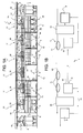
- reference numeral 1 indicate, as a whole, a plant for assembling mechanical parts 2, known and only illustrated schematically for simplicity, on vehicle bodies 3; the plant 1 comprises an assembly line 4 along which a plurality of pallets 5 are circulated in a closed loop; the line 4, on the whole of known type, thus constitutes an endless loop conveyor line for the pallets 5 along the aforementioned closed loop that, in the preferred embodiment, is arranged parallel to a vertical plane defined by the plane of the sheet in Figure 1A .
- the line 4 is divided into a first section 6 and into a second section 7, which is arranged over the first section 6 in the preferred embodiment shown; sections 6 and 7 have the same extension in the direction of movement of the pallets 5, which is straight in the example shown, and a lifting station 8 and a lowering station 9, both of known type, are arranged at the beginning and end of the first section 6 for transferring the pallets 5 to and from the second section 7.
- Section 6 comprises a plurality of sequentially arranged stations 10 and the pallets 5 advance in sequence, in a line one behind the other, in a first predetermined direction, indicated also in versus by arrow V1 in Figure 1B , along the entire first section 6; in the various stations 10, the pallets 5 are progressively loaded with a predetermined group of mechanical parts 2 to be assembled, arranged on each pallet 5 according to a defined layout, the pallets 5 subsequently being transferred, one at a time, onto the second section 7, along which they advance in sequence, in a second direction, opposite to the first and indicated also in versus in Figure 1B by arrow V2.
- section 7 comprises a plurality of stations 11, where the predetermined group of mechanical parts 2 carried by each pallet 5 are progressively assembled in sequence, in stations 11, on a respective vehicle body 3, in an essentially known manner.
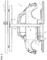
- each pallet 5 comprises a framework 12 provided with floating plates 13 (for example, on spheres, not shown for simplicity) at opposite ends that, in turn, carry a front sub-pallet or platform 15 and a rear sub-pallet or platform 14, axially slidable in direction D, these being provided, as can the central portion of the framework 12 if necessary, with known equipment 16 for supporting the parts 2 to be assembled.
- floating plates 13 for example, on spheres, not shown for simplicity
- a conveyor 17, of the aerial type also forms an integral part of the plant 1, this being arranged at least partially parallel to the second section 7 and running above the stations 11; a plurality of balance supports 18, on the whole of known type and each integrally provided with a body 3 run along the conveyor 7.
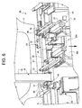
- the plant 1 also comprises a coupling station 19, arranged immediately upstream of section 7 with reference to direction V2 of movement of the pallets 5 along the second section 7, this station 19 being provided with means 21 ( Figure 5 ) for integrally coupling each pallet 5 to a balance support 18 such that the balance support 18 is supported by the pallet 5, so that the weight of the balance support 5 no longer rests on the conveyor 17.
- a coupling station 19 arranged immediately upstream of section 7 with reference to direction V2 of movement of the pallets 5 along the second section 7, this station 19 being provided with means 21 ( Figure 5 ) for integrally coupling each pallet 5 to a balance support 18 such that the balance support 18 is supported by the pallet 5, so that the weight of the balance support 5 no longer rests on the conveyor 17.
- the plant 1 comprises a decoupling station 20, arranged immediately downstream of the second section 7 with reference to direction V2 of movement of the pallets 5 along section 7 and provided with means 22 for separating the pallets 5 from the balance supports 18.
- each pallet 5 ( Figure 2 ) is fitted with its own fastening means 23, which can be selectively engaged and released to integrally secure a balance support 18 to it; and with elastic means 24 able to receive the balance support 18 resting upon them, in use, such that they remain compressed between the balance support and the pallet 5 when the fastening means 23 are engaged.
- stations 19 and 20 comprise means 25, of known type and therefore only indicated schematically with a block, for selectively controlling the engagement or release of the fastening means 23 of each pallet 5 when the latter is arranged on the individual station 19 or 20; and means 26 for carrying out, as it will be seen, a relative vertical movement between a pallet 5 and a respective balance support 18 that are positioned on said stations 19 and 20.
- Stations 8 and 9 are positioned immediately upstream and downstream of the coupling 19 and decoupling 20 stations, with reference to direction V2 of movement of the pallets along the second section 7, so as to release and, respectively, take control of the pallet 5 in the position immediately next to the stations 19 and 20.
- the selectively engageable and releasable fastening means 23 of each pallet 5 comprise respective rotating fastening pins 27, fitted with hammer heads 29 ( Figure 7 ), and respective transport pins 28; pins 27 are suitable for coupling by entering respective bottom seats 30 of the balance supports 18; the means 25 of selectively engaging and releasing the fastening means 23 of stations 19 and 20 therefore simply comprise means for rotating pins 27, which, for example, could be known hydraulic or pneumatic pushers, not shown for simplicity, placed in opportune positions and acting on, for example, tangential positioning elements, not shown for simplicity, of pins 27.
- the rotation of pins 27 could be pneumatically, hydraulically, or electrically controlled by actuators carried on board the pallets 5 and that are controlled by control means 25 in any manner known to persons skilled in the field.
- At least one pair of pins 28 are axially moveable in a telescopic manner and this movement can also be controlled by the control means 25 in a manner obvious for persons skilled in the field.
- stations 19 and 20 are provided with selectively engageable, vertical positioning means 32 for the balance supports 18, able to block upward vertical movements of the balance support 18. present each time on the station 19 or 20.
- these vertical positioning means 32 are constituted by slipper arms 31 equipped with a pneumatic or hydraulic feed drive 33, which slide perpendicularly to the feed direction of the pallets 5 along section 7.
- each balance support 18 comprises a C-shaped portal element 34, within which a respective body 3 is supported in a known manner, and a pair of side-members or longerons 35 fixed to respective opposite ends of the portal element 34 and projecting from it in a direction of extension of the conveyor 17, in the illustrated case in point, in the feed direction V2 of the pallets 5 in section 7, so that the balance support 18 has the overall aspect of a loading fork;
- the side-members 35 are provided with known releasable securing means 36 for securing the body 3; according to the invention, each of them is also provided with a flange 37 ( Figures 5 and 6 ) that supports the seats 30.
- each balance support 18 comprises universal mounting means 38 for mounting on the conveyor 17, able to allow limited vertical movements of the balance support 18 with respect to the conveyor 17; the latter can be any known type of aerial conveyor.
- the positioning means 32 with the associated drive 33 of at least the decoupling station 20 are mounted on a vertically moveable slide 38b and, together with the latter, constitute the means 26c of relative vertical movement, as will be seen, between a balance support 18 and its associated pallet 5; whereas, at least coupling station 19 is provided with means 39 for raising a pallet 5 positioned on station 19 to the balance support 18; these means 39, schematically indicated with a block, constitute the means 26b of relative vertical movement, as will be seen, between a balance support 18 and its associated pallet 5.
- the coupling 19 and decoupling 20 stations comprise first centring means 40, constituted by conical pins in the case in point, mating with second centring means 41 carried by each balance support 18, constituted in the case in point by through holes or seats 41 made through the flange 37 of each side-member 35.
- Pins 40 are preferably mounted on vertically movable slides 42, like that shown in Figure 6 .
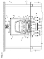
- the second section 7 is implemented as a modular scaffolding framework 43 that provides, for each station 11 in which the assembly operations of the parts 2 must be carried out from beneath body 3 of the vehicle, a deck 44 ( Figure 1A ), which is suspended above section 6, arranged vertically between the first section 6 and the second section 7 and at a height that does not interfere with stations 10; the deck 44 is equipped with automatic or manual assembly means 45 ( Figure 4 ), for example electric screwdrivers, and can accommodate and support one or more workers ( Figure 1A ).
- the bodies 3 are conveyed to the line 4 of circular conveyance of the pallets 5 and assembly of the parts 2, by conveyor 17 and, without being removed from the balance supports 18, arrive at station 19, one at a time, together with a pallet 5 "complete” with the parts 2 to be assembled and which has be controlled in a known manner in an optical control station 46; the pallet 5 is raised to section 7 by the elevator 8.
- the balance support 18 is centred, with respect to the pallet 5 and station 19, by raising pins 40 via the slides 42, so that they fit into the seats or holes 41. Then the arms 31 are extended perpendicularly to the side-members 35, until the positioning means 32 are brought over the side-members 35, vertically blocking them in the upward direction; at this point, the pallet 5 is raised upwards by means 39, so as to push it against the balance support 18, which is held stationary; the springs 24 are compressed and take the weight of the balance support 18; in addition, pins 27 are engaged and inserted into the seats 30 and, lastly, pins 27 are made to rotate by the control means 25, so as to bring the heads 29 into a bayonet locking position on the flanges 37 of the side members 35. At this point, the pallet 5, the balance support 18 and the body 3 secured by it form an integral unit, which can be transported along section 7, through all the stations 11.
- the balance support 18 is first centred, by means of pins 40 and the slides 42, in a similar manner to that described for station 19.
- the arms 31 are extended perpendicularly to the side-members 35, until they block upward movement of the balance support 18 via the positioners 32.
- the balance support 18 is pushed downwards by the arms 32 and the underlying pallet 5, compressing the springs 24. This frees the heads 29 that, no longer being subjected to the axial load exerted by the springs 24, are free to rotate.
- the means 25 of station 20 (not shown, but identical to those of station 19) then rotate around the pins 27, and the springs 24, by means of their elastic release, push the pallet 5 to disengage it from the side-members 35.
- the arms 31 and the positioners 32 are released, by deactivating the slide 38b, and after having retracted them, the completed body 3 is free to be taken away by the conveyor 17 together with its balance support 18.
- the empty pallet 5 is instead returned to the lower section 6 by the lowerator 9, ready for a new cycle.
Landscapes
- Engineering & Computer Science (AREA)
- Mechanical Engineering (AREA)
- Manufacturing & Machinery (AREA)
- Chemical & Material Sciences (AREA)
- Combustion & Propulsion (AREA)
- Transportation (AREA)
- Automatic Assembly (AREA)
- Automobile Manufacture Line, Endless Track Vehicle, Trailer (AREA)
Claims (10)
- Usine (1) pour l'assemblage de pièces mécaniques sur des corps de véhicule (3), du type comprenant une ligne d'assemblage (4), le long de laquelle une pluralité de palettes (65) circule dans une boucle fermée, la ligne d'assemblage étant divisée en une première (6) et une seconde (7) sections comprenant respectivement une pluralité de premier (10) et second (11) postes, les palettes avançant de manière séquentielle dans une première direction prédéterminée (V1) le long de la première section où elles sont progressivement chargées, dans les premiers postes, avec un groupe prédéterminé de pièces mécaniques à assembler, agencées sur chaque palette selon une disposition définie, et les palettes avançant ensuite de manière séquentielle le long de la seconde section, dans une seconde direction (V2) à l'opposé de la première, où le groupe prédéterminé de pièces mécaniques portées par chaque palette est progressivement assemblé de manière séquentielle sur un corps de véhicule respectif (3) ; caractérisé en ce qu'elle comprend en outre en combinaison :i)- un convoyeur (17) agencé au moins en partie parallèlement à la seconde section (7) et au-dessus des seconds postes (11), une pluralité de supports d'équilibrage (18) s'étendant le long du convoyeur, chacun étant intégralement doté d'un desdits corps (3) ;ii)- un poste de couplage (19) agencé immédiatement en amont de la seconde section (7) en référence à la direction de mouvement de palette le long de la seconde section, doté de moyens (21) pour le couplage intégral de chaque palette (5) à un support d'équilibrage (18) de sorte que ce dernier soit supporté par la palette (5) ; etiii)- un poste de découplage (20) agencé immédiatement en aval de la seconde section (7) en référence à la direction de mouvement de palette le long du second poste, doté de moyens (22) pour la séparation des palettes (5) des supports d'équilibrage (18).
- Usine selon la revendication 1, caractérisée en ce que chaque palette (5) est dotée de ses propres moyens de fixation (23) qui peuvent être engagés et libérés sélectivement afin de fixer intégralement un support d'équilibrage (18) à celle-ci ; et de moyens élastiques (24) capables de recevoir un support d'équilibrage (18) reposant dessus dans le but de rester compressés entre ce dernier et la palette (5) lorsque les moyens de fixation (23) sont engagés.
- Usine selon la revendication 2, caractérisée en ce que lesdits postes de couplage (19) et de découplage (20) comprennent des moyens (25) pour le contrôle sélectif de l'engagement ou de la libération des moyens de fixation (23) de chaque palette ; et des moyens (26) pour la réalisation d'un mouvement vertical relatif entre une palette (5) et un support d'équilibrage respectif (18) qui sont positionnés sur lesdits postes.
- Usine selon la revendication 2 ou 3, caractérisée en ce que lesdits moyens de fixation engageables et libérables sélectivement (23) de chaque palette comprennent des broches rotatives respectives (27) dotées de têtes de marteau (29) et capables de se coupler par des sièges inférieurs respectifs (30) des supports d'équilibrage (18) ; lesdits postes de couplage et découplage comprenant des moyens (25) pour la rotation desdites broches (27).
- Usine selon la revendication 4, caractérisée en ce que lesdits moyens de fixation (23) de chaque palette comprennent au moins une paire de broches (28) qui sont mobiles axialement de manière télescopique.
- Usine selon l'une quelconque des revendications 2 à 5, caractérisée en ce que les postes de couplage et découplage sont dotés de moyens de positionnement vertical (32), engageables sélectivement pour les supports d'équilibrage (18) capables de bloquer vers le haut des mouvements verticaux du support d'équilibrage présent chaque fois sur le poste (19 ; 20).
- Usine selon la revendication 6, caractérisée en ce que les moyens de positionnement (32) d'au moins le poste de découplage (20) sont montés sur une glissière mobile verticalement (38b) ; et en ce qu'au moins le poste de couplage (19) est doté de moyens (39) pour lever une palette (5) placée dessus vers le support d'équilibrage.
- Usine selon l'une quelconque des revendications précédentes, caractérisée en ce que lesdits postes de couplage (19) et découplage (20) comprennent des premiers moyens de centrage (40) s'accouplant avec des seconds moyens de centrage (41) portés par chaque dit support d'équilibrage (18).
- Usine selon l'une quelconque des revendications précédentes, caractérisée en ce que la seconde section (7) de la ligne d'assemblage est agencée au-dessus de la première section (6), lesquelles sections ont la même extension dans la direction de mouvement de palette ; un poste de levage (8) et un poste d'abaissement (9) pour le transfert de palettes vers et depuis la seconde section étant agencé au début et à la fin de la première section (6) et immédiatement en amont et en aval des postes de couplage (19) et découplage (20) en référence à la direction de mouvement de palette le long de la seconde section.
- Usine selon l'une quelconque des revendications précédentes, caractérisée en ce que chaque dit support d'équilibrage (18) comprend un élément de portique en C (34), dans lequel un corps respectif est supporté et suspendu, une paire d'éléments latéraux (35) fixés aux extrémités opposées respectives de l'élément de portique et en saillie de sorte à faire saillie de celui-ci dans une direction d'extension de convoyeur (D) de sorte que le support d'équilibrage (18) présente l'aspect global d'une fourche de chargement, lesdits éléments latéraux étant dotés de moyens de fixation libérables (36) pour la fixation du corps, et des moyens de montage universel (38) pour le montage sur le convoyeur, capables de permettre des mouvements verticaux limités du support d'équilibrage ; ledit convoyeur (17) étant un convoyeur aérien de tout type.
Applications Claiming Priority (2)
| Application Number | Priority Date | Filing Date | Title |
|---|---|---|---|
| IT000241A ITTO20120241A1 (it) | 2012-03-19 | 2012-03-19 | Impianto per assemblare parti meccaniche su scocche di veicoli |
| PCT/IB2013/052180 WO2013140340A1 (fr) | 2012-03-19 | 2013-03-19 | Usine pour l'assemblage de pièces mécaniques sur des carrosseries de véhicule |
Publications (2)
| Publication Number | Publication Date |
|---|---|
| EP2828143A1 EP2828143A1 (fr) | 2015-01-28 |
| EP2828143B1 true EP2828143B1 (fr) | 2016-05-18 |
Family
ID=46001513
Family Applications (1)
| Application Number | Title | Priority Date | Filing Date |
|---|---|---|---|
| EP13721082.9A Active EP2828143B1 (fr) | 2012-03-19 | 2013-03-19 | Usine pour l'assemblage de pièces mécaniques sur des carrosseries de véhicule |
Country Status (5)
| Country | Link |
|---|---|
| US (1) | US9533725B2 (fr) |
| EP (1) | EP2828143B1 (fr) |
| CN (1) | CN104284832B (fr) |
| IT (1) | ITTO20120241A1 (fr) |
| WO (1) | WO2013140340A1 (fr) |
Families Citing this family (11)
| Publication number | Priority date | Publication date | Assignee | Title |
|---|---|---|---|---|
| EP2923925A3 (fr) * | 2014-03-27 | 2016-01-13 | Cpm S.P.A. | Support d'équilibre universel pour le transport de carrosseries de véhicules et installation de transport équipée de celui-ci |
| EP3259097B1 (fr) * | 2015-02-19 | 2024-11-06 | KUKA Systems GmbH | Installation de fabrication et procédé |
| DE102016004484A1 (de) * | 2016-04-13 | 2017-10-19 | Eisenmann Se | Verfahren und Fertigungsanlage zur Herstellung von Fahrzeugen und Oberflächenbehandlungsanlage zur Oberflächenbehandlung von Fahrzeugkarosserien |
| RS64129B1 (sr) * | 2017-03-22 | 2023-05-31 | Comau Llc | Sistem sa montažnom linijom i univerzalnom potpornom paletom i modularnom pločom koja se spaja sa potpornom paletom; postupak za rekonfiguraciju montažne palete za upotrebu u montaži karoserija vozila |
| DE102018109934A1 (de) * | 2018-04-25 | 2019-10-31 | Eisenmann Se | Behandlungsanlage zum Behandeln von Werkstücken |
| CN109178149B (zh) * | 2018-10-22 | 2024-02-20 | 黄石鼎信机电有限公司 | 柔性液压多级举升rgv软轮面小车输送系统 |
| US12522444B2 (en) * | 2020-01-19 | 2026-01-13 | Hongbin Wen | Vehicle servicing apparatus and methods of use thereof |
| FR3107030B1 (fr) * | 2020-02-12 | 2025-07-18 | Psa Automobiles Sa | Support, pour un convoyeur suspendu, adaptable à différentes pièces de carrosserie |
| CN113798843B (zh) * | 2020-08-13 | 2023-03-21 | 中车唐山机车车辆有限公司 | 减振器装配产线传送系统及减振器装配产线 |
| CN114074255B (zh) * | 2022-01-10 | 2022-03-25 | 苏州天准科技股份有限公司 | 用于机动车热交换器的换线装置 |
| CN114802543B (zh) * | 2022-04-21 | 2023-08-18 | 中联重科股份有限公司 | 整机装配产线 |
Family Cites Families (31)
| Publication number | Priority date | Publication date | Assignee | Title |
|---|---|---|---|---|
| US3968599A (en) * | 1972-12-01 | 1976-07-13 | Harris, Beach & Wilcox | Lens blocking tools |
| JPS55160671A (en) * | 1979-06-04 | 1980-12-13 | Toyota Motor Corp | Equipment for transferring assembled parts |
| SE459081B (sv) * | 1987-10-07 | 1989-06-05 | Atlas Copco Ab | Foerfarande och anordning foer positionering av ett antal arbetsorgan relativt en bilkaross |
| DE58902062D1 (de) * | 1988-03-31 | 1992-09-24 | Kuka Schweissanlagen & Roboter | Montageeinrichtung zum automatischen fuegen von aggregaten von der unterseite her mit einer kfz-karosserie. |
| DE69317554T2 (de) * | 1992-12-04 | 1998-08-13 | Toyota Motor Co Ltd | Automatische montagevorrichtung |
| FR2722477B1 (fr) * | 1994-07-13 | 1996-08-30 | Bull Sa | Palette de transport |
| DE19523294A1 (de) * | 1995-06-27 | 1997-01-02 | Opel Adam Ag | Anlage zum Fügen der Chassis-Aggregate mit der Karosserie eines Kraftfahrzeuges |
| US6109424A (en) * | 1997-03-20 | 2000-08-29 | Fori Automation, Inc. | Chassis/body marriage lift machine |
| IT1298222B1 (it) * | 1998-02-11 | 1999-12-20 | Fata Automations S P A | Impianto per il trasporto e l'assemblaggio di scocche |
| US6427321B2 (en) * | 1999-03-22 | 2002-08-06 | General Motors Corporation | Automatic decking and automatic fastening system |
| US6554119B2 (en) * | 2000-02-07 | 2003-04-29 | Progressive Tool & Industries Co. | Flexible automotive assembly line and method |
| US6564440B2 (en) * | 2000-02-07 | 2003-05-20 | Progressive Tool & Industries Co. | Flexible automotive assembly workstation and method |
| US6557690B2 (en) * | 2000-02-07 | 2003-05-06 | Progessive Tool & Industries Co. | Interchangeable nests for supporting components on a transport system |
| JP3976223B2 (ja) * | 2000-09-14 | 2007-09-12 | 本田技研工業株式会社 | 車体搬送装置および車体搬送方法 |
| JP3976224B2 (ja) * | 2000-09-22 | 2007-09-12 | 本田技研工業株式会社 | オーバーヘッドコンベア |
| JP3946003B2 (ja) * | 2001-06-29 | 2007-07-18 | 株式会社ダイフク | 吊下げ搬送設備 |
| JP3983183B2 (ja) * | 2003-02-18 | 2007-09-26 | トヨタ車体株式会社 | 搬送設備 |
| JP4336161B2 (ja) * | 2003-08-11 | 2009-09-30 | 本田技研工業株式会社 | 車体の移載装置 |
| JP3960301B2 (ja) * | 2003-12-09 | 2007-08-15 | 日産自動車株式会社 | 自動車用ボディサイド搬送装置 |
| US20060032728A1 (en) * | 2004-08-10 | 2006-02-16 | Smith J R | Apparatus for removing vehicle from vehicle assembly conveyor system |
| BRPI0515715B1 (pt) * | 2004-10-05 | 2018-05-22 | Daifuku Co., Ltd. | Equipamento de transporte por suspensão |
| CA2601049C (fr) * | 2005-06-22 | 2011-01-11 | Daifuku Co., Ltd. | Materiel de livraison a pont roulant a friction |
| JP4453626B2 (ja) * | 2005-07-25 | 2010-04-21 | 株式会社ダイフク | 搬送設備 |
| KR101210789B1 (ko) * | 2006-03-03 | 2012-12-10 | 현대자동차주식회사 | 차체 생산 방법 |
| JP5022744B2 (ja) * | 2007-03-13 | 2012-09-12 | 本田技研工業株式会社 | 車両組立装置 |
| JP4538820B2 (ja) * | 2008-02-05 | 2010-09-08 | 株式会社ダイフク | 摩擦駆動トロリーコンベヤ |
| JP4562008B2 (ja) * | 2008-02-14 | 2010-10-13 | 株式会社ダイフク | 吊り下げ搬送装置 |
| DE102008022560B4 (de) * | 2008-04-30 | 2020-08-13 | Dr. Ing. H.C. F. Porsche Aktiengesellschaft | Fertigungslinie zur Herstellung von Kraftfahrzeugen |
| JP4752929B2 (ja) * | 2009-02-16 | 2011-08-17 | トヨタ自動車株式会社 | 車両の組立ライン |
| IT1397438B1 (it) * | 2009-12-30 | 2013-01-10 | Comau Spa | Installazione per l'assemblaggio di parti meccaniche su scocche di autoveicoli |
| CN201737074U (zh) * | 2010-05-25 | 2011-02-09 | 东风汽车股份有限公司 | 卡车装配线地沟台车堆积生产线自动停止控制装置 |
-
2012
- 2012-03-19 IT IT000241A patent/ITTO20120241A1/it unknown
-
2013
- 2013-03-19 CN CN201380015333.5A patent/CN104284832B/zh active Active
- 2013-03-19 EP EP13721082.9A patent/EP2828143B1/fr active Active
- 2013-03-19 WO PCT/IB2013/052180 patent/WO2013140340A1/fr not_active Ceased
- 2013-03-19 US US14/386,289 patent/US9533725B2/en active Active
Also Published As
| Publication number | Publication date |
|---|---|
| US9533725B2 (en) | 2017-01-03 |
| WO2013140340A1 (fr) | 2013-09-26 |
| EP2828143A1 (fr) | 2015-01-28 |
| CN104284832B (zh) | 2016-10-12 |
| CN104284832A (zh) | 2015-01-14 |
| ITTO20120241A1 (it) | 2013-09-20 |
| US20150047184A1 (en) | 2015-02-19 |
Similar Documents
| Publication | Publication Date | Title |
|---|---|---|
| EP2828143B1 (fr) | Usine pour l'assemblage de pièces mécaniques sur des carrosseries de véhicule | |
| CN104884206B (zh) | 通过升降圆台快速更换工具的机动车辆车身元件焊接方法和装置 | |
| US9045182B2 (en) | Plant for assembling mechanical parts on bodies of motor-vehicles | |
| KR101452685B1 (ko) | 차량 휠 운반용 트레이 | |
| JP7050156B2 (ja) | ビードエイペックスとスペーサとを伴う複数の積層体を処理するためのビードエイペックス格納システム及び方法 | |
| EP2873621A1 (fr) | Support de moteur à turbine à gaz | |
| KR20070083532A (ko) | 트위스트-록의 조작 장치, 처리 조립체, 고정 또는 분리장치, 및 저장 시스템 | |
| EP3313760B1 (fr) | Dispositif de rangement pour produits en céramique et analogues | |
| JP2019189207A (ja) | 外面に接触することなく航空機の胴体を支持する装置 | |
| CN104444086B (zh) | 一种地台板自动提升分离装置 | |
| RU2578917C1 (ru) | Автоматическая система загрузки ракет в самоходную пусковую установку | |
| CN108971980A (zh) | 节流阀铜件组装设备 | |
| CN108622654A (zh) | 自动上下料结构 | |
| CN105691679A (zh) | 一种全自动四工位托盘循环供料组装机 | |
| US20070140819A1 (en) | Installation and method for transferring a load between a transfer platform and a transport vehicle | |
| US20150052848A1 (en) | Tool handling system | |
| KR101644293B1 (ko) | 발사체 단 이송 및 기립장치 | |
| US2905310A (en) | Weighing conveyor | |
| CN203714845U (zh) | 全自动托盘分配机 | |
| US20090199383A1 (en) | Method and apparatus for inverting a vehicle assembly | |
| EP3381568B1 (fr) | Méthode de peinture de parties utilisant un dispositif pour soutenir desdites parties | |
| EP4403475A1 (fr) | Système et procédé de fabrication de sous-ensemble d'aéronef | |
| CN216971016U (zh) | 一种新型复合式全自动拆垛输送系统 | |
| CN106994990A (zh) | 具有三轮杠杆式牵引机构的搬运车 | |
| CN217262712U (zh) | 一种汽车后盖清洗系统用移载机 |
Legal Events
| Date | Code | Title | Description |
|---|---|---|---|
| PUAI | Public reference made under article 153(3) epc to a published international application that has entered the european phase |
Free format text: ORIGINAL CODE: 0009012 |
|
| 17P | Request for examination filed |
Effective date: 20140923 |
|
| AK | Designated contracting states |
Kind code of ref document: A1 Designated state(s): AL AT BE BG CH CY CZ DE DK EE ES FI FR GB GR HR HU IE IS IT LI LT LU LV MC MK MT NL NO PL PT RO RS SE SI SK SM TR |
|
| AX | Request for extension of the european patent |
Extension state: BA ME |
|
| DAX | Request for extension of the european patent (deleted) | ||
| GRAP | Despatch of communication of intention to grant a patent |
Free format text: ORIGINAL CODE: EPIDOSNIGR1 |
|
| INTG | Intention to grant announced |
Effective date: 20151023 |
|
| GRAS | Grant fee paid |
Free format text: ORIGINAL CODE: EPIDOSNIGR3 |
|
| GRAA | (expected) grant |
Free format text: ORIGINAL CODE: 0009210 |
|
| AK | Designated contracting states |
Kind code of ref document: B1 Designated state(s): AL AT BE BG CH CY CZ DE DK EE ES FI FR GB GR HR HU IE IS IT LI LT LU LV MC MK MT NL NO PL PT RO RS SE SI SK SM TR |
|
| REG | Reference to a national code |
Ref country code: GB Ref legal event code: FG4D |
|
| REG | Reference to a national code |
Ref country code: CH Ref legal event code: EP |
|
| REG | Reference to a national code |
Ref country code: IE Ref legal event code: FG4D Ref country code: AT Ref legal event code: REF Ref document number: 800176 Country of ref document: AT Kind code of ref document: T Effective date: 20160615 |
|
| REG | Reference to a national code |
Ref country code: DE Ref legal event code: R096 Ref document number: 602013007678 Country of ref document: DE |
|
| REG | Reference to a national code |
Ref country code: NL Ref legal event code: MP Effective date: 20160518 |
|
| REG | Reference to a national code |
Ref country code: LT Ref legal event code: MG4D |
|
| PG25 | Lapsed in a contracting state [announced via postgrant information from national office to epo] |
Ref country code: FI Free format text: LAPSE BECAUSE OF FAILURE TO SUBMIT A TRANSLATION OF THE DESCRIPTION OR TO PAY THE FEE WITHIN THE PRESCRIBED TIME-LIMIT Effective date: 20160518 Ref country code: NO Free format text: LAPSE BECAUSE OF FAILURE TO SUBMIT A TRANSLATION OF THE DESCRIPTION OR TO PAY THE FEE WITHIN THE PRESCRIBED TIME-LIMIT Effective date: 20160818 Ref country code: NL Free format text: LAPSE BECAUSE OF FAILURE TO SUBMIT A TRANSLATION OF THE DESCRIPTION OR TO PAY THE FEE WITHIN THE PRESCRIBED TIME-LIMIT Effective date: 20160518 Ref country code: LT Free format text: LAPSE BECAUSE OF FAILURE TO SUBMIT A TRANSLATION OF THE DESCRIPTION OR TO PAY THE FEE WITHIN THE PRESCRIBED TIME-LIMIT Effective date: 20160518 |
|
| REG | Reference to a national code |
Ref country code: AT Ref legal event code: MK05 Ref document number: 800176 Country of ref document: AT Kind code of ref document: T Effective date: 20160518 |
|
| PG25 | Lapsed in a contracting state [announced via postgrant information from national office to epo] |
Ref country code: HR Free format text: LAPSE BECAUSE OF FAILURE TO SUBMIT A TRANSLATION OF THE DESCRIPTION OR TO PAY THE FEE WITHIN THE PRESCRIBED TIME-LIMIT Effective date: 20160518 Ref country code: GR Free format text: LAPSE BECAUSE OF FAILURE TO SUBMIT A TRANSLATION OF THE DESCRIPTION OR TO PAY THE FEE WITHIN THE PRESCRIBED TIME-LIMIT Effective date: 20160819 Ref country code: RS Free format text: LAPSE BECAUSE OF FAILURE TO SUBMIT A TRANSLATION OF THE DESCRIPTION OR TO PAY THE FEE WITHIN THE PRESCRIBED TIME-LIMIT Effective date: 20160518 Ref country code: ES Free format text: LAPSE BECAUSE OF FAILURE TO SUBMIT A TRANSLATION OF THE DESCRIPTION OR TO PAY THE FEE WITHIN THE PRESCRIBED TIME-LIMIT Effective date: 20160518 Ref country code: LV Free format text: LAPSE BECAUSE OF FAILURE TO SUBMIT A TRANSLATION OF THE DESCRIPTION OR TO PAY THE FEE WITHIN THE PRESCRIBED TIME-LIMIT Effective date: 20160518 Ref country code: SE Free format text: LAPSE BECAUSE OF FAILURE TO SUBMIT A TRANSLATION OF THE DESCRIPTION OR TO PAY THE FEE WITHIN THE PRESCRIBED TIME-LIMIT Effective date: 20160518 Ref country code: PT Free format text: LAPSE BECAUSE OF FAILURE TO SUBMIT A TRANSLATION OF THE DESCRIPTION OR TO PAY THE FEE WITHIN THE PRESCRIBED TIME-LIMIT Effective date: 20160919 |
|
| PG25 | Lapsed in a contracting state [announced via postgrant information from national office to epo] |
Ref country code: RO Free format text: LAPSE BECAUSE OF FAILURE TO SUBMIT A TRANSLATION OF THE DESCRIPTION OR TO PAY THE FEE WITHIN THE PRESCRIBED TIME-LIMIT Effective date: 20160518 Ref country code: DK Free format text: LAPSE BECAUSE OF FAILURE TO SUBMIT A TRANSLATION OF THE DESCRIPTION OR TO PAY THE FEE WITHIN THE PRESCRIBED TIME-LIMIT Effective date: 20160518 Ref country code: CZ Free format text: LAPSE BECAUSE OF FAILURE TO SUBMIT A TRANSLATION OF THE DESCRIPTION OR TO PAY THE FEE WITHIN THE PRESCRIBED TIME-LIMIT Effective date: 20160518 Ref country code: SK Free format text: LAPSE BECAUSE OF FAILURE TO SUBMIT A TRANSLATION OF THE DESCRIPTION OR TO PAY THE FEE WITHIN THE PRESCRIBED TIME-LIMIT Effective date: 20160518 Ref country code: EE Free format text: LAPSE BECAUSE OF FAILURE TO SUBMIT A TRANSLATION OF THE DESCRIPTION OR TO PAY THE FEE WITHIN THE PRESCRIBED TIME-LIMIT Effective date: 20160518 |
|
| REG | Reference to a national code |
Ref country code: DE Ref legal event code: R097 Ref document number: 602013007678 Country of ref document: DE |
|
| PG25 | Lapsed in a contracting state [announced via postgrant information from national office to epo] |
Ref country code: PL Free format text: LAPSE BECAUSE OF FAILURE TO SUBMIT A TRANSLATION OF THE DESCRIPTION OR TO PAY THE FEE WITHIN THE PRESCRIBED TIME-LIMIT Effective date: 20160518 Ref country code: BE Free format text: LAPSE BECAUSE OF FAILURE TO SUBMIT A TRANSLATION OF THE DESCRIPTION OR TO PAY THE FEE WITHIN THE PRESCRIBED TIME-LIMIT Effective date: 20160518 Ref country code: SM Free format text: LAPSE BECAUSE OF FAILURE TO SUBMIT A TRANSLATION OF THE DESCRIPTION OR TO PAY THE FEE WITHIN THE PRESCRIBED TIME-LIMIT Effective date: 20160518 Ref country code: AT Free format text: LAPSE BECAUSE OF FAILURE TO SUBMIT A TRANSLATION OF THE DESCRIPTION OR TO PAY THE FEE WITHIN THE PRESCRIBED TIME-LIMIT Effective date: 20160518 |
|
| PLBE | No opposition filed within time limit |
Free format text: ORIGINAL CODE: 0009261 |
|
| STAA | Information on the status of an ep patent application or granted ep patent |
Free format text: STATUS: NO OPPOSITION FILED WITHIN TIME LIMIT |
|
| REG | Reference to a national code |
Ref country code: FR Ref legal event code: PLFP Year of fee payment: 5 |
|
| 26N | No opposition filed |
Effective date: 20170221 |
|
| PG25 | Lapsed in a contracting state [announced via postgrant information from national office to epo] |
Ref country code: SI Free format text: LAPSE BECAUSE OF FAILURE TO SUBMIT A TRANSLATION OF THE DESCRIPTION OR TO PAY THE FEE WITHIN THE PRESCRIBED TIME-LIMIT Effective date: 20160518 |
|
| REG | Reference to a national code |
Ref country code: CH Ref legal event code: PL |
|
| GBPC | Gb: european patent ceased through non-payment of renewal fee |
Effective date: 20170319 |
|
| PG25 | Lapsed in a contracting state [announced via postgrant information from national office to epo] |
Ref country code: MC Free format text: LAPSE BECAUSE OF FAILURE TO SUBMIT A TRANSLATION OF THE DESCRIPTION OR TO PAY THE FEE WITHIN THE PRESCRIBED TIME-LIMIT Effective date: 20160518 |
|
| REG | Reference to a national code |
Ref country code: IE Ref legal event code: MM4A |
|
| PG25 | Lapsed in a contracting state [announced via postgrant information from national office to epo] |
Ref country code: LU Free format text: LAPSE BECAUSE OF NON-PAYMENT OF DUE FEES Effective date: 20170319 |
|
| PG25 | Lapsed in a contracting state [announced via postgrant information from national office to epo] |
Ref country code: GB Free format text: LAPSE BECAUSE OF NON-PAYMENT OF DUE FEES Effective date: 20170319 Ref country code: CH Free format text: LAPSE BECAUSE OF NON-PAYMENT OF DUE FEES Effective date: 20170331 Ref country code: LI Free format text: LAPSE BECAUSE OF NON-PAYMENT OF DUE FEES Effective date: 20170331 Ref country code: IE Free format text: LAPSE BECAUSE OF NON-PAYMENT OF DUE FEES Effective date: 20170319 |
|
| REG | Reference to a national code |
Ref country code: FR Ref legal event code: PLFP Year of fee payment: 6 |
|
| PG25 | Lapsed in a contracting state [announced via postgrant information from national office to epo] |
Ref country code: MT Free format text: LAPSE BECAUSE OF NON-PAYMENT OF DUE FEES Effective date: 20170319 |
|
| PG25 | Lapsed in a contracting state [announced via postgrant information from national office to epo] |
Ref country code: AL Free format text: LAPSE BECAUSE OF FAILURE TO SUBMIT A TRANSLATION OF THE DESCRIPTION OR TO PAY THE FEE WITHIN THE PRESCRIBED TIME-LIMIT Effective date: 20160518 |
|
| PG25 | Lapsed in a contracting state [announced via postgrant information from national office to epo] |
Ref country code: HU Free format text: LAPSE BECAUSE OF FAILURE TO SUBMIT A TRANSLATION OF THE DESCRIPTION OR TO PAY THE FEE WITHIN THE PRESCRIBED TIME-LIMIT; INVALID AB INITIO Effective date: 20130319 |
|
| PG25 | Lapsed in a contracting state [announced via postgrant information from national office to epo] |
Ref country code: BG Free format text: LAPSE BECAUSE OF FAILURE TO SUBMIT A TRANSLATION OF THE DESCRIPTION OR TO PAY THE FEE WITHIN THE PRESCRIBED TIME-LIMIT Effective date: 20160518 |
|
| PG25 | Lapsed in a contracting state [announced via postgrant information from national office to epo] |
Ref country code: CY Free format text: LAPSE BECAUSE OF FAILURE TO SUBMIT A TRANSLATION OF THE DESCRIPTION OR TO PAY THE FEE WITHIN THE PRESCRIBED TIME-LIMIT Effective date: 20160518 |
|
| PG25 | Lapsed in a contracting state [announced via postgrant information from national office to epo] |
Ref country code: MK Free format text: LAPSE BECAUSE OF FAILURE TO SUBMIT A TRANSLATION OF THE DESCRIPTION OR TO PAY THE FEE WITHIN THE PRESCRIBED TIME-LIMIT Effective date: 20160518 |
|
| REG | Reference to a national code |
Ref country code: DE Ref legal event code: R082 Ref document number: 602013007678 Country of ref document: DE Representative=s name: TERPATENT PARTGMBB, DE Ref country code: DE Ref legal event code: R082 Ref document number: 602013007678 Country of ref document: DE Representative=s name: TERPATENT PATENTANWAELTE TER SMITTEN EBERLEIN-, DE |
|
| PG25 | Lapsed in a contracting state [announced via postgrant information from national office to epo] |
Ref country code: TR Free format text: LAPSE BECAUSE OF FAILURE TO SUBMIT A TRANSLATION OF THE DESCRIPTION OR TO PAY THE FEE WITHIN THE PRESCRIBED TIME-LIMIT Effective date: 20160518 |
|
| PG25 | Lapsed in a contracting state [announced via postgrant information from national office to epo] |
Ref country code: IS Free format text: LAPSE BECAUSE OF FAILURE TO SUBMIT A TRANSLATION OF THE DESCRIPTION OR TO PAY THE FEE WITHIN THE PRESCRIBED TIME-LIMIT Effective date: 20160918 |
|
| PGFP | Annual fee paid to national office [announced via postgrant information from national office to epo] |
Ref country code: DE Payment date: 20260320 Year of fee payment: 14 |
|
| PGFP | Annual fee paid to national office [announced via postgrant information from national office to epo] |
Ref country code: IT Payment date: 20260303 Year of fee payment: 14 |
|
| PGFP | Annual fee paid to national office [announced via postgrant information from national office to epo] |
Ref country code: FR Payment date: 20260323 Year of fee payment: 14 |