EP2828423B1 - Elément de support pour un dispositif de compression - Google Patents
Elément de support pour un dispositif de compression Download PDFInfo
- Publication number
- EP2828423B1 EP2828423B1 EP13716361.4A EP13716361A EP2828423B1 EP 2828423 B1 EP2828423 B1 EP 2828423B1 EP 13716361 A EP13716361 A EP 13716361A EP 2828423 B1 EP2828423 B1 EP 2828423B1
- Authority
- EP
- European Patent Office
- Prior art keywords
- suction
- carrier element
- shaft
- shells
- shell
- Prior art date
- Legal status (The legal status is an assumption and is not a legal conclusion. Google has not performed a legal analysis and makes no representation as to the accuracy of the status listed.)
- Active
Links
Images

Classifications
-
- D—TEXTILES; PAPER
- D01—NATURAL OR MAN-MADE THREADS OR FIBRES; SPINNING
- D01H—SPINNING OR TWISTING
- D01H5/00—Drafting machines or arrangements ; Threading of roving into drafting machine
- D01H5/18—Drafting machines or arrangements without fallers or like pinned bars
- D01H5/22—Drafting machines or arrangements without fallers or like pinned bars in which fibres are controlled by rollers only
-
- D—TEXTILES; PAPER
- D01—NATURAL OR MAN-MADE THREADS OR FIBRES; SPINNING
- D01H—SPINNING OR TWISTING
- D01H5/00—Drafting machines or arrangements ; Threading of roving into drafting machine
- D01H5/18—Drafting machines or arrangements without fallers or like pinned bars
- D01H5/70—Constructional features of drafting elements
- D01H5/72—Fibre-condensing guides
-
- D—TEXTILES; PAPER
- D01—NATURAL OR MAN-MADE THREADS OR FIBRES; SPINNING
- D01H—SPINNING OR TWISTING
- D01H5/00—Drafting machines or arrangements ; Threading of roving into drafting machine
- D01H5/18—Drafting machines or arrangements without fallers or like pinned bars
- D01H5/70—Constructional features of drafting elements
- D01H5/74—Rollers or roller bearings
Definitions
- the invention relates to a support element for a compression device for two juxtaposed drafting units of a spinning machine according to the preamble of claim 1.
- a variety of designs are already known, for compacting (compacting) of the votes of a drafting unit fiber material (fiber strand) downstream of a compacting device.
- a swirl-generating device is supplied.
- Such a swirl generating device consists for. Example, in a ring spinning machine from a rotor which rotates on a ring, wherein the yarn produced is wound on a rotating sleeve.
- compression means are substantially evacuated circumferential, perforated suction drums or circumferential, provided with perforations straps used.
- a special suction region is defined on the compression element using corresponding inserts within the suction drum, or within the circumferential straps.
- Such inserts can be z. B. are provided with correspondingly shaped suction slots, to which a negative pressure is applied, whereby a corresponding air flow is generated at the periphery of the respective compression element.
- the fiber material discharged by the drafting unit is guided above or else below the compacting devices used.
- Such devices are z. B. in the publications EP 947 614 B1 . DE 10 2005 010 903 A1 . DE 198 46 268 C2 . EP 1 612 309 B1 . DE 100 18 480 A1 and the CN 1712588 A shown and described.
- the publications mentioned above are essentially permanently installed compression devices, which are permanently installed following the respective drafting system. The drive of these compaction devices takes place partly via special, arranged over the length of the spinning machine drive shafts, which are either in drive connection with a suction roll or a rotating belt or permanently installed drive connection to correspondingly arranged pressure rollers of the compression device.
- Out DE10210054850A1 is a compressor device for arrangement in a drafting system downstream compressor zone known. It has at least one wear-trained system part, which is supported in its working position against a rotating roller of the drafting system, and at least one holding part, with which the system part held in its working position and / or axially and radially fixed with respect to the roller, wherein the system part and the holding part are at least positively and reversibly releasably connected to each other firmly.
- a compaction roller are received with a rotation locking roller in a bearing element, which is connected via a plate via screws with a pivotable loading arm of a drafting device.
- the drive is transmitted via friction from a directly connected to a drive output roller and its associated pressure roller on the compression roller and the rotation locking roller.
- the compacting device shown here is also intended for retrofitting to existing drafting equipment of spinning machines without compression.
- the attachment of the compression unit shown here to an existing drafting unit via a screw, as well as the threading at the axis of the pressure roller is relatively time consuming and requires an additional Einjusttechnik the distances. Similarly, the connection to a vacuum source must be made separately.
- the suction elements which are associated with a defined compression area for compressing the fiber material, are acted upon by additionally arranged lines, which are connected to a vacuum source, with a negative pressure.
- the WO2012068693 proposed an embodiment, wherein the compression element in the form of a suction drum and the pinch roller on a common support (support member) are rotatably mounted, which is fastened via fastening means on the spinning machine removable.
- the compacting device is pivoted about the support member about a pivot axis in the direction of the output roller pair of the drafting system, in each case a coaxially mounted on the respective suction drum friction wheel with the lower roller of the output roller pair of the drafting system takes a frictional connection (via friction).
- spring elements eg on the loading arm of the drafting system
- the support member is provided in the present example for the rotatable mounting of two coaxial and juxtaposed suction drums, which are attached to two adjacent drafting units, a so-called twin drafting. Under a twin drafting two adjacent drafting units are to be understood, the pressure rollers are loaded via a common pressure arm.
- a suction channel for applying a negative pressure to the compression elements is provided within the support element (carrier).
- a first end of the suction channel communicates with the respective compression element and its second end terminates in the region of the support element with which the support element is fastened in its mounted position on the spinning machine.
- the second end of the suction channel within the support element forms a coupling point for the connection of a further air channel, which is in communication with a main channel.
- the support element serves on the one hand as a receptacle and bearing element for the compression elements (eg rotatably mounted suction drums with permanently installed suction inserts) and on the other hand as a channel for applying a negative air pressure to the corresponding suction inserts of the compression units.
- the compression elements eg rotatably mounted suction drums with permanently installed suction inserts
- the invention is now based on the object, in the WO2012068693 shown and described support member with compression devices for two side by side arranged to simplify and improve arranged drafting units to ensure a simplified and cost-effective production. Likewise, the assembly of the attached to the support member shaft for the rotatable mounting of the suction drums should be simplified.
- outwardly projecting suction insert means that the suction insert of the respective half-shell extends transversely to the longitudinal direction and away from the suction channel of the half-shell, or of the conveying channel.
- the shaft is provided with two end portions, which have a smaller diameter relative to a central region of the shaft and the passage opening of the bearing element of the respective suction insert is provided with a stepped reduction in their inside diameter, wherein the, with the larger clear width provided portions of the passage openings adjoin one another coaxially and the, provided with a larger diameter than the reduced inside diameter of the passage opening central portion of the shaft within said, adjacent sections between abutment surfaces of the respective stepped reduction of the passage openings in the axial direction is fixed.
- the support element of two half-shells which can be connected to one another, its manufacture is simplified, whereby it is made possible for the half-shells to be produced as simple injection-molded parts.
- the, connected to the respective half-shell, tubular suction insert can be made in the same operation.
- suction inserts are aligned coaxially with each other.
- the shaft in the radial direction superimposed recording of the respective suction insert the shaft which is provided for rotatably supporting the suction drums, at the same time fixed in the axial direction when joining the two half-shells.
- the respective half shell of the support element and its associated suction insert form a one-piece, stable unit.
- the bearing elements are provided for radially fixing the shaft in the region of the stepped diameter reduction with coaxial with the respective passage opening recesses, the base of the respective recess serves as a stop surface for the axial fixation of the central part of the shaft and in the circumferential direction of the Deepening the middle part of the shaft fixed in the radial direction. That is, the diameter of the central portion of the shaft corresponds to the clear width of the recess and is held in this via a clearance in the radial direction.
- the proposed design of the support element enables a simple manufacturing process and at the same time simplifies the assembly of the elements connected to the support element (eg the shaft for the suction drums).
- the two half-shells are each provided with an opening for receiving a respective suction tube, which are associated with the respective suction drum, wherein the center axes of the openings in the mounted state of the support element are aligned coaxially with each other and their coaxial common axis in one parallel distance to the axis of the suction drums superimposed shaft.
- the openings open in each case in the edge region of the suction channel.
- the respective half-shell is provided with projecting to the center of the suction channel webs which extend axially and in extension to the respective opening on the side of the opening which faces the suction drums.
- the suction pipes are removably attached to the respective opening.
- This makes it possible different suction tubes as needed against each other exchange.
- the production of the two half-shells of the support element can take place without consideration of complicated injection molds, which are necessary if the suction tubes were firmly connected to the half-shells.
- the central axis of the respective suction pipe at an angle to the axis of the suction drum supporting shaft. This increases, starting from the outer suction opening of the suction tube in the direction of the opening of the half-shell, the distance between the respective suction tube and, the suction tube opposite suction drum.
- the space between the respective suction pipes and the respective suction drum can be kept so large, so that no deposits can form in this area by fiber fly.
- the suction tubes are provided with elevations and / or depressions via which they form a positive connection in the circumferential direction with elevations and / or depressions in the region of the opening of the half-shell form.
- the outer suction openings of the suction tubes lie in planes which, viewed in the horizontal direction and in the suction direction of the fiber channel, form an acute angle and move toward one another above the suction channel in the vertical direction.
- the suction opening in the space obliquely oriented suction openings an optimal suction effect is achieved with respect to the thread path, whereby a broken thread end can be quickly detected and fed to the suction channel.
- the suction opening could also be partially behind the yarn course (as seen in front view of the compacting device).
- the bearing elements of the two suction inserts of the half shells each have an additional radial support for the shaft, which is provided adjacent in the region in which the half shells lie in the mounted position to each other.
- At least one of the radial supports forms a positive connection in the half shells with the shaft, seen in the circumferential direction of the shaft. This ensures that only the suction drums mounted on the shaft via bearings rotate and the shaft stops and thus no wear occurs between the shaft and its radial supports in the bearing element.
- the shaft is provided in the region of the bearing points for the respective suction drum for the passage of air with a longitudinally aligned flattening. This allows the suction air flow in the area of the flattening of the shaft to be routed past the grease-lubricated bearings. Without such a bypass created by the proposed flattening, it may happen that the grease is forced out of the bearings by the suction air flow, which may settle on parts of the shaft or half shells. As a result, located in the suction air flow fibers can be held in the areas where the fat adheres, which can lead to blockages.
- the half shells are made of a transparent plastic material.
- the respective suction insert of the half-shells is provided with a, running on the outer circumference of the suction insert recess which in the region between the end face of the respective half-shell, with which they lie against each other and the respective, the suction insert superior face of the suction drum is arranged.
- lamellar gradations in the area of the surfaces with which the two half-shells abut each other during assembly (assembly), lamellar gradations (spring / groove principle) may be provided in order to seal off the suction channel formed by the two half-shells from the ambient air. If necessary, even circumferential sealing elements can be used.
- the sucked through the suction slots air is fed directly to the suction channel without further deflection, so that the air can be sucked without disturbing air vortex.
- connection of the two half shells wherein the two half shells are each provided with a circumferential flange, wherein - viewed in the mounted position of the two half shells - the flange of the second half shell partially surmounted the first half shell and the flange of the first Half shell completely surmounted the flange of the second half-shell and forms a positive clamping connection with this.
- This provides a connection without the use of additional connecting means (eg screws, rivets, etc.) while at the same time sealing the interior from the environment.
- the flange of the second half-shell is provided with an inwardly directed receptacle in which positively engages the outer contour of the flange of the first half-shell and the flange of the second half-shell in the region of the free transfer of the flange of the first half-shell an inwardly directed web is provided, which projects beyond the flange of the first half-shell partially.
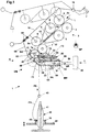
- FIG. 1 shows a schematic side view of a spinning station 1 a spinning machine (ring spinning machine) with a drafting unit 2, which is provided with an input roller pair 3, 4, a middle roller pair 5, 6 and a pair of output rollers 7, 8.
- a strap 12, 13 out which are each held around a cage, not shown in detail in its illustrated position.
- the upper rollers 4, 6, 8 of said pairs of rollers are designed as pressure rollers, which are rotatably mounted on the axes 4a, 6a, 8a on a pivotally mounted pressure arm 10.
- the pressure arm 10 is pivotally mounted about an axis 15 and, as shown schematically, acted upon by a spring element F.
- This spring element can, for. B. also be an air hose.
- the roller pairs 3, 5, 7 are driven by a drive, not shown.
- individual drives, as well as other forms of drive can be used.
- the driven lower rollers 3, 5, 7, the pressure rollers 4, 6, 8, and the belt 13 are driven via the belt 12 via friction.
- the peripheral speed of the driven roller 5 is slightly higher than the peripheral speed of the driven roller 3, so that the, the drafting unit 2 supplied fiber material in the form of a sliver L between the input roller pair 3, 4 and the middle roller pair 5, 6 subjected to a default becomes.
- the main distortion of the fiber material L takes place between the middle roller pair 5, 6 and the pair of output rollers 7, 8, wherein the output roller 7 has a substantially higher peripheral speed than the center roller 5.
- a pressure arm 10 is assigned to two adjacent drafting unit units 2 (twin drafting system). Since it is the same or partially mirror-image arranged elements of the adjacent drafting units, or compression devices, the same reference numerals are used for these parts.
- the drawn from the respective output roller pair 7, 8 stretched fiber material V is deflected downward and enters the region of a suction zone Z of a subsequent suction drum 17.
- the respective suction drum 17 is provided with extending on its circumference perforations or openings ⁇ .
- an annular suction insert 18 is arranged in each case.
- the respective suction insert 18 is an integral part of each of a half-shell H1 and H2, wherein the two half-shells form a support member 20 in the mounted state.
- the first half-shell H1 consists of a pivot profile 55 which is open on one side and a suction insert 18 fixedly connected to it.
- the second half-shell H2 has a pivoting profile 56 which opens into a suction insert 18 connected to it.
- the suction inserts 18 are aligned transversely to the longitudinal direction of the respective half-shell H1, H2.
- the profiling of the respective half shell H1, or H2 is formed so that they can be made completely in each case in an injection mold. This makes it possible to form the air-conducting areas optimally and without sharp-edged transitions, whereby deposits of contaminants within the air-conducting areas are almost impossible.
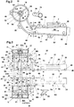
- FIG. 3 the assembly (mounting) in the direction of the arrow of the two half-shells H1, H2 is shown to a support member 20.
- an all-round closed suction channel SK is formed ( Fig. 1 . Fig. 4 ).
- the faces SF of two half-shells H1, H2 lie on each other and are pressed against each other over several distributed over the length of the two half-shells screw 48.
- the half shells are each provided with a web 49, which each have a through hole for the screws 48.
- the end faces SF may be provided with ridges and depressions (not shown), which together form a labyrinth-shaped sealing point.
- additional sealing elements (not shown) for sealing the formed suction channel SK can be provided between the end faces SF.
- the half shells H1, H2 must be provided in this area with correspondingly shaped end faces. This will be further described in an embodiment, which in Figure 7 is shown.
- the hub G extends in the half-shell H1 between the end face SF and a radially oriented web 57 which is mounted within and in the region of the free end of the suction insert 18.
- the web 57 is provided with a central passage opening U.
- the hub G extends between the end face SF and a radially oriented web 58 which is mounted within and in the region of the free end of the suction insert 18.
- the web 58 is also provided with a central passage opening U.
- the shaft 22 In the area of the opening B and the passage openings U, the shaft 22 is mounted, which has a central part 22 m, on which on both Ends each includes an end piece 22a, which have a smaller diameter than the central part 22m.
- the inside width Lw of the opening B of the respective hub G is greater outside the existing radial bearing points than the outside diameter of the respective section 22m, 22a of the shaft 22.
- the respective hub G has a longitudinal section A1 of the opening O, at which a longitudinal section A2 adjacent whose clear width Lw is smaller than the inside width Lw of the section A1 and the diameter of the portion 22m of the shaft 22.
- a stepped recess C (shoulder) is provided in each case in which the middle section 22 m of the shaft 22 is fixed in the radial direction. That is, the inside width Lw of the recess C corresponds to the diameter of the middle part 22m of the shaft 22.
- the inner space 66 which leads as an air guide channel from the suction slots S to the suction channel SK, extends from the view N (FIG. Fig.1 ) seen from behind the shaft 22, and the hub G.
- the air sucked through the suction slots is fed directly and without further deflection to the suction channel SK, whereby the air is sucked out without disturbing swirling air.
- a further web S3 may be provided ( Fig. 2 ).
- FIG. 2 one of the half shells H1 is shown in a side view. Separately shown is a suction tube 75, which is fastened in the region of the opening 77 on the half-shell H1.
- the central axis MS of the suction tube 75 extends from its attachment point in the assembled state obliquely and at an angle c to a vertical plane E, which is parallel to a, through the central axis MA of the suction drum 17 vertical plane.
- the suction tube 75 ' which is attached to the second half-shell H2, is mirror-inverted and also extends, seen in a horizontal plane, at an angle c to the central axis MA.
- the suction tubes 75, 75 ' also seen in the horizontal direction, in addition to extend at an angle k to the central axis of the suction drums 17.
- the suction tube 75 (as well as the suction tube 75 ') on a flange 70 which is provided with a cam 78.
- the respective suction tube 75, 75 ' is fixed in its installed position in its circumferential direction.
- the respective cam 78 protrudes into a recess 79 of the respective half-shell H1, H2, which are mounted in the region of the openings 77. Due to the separate mounting of the suction tubes, it is on the one hand possible, depending on the requirements, to replace them with others. On the other hand, when creating the injection mold for the production of the half-shells H1, H2, no consideration must be given to the oblique orientation of the suction pipes, whereby the injection mold can be made simple and inexpensive.
- the respective opening 77 is sealed off by a transversely extending to the suction channel web 60 relative to the suction of the suction inserts 18 indicated by a suction air stream.
- Each of the webs 60 has ( Fig.
- the respective suction drum 17 is rotatably mounted in the region of its outer end via a bearing K on an end piece 22a of the shaft 22.
- the opposing end pieces 22a of the shaft 22 have a smaller diameter than the central part 22m of the shaft 22, so that between the middle part 22m and the adjoining end pieces 22a, a shoulder is formed with a stop surface AF.
- a locking ring 23 is mounted in a groove of the shaft, which prevents the axial displacement of the suction drum during operation.
- an opening 21 is attached, which is closed by a cap 30.
- the retaining ring 23 By removing the retaining ring 23, after removing the cap 30, it is possible to easily withdraw the respective suction drum 17 from the end piece 22a of the shaft 22 in the axial direction. As a result, a quick replacement of the suction drums 17 is possible, if necessary to exchange them with other suction drums with a different arrangement of the openings ⁇ to convert the compression element to the processing of another fiber material.
- the removal of the respective suction drum can also be done only for cleaning purposes.
- the retaining ring can also z. B. be an O-ring made of rubber or a flexible clamping ring.
- the shaft 22 is in the assembly of the two half-shells H1, H2, or provided on the half-shells suction inserts 18 according to Figure 3 in axial and in radial Location fixed.
- the shaft 22 is fixed via its middle part 22m, which has a length Lm, between the abutment surfaces T1 and T2 of the recesses C.
- the stop surfaces T1, T2 of the recesses C a distance Lx to each other, which is only slightly greater than the length Lm of the central part 22m of the shaft 22.
- the shaft is fixed in the axial direction within the suction inserts 18, wherein in each case the end pieces 22a of the shaft 22 protrude through the openings U of the webs 57, 58, on which the suction drums 17 are pushed over their bearing K.
- the shaft portion 22m rests with its outer peripheral surface on the inner peripheral surface of the recess C and is thus fixed in the radial direction.
- Fig. 4a shows a sectional view xx of the shaft 22 after Fig. 4 ,
- the shaft 22 is provided in the region of the bearings K for the respective suction drum 17 for the passage of air with a longitudinally aligned flattening 82.
- the two suction inserts 18 can be provided with additional supports 52, 53 projecting into the respective opening B, on which the middle part 22m of the shaft 22 can be supported in a specific radial direction. These supports are mounted only on a partial peripheral area of the opening and aligned according to the force effects occurring.
- the supports 52, 53 can also be formed by a corresponding shape of the cross-section of the opening B in this area.
- the two suction tubes 75, 75 ' are fixed in the region of the openings 77.
- the suction tubes 75, 75 ' have at their one end a flange 70, which is provided in the region of its peripheral surface with a radially outwardly facing cam 78.
- the outer diameter of the respective flange 70 corresponds approximately to the inner diameter of the attached to the respective half-shell H1, H2 centric to the opening 77 flange 71.
- a radially outwardly projecting recess 79 is attached, the outer contour of the contour of the Cam 78 corresponds.
- the cam 78 and the recess 79 form a positive connection, when the flange 70 of the respective suction tube 75, or 75 'is inserted into the opening of the flange 71, wherein the cam 78 and the recess 79 face each other.
- the respective suction tube is fixed in the circumferential direction and takes the desired angular position with the angle c to the respective suction drum 17 a.
- the suction tubes 75, 75 ' are held in their installed position via a slight press fit.
- other fasteners can be used to hold the mounted suction tubes in their installed position.
- a clamping roller 33 is provided for each of the suction drums 17, which rests on the respective suction drum 17 via a pressure load and forms with it a clamping line P.
- the respective pinch roller 33 is rotatably mounted on an axis 32, which is held in a guide slot 73 of a U-shaped receptacle of a pressure arm 72.
- the axis 32 is slidably mounted within the guide slot 73 transversely to its longitudinal axis.
- a plunger which rests on the outer circumference of the axis 32 and is acted upon by a pressure spring F2 shown schematically.
- the opening is approximately centrally mounted at the end of the guide slot 73 and opens into a substantially closed cavity of the pressure arm 72, in which the compression spring is arranged. This supports one end at the closed end of the cavity and rests with the opposite end on a head of the plunger.
- the pressure arm 72 is pivotally mounted about a, attached to its end axes 24 in a bearing member 80, as seen from Fig.1 can be seen schematically.
- the bearing element 80 is formed on the half-shells H1, H2 mounted webs T, and T ', which are each provided with a guide 81, via which the axes 24 of the pressure arm 72 in their, in Fig.1 shown pivot position are transferred when the two half-shells H1, H2 are interconnected.
- the axes 24 via a schematically in Fig.1 shown stop edge held transversely to its pivot axis at the end of the respective guide 81.
- pinch rollers 33 are loaded against the respective suction drum 17, wherein a nip line P is formed.
- the pressure arm is pivoted over dead center until it rests on a stop 65 which is attached to the respective half-shells H1, H2.
- the axis 32 of the pinch rollers 33 is below the plane passing through the pivot axis 24 and the center axis MA of the suction drums 17. That is, the pinch roller 33 is held over dead center in this position. Further details with respect to the attachment and execution of the pinch rollers 33 can also be found in the CH705308 be removed.
- the compacting device VM is now pre-assembled and is now attached to the respective drafting system 2 (twin drafting) on the spinning machine.
- the support member 20 is inserted with the attached to the pivot profiles 55, 56 of the half shells H1, H2 axes 32 in receptacles 34 on the machine frame MR and not shown clamping elements or other means in this in Fig.1 shown pivot position held.
- the compaction device Pivot VM via the pivot axes 32 in a lower position until it rests on a, attached to the machine frame MR stop 64 and held there.
- the compacting device VM is pivoted about the axes 32 in an upper position until the mounted on the respective suction drum 17 friction rings 28 (friction wheel) rest on the respective driven roller 7 of the pair of drafting rollers 2.
- the pressure lever 10 about its pivot axis 15 of a dashed upper position ( Fig.1 ) is pivoted to a lower position, in which a pressure force is exerted on the support element 20 of the compacting device VM in the direction of the roller 7 via a leaf spring 68 fastened by means of screws to the pressure lever 10 and the web 62 secured to the leaf spring.
- a pressure force is exerted on the support element 20 of the compacting device VM in the direction of the roller 7 via a leaf spring 68 fastened by means of screws to the pressure lever 10 and the web 62 secured to the leaf spring.
- the respective friction ring 28 and thus the associated suction drum 17 is driven by the roller 7 via friction.
- the friction ring 28 may be made of an elastic material, such. B. made of rubber.
- a vacuum source SP is provided which communicates with a central suction channel 85.
- the suction channel 85 is connected via a line 86, a flexible coupling element 88 with the respective, in the direction of the suction channel 85 projecting end of the suction channel SK of the compression device VM, in conjunction. Due to the flexibility of the coupling element 88, the pivotability of the compacting device about the axis 32 is made possible.
- the coupling element 88 shown schematically may be formed on its outer circumference, so that it is positively connected to the formed suction channel SK when joining the two half-shells H1, H2 and to the outside.
- the nip line P generated by the pinch roller 33 simultaneously forms a so-called “rotation locking gap", from which the fiber material in the conveying direction FS in the form of a compressed yarn FK is supplied under rotation distribution of a ring spinning device shown schematically.
- This is provided with a ring 39 and a rotor 40, wherein the yarn is wound on a sleeve 41 to form a coil 42 (Kops).
- a yarn guide 43 is arranged between the nip line P and the rotor 40.
- the ring 39 is attached to a ring frame 44, which performs an up and down movement during the spinning process.
- the yarn FK further supplied via the nip P is conveyed via the respective suction pipe 75 and 75 'via the opening 77 under the action of the exhaust pipe 75 mounted on the support member 20 via the negative pressure source SP Vacuum sucked through the suction channel SK and the suction channel 85 is supplied.
- the respective suction opening 38 of the suction tubes 75, or 75 ' is assigned to the side of the yarn course.
- a recess X is in each case mounted on the peripheral surface of the respective suction insert 18.
- a step-shaped shoulder 90 in the region of the end faces 84 of the suction drums 17, which prevents 20 accumulated fiber fly in the center region of the support member 20 can move into the gap 87 between the suction drum 17 and the suction insert 18.
- the respective step-shaped step 90 provides a barrier to lateral displacement of deposits. Such deposits are then removed in time over cleaning intervals before they can overcome the described barrier.
- FIG Figure 5 View H
- FIG Figure 7 Another embodiment with respect to the connection of the two half-shells H1, H2 is shown in FIG Figure 5 (View H) shown, which as an enlarged partial view in Figure 7 is shown in more detail.
- the two half shells H1, H2 at their ends encircling flanges 45, 46, via which the two half-shells with each other without additional additives (eg., Pins, screws or the like) positively connected become.
- additional additives eg., Pins, screws or the like
- the flange 45 of the first half-shell H2 is provided with an inwardly pointing shoulder 92, whose inner surface 93 engages over the outer surface 94 of the half-shell H1 partially and comes to rest thereon in the mounted position. Furthermore, a flange 46 is attached to the half-shell H1, which completely overlaps or covers the flange 45 on its outer surface AL.
- the flange 46 has an L-shaped cross-sectional area which forms an inwardly directed receptacle 50 over which the flange 46 forms a positive connection with the flange 45 in the illustrated assembled position.
- the term "inside” refers to the interior of the mounted half-shells H1, H2.
- the flange 46 At the end of the L-shaped cross-section of the flange 46 is provided with an inwardly projecting web 89 which projects beyond the rear surface 91 of the flange 45 and holds the flange 45 in its shown locking position in the receptacle 50 of the flange 46. D. h., When the connection is to be released again, force is necessary to deflect the L-shaped portion of the flange 46 on the existing elasticity outwards until the web 89 is outside the surface 91 and thus the outlet of the flange 45 allows the recording 50. To facilitate assembly of the flange 46 is provided with a chamfer 95.
- a gap 36 with the distance n between the surfaces 45a and 46a of the flanges 45, 46 is provided. This prevents fibers from being trapped in this area.
- the gap 36 is sealed off from the ambient air by the inner surface 93 of the flange 45 to the outside.
Landscapes
- Engineering & Computer Science (AREA)
- Mechanical Engineering (AREA)
- Textile Engineering (AREA)
- Spinning Or Twisting Of Yarns (AREA)
Claims (18)
- Elément de support (20) destiné à un dispositif de compactage (VM) qui comporte deux tambours d'aspiration (17), un insert d'aspiration (18) étant disposé l'intérieur de chaque tambour d'aspiration (17) ;
un tambour d'aspiration (17) étant associé à une paire de rouleaux de sortie (7, 8) d'une unité d'étirage (2) d'une machine à filer ;
les tambours d'aspiration (17) étant montés de manière rotative sur un arbre (22), fixé à l'élément de support (20), au moyen d'un palier (K) ;
un conduit d'aspiration (SK) s'étendant à l'intérieur de l'élément de support (20), caractérisé en ce que l'élément de support (20) se compose de deux demi-coques (H1, H2) qui peuvent être reliées l'une à l'autre par des moyens de fixation (48), et forment une fois reliées le conduit d'aspiration (SK), chacune des demi-coques (H1, H2) comporte un insert d'aspiration (18). - Elément de support (20) selon la revendication 1, caractérisé en ce que le tambour d'aspiration (17) comportent des orifices (O) et chaque insert d'aspiration (18) comporte une fente d'aspiration (Z).
- Elément de support (20) selon la revendication 1 ou 2, caractérisé en ce que les tambours d'aspiration (17) sont placées coaxialement à distance l'un en face de l'autre avec leurs faces d'extrémité ouvertes d'un côté.
- Elément de support (20) selon l'une des revendications 1 à 3, caractérisé en ce que les inserts d'aspiration (18) sont placés coaxialement l'un en face de l'autre et chaque insert d'aspiration (18) comporte un moyeu (G) pourvu d'un orifice de passage (B) destiné à recevoir l'arbre (22), le moyeu (G) comportant un épaulement (C).
- Elément de support (20) selon la revendication 4, caractérisé en ce que l'arbre (22) est pourvu de deux parties d'extrémité (22a) qui ont un diamètre inférieur à celui d'une partie centrale (22m) de l'arbre et en ce que l'orifice de passage (B) du moyeu (G) de l'insert d'aspiration respectif (18) présente une réduction étagée de sa largeur intérieure (Lw), les parties (A1) des orifices de passage, qui ont la largeur intérieure (Lw) plus grande, étant coaxialement adjacentes l'une à l'autre et la partie centrale (22m) de l'arbre (22), dont le diamètre est supérieur à la largeur intérieure réduite (Lw) de l'orifice de passage étant à l'intérieur desdites parties adjacentes (A1) entre des surfaces de butée (T1, 12) de la réduction étagée respective des orifices de passage dans la direction axiale.
- Elément de support (20) selon l'une des revendications 1 à 5, caractérisé en ce que les deux demi-coques (H1, H2) comporte chacune un orifice (77) destiné à recevoir un tube d'aspiration (75, 75') qui est associé au tambour d'aspiration respectif (17), les axes centraux des orifices (77) étant alignés coaxialement entre eux une fois l'élément de support (20) monté, leur axe commun coaxial s'étendant parallèlement à distance de l'axe (MA) de l'arbre (22) logeant les tambours d'aspiration (17) et les orifices (77) débouchant dans le conduit d'aspiration au niveau du bord du conduit d'aspiration (SK).
- Elément de support (20) selon la revendication 6, caractérisé en ce que, dans la région des ouvertures (77), chaque demi-coque (H1, H2) est pourvue de nervures (60) qui font saillie au milieu du conduit d'aspiration (SK) et qui s'étendent axialement et dans le prolongement de l'orifice (77) respectif du côté de l'orifice qui est tourné vers le tambour d'aspiration (17).
- Elément de support (20) selon la revendication 7, caractérisé en ce que les deux nervures (60) sont à une distance (r) l'une de l'autre.
- Elément de support (20) selon l'une des revendications 6 à 8, caractérisé en ce que les tubes d'aspiration (75, 75') sont montés de manière démontable sur l'orifice respectif (77).
- Elément de support (20) selon l'une des revendications 6 à 9, caractérisé en ce que l'axe central (MS) du tube d'aspiration respectif (75, 75') s'étendent en formant un angle (c) par rapport à l'axe (MA) de l'arbre (22) portant les tambours d'aspiration (17) de sorte que la distance entre le tube d'aspiration respectif (75, 75') et le tambour d'aspiration (17), opposé au tube d'aspiration, augmente à partir de l'orifice d'aspiration plus extérieur (38) du tube d'aspiration (75, 75') par référence à la direction de l'orifice (77) de la demi-coque (H1, H2).
- Elément de support (20) selon l'une des revendications 6 à 10, caractérisé en ce que les tubes d'aspiration (75, 75') comportent des bosses et/ou des creux (78) qui forment dans la direction périphérique une liaison par complémentarité de formes avec des bosses et/ou des creux (79) situés dans la région de l'ouverture (77) de la demi-coque (H1, H2).
- Elément de support (20) selon l'une des revendications 6 à 11, caractérisé en ce que les orifices d'aspiration extérieures (38) des conduits d'aspiration (75, 75') sont situés dans des plans (E1, E2) qui forment un angle aigu (w) lorsque l'on regarde dans la direction horizontale et dans la direction d'aspiration (SR) du conduit d'aspiration (SK) et qui se déplacent l'un vers l'autre lorsque l'on regarde dans la direction verticale, au-dessus du conduit d'aspiration (SK).
- Elément de support (20) selon l'une des revendications 1 à 12, caractérisé en ce que les éléments de palier (G) des deux inserts d'aspiration (18) des demi-coques (H1, H2) comportent chacun un appui radial supplémentaire (52, 53) destiné à l'arbre (22) qui est prévue de façon adjacente dans la région dans laquelle les demi-coques (H1, H2) sont en appui l'une contre l'autre une fois dans la position montée.
- Elément de support (20) selon la revendication 13, caractérisé en ce qu'au moins un des appuis radiaux (52, 53) forme avec l'arbre (22) une liaison par complémentarité de formes lorsque l'on regarde dans la direction périphérique de l'arbre.
- Elément de support (20) selon l'une des revendications 13 ou 14, caractérisé en ce que, dans la région des paliers (K) destinés au tambour d'aspiration respectif (17), l'arbre (22) comporte, en vue du passage d'air respectif, un aplatissement (82) orienté dans la direction longitudinale.
- Elément de support (20) selon l'une des revendications précédentes, caractérisé en ce que l'insert d'aspiration respectif (18) des demi-coques (H1, H2) comporte un creux (X) qui s'étend sur la périphérie extérieure de l'insert d'aspiration et qui est disposé dans la région située entre la surface frontale (SF) de la demi-coque respective (H1, H2), avec laquelle les demi-coques viennent en appui l'une contre l'autre, et la surface d'extrémité respective (84), saillant de l'insert d'aspiration (18), du tambour d'aspiration (17).
- Elément de support (20) selon l'une des revendications précédentes, caractérisé en ce que les deux demi-coques (H1, H2) comportent chacune une bride périphérique (45, 46) ; lorsque l'on regarde dans la position montée des deux demi-coques (H1, H2), une bride (45) de la seconde demi-coque (H2) fait partiellement saillie de la première demi-coque (H1) et la bride (46) de la première demi-coque (H1) fait totalement saillie de la bride (45) de la seconde demi-coque (H2) et forme avec elle une liaison par complémentarité de formes.
- Machine à filer, en particulier machine à filer à anneaux, comprenant deux unités d'étirage adjacentes (2) qui comporte chacune une paire de rouleaux de sortie (7, 8), caractérisée en ce que ladite paire comprend l'élément de support (20) selon l'une des revendications 1 à 17, un tambour d'aspiration (17) étant associé à la paire de rouleaux de sortie (7, 8) d'une unité d'étirage (2).
Applications Claiming Priority (2)
| Application Number | Priority Date | Filing Date | Title |
|---|---|---|---|
| CH00392/12A CH706258A2 (de) | 2012-03-21 | 2012-03-21 | Tragelement für eine Verdichtungsvorrichtung. |
| PCT/IB2013/000320 WO2013140215A1 (fr) | 2012-03-21 | 2013-03-08 | Elément de support pour un dispositif de compression |
Publications (2)
| Publication Number | Publication Date |
|---|---|
| EP2828423A1 EP2828423A1 (fr) | 2015-01-28 |
| EP2828423B1 true EP2828423B1 (fr) | 2017-10-18 |
Family
ID=48095927
Family Applications (1)
| Application Number | Title | Priority Date | Filing Date |
|---|---|---|---|
| EP13716361.4A Active EP2828423B1 (fr) | 2012-03-21 | 2013-03-08 | Elément de support pour un dispositif de compression |
Country Status (6)
| Country | Link |
|---|---|
| US (1) | US9695526B2 (fr) |
| EP (1) | EP2828423B1 (fr) |
| JP (1) | JP6147328B2 (fr) |
| CN (1) | CN104520480B (fr) |
| CH (1) | CH706258A2 (fr) |
| WO (1) | WO2013140215A1 (fr) |
Cited By (1)
| Publication number | Priority date | Publication date | Assignee | Title |
|---|---|---|---|---|
| DE102020126876A1 (de) | 2020-10-13 | 2022-04-14 | Maschinenfabrik Rieter Ag | Verdichtungsvorrichtung für eine Spinnmaschine |
Families Citing this family (9)
| Publication number | Priority date | Publication date | Assignee | Title |
|---|---|---|---|---|
| CH704137A1 (de) * | 2010-11-26 | 2012-05-31 | Rieter Ag Maschf | Vorrichtung zum Verdichten eines Faserverbandes an einer Spinnmaschine sowie Spinnmaschine. |
| CH705308A1 (de) * | 2011-07-25 | 2013-01-31 | Rieter Ag Maschf | Verdichtungsvorrichtung für eine Spinnmaschine. |
| CH705307A1 (de) * | 2011-07-25 | 2013-01-31 | Rieter Ag Maschf | Spinnmaschine mit einer Verdichtungsvorrichtung. |
| CH708518A1 (de) * | 2013-09-13 | 2015-03-13 | Rieter Ag Maschf | Saugtrommel einer Vorrichtung zum Verdichten eines Fasergutes mit einer Dichtung. |
| CH709312A1 (de) * | 2014-02-27 | 2015-08-28 | Rieter Ag Maschf | Verdichtungsvorrichtung mit Saugtrommel. |
| CH713916A1 (de) * | 2017-06-23 | 2018-12-28 | Rieter Ag Maschf | Verdichtungsvorrichtung für eine Spinnmaschine. |
| DE102017130224A1 (de) * | 2017-12-15 | 2019-06-19 | Maschinenfabrik Rieter Ag | Streckwerk und Verdichtungsvorrichtung für eine Spinnereimaschine |
| DE112019005116A5 (de) * | 2018-10-12 | 2021-07-22 | TRüTZSCHLER GMBH & CO. KG | Basis für eine Textilmaschine |
| DE102019115220A1 (de) * | 2019-06-05 | 2020-12-10 | Maschinenfabrik Rieter Ag | Spinnereimaschine |
Family Cites Families (26)
| Publication number | Priority date | Publication date | Assignee | Title |
|---|---|---|---|---|
| DE10050089C2 (de) | 2000-03-08 | 2002-06-27 | Zinser Textilmaschinen Gmbh | Streckwerk für eine Spinnereimaschine |
| DE4426249C2 (de) | 1994-07-25 | 2003-08-07 | Rieter Ag Maschf | Spinnverfahren und Spinnmaschine mit abgedeckter Saugwalze am Streckwerk |
| DE19726694A1 (de) * | 1996-09-30 | 1998-04-02 | Rieter Ag Maschf | Spinnmaschine für das Kompaktspinnen mit einem Streckwerk |
| DE19846268C2 (de) | 1998-03-31 | 2002-07-04 | Schurr Stahlecker & Grill | Vorrichtung zum Verdichten eines verstreckten Faserverbundes |
| IT1307759B1 (it) * | 1998-03-31 | 2001-11-19 | Schurr Stahlecker & Grill | Dispositivo per condensare un composito di fibre stirato. |
| DE19815053B4 (de) * | 1998-04-03 | 2006-01-05 | Saurer Gmbh & Co. Kg | Verfahren zum Herstellen eines Scheinzwirnes und Spinnmaschine hierfür |
| DE19815050B4 (de) | 1998-04-03 | 2005-09-22 | Saurer Gmbh & Co. Kg | Verdichtungsstreckwerk für eine Spinnmaschine |
| DE19940817A1 (de) * | 1999-08-27 | 2001-03-01 | Rieter Ag Maschf | Spinnmaschine mit Verdichtungseinrichtung |
| DE19955525A1 (de) * | 1999-11-18 | 2001-05-23 | Fritz Stahlecker | Vorrichtung zum Verdichten eines Faserverbandes |
| JP2001279539A (ja) | 2000-03-08 | 2001-10-10 | Zinser Textilmas Gmbh | 精紡機のドラフト機構 |
| DE10018480A1 (de) | 2000-04-14 | 2001-10-18 | Stahlecker Fritz | Vorrichtung zum Verdichten eines Faserverbandes |
| DE10227463C1 (de) | 2002-06-20 | 2003-10-16 | Zinser Textilmaschinen Gmbh | Ringspinnmaschine mit Streckwerken und Verdichtungsvorrichtungen |
| ES2215487B1 (es) * | 2004-03-11 | 2005-08-01 | Pinter, S.A. | Dispositivo de accionamiento para los mecanismos de condensacion de fibras en trenes de estiraje de maquinas de hilatura. |
| JP4419703B2 (ja) | 2004-06-22 | 2010-02-24 | 株式会社豊田自動織機 | 紡機における繊維束集束装置 |
| CN100462488C (zh) | 2004-06-23 | 2009-02-18 | 倪远 | 紧密纺纱须条凝聚的方法和装置 |
| CN2851298Y (zh) | 2005-11-04 | 2006-12-27 | 倪远 | 环锭精纺机紧密纺纱装置 |
| FI20060753A0 (fi) * | 2006-08-23 | 2006-08-23 | Core Handling Oy Ltd | Menetelmä paperi- ja kartonkirullien keskellä käytettävän hylsyn valmistuksen yhteydessä |
| CN101333715B (zh) * | 2008-07-14 | 2011-08-17 | 张�育 | 集聚纺纱汇聚装置 |
| EP2161356B1 (fr) * | 2008-09-03 | 2012-10-31 | Maschinenfabrik Rieter Ag | Machine à filer doté d'un dispositif de condensation pneumatique |
| CN101613896B (zh) | 2009-04-03 | 2011-03-23 | 张忠宝 | 四罗拉紧密纺纱机专用的过桥齿轮装置 |
| WO2010143098A1 (fr) * | 2009-06-08 | 2010-12-16 | Cengiz Ulusoy | Compacteur destiné à être utilisé dans des métiers à filer compacts |
| DE102010054850A1 (de) * | 2009-12-28 | 2011-06-30 | Rotorcraft Ag | Mehrteilige Verdichtereinrichtung zum Verdichten eines Faserbandes und Spinnereimaschine mit einer solchen Verdichtereinrichtung |
| CH704133A2 (de) * | 2010-11-26 | 2012-05-31 | Rieter Ag Maschf | Vorrichtung zum Verdichten eines Faserbandes an einer Spinnmaschine. |
| CH704137A1 (de) * | 2010-11-26 | 2012-05-31 | Rieter Ag Maschf | Vorrichtung zum Verdichten eines Faserverbandes an einer Spinnmaschine sowie Spinnmaschine. |
| CH705308A1 (de) * | 2011-07-25 | 2013-01-31 | Rieter Ag Maschf | Verdichtungsvorrichtung für eine Spinnmaschine. |
| CH705307A1 (de) * | 2011-07-25 | 2013-01-31 | Rieter Ag Maschf | Spinnmaschine mit einer Verdichtungsvorrichtung. |
-
2012
- 2012-03-21 CH CH00392/12A patent/CH706258A2/de not_active Application Discontinuation
-
2013
- 2013-03-08 CN CN201380026711.XA patent/CN104520480B/zh active Active
- 2013-03-08 JP JP2015500993A patent/JP6147328B2/ja not_active Expired - Fee Related
- 2013-03-08 WO PCT/IB2013/000320 patent/WO2013140215A1/fr not_active Ceased
- 2013-03-08 US US14/386,162 patent/US9695526B2/en active Active
- 2013-03-08 EP EP13716361.4A patent/EP2828423B1/fr active Active
Non-Patent Citations (1)
| Title |
|---|
| None * |
Cited By (1)
| Publication number | Priority date | Publication date | Assignee | Title |
|---|---|---|---|---|
| DE102020126876A1 (de) | 2020-10-13 | 2022-04-14 | Maschinenfabrik Rieter Ag | Verdichtungsvorrichtung für eine Spinnmaschine |
Also Published As
| Publication number | Publication date |
|---|---|
| CN104520480B (zh) | 2016-08-17 |
| EP2828423A1 (fr) | 2015-01-28 |
| JP6147328B2 (ja) | 2017-06-14 |
| CH706258A2 (de) | 2013-09-30 |
| US20150027098A1 (en) | 2015-01-29 |
| CN104520480A (zh) | 2015-04-15 |
| JP2015514878A (ja) | 2015-05-21 |
| WO2013140215A1 (fr) | 2013-09-26 |
| US9695526B2 (en) | 2017-07-04 |
Similar Documents
| Publication | Publication Date | Title |
|---|---|---|
| EP2828423B1 (fr) | Elément de support pour un dispositif de compression | |
| EP2643507B1 (fr) | Métier à filer comprenant un dispositif de compression | |
| EP2643506B1 (fr) | Dispositif d'entrainement pour un dispositif de compression sur un metier a filer | |
| EP2737116B1 (fr) | Machine à filer dotée d'un dispositif de compression | |
| EP3044355B1 (fr) | Tambour d'aspiration avec garniture d'étanchéité | |
| EP3110992B1 (fr) | Dispositif de compression à tambour d'aspiration | |
| EP2503035B1 (fr) | Banc d'étirage doté d'un dispositif d'étanchéification sur un métier à tisser | |
| EP2551389B1 (fr) | Dispositif d'étanchéification pour un métier à tisser | |
| EP2852700B1 (fr) | Moyens de fixation d'un module de condensation de fibres sur un métier à filer | |
| EP3669021B1 (fr) | Raccordement à buses multiples d'une machine textile, machine textile et procédé pour faire fonctionner une machine textile | |
| EP2737117B1 (fr) | Dispositif de serrage pour un métier à filer | |
| EP3441509B1 (fr) | Dispositif d'alimentation pour un dispositif ouvreur d'un ruban de fibres d'un métier à filer à bout libre | |
| EP3536835B1 (fr) | Dispositif de canal de guidage de fibres pour un dispositif de filage à extrémité ouverte doté d'une liaison d'encliquetage | |
| CH705843A1 (de) | Absaugvorrichtung für eine Spinnmaschine. | |
| DE10137004A1 (de) | Spinnmaschine mit einer Vielzahl von Spinnstellen | |
| DE102012110899A1 (de) | Pneumatische Verdichtungsvorrichtung mit einem Einsatz sowie Einsatz für eine pneumatische Verdichtungsvorrichtung | |
| CH713916A1 (de) | Verdichtungsvorrichtung für eine Spinnmaschine. | |
| DE19711466A1 (de) | Streckwerk zum Führen eines Vorgarns | |
| DE3433809A1 (de) | Vorrichtung zum oe-friktionsspinnen | |
| DE10031117A1 (de) | Vorrichtung zum Verstrecken und Verdichten eines Faserverbandes | |
| CH709798A1 (de) | Putzvorrichtung zum Reinigen von Saugtrommeloberflächen einer Verdichtungsvorrichtung für Spinnmaschinen, sowie die Verdichtungsvorrichtung, sowie die Ringspinnmaschine. |
Legal Events
| Date | Code | Title | Description |
|---|---|---|---|
| PUAI | Public reference made under article 153(3) epc to a published international application that has entered the european phase |
Free format text: ORIGINAL CODE: 0009012 |
|
| 17P | Request for examination filed |
Effective date: 20141017 |
|
| AK | Designated contracting states |
Kind code of ref document: A1 Designated state(s): AL AT BE BG CH CY CZ DE DK EE ES FI FR GB GR HR HU IE IS IT LI LT LU LV MC MK MT NL NO PL PT RO RS SE SI SK SM TR |
|
| AX | Request for extension of the european patent |
Extension state: BA ME |
|
| RAP1 | Party data changed (applicant data changed or rights of an application transferred) |
Owner name: MASCHINENFABRIK RIETER AG |
|
| DAX | Request for extension of the european patent (deleted) | ||
| 17Q | First examination report despatched |
Effective date: 20160129 |
|
| GRAP | Despatch of communication of intention to grant a patent |
Free format text: ORIGINAL CODE: EPIDOSNIGR1 |
|
| INTG | Intention to grant announced |
Effective date: 20170524 |
|
| GRAS | Grant fee paid |
Free format text: ORIGINAL CODE: EPIDOSNIGR3 |
|
| GRAA | (expected) grant |
Free format text: ORIGINAL CODE: 0009210 |
|
| AK | Designated contracting states |
Kind code of ref document: B1 Designated state(s): AL AT BE BG CH CY CZ DE DK EE ES FI FR GB GR HR HU IE IS IT LI LT LU LV MC MK MT NL NO PL PT RO RS SE SI SK SM TR |
|
| REG | Reference to a national code |
Ref country code: GB Ref legal event code: FG4D Free format text: NOT ENGLISH |
|
| REG | Reference to a national code |
Ref country code: CH Ref legal event code: EP |
|
| REG | Reference to a national code |
Ref country code: AT Ref legal event code: REF Ref document number: 938052 Country of ref document: AT Kind code of ref document: T Effective date: 20171115 Ref country code: IE Ref legal event code: FG4D Free format text: LANGUAGE OF EP DOCUMENT: GERMAN |
|
| REG | Reference to a national code |
Ref country code: DE Ref legal event code: R096 Ref document number: 502013008603 Country of ref document: DE |
|
| REG | Reference to a national code |
Ref country code: NL Ref legal event code: MP Effective date: 20171018 |
|
| REG | Reference to a national code |
Ref country code: LT Ref legal event code: MG4D |
|
| PG25 | Lapsed in a contracting state [announced via postgrant information from national office to epo] |
Ref country code: NL Free format text: LAPSE BECAUSE OF FAILURE TO SUBMIT A TRANSLATION OF THE DESCRIPTION OR TO PAY THE FEE WITHIN THE PRESCRIBED TIME-LIMIT Effective date: 20171018 |
|
| PG25 | Lapsed in a contracting state [announced via postgrant information from national office to epo] |
Ref country code: SE Free format text: LAPSE BECAUSE OF FAILURE TO SUBMIT A TRANSLATION OF THE DESCRIPTION OR TO PAY THE FEE WITHIN THE PRESCRIBED TIME-LIMIT Effective date: 20171018 Ref country code: FI Free format text: LAPSE BECAUSE OF FAILURE TO SUBMIT A TRANSLATION OF THE DESCRIPTION OR TO PAY THE FEE WITHIN THE PRESCRIBED TIME-LIMIT Effective date: 20171018 Ref country code: LT Free format text: LAPSE BECAUSE OF FAILURE TO SUBMIT A TRANSLATION OF THE DESCRIPTION OR TO PAY THE FEE WITHIN THE PRESCRIBED TIME-LIMIT Effective date: 20171018 Ref country code: ES Free format text: LAPSE BECAUSE OF FAILURE TO SUBMIT A TRANSLATION OF THE DESCRIPTION OR TO PAY THE FEE WITHIN THE PRESCRIBED TIME-LIMIT Effective date: 20171018 Ref country code: NO Free format text: LAPSE BECAUSE OF FAILURE TO SUBMIT A TRANSLATION OF THE DESCRIPTION OR TO PAY THE FEE WITHIN THE PRESCRIBED TIME-LIMIT Effective date: 20180118 |
|
| PG25 | Lapsed in a contracting state [announced via postgrant information from national office to epo] |
Ref country code: GR Free format text: LAPSE BECAUSE OF FAILURE TO SUBMIT A TRANSLATION OF THE DESCRIPTION OR TO PAY THE FEE WITHIN THE PRESCRIBED TIME-LIMIT Effective date: 20180119 Ref country code: HR Free format text: LAPSE BECAUSE OF FAILURE TO SUBMIT A TRANSLATION OF THE DESCRIPTION OR TO PAY THE FEE WITHIN THE PRESCRIBED TIME-LIMIT Effective date: 20171018 Ref country code: RS Free format text: LAPSE BECAUSE OF FAILURE TO SUBMIT A TRANSLATION OF THE DESCRIPTION OR TO PAY THE FEE WITHIN THE PRESCRIBED TIME-LIMIT Effective date: 20171018 Ref country code: IS Free format text: LAPSE BECAUSE OF FAILURE TO SUBMIT A TRANSLATION OF THE DESCRIPTION OR TO PAY THE FEE WITHIN THE PRESCRIBED TIME-LIMIT Effective date: 20180218 Ref country code: BG Free format text: LAPSE BECAUSE OF FAILURE TO SUBMIT A TRANSLATION OF THE DESCRIPTION OR TO PAY THE FEE WITHIN THE PRESCRIBED TIME-LIMIT Effective date: 20180118 Ref country code: LV Free format text: LAPSE BECAUSE OF FAILURE TO SUBMIT A TRANSLATION OF THE DESCRIPTION OR TO PAY THE FEE WITHIN THE PRESCRIBED TIME-LIMIT Effective date: 20171018 |
|
| REG | Reference to a national code |
Ref country code: DE Ref legal event code: R097 Ref document number: 502013008603 Country of ref document: DE |
|
| PG25 | Lapsed in a contracting state [announced via postgrant information from national office to epo] |
Ref country code: SK Free format text: LAPSE BECAUSE OF FAILURE TO SUBMIT A TRANSLATION OF THE DESCRIPTION OR TO PAY THE FEE WITHIN THE PRESCRIBED TIME-LIMIT Effective date: 20171018 Ref country code: DK Free format text: LAPSE BECAUSE OF FAILURE TO SUBMIT A TRANSLATION OF THE DESCRIPTION OR TO PAY THE FEE WITHIN THE PRESCRIBED TIME-LIMIT Effective date: 20171018 Ref country code: CZ Free format text: LAPSE BECAUSE OF FAILURE TO SUBMIT A TRANSLATION OF THE DESCRIPTION OR TO PAY THE FEE WITHIN THE PRESCRIBED TIME-LIMIT Effective date: 20171018 Ref country code: EE Free format text: LAPSE BECAUSE OF FAILURE TO SUBMIT A TRANSLATION OF THE DESCRIPTION OR TO PAY THE FEE WITHIN THE PRESCRIBED TIME-LIMIT Effective date: 20171018 |
|
| PLBE | No opposition filed within time limit |
Free format text: ORIGINAL CODE: 0009261 |
|
| STAA | Information on the status of an ep patent application or granted ep patent |
Free format text: STATUS: NO OPPOSITION FILED WITHIN TIME LIMIT |
|
| PG25 | Lapsed in a contracting state [announced via postgrant information from national office to epo] |
Ref country code: SM Free format text: LAPSE BECAUSE OF FAILURE TO SUBMIT A TRANSLATION OF THE DESCRIPTION OR TO PAY THE FEE WITHIN THE PRESCRIBED TIME-LIMIT Effective date: 20171018 Ref country code: PL Free format text: LAPSE BECAUSE OF FAILURE TO SUBMIT A TRANSLATION OF THE DESCRIPTION OR TO PAY THE FEE WITHIN THE PRESCRIBED TIME-LIMIT Effective date: 20171018 Ref country code: RO Free format text: LAPSE BECAUSE OF FAILURE TO SUBMIT A TRANSLATION OF THE DESCRIPTION OR TO PAY THE FEE WITHIN THE PRESCRIBED TIME-LIMIT Effective date: 20171018 |
|
| 26N | No opposition filed |
Effective date: 20180719 |
|
| PG25 | Lapsed in a contracting state [announced via postgrant information from national office to epo] |
Ref country code: MT Free format text: LAPSE BECAUSE OF FAILURE TO SUBMIT A TRANSLATION OF THE DESCRIPTION OR TO PAY THE FEE WITHIN THE PRESCRIBED TIME-LIMIT Effective date: 20171018 |
|
| REG | Reference to a national code |
Ref country code: CH Ref legal event code: PL |
|
| GBPC | Gb: european patent ceased through non-payment of renewal fee |
Effective date: 20180308 |
|
| PG25 | Lapsed in a contracting state [announced via postgrant information from national office to epo] |
Ref country code: SI Free format text: LAPSE BECAUSE OF FAILURE TO SUBMIT A TRANSLATION OF THE DESCRIPTION OR TO PAY THE FEE WITHIN THE PRESCRIBED TIME-LIMIT Effective date: 20171018 Ref country code: MC Free format text: LAPSE BECAUSE OF FAILURE TO SUBMIT A TRANSLATION OF THE DESCRIPTION OR TO PAY THE FEE WITHIN THE PRESCRIBED TIME-LIMIT Effective date: 20171018 |
|
| REG | Reference to a national code |
Ref country code: BE Ref legal event code: MM Effective date: 20180331 |
|
| REG | Reference to a national code |
Ref country code: IE Ref legal event code: MM4A |
|
| PG25 | Lapsed in a contracting state [announced via postgrant information from national office to epo] |
Ref country code: LU Free format text: LAPSE BECAUSE OF NON-PAYMENT OF DUE FEES Effective date: 20180308 |
|
| PG25 | Lapsed in a contracting state [announced via postgrant information from national office to epo] |
Ref country code: IE Free format text: LAPSE BECAUSE OF NON-PAYMENT OF DUE FEES Effective date: 20180308 |
|
| PG25 | Lapsed in a contracting state [announced via postgrant information from national office to epo] |
Ref country code: BE Free format text: LAPSE BECAUSE OF NON-PAYMENT OF DUE FEES Effective date: 20180331 Ref country code: GB Free format text: LAPSE BECAUSE OF NON-PAYMENT OF DUE FEES Effective date: 20180308 Ref country code: LI Free format text: LAPSE BECAUSE OF NON-PAYMENT OF DUE FEES Effective date: 20180331 Ref country code: CH Free format text: LAPSE BECAUSE OF NON-PAYMENT OF DUE FEES Effective date: 20180331 |
|
| PG25 | Lapsed in a contracting state [announced via postgrant information from national office to epo] |
Ref country code: FR Free format text: LAPSE BECAUSE OF NON-PAYMENT OF DUE FEES Effective date: 20180331 |
|
| REG | Reference to a national code |
Ref country code: AT Ref legal event code: MM01 Ref document number: 938052 Country of ref document: AT Kind code of ref document: T Effective date: 20180308 |
|
| PG25 | Lapsed in a contracting state [announced via postgrant information from national office to epo] |
Ref country code: AT Free format text: LAPSE BECAUSE OF NON-PAYMENT OF DUE FEES Effective date: 20180308 |
|
| PG25 | Lapsed in a contracting state [announced via postgrant information from national office to epo] |
Ref country code: HU Free format text: LAPSE BECAUSE OF FAILURE TO SUBMIT A TRANSLATION OF THE DESCRIPTION OR TO PAY THE FEE WITHIN THE PRESCRIBED TIME-LIMIT; INVALID AB INITIO Effective date: 20130308 Ref country code: PT Free format text: LAPSE BECAUSE OF FAILURE TO SUBMIT A TRANSLATION OF THE DESCRIPTION OR TO PAY THE FEE WITHIN THE PRESCRIBED TIME-LIMIT Effective date: 20171018 |
|
| PG25 | Lapsed in a contracting state [announced via postgrant information from national office to epo] |
Ref country code: CY Free format text: LAPSE BECAUSE OF FAILURE TO SUBMIT A TRANSLATION OF THE DESCRIPTION OR TO PAY THE FEE WITHIN THE PRESCRIBED TIME-LIMIT Effective date: 20171018 Ref country code: MK Free format text: LAPSE BECAUSE OF NON-PAYMENT OF DUE FEES Effective date: 20171018 |
|
| PG25 | Lapsed in a contracting state [announced via postgrant information from national office to epo] |
Ref country code: AL Free format text: LAPSE BECAUSE OF FAILURE TO SUBMIT A TRANSLATION OF THE DESCRIPTION OR TO PAY THE FEE WITHIN THE PRESCRIBED TIME-LIMIT Effective date: 20171018 |
|
| P01 | Opt-out of the competence of the unified patent court (upc) registered |
Effective date: 20230519 |
|
| PGFP | Annual fee paid to national office [announced via postgrant information from national office to epo] |
Ref country code: IT Payment date: 20250325 Year of fee payment: 13 |
|
| PGFP | Annual fee paid to national office [announced via postgrant information from national office to epo] |
Ref country code: DE Payment date: 20260320 Year of fee payment: 14 |
|
| PGFP | Annual fee paid to national office [announced via postgrant information from national office to epo] |
Ref country code: TR Payment date: 20260227 Year of fee payment: 14 |