EP3536835B1 - Dispositif de canal de guidage de fibres pour un dispositif de filage à extrémité ouverte doté d'une liaison d'encliquetage - Google Patents
Dispositif de canal de guidage de fibres pour un dispositif de filage à extrémité ouverte doté d'une liaison d'encliquetage Download PDFInfo
- Publication number
- EP3536835B1 EP3536835B1 EP19160486.7A EP19160486A EP3536835B1 EP 3536835 B1 EP3536835 B1 EP 3536835B1 EP 19160486 A EP19160486 A EP 19160486A EP 3536835 B1 EP3536835 B1 EP 3536835B1
- Authority
- EP
- European Patent Office
- Prior art keywords
- guide channel
- fibre guide
- fiber guide
- channel body
- fibre
- Prior art date
- Legal status (The legal status is an assumption and is not a legal conclusion. Google has not performed a legal analysis and makes no representation as to the accuracy of the status listed.)
- Active
Links
Images


Classifications
-
- D—TEXTILES; PAPER
- D01—NATURAL OR MAN-MADE THREADS OR FIBRES; SPINNING
- D01H—SPINNING OR TWISTING
- D01H4/00—Open-end spinning machines or arrangements for imparting twist to independently moving fibres separated from slivers; Piecing arrangements therefor; Covering endless core threads with fibres by open-end spinning techniques
- D01H4/38—Channels for feeding fibres to the yarn forming region
Definitions
- the subject of the present invention is a fiber guide channel device for an open-end spinning device with a fiber guide channel body that can be fixed to a receptacle of an opening roller housing, via whose fiber guide channel individual fibers are transported to a spinning rotor.
- the invention also relates to the open-end spinning device and the fiber guide channel body.
- Fiber guide channel devices have been known for some time in connection with fiber sliver opening devices of open-end rotor spinning machines and have been described in detail.
- a fiber sliver stored in a spinning can is presented to a rotating opening roller.
- the opening roller combs the fiber sliver into individual fibers.
- the combed-out individual fibers are then fed pneumatically in a fiber guide channel to a spinning rotor rotating at high speed in a rotor housing and are continuously spun out in its rotor groove to the end of a yarn leaving the spinning rotor via a thread take-off device.
- the yarn thus provided by the open-end rotor spinning device is then wound onto a bobbin, in particular a cross-wound bobbin, on a winding device assigned to the open-end rotor spinning device.
- the quality of the yarn and the reliability of production are also influenced by the fiber guide channel device.
- a fiber guide channel of a fiber guide channel device there should be flow conditions that ensure that the fibers are stretched or remain stretched during transport. It must also be ensured that the fiber guide channel does not become blocked.
- fiber guide channel device This means that high quality requirements are placed on the fiber guide channel device.
- fiber guide channel devices are manufactured as zinc or aluminum die-cast parts. These parts require complex processing because high requirements are placed on the surface quality in the area of the fiber guide channel.
- a fiber guide channel device can be made from a plastic.
- a fiber guide channel device for an open-end spinning device in which the fiber guide channel body is designed as a plastic part.
- the fiber guide channel body has a fiber guide channel insert in the inlet area, which consists of a highly abrasion-resistant material. This increases the service life of the fiber guide channel device on the one hand and makes it more economical to manufacture on the other.
- the DE 10 2005 050 102 A1 discloses an open-end spinning device with a fiber channel made up of several channel components.
- a channel component and an edge component are assembled outside the opening roller housing and then inserted together into the opening roller housing.
- the channel component and the edge component can be connected by means of a clip connection.
- the WO 2005/ 075720 A1 also relates to a fiber guide channel for an open-end spinning device.
- a one-piece fiber guide channel is positioned in a connection hole in the opening roller housing.
- the connection hole has a lateral recess into which a position fixing device arranged on the fiber guide channel engages.
- a further embodiment of a fiber guide channel device for an open-end spinning device is known.
- This fiber guide channel device has a fiber guide channel body that is arranged at an opening of an opening roller housing.
- the fiber guide channel body is replaceable in this embodiment.
- the fiber guide channel body is inserted into a holder.
- the opening roller housing has a through hole with a thread that opens into the holder.
- the fiber guide channel body is fixed by means of, for example, a threaded pin that is screwed onto the threaded hole.
- the present invention is based on the object of specifying a fiber guide channel device that is easy to assemble and disassemble. Furthermore, the manufacturing effort should be reduced.
- the fiber guide channel device for an open-end spinning device with a fiber guide channel body which can be fixed in an opening of an opening roller housing, via whose fiber guide channel individual fibers which are combed out of a feed fiber band by an opening roller are pneumatically transported to a rotating spinning rotor housing that can be subjected to a negative pressure, is characterized in that the opening has first means and the fiber guide channel body has second means for forming a locking connection.
- This inventive design of a fiber guide channel device makes the assembly of the fiber guide channel body in the opening roller housing significantly easier. No additional means or tools are required to fix the fiber guide channel body in the opening roller housing.
- the replacement of the fiber guide channel body is simplified, so that the set-up times and downtimes of the open-end spinning device can also be reduced.
- the first and second means are designed such that the fiber guide channel body can be arranged in the opening so that it cannot rotate with respect to a longitudinal axis of the fiber guide channel. This simplifies the assembly safety and the construction of the fiber guide channel body and the opening roller housing. Furthermore, an increased positional security of the fiber guide channel body in the opening roller housing is achieved.
- a particularly preferred design of the locking connection is such that the locking connection forms a positive and non-positive connection.
- the first and/or the second means have at least one spring-elastic section.
- the fiber guide channel body has an inlet region facing the opening roller and the fiber guide channel body has, on its longitudinal end facing the opening roller housing, an end face closing off the inlet region and the second means are arranged on the end face.
- the entry area of the fiber guide channel body can be made larger or longer in the direction of the longitudinal axis of the fiber guide channel than in a fiber guide channel device without a locking connection according to the invention.
- the entry area is preferably designed so that the fiber guide channel body the fiber inlet area of the fiber guide channel. This means that the entry area of the fiber guide channel body forms the fiber inlet area of the fiber guide channel.
- the fiber guide channel geometry can be adjusted more easily because the fiber guide channel body can be easily replaced compared to the opening roller housing.
- the fiber inlet area can therefore be made narrower or wider. This can advantageously influence the yarn values.
- the locking connection on the front surface enables the entry area to be securely fixed.
- the second means be formed by two tabs that are spaced apart essentially parallel to one another and extend away from an end face of the fiber channel body. This measure particularly simplifies the manufacture of the fiber guide channel body as a cast part.
- the first means is preferably formed by a web, wherein in a locking state the web is at least partially arranged between the tabs.
- the tabs have projections facing each other, which engage in corresponding recesses or tapers of the web when the locking connection is formed.
- the fiber guide channel body can be manufactured as a zinc or aluminum die-cast part.
- a particularly preferred embodiment of the fiber guide channel body is one in which it is made at least partially from a plastic.
- FIG. 1 shows schematically an open-end rotor spinning device 1.
- Such an open-end rotor spinning device 1 has, as is known, a rotor housing 2 in which a spinning rotor 3 rotates at high speed.
- the spinning rotor 3 is supported with its rotor shaft 4 in bearing gussets of a so-called support disk bearing 5 and is driven by a frictional engagement by a tangential belt 6 that is the length of the machine and is acted upon by a pressure roller 7.
- the rotor shaft 4 is axially fixed, for example, by a permanent magnetic axial bearing.
- the rotor housing 2 which is open at the front, is closed during spinning by a pivoting cover element 8.
- a channel plate 9 is embedded in the cover element 8 and rests against the rotor housing 2 with a circumferential seal 11.
- the channel plate 9 has a receptacle for an exchangeable channel plate adapter 10.
- a pneumatic line 12 connects the rotor housing 2 with a vacuum source 13, which generates the spinning vacuum required in the rotor housing 2 during spinning operation.
- the cover element 8 is mounted so that it can pivot about a pivot axis 16.
- a fiber sliver opening device is integrated in the cover element 8. This means that the cover element 8 has an opening roller 20 and rear bearing brackets 18, 19 for supporting the opening roller 20 or a fiber sliver feed cylinder 21.
- the opening roller 20 is driven in the area of its whorl 22 by a rotating, machine-length tangential belt 23.
- the fiber sliver feed cylinder 21 is preferably driven by a worm gear arrangement (not shown) which is connected to a machine-length drive shaft 24.
- An exchangeable channel plate adapter 10 is arranged on a receiving opening (not shown) of the channel plate 9, which, as usual, has a thread withdrawal nozzle on the front and the mouth area of an output-side fiber guide channel section. In the operating state, this output-side fiber guide channel section adjoins an input-side fiber guide channel section formed by the fiber guide channel 14 of a fiber guide channel device 15.
- Fig. 2 shows schematically and in a perspective view an embodiment of a fiber channel body 25 of the fiber guide channel device 15.
- the fiber channel body 25 has a fiber guide channel 26, as can be seen from the Fig. 3 is evident.
- the fiber channel body 25 has an annular groove 27.
- the reference number 28 designates a contact shoulder.
- a hose nozzle 29 is supported on the contact shoulder 28, as can be seen from the Fig. 1 is visible. This seals the fiber guide channel body 25 against the channel plate 9 and thus against the channel plate adapter 10 arranged in a receptacle of the channel plate 9.
- the fiber guide channel 26 has an entry area 30 and an opposite exit area 31.
- the entry area 30 is assigned to the opening roller 20.
- the exit area 31 is assigned to the channel plate adapter 10. From the illustration according to Fig. 2 and especially after Fig. 3 It can be seen that the section of the fiber channel body 25 in the entry area 30 in the is essentially concave. This allows adaptation to the opening roller holder in the opening roller housing 17.
- the fiber channel body 25 Adjacent to the entry area 30, the fiber channel body 25 has an end face 32.
- Two tabs 33a, 33b extend away from the end face 32 essentially in the longitudinal direction of the fiber channel body 25 and are spaced apart from one another and essentially parallel.
- the tabs 33a, 33b are designed to be spring-elastic. They form second means 34 for forming a locking connection between the fiber guide channel body 25 and the opening roller housing 17.
- the opening roller housing 17 has a receptacle 35 in which the fiber guide channel body 25 is positioned precisely with a central fiber guide channel 26.
- the receptacle 35 has a stop step 36 on which the front surface 32 of the fiber channel body 25 is supported in the installed state.
- the receptacle 35 has a recess 37.
- a radially outward-directed projection 38 which is formed on the fiber channel body 25, projects into the recess 37.
- the recess 37 and the projection 38 form, on the one hand, a position fixing device and, on the other hand, an assembly aid for mounting the fiber channel body 25 in the predetermined position in and on the opening roller housing 17.
- an O-ring seal 39 is arranged in the annular groove 27 of the fiber channel body 25, by means of which a seal between the fiber channel body 25 and the opening roller housing 17 is achieved.
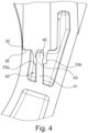
- the fiber channel body 25 is connected to the opening roller housing 17 in a locking manner, as can be seen from the Fig. 4 is evident.
- the opening roller housing 17 has a first means 40.
- the first means 40 is formed by a web 41 fixed on one side of the opening roller housing 17.
- the web 41 can be an integral part of the opening roller housing 17.
- the web 41 has a free end section 42 which is essentially concave in cross-section and has a taper 43. From the Fig. 4 it is clear that in the installed state the free end section 42 is positioned between the two tabs 33a, 33b. The tabs 33a, 33b have thickenings facing each other, which engage in complementary tapering of the free end section 42.
- the design of the first and second means 40, 34 creates a locking connection between the fiber channel body 25 and the opening roller housing 17.
- This design also has the advantage that the assembly of the fiber channel body 25 in or on the opening roller housing 17 is simplified. No additional means such as screws etc. are required to create a connection between the fiber channel body 25 and the opening roller housing 17.
- the one in the Fig. 2 The fiber channel body 25 shown has an insert 44.
- the insert 44 is preferably made of a wear-resistant material, in particular of a technical ceramic material.
- the fiber channel body 25 as such can also be made of plastic.
Landscapes
- Engineering & Computer Science (AREA)
- Mechanical Engineering (AREA)
- Textile Engineering (AREA)
- Spinning Or Twisting Of Yarns (AREA)
- Spinning Methods And Devices For Manufacturing Artificial Fibers (AREA)
Claims (7)
- Appareil à canal de guidage de fibres (15) pour un dispositif de filage à fibres libérées, comprenant un boîtier de cylindre ouvreur (17) comportant un logement (35) et un corps de canal de guidage de fibres (25) pouvant être fixé dans le logement (35) du boîtier de cylindre ouvreur (17), par l'intermédiaire duquel canal de guidage de fibres (26) des fibres individuelles, lesquelles sont peignées par un cylindre ouvreur (20) à partir d'un ruban de fibres d'alimentation, sont transportées de manière pneumatique vers un rotor de filage tournant un boîtier de rotor (2) pouvant être sollicité par une dépression,
caractérisé en ce que
le logement (35) présente des premiers moyens (40) et le corps de canal de guidage de fibres (25) présente des seconds moyens (34) pour former une liaison par encliquetage. - Appareil à canal de guidage de fibres (15) selon la revendication 1, caractérisé en ce que les premiers (40) et les seconds (34) moyens sont conçus de telle sorte que le corps de canal de guidage de fibres (25) peut être disposé dans le logement (35) sans pouvoir tourner par rapport à un axe longitudinal du canal de guidage de fibres (26).
- Appareil à canal de guidage de fibres (15) selon la revendication 1 ou 2, caractérisé en ce que les premiers (40) et/ou les seconds moyens (34) présentent au moins une section élastique.
- Appareil à canal de guidage de fibres (15) selon l'une des revendications précédentes, caractérisé en ce que le corps de canal de guidage de fibres (25) présente une zone d'entrée (30) tournée vers le cylindre ouvreur (20) et en ce que le corps de canal de guidage de fibres (25) présente, au niveau de son extrémité longitudinale tournée vers le boîtier de cylindre ouvreur (17), une surface frontale (32) fermant la zone d'entrée (30), et en ce que les seconds moyens (34) sont disposés sur la surface frontale (32).
- Appareil à canal de guidage de fibres (15) selon la revendication 4, caractérisé en ce que les seconds moyens (34) sont formés par deux languettes (33a, 33b) espacées sensiblement parallèlement l'une à l'autre et s'étendant depuis la surface frontale (32) du corps de canal de fibres (25) et les premiers moyens (40) sont formés par une barrette (41), dans lequel la barrette (41) est disposée au moins partiellement entre les languettes (33a ; 33b) dans un état d'encliquetage.
- Appareil à canal de guidage de fibres selon la revendication 5, caractérisé en ce que la barrette (41) présente une section d'extrémité libre (42) qui possède un rétrécissement (43), et en ce que les languettes (33a ; 33b) présentent des épaississements formés de manière correspondante.
- Appareil à canal de guidage de fibres selon l'une des revendications précédentes, caractérisé en ce que le corps de canal de guidage de fibres (25) est fabriqué au moins partiellement en une matière plastique.
Applications Claiming Priority (1)
| Application Number | Priority Date | Filing Date | Title |
|---|---|---|---|
| DE102018105075.5A DE102018105075A1 (de) | 2018-03-06 | 2018-03-06 | Faserleitkanaleinrichtung für eine Offenend-Spinnvorrichtung mit einer Rastverbindung |
Publications (2)
| Publication Number | Publication Date |
|---|---|
| EP3536835A1 EP3536835A1 (fr) | 2019-09-11 |
| EP3536835B1 true EP3536835B1 (fr) | 2024-11-20 |
Family
ID=65685230
Family Applications (1)
| Application Number | Title | Priority Date | Filing Date |
|---|---|---|---|
| EP19160486.7A Active EP3536835B1 (fr) | 2018-03-06 | 2019-03-04 | Dispositif de canal de guidage de fibres pour un dispositif de filage à extrémité ouverte doté d'une liaison d'encliquetage |
Country Status (3)
| Country | Link |
|---|---|
| EP (1) | EP3536835B1 (fr) |
| CN (1) | CN110230133B (fr) |
| DE (1) | DE102018105075A1 (fr) |
Families Citing this family (1)
| Publication number | Priority date | Publication date | Assignee | Title |
|---|---|---|---|---|
| DE102020106278A1 (de) * | 2020-03-09 | 2021-09-09 | Saurer Spinning Solutions Gmbh & Co. Kg | Vorrichtung zur Drehmomentübertragung |
Family Cites Families (13)
| Publication number | Priority date | Publication date | Assignee | Title |
|---|---|---|---|---|
| DE8304447U1 (de) * | 1983-02-18 | 1984-07-26 | Licentia Patent-Verwaltungs-Gmbh, 6000 Frankfurt | Staubsaugermundstueck zum absaugen von heizkoerpern |
| DE3923060A1 (de) * | 1989-07-13 | 1991-01-24 | Schubert & Salzer Maschinen | Offenend-spinnvorrichtung |
| DE19632888A1 (de) * | 1996-08-16 | 1998-02-19 | Rieter Ingolstadt Spinnerei | Offenend-Spinnvorrichtung und Verfahren zur Herstellung eines Transportkanals |
| DE10348710A1 (de) * | 2003-10-16 | 2005-05-12 | Saurer Gmbh & Co Kg | Faserleitkanal |
| DE102004005429A1 (de) * | 2004-02-04 | 2005-08-25 | Saurer Gmbh & Co. Kg | Faserleitkanal für eine Offenend-Spinnvorrichtung sowie Verfahren zum Herstellen eines Faserleitkanals |
| DE102005050102B4 (de) * | 2005-10-18 | 2018-04-05 | Rieter Ingolstadt Gmbh | Offenend-Spinnvorrichtung mit einem Faserkanal aus mehreren Kanalbauteilen |
| DE102007000621A1 (de) | 2007-11-05 | 2009-05-07 | Rieter Ingolstadt Gmbh | Faserleitkanalbauteil für eine Offenend-Spinnvorrichtung |
| DE102008050071A1 (de) * | 2008-10-01 | 2010-04-08 | Oerlikon Textile Gmbh & Co. Kg | Offenend-Rotorspinnvorrichtung |
| DE102009012045A1 (de) * | 2009-03-06 | 2010-09-09 | Oerlikon Textile Gmbh & Co. Kg | Offenend-Rotorspinnvorrichtung |
| DE102010044181A1 (de) * | 2010-11-19 | 2012-05-24 | Maschinenfabrik Rieter Ag | Faserkanaleinsatz |
| DE102011010925A1 (de) | 2011-02-11 | 2012-08-16 | Oerlikon Textile Gmbh & Co. Kg | Faserleitkanaleinrichtung für eine Offenend-Spinnvorrichtung |
| DE102011102883A1 (de) * | 2011-05-31 | 2012-12-06 | Oerlikon Textile Gmbh & Co. Kg | Offenend-Spinnvorrichtung |
| DE102013007432A1 (de) * | 2013-04-30 | 2014-10-30 | Saurer Germany Gmbh & Co. Kg | Faserführendes Textilmaschinen-Kunststoffteil, Textilmaschine mit faserführenden Funktionsbauteilen, Verfahren zum Herstellen eines faserführenden Textilmaschinen-Funktionsbauteils und Verwendung eines Kunststoffkörpers |
-
2018
- 2018-03-06 DE DE102018105075.5A patent/DE102018105075A1/de not_active Withdrawn
-
2019
- 2019-03-04 EP EP19160486.7A patent/EP3536835B1/fr active Active
- 2019-03-05 CN CN201910163429.5A patent/CN110230133B/zh not_active Expired - Fee Related
Also Published As
| Publication number | Publication date |
|---|---|
| DE102018105075A1 (de) | 2019-09-12 |
| CN110230133B (zh) | 2022-06-28 |
| CN110230133A (zh) | 2019-09-13 |
| EP3536835A1 (fr) | 2019-09-11 |
Similar Documents
| Publication | Publication Date | Title |
|---|---|---|
| EP2329066B1 (fr) | Groupe de filature a buse d'air comprenant un composant en forme de broche | |
| EP2403981B1 (fr) | Dispositif de filage à rotor à bout libre | |
| EP2828423B1 (fr) | Elément de support pour un dispositif de compression | |
| EP1156142A1 (fr) | Rotor de filage à bout libre | |
| EP0654551B1 (fr) | Métier à filer à bout libre | |
| EP2487282B1 (fr) | Dispositif de canal de guidage de fibres pour un métier à tisser à extrémité ouverte | |
| DE3402566A1 (de) | Vorrichtung zum oe-friktionsspinnen | |
| EP3110992B1 (fr) | Dispositif de compression à tambour d'aspiration | |
| EP1445359B1 (fr) | Adaptateur de plaque de canalisation pour un dispositif de filature à bout libre | |
| DE19712881B4 (de) | Offenend-Spinnvorrichtung | |
| EP3536835B1 (fr) | Dispositif de canal de guidage de fibres pour un dispositif de filage à extrémité ouverte doté d'une liaison d'encliquetage | |
| EP1367154B2 (fr) | Adaptateur de plaque de canalisation pour un dispositif de filature open-end | |
| EP1101845B1 (fr) | Palier pour un rotor de filage dans une machine de filature à bout ouvert | |
| DE4101315C2 (de) | Zuführ- und Auflöseeinrichtung für eine OE-Spinnvorrichtung | |
| EP1660708B1 (fr) | Plaque a rainure-guide pour un dispositif de filature a rotor a bout libere | |
| EP0926275B1 (fr) | Métier à filer à bout ouvert pour fabriquer des fils à torsion S ou Z | |
| EP1795633B1 (fr) | Machine à filer à bout ouvert comprennant un limiteur interchangeable de propagation de la torsion | |
| EP2599905B1 (fr) | Élément de couvercle d'un métier à tisser à extrémité ouverte destiné à fermer un boîtier de rotor à aspiration ouvert par l'arrière | |
| DE19712880A1 (de) | Faserbandauflöseeinrichtung | |
| DE10224589A1 (de) | Auflösewalzengehäuse | |
| DE4227884A1 (de) | Verfahren und Vorrichtung zum pneumatischen Zuführen von Fasern zu der Fasersammelfläche eines Offenend-Spinnelementes | |
| EP3690089B1 (fr) | Insert de guidage de fibres pour un boitier de cylindre ouvreur | |
| DE10359417B4 (de) | Faserleitkanal | |
| DE102013003284A1 (de) | Faserbandauflöseeinrichtung für eine Offenend-Spinnvorrichtung | |
| DE102008042163A1 (de) | Offenend-Spinnvorrichtung und Speisewalzenmotor |
Legal Events
| Date | Code | Title | Description |
|---|---|---|---|
| PUAI | Public reference made under article 153(3) epc to a published international application that has entered the european phase |
Free format text: ORIGINAL CODE: 0009012 |
|
| STAA | Information on the status of an ep patent application or granted ep patent |
Free format text: STATUS: THE APPLICATION HAS BEEN PUBLISHED |
|
| AK | Designated contracting states |
Kind code of ref document: A1 Designated state(s): AL AT BE BG CH CY CZ DE DK EE ES FI FR GB GR HR HU IE IS IT LI LT LU LV MC MK MT NL NO PL PT RO RS SE SI SK SM TR |
|
| AX | Request for extension of the european patent |
Extension state: BA ME |
|
| STAA | Information on the status of an ep patent application or granted ep patent |
Free format text: STATUS: REQUEST FOR EXAMINATION WAS MADE |
|
| 17P | Request for examination filed |
Effective date: 20200311 |
|
| RBV | Designated contracting states (corrected) |
Designated state(s): AL AT BE BG CH CY CZ DE DK EE ES FI FR GB GR HR HU IE IS IT LI LT LU LV MC MK MT NL NO PL PT RO RS SE SI SK SM TR |
|
| STAA | Information on the status of an ep patent application or granted ep patent |
Free format text: STATUS: EXAMINATION IS IN PROGRESS |
|
| 17Q | First examination report despatched |
Effective date: 20220516 |
|
| GRAP | Despatch of communication of intention to grant a patent |
Free format text: ORIGINAL CODE: EPIDOSNIGR1 |
|
| STAA | Information on the status of an ep patent application or granted ep patent |
Free format text: STATUS: GRANT OF PATENT IS INTENDED |
|
| INTG | Intention to grant announced |
Effective date: 20240627 |
|
| GRAS | Grant fee paid |
Free format text: ORIGINAL CODE: EPIDOSNIGR3 |
|
| GRAA | (expected) grant |
Free format text: ORIGINAL CODE: 0009210 |
|
| STAA | Information on the status of an ep patent application or granted ep patent |
Free format text: STATUS: THE PATENT HAS BEEN GRANTED |
|
| AK | Designated contracting states |
Kind code of ref document: B1 Designated state(s): AL AT BE BG CH CY CZ DE DK EE ES FI FR GB GR HR HU IE IS IT LI LT LU LV MC MK MT NL NO PL PT RO RS SE SI SK SM TR |
|
| REG | Reference to a national code |
Ref country code: GB Ref legal event code: FG4D Free format text: NOT ENGLISH |
|
| REG | Reference to a national code |
Ref country code: CH Ref legal event code: EP |
|
| REG | Reference to a national code |
Ref country code: DE Ref legal event code: R096 Ref document number: 502019012493 Country of ref document: DE |
|
| REG | Reference to a national code |
Ref country code: IE Ref legal event code: FG4D Free format text: LANGUAGE OF EP DOCUMENT: GERMAN |
|
| REG | Reference to a national code |
Ref country code: LT Ref legal event code: MG9D |
|
| REG | Reference to a national code |
Ref country code: NL Ref legal event code: MP Effective date: 20241120 |
|
| PG25 | Lapsed in a contracting state [announced via postgrant information from national office to epo] |
Ref country code: PT Free format text: LAPSE BECAUSE OF FAILURE TO SUBMIT A TRANSLATION OF THE DESCRIPTION OR TO PAY THE FEE WITHIN THE PRESCRIBED TIME-LIMIT Effective date: 20250320 Ref country code: HR Free format text: LAPSE BECAUSE OF FAILURE TO SUBMIT A TRANSLATION OF THE DESCRIPTION OR TO PAY THE FEE WITHIN THE PRESCRIBED TIME-LIMIT Effective date: 20241120 Ref country code: IS Free format text: LAPSE BECAUSE OF FAILURE TO SUBMIT A TRANSLATION OF THE DESCRIPTION OR TO PAY THE FEE WITHIN THE PRESCRIBED TIME-LIMIT Effective date: 20250320 |
|
| PG25 | Lapsed in a contracting state [announced via postgrant information from national office to epo] |
Ref country code: NL Free format text: LAPSE BECAUSE OF FAILURE TO SUBMIT A TRANSLATION OF THE DESCRIPTION OR TO PAY THE FEE WITHIN THE PRESCRIBED TIME-LIMIT Effective date: 20241120 Ref country code: FI Free format text: LAPSE BECAUSE OF FAILURE TO SUBMIT A TRANSLATION OF THE DESCRIPTION OR TO PAY THE FEE WITHIN THE PRESCRIBED TIME-LIMIT Effective date: 20241120 |
|
| PG25 | Lapsed in a contracting state [announced via postgrant information from national office to epo] |
Ref country code: BG Free format text: LAPSE BECAUSE OF FAILURE TO SUBMIT A TRANSLATION OF THE DESCRIPTION OR TO PAY THE FEE WITHIN THE PRESCRIBED TIME-LIMIT Effective date: 20241120 |
|
| PG25 | Lapsed in a contracting state [announced via postgrant information from national office to epo] |
Ref country code: ES Free format text: LAPSE BECAUSE OF FAILURE TO SUBMIT A TRANSLATION OF THE DESCRIPTION OR TO PAY THE FEE WITHIN THE PRESCRIBED TIME-LIMIT Effective date: 20241120 |
|
| PG25 | Lapsed in a contracting state [announced via postgrant information from national office to epo] |
Ref country code: NO Free format text: LAPSE BECAUSE OF FAILURE TO SUBMIT A TRANSLATION OF THE DESCRIPTION OR TO PAY THE FEE WITHIN THE PRESCRIBED TIME-LIMIT Effective date: 20250220 |
|
| PG25 | Lapsed in a contracting state [announced via postgrant information from national office to epo] |
Ref country code: LV Free format text: LAPSE BECAUSE OF FAILURE TO SUBMIT A TRANSLATION OF THE DESCRIPTION OR TO PAY THE FEE WITHIN THE PRESCRIBED TIME-LIMIT Effective date: 20241120 Ref country code: GR Free format text: LAPSE BECAUSE OF FAILURE TO SUBMIT A TRANSLATION OF THE DESCRIPTION OR TO PAY THE FEE WITHIN THE PRESCRIBED TIME-LIMIT Effective date: 20250221 |
|
| PG25 | Lapsed in a contracting state [announced via postgrant information from national office to epo] |
Ref country code: PL Free format text: LAPSE BECAUSE OF FAILURE TO SUBMIT A TRANSLATION OF THE DESCRIPTION OR TO PAY THE FEE WITHIN THE PRESCRIBED TIME-LIMIT Effective date: 20241120 |
|
| PG25 | Lapsed in a contracting state [announced via postgrant information from national office to epo] |
Ref country code: RS Free format text: LAPSE BECAUSE OF FAILURE TO SUBMIT A TRANSLATION OF THE DESCRIPTION OR TO PAY THE FEE WITHIN THE PRESCRIBED TIME-LIMIT Effective date: 20250220 |
|
| PG25 | Lapsed in a contracting state [announced via postgrant information from national office to epo] |
Ref country code: SM Free format text: LAPSE BECAUSE OF FAILURE TO SUBMIT A TRANSLATION OF THE DESCRIPTION OR TO PAY THE FEE WITHIN THE PRESCRIBED TIME-LIMIT Effective date: 20241120 |
|
| PG25 | Lapsed in a contracting state [announced via postgrant information from national office to epo] |
Ref country code: DK Free format text: LAPSE BECAUSE OF FAILURE TO SUBMIT A TRANSLATION OF THE DESCRIPTION OR TO PAY THE FEE WITHIN THE PRESCRIBED TIME-LIMIT Effective date: 20241120 |
|
| PG25 | Lapsed in a contracting state [announced via postgrant information from national office to epo] |
Ref country code: EE Free format text: LAPSE BECAUSE OF FAILURE TO SUBMIT A TRANSLATION OF THE DESCRIPTION OR TO PAY THE FEE WITHIN THE PRESCRIBED TIME-LIMIT Effective date: 20241120 |
|
| PG25 | Lapsed in a contracting state [announced via postgrant information from national office to epo] |
Ref country code: RO Free format text: LAPSE BECAUSE OF FAILURE TO SUBMIT A TRANSLATION OF THE DESCRIPTION OR TO PAY THE FEE WITHIN THE PRESCRIBED TIME-LIMIT Effective date: 20241120 |
|
| PG25 | Lapsed in a contracting state [announced via postgrant information from national office to epo] |
Ref country code: SK Free format text: LAPSE BECAUSE OF FAILURE TO SUBMIT A TRANSLATION OF THE DESCRIPTION OR TO PAY THE FEE WITHIN THE PRESCRIBED TIME-LIMIT Effective date: 20241120 |
|
| REG | Reference to a national code |
Ref country code: DE Ref legal event code: R097 Ref document number: 502019012493 Country of ref document: DE |
|
| PG25 | Lapsed in a contracting state [announced via postgrant information from national office to epo] |
Ref country code: SE Free format text: LAPSE BECAUSE OF FAILURE TO SUBMIT A TRANSLATION OF THE DESCRIPTION OR TO PAY THE FEE WITHIN THE PRESCRIBED TIME-LIMIT Effective date: 20241120 |
|
| PLBE | No opposition filed within time limit |
Free format text: ORIGINAL CODE: 0009261 |
|
| STAA | Information on the status of an ep patent application or granted ep patent |
Free format text: STATUS: NO OPPOSITION FILED WITHIN TIME LIMIT |
|
| REG | Reference to a national code |
Ref country code: DE Ref legal event code: R119 Ref document number: 502019012493 Country of ref document: DE |
|
| PG25 | Lapsed in a contracting state [announced via postgrant information from national office to epo] |
Ref country code: MC Free format text: LAPSE BECAUSE OF FAILURE TO SUBMIT A TRANSLATION OF THE DESCRIPTION OR TO PAY THE FEE WITHIN THE PRESCRIBED TIME-LIMIT Effective date: 20241120 |
|
| 26N | No opposition filed |
Effective date: 20250821 |
|
| PG25 | Lapsed in a contracting state [announced via postgrant information from national office to epo] |
Ref country code: CZ Free format text: LAPSE BECAUSE OF NON-PAYMENT OF DUE FEES Effective date: 20250304 |
|
| REG | Reference to a national code |
Ref country code: CH Ref legal event code: H13 Free format text: ST27 STATUS EVENT CODE: U-0-0-H10-H13 (AS PROVIDED BY THE NATIONAL OFFICE) Effective date: 20251023 |
|
| PG25 | Lapsed in a contracting state [announced via postgrant information from national office to epo] |
Ref country code: LU Free format text: LAPSE BECAUSE OF NON-PAYMENT OF DUE FEES Effective date: 20250304 |
|
| GBPC | Gb: european patent ceased through non-payment of renewal fee |
Effective date: 20250304 |
|
| REG | Reference to a national code |
Ref country code: BE Ref legal event code: MM Effective date: 20250331 |
|
| PG25 | Lapsed in a contracting state [announced via postgrant information from national office to epo] |
Ref country code: DE Free format text: LAPSE BECAUSE OF NON-PAYMENT OF DUE FEES Effective date: 20251001 |
|
| PG25 | Lapsed in a contracting state [announced via postgrant information from national office to epo] |
Ref country code: GB Free format text: LAPSE BECAUSE OF NON-PAYMENT OF DUE FEES Effective date: 20250304 |
|
| PG25 | Lapsed in a contracting state [announced via postgrant information from national office to epo] |
Ref country code: FR Free format text: LAPSE BECAUSE OF NON-PAYMENT OF DUE FEES Effective date: 20250331 Ref country code: IT Free format text: LAPSE BECAUSE OF NON-PAYMENT OF DUE FEES Effective date: 20250304 |
|
| PG25 | Lapsed in a contracting state [announced via postgrant information from national office to epo] |
Ref country code: BE Free format text: LAPSE BECAUSE OF NON-PAYMENT OF DUE FEES Effective date: 20250331 |
|
| PG25 | Lapsed in a contracting state [announced via postgrant information from national office to epo] |
Ref country code: CH Free format text: LAPSE BECAUSE OF NON-PAYMENT OF DUE FEES Effective date: 20250331 |
|
| PG25 | Lapsed in a contracting state [announced via postgrant information from national office to epo] |
Ref country code: IE Free format text: LAPSE BECAUSE OF NON-PAYMENT OF DUE FEES Effective date: 20250304 |