EP2828484B2 - Aube de turbine - Google Patents
Aube de turbine Download PDFInfo
- Publication number
- EP2828484B2 EP2828484B2 EP13714573.6A EP13714573A EP2828484B2 EP 2828484 B2 EP2828484 B2 EP 2828484B2 EP 13714573 A EP13714573 A EP 13714573A EP 2828484 B2 EP2828484 B2 EP 2828484B2
- Authority
- EP
- European Patent Office
- Prior art keywords
- side wall
- wall
- suction
- pressure
- leading edge
- Prior art date
- Legal status (The legal status is an assumption and is not a legal conclusion. Google has not performed a legal analysis and makes no representation as to the accuracy of the status listed.)
- Active
Links
Images


Classifications
-
- F—MECHANICAL ENGINEERING; LIGHTING; HEATING; WEAPONS; BLASTING
- F01—MACHINES OR ENGINES IN GENERAL; ENGINE PLANTS IN GENERAL; STEAM ENGINES
- F01D—NON-POSITIVE DISPLACEMENT MACHINES OR ENGINES, e.g. STEAM TURBINES
- F01D5/00—Blades; Blade-carrying members; Heating, heat-insulating, cooling or antivibration means on the blades or the members
- F01D5/12—Blades
- F01D5/14—Form or construction
- F01D5/18—Hollow blades, i.e. blades with cooling or heating channels or cavities; Heating, heat-insulating or cooling means on blades
- F01D5/186—Film cooling
-
- F—MECHANICAL ENGINEERING; LIGHTING; HEATING; WEAPONS; BLASTING
- F01—MACHINES OR ENGINES IN GENERAL; ENGINE PLANTS IN GENERAL; STEAM ENGINES
- F01D—NON-POSITIVE DISPLACEMENT MACHINES OR ENGINES, e.g. STEAM TURBINES
- F01D5/00—Blades; Blade-carrying members; Heating, heat-insulating, cooling or antivibration means on the blades or the members
- F01D5/12—Blades
- F01D5/14—Form or construction
- F01D5/18—Hollow blades, i.e. blades with cooling or heating channels or cavities; Heating, heat-insulating or cooling means on blades
- F01D5/187—Convection cooling
-
- F—MECHANICAL ENGINEERING; LIGHTING; HEATING; WEAPONS; BLASTING
- F05—INDEXING SCHEMES RELATING TO ENGINES OR PUMPS IN VARIOUS SUBCLASSES OF CLASSES F01-F04
- F05C—INDEXING SCHEME RELATING TO MATERIALS, MATERIAL PROPERTIES OR MATERIAL CHARACTERISTICS FOR MACHINES, ENGINES OR PUMPS OTHER THAN NON-POSITIVE-DISPLACEMENT MACHINES OR ENGINES
- F05C2251/00—Material properties
- F05C2251/02—Elasticity
-
- F—MECHANICAL ENGINEERING; LIGHTING; HEATING; WEAPONS; BLASTING
- F05—INDEXING SCHEMES RELATING TO ENGINES OR PUMPS IN VARIOUS SUBCLASSES OF CLASSES F01-F04
- F05D—INDEXING SCHEME FOR ASPECTS RELATING TO NON-POSITIVE-DISPLACEMENT MACHINES OR ENGINES, GAS-TURBINES OR JET-PROPULSION PLANTS
- F05D2250/00—Geometry
- F05D2250/70—Shape
- F05D2250/71—Shape curved
-
- F—MECHANICAL ENGINEERING; LIGHTING; HEATING; WEAPONS; BLASTING
- F05—INDEXING SCHEMES RELATING TO ENGINES OR PUMPS IN VARIOUS SUBCLASSES OF CLASSES F01-F04
- F05D—INDEXING SCHEME FOR ASPECTS RELATING TO NON-POSITIVE-DISPLACEMENT MACHINES OR ENGINES, GAS-TURBINES OR JET-PROPULSION PLANTS
- F05D2300/00—Materials; Properties thereof
- F05D2300/50—Intrinsic material properties or characteristics
- F05D2300/501—Elasticity
Definitions
- Turbine blades of the above-mentioned type are heat-resistant components which are used in particular within turbine stages of gas turbine arrangements and, in the form of guide or rotor blades, are exposed to the hot gases escaping directly from the combustion chamber.
- the heat resistance of such turbine blades is due, on the one hand, to the use of heat-resistant materials and, on the other hand, to a highly efficient cooling of the turbine blades directly exposed to the hot gases, which have corresponding cavities for the purpose of continuous flow and exposure to a coolant, preferably cooling air, which are connected to a coolant feed system of the gas turbine arrangement, which provides cooling air for cooling all heat-exposed gas turbine components during gas turbine operation, in particular the turbine blades.
- Conventional turbine blades have a blade root, which is directly or indirectly connected to the blade leaf in the radial direction.
- the blade leaf has a concave pressure side wall and a convex suction side wall, which are integrally connected in the area of the blade leading edge and between which a gap is defined, which is supplied with cooling air from the blade root for cooling purposes.
- the term "radially” refers to the turbine blade extension in the assembled state within the gas turbine arrangement, which is oriented radially to the axis of rotation of the rotor unit.
- the gap is provided with radially extending partition walls, which each delimit cavities oriented radially within the blade leaf, some of which have fluidic connections.
- passage openings are provided in the suction or pressure side wall, in the area of the turbine blade leading and/or trailing edge or at the turbine blade tip so that the cooling air can escape to the outside into the hot gas channel of the turbine stage.
- a gas turbine blade optimized for cooling purposes is the EP 1 319 803 A2 which provides a large number of radially oriented cooling channel cavities within the turbine blade, each of which is fluidically connected in a meandering shape and through which more or less cooling air flows depending on the blade area subjected to different levels of heat.
- the area of the blade leading edge which experiences the greatest flow and heat exposure of the hot gases, must be cooled in a particularly efficient manner.
- a cavity extends along the inner wall of the blade leading edge, which is delimited by the suction and pressure side walls, which unite at the blade leading edge, and by an intermediate wall, which connects the suction and pressure sides to one another on the inner wall, and which is fed with cooling air from the blade root side.
- the cooling air flowing through the cavity usually reaches the outside in the area of the blade tip.
- structures that swirl the cooling air flow are also provided along the wall areas enclosing the cavity.
- a cavity runs along the leading edge of the blade, which is delimited on the one hand by the suction and pressure side walls, which unite at the leading edge of the blade, and by an intermediate wall, which rigidly connects the suction and pressure side walls within the blade.
- the cavity running along the leading edge of the blade is fed with cooling air, which enters the cavity exclusively through cooling channel openings provided within the intermediate wall.
- the straight intermediate wall is provided with a large number of individual through-channels in its radial longitudinal extension, through which cooling air from an adjacent radially running cooling channel along the blade enters in the form of impingement cooling in the direction of the leading edge of the blade within the cavity described above.
- film cooling openings are provided along the leading edge of the blade, directed towards the suction and pressure side outer walls, through which the cooling air introduced within the cavity is discharged to the pressure and suction side outer walls, forming a film cooling.
- Turbine blades which are designed for the purpose of optimised heat resistance, particularly in the area of Blade leading edges have the cooling measures explained above, but often show signs of fatigue in the blade leading edge area along the pressure and suction side walls, which in the final stage appear as cracks.
- the reason for such cracks is the occurrence of thermo-mechanical stresses within the suction and pressure side walls in the blade leading edge area, which arise from high temperature differences between the blade leading edge exposed to hot gas and the inner wall areas of the blade exposed to cooling air.
- temperature differences of around 1000°C can occur between the blade leading edge exposed to hot gas and the intermediate and inner wall sections exposed to cooling air. It is obvious that with such large temperature differences, considerable thermo-mechanical stresses occur within the suction side and pressure side walls along the blade leading edge, which lead to considerable material stresses, as mentioned above.
- the EP 0 806 546 A1 discloses a turbine blade with a ceramic leading edge insert, which is placed on the leading edge of the blade profile and is impingement air cooled.
- the disclosure is based on the object of developing a turbine blade according to claim 1 for a rotary fluid machine with a blade that is delimited by a concave pressure side wall and a convex suction side wall, which are connected in the region of a blade leading edge that can be assigned to the blade and enclose a cavity that extends the length of the blade leading edge, which is delimited on the inside by the pressure and suction side walls in the region of the blade leading edge and by an intermediate wall that extends in the longitudinal direction to the blade leading edge and connects the suction and pressure side walls on the inside, in such a way that the fatigue phenomena caused by temperature differences in the region of the blade leading edge are to be reduced or completely avoided in order to improve the service life of the turbine blades that are exposed to high levels of heat.
- the measures required for this should not impair the cooling measures known per se as far as possible, but rather improve and support them.
- the measures required for this should also not require any costly or complex manufacturing expenditure.
- a turbine blade according to the solution for a rotary fluid machine has a blade that is delimited by a concave pressure side wall and a convex suction side wall. These walls are connected in the area of a blade leading edge that can be assigned to the blade and enclose a cavity that extends in the longitudinal extension of the blade leading edge and is delimited internally by the pressure and suction side wall in the area of the blade leading edge and by an intermediate wall that extends longitudinally to the blade leading edge and connects the suction and pressure side walls internally.
- This intermediate wall and the suction and/or pressure side wall are a continuous part. This is typically manufactured as a cast part.
- the disclosed turbine blade is characterized in that the intermediate wall in the connection area to the suction and/or pressure side wall has a perforation at least in sections in order to increase the elasticity.
- Perforation is to be understood as a large number of holes. These are typically arranged along a line. Typically, this line is straight at least in sections. For example, three or more holes can be arranged along a straight line. In particular, this increases the elasticity of the partition wall. Due to the elastic connection area, the partition wall has a less stiffening effect on the entire blade, so that the tension between the pressure and suction side walls is also reduced.
- the connection area of the partition wall to the suction and/or pressure side wall is referred to here as the area of the partition wall adjacent to the suction and/or pressure side wall.
- connection area can extend up to a quarter of the distance between the suction and pressure side walls. Typically, the connection area extends over a distance that is smaller than the thickness of the partition wall or smaller than one to two times the thickness of the partition wall. According to one embodiment, the connection area is limited to a curve or groove in the transition from the partition wall to the suction and/or pressure side wall. According to another embodiment, the connection area is limited to an area from the side wall that corresponds to twice the radius of the curve or groove in the transition from the partition wall to the suction and/or pressure side wall.
- the partition wall immediately downstream of the blade leading edge which together with the inner walls of the pressure and suction side wall delimits the cavity running along the blade leading edge, is modified according to the solution in such a way that the partition wall or the connecting area of the partition wall experiences elasticity, whereby the thermally induced expansion and contraction tendencies of the suction and pressure side wall areas along the blade leading edge can be at least partially yielded to.
- the partition wall has a perforation at least in one connecting area to the side wall, through which the elasticity described above can be achieved.
- the perforation comprises a series of cylindrical holes.
- the perforation comprises a series of elongated holes or slots, the longer side of which extends parallel to the adjacent suction or pressure side wall.
- connection between the intermediate wall and the side wall results in relatively thick accumulations of material whose surface-to-volume ratio is much smaller than in a free wall section.
- the connection also impedes the flow of the walls, so that the temperature of the blade material in the connection area changes more slowly in the event of transient changes in the hot gas or cooling air temperatures than the material temperatures in a free wall section. This leads to additional thermal stresses, which are reduced by the perforation.
- connection area between the partition wall and the suction and/or pressure side wall is even designed with a curve or groove.
- This groove is a manufacturing process for cast blades. On the one hand, it reduces the concentration of stress at the wall connection, but on the other hand, the groove increases the accumulation of material in the connection area between the partition wall and the suction and/or pressure side wall.
- the perforation in the connection area improves the heat transfer on the inside of the walls so that transient temperature changes can be better followed.
- the perforation runs at least partially through the groove.
- the partition wall has at least one curved wall section extending from the suction side wall to the pressure side wall or vice versa, deviating from a straight wall course. This curvature increases the elasticity, so that a flexible partition wall is produced, particularly in combination with the perforated connection area of the partition wall.
- the turbine blade has a perforation at least in sections at the base of the "V" or “U” shaped cross-section of the intermediate wall, which runs parallel to the perforation of the connection area in order to increase the elasticity.
- this results in a hinge-like structure for the intermediate wall between the two legs of the "V” or “U” shaped cross-section, which enables the legs to rotate around the perforations and thus ensures compensation for changes in the mutual distance between the pressure and suction side walls.
- the intermediate wall allows the mutual distance between the pressure and suction side walls in the blade leading edge area to adjust depending on the temperature level without harmful mechanical stresses occurring within the pressure and suction side walls, particularly in the connection area to the inner intermediate wall.
- a preferred embodiment provides for the partition wall to be designed at least in some areas with an equal or preferably smaller partition wall thickness compared to the wall thicknesses of the suction and pressure side walls in the blade leading edge area. It is not necessarily necessary for the partition wall to have a constant wall thickness along its entire wall cross-section. In this way, the partition wall thickness, elasticity of the perforated connection area and the curvature behavior of the partition wall can be optimally coordinated with one another in such a way that a particularly suitable wall elasticity can be achieved. If particularly high wall elasticities are to be achieved, particularly strongly curved and/or suitably thin wall sections along the partition wall are suitable.
- the solution-based measure of an intermediate wall with a perforated connection area is also not necessarily limited to the intermediate wall directly facing the blade leading edge. It is of course also possible to design other intermediate walls provided within the blade profile with perforations or perforations and curved in accordance with the solution in order to be able to give way to thermally induced shrinkage or expansion effects relating to the pressure and suction side walls without stress. It has proven particularly advantageous that the "V" or "U”-shaped wall curvature of the intermediate wall directly facing the blade leading edge is designed and arranged in such a way that the convex wall side of the "V" or "U”-shaped wall section faces the area of the blade leading edge.
- the curved contour of the intermediate wall which extends from the suction to the pressure side wall or in the opposite direction, in such a way that the convex wall side of the intermediate wall facing the blade leading edge is designed and arranged largely parallel to the suction and pressure side wall that delimits the cavity and is connected to the blade leading edge.
- impingement cooling it is possible to direct impingement cooling air flows through passage channels introduced within the intermediate wall to specific inner wall areas in the blade leading edge area. In this way, temperature-related material stresses can be effectively counteracted by optimized cooling of the blade leading edge area.
- a row of holes is considered to be a perforation in which the proportion of hole lengths in the perforation direction is at least 30% of the total length of the perforated area.
- the proportion of hole lengths is at least 50% of the total length of the perforated area. This is achieved, for example, by a series of cylindrical holes, each spaced twice the diameter. In particular, in designs with elongated holes or slots, a proportion of hole lengths can exceed 70% of the total length of the perforated area.
- connection area of the partition wall to the pressure or suction side wall comprises, for example, up to 20% of the wall distance between the two side walls.
- connection area extends one or two wall thicknesses of the partition wall in the connection direction of the partition wall.
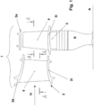
- Fig. 1 are a schematic representation of a Guide vane 2 and a rotor blade 3 are shown as they are arranged in a turbine stage 1 (not illustrated in more detail) along a row of guide vanes and rotor blades. It is assumed that the guide vane 2 and the rotor blade 3 come into contact with a hot gas flow H which, in the illustration, flows over the respective blades 4 of the guide vane 2 and the rotor blade 3 from left to right.
- a hot gas flow H which, in the illustration, flows over the respective blades 4 of the guide vane 2 and the rotor blade 3 from left to right.
- the blades 4 of the guide vanes and rotor blades 2, 3 protrude into the hot gas channel of the turbine stage 1 of a gas turbine arrangement, which is delimited by radially inner shrouds 2i, 3i and by the radially outer shrouds 2a of the guide vanes 2 and radially outer heat accumulation segments 3a.
- the rotor blade 3 is mounted on a rotor unit R (not shown in more detail), which is mounted so as to be rotatable about an axis of rotation A.
- Fig. 2 is a cross-sectional view of a guide or rotor blade, which extends along a Fig. 1
- the typical blade profile of a turbine guide vane or turbine rotor blade is characterized by an aerodynamically profiled blade 4, which is delimited on both sides by a convex suction side wall 7 and a concave pressure side wall 6.
- the convex suction side wall 7 and the concave pressure side wall 6 are joined together in one piece in the area of the blade leading edge 5, which, as already explained at the beginning, is directly exposed to the hot gas flow passing through the turbine stage of a gas turbine arrangement. It is obvious that the turbine blade area along the blade leading edge 5 is subjected to particularly high thermal stress.
- radially oriented cavities 9, 10, 11 etc. are provided within the blade 4, which are flushed with cooling air.
- the individual cavities 9, 10, 11 etc. are separated from one another by partition walls 8, 12, 13 etc.
- the individual cooling channels 9, 10, 11 etc. communicate with one another.
- the foremost intermediate wall 8 in the connection area to the suction 7 and/or pressure side walls 6 is provided with a perforation 16 at least in sections.
- Embodiments of perforations 16 are shown in the Fig. 3a, b and c shown.
- a first embodiment is shown in the Fig. 3a shown.
- One perforation 16 is provided in the connection area of the intermediate wall 8 to the suction and pressure side walls 6, 7.
- the perforations in the example shown are a series of cylindrical holes 18 that are arranged parallel to the suction and pressure side walls 6, 7.
- the perforation 16 on the pressure side wall 6 runs in the example only over a section of the intermediate wall 8.
- a second embodiment is shown in the Fig. 3b shown.
- One perforation 16 is provided in the connection area of the intermediate wall 8 to the suction and pressure side walls 6, 7.
- the perforations in this example are a series of elongated holes 19 which are arranged parallel to the suction and pressure side walls 6, 7 and whose longer side extends parallel to the adjacent suction 7 or pressure side wall 6.
- a central perforation 20 is also provided, which runs parallel to the suction and pressure side walls 6, 7 in the middle of the intermediate wall 8. Together with the perforations 16 in the connection area to the suction and pressure side walls 6, 7, a two-part intermediate wall 8 is formed, which can be flexibly folded together.
- FIG. 4a illustrated detailed embodiment, which shows the blade profile in the blade leading edge area.
- the Fig. 4a shows a perforation 16 in the connection area of the suction side wall 7 and in the connection area of the pressure side wall 6.
- the main direction of the material expansion or shrinkage tendency 21 of the side walls 6, 7 runs in the example essentially parallel to the extension of the intermediate wall 8.
- FIG. 1 , 2 , 3 and 4a an embodiment with a curved partition wall 8 is shown.
- the partition wall 8 has a U-shaped wall cross-section which is integrally connected to the inside of both the suction side wall 6 and the pressure side wall 7.
- the U-shaped wall design of the partition wall 8 gives the blade profile area additional elastic deformability in such a way that the thermally induced material expansion or shrinkage tendency of the suction and pressure side walls can be accommodated by the wall distance w not being fixed, as before, but variable within certain limits which are determined by the shape and curvature elasticity of the partition wall 8 and the elasticity of the perforation 16.
- FIG. 4c an embodiment with an additional central perforation 20 is shown in detail.
- This divides the intermediate wall 8 into two legs, which run towards each other at an angle starting from the connection area to the side walls 6, 7, whereby the angle can be flexibly changed by the central perforation 20 and thus expansion-related changes in the distance between the pressure and suction side walls can be easily compensated.
- Cooling air passes out of the cavity 9 through the film cooling holes 14 and forms a cooling air film that rests on the surface of the suction 6 and pressure side outer wall 7.
- the U-shaped intermediate wall 8, which is integrally connected on both sides to the inner wall of the suction side wall 7 and the pressure side wall 6, preferably has a convex wall profile that faces the blade leading edge 5 and is largely parallel to the suction side wall 7 and the pressure side wall 6 that delimit the cavity 9 and are integrally connected to the blade leading edge 5.
- the cooling air at least partially passes through the perforations 16 and central perforation 20 into the front cavity 9.
- the intermediate wall has perforations 16 in the connection areas to the suction side wall 7 and pressure side wall 6.
- it also has cooling air passage channels 15a, b, c, which serve for impingement air cooling of the inner wall side of the blade wall leading edge.
- the passage channels 15a, b, c can be divided into at least three groups with regard to their passage channel longitudinal extent and the flow direction predetermined thereby.
- a first group of passage channels 15a is characterized by a flow direction directed towards the suction side wall 7
- a second group of passage channels 15b is characterized by a flow direction directed towards the blade leading edge
- a third group of passage channels 15c is characterized by a flow direction directed towards the pressure side wall 6.
- the passage channels 15a, 15b and 15c are distributed along the entire radial extent in the intermediate wall 8 and thus ensure effective and individual cooling of the leading edge area of the turbine blade. Of course, further passage channels can be attached to the intermediate wall 8 for the purpose of optimized impact cooling.
- impingement air cooling can be combined with central perforation.
- impingement air cooling holes have a larger diameter, e.g. twice as large as perforation holes.
Landscapes
- Engineering & Computer Science (AREA)
- Mechanical Engineering (AREA)
- General Engineering & Computer Science (AREA)
- Turbine Rotor Nozzle Sealing (AREA)
Claims (11)
- Aube de turbine pour une turbomachine rotative, la pale de turbine comprenant une pale (4), qui est délimitée par une paroi concave côté pression (6) et une paroi convexe côté aspiration (7), qui sont reliées au niveau d'une arête avant de pale (5) pouvant correspondre à la pale (4) et qui forment une cavité (9), s'étendant dans l'extension longitudinale de l'arête avant de la pale (5), qui est délimitée, à l'intérieur des parois, par les parois côté pression (6) et côté aspiration (7) au niveau de l'arête avant de la pale (5) ainsi que par une paroi intermédiaire (8) s'étendant dans la direction longitudinale vers l'arête avant de la pale (5), reliant à l'intérieur des parois les parois côté aspiration (7) et côté pression (6), l'aube de turbine comprenant, dans la transition entre la paroi intermédiaire (8) et les parois côté aspiration (7) et/ou côté pression (6), un arrondi ou une gorge (17),
caractérisée en ce que la paroi intermédiaire (8) comprend, dans une partie de raccordement aux parois côté aspiration (7) et/ou côté pression (6) au moins à certains endroits une perforation (16) afin d'augmenter l'élasticité de la paroi intermédiaire dans la partie de raccordement, la partie de raccordement étant limitée à une partie à partir de la paroi côté aspiration (7) et/ou côté pression (6), qui correspond au double du rayon de l'arrondi ou de la gorge (17) ;en ce que la paroi intermédiaire (8) comprend, dans l'extension de la paroi côté aspiration (7) à la paroi côté pression (6) ou inversement, au moins une portion de paroi réalisée de manière courbe, s'écartant d'un tracé de paroi linéaire et en ce que l'au moins une portion de paroi courbe est réalisée de façon à ce que la portion de paroi présente une élasticité due à sa courbure en direction de l'extension de la paroi intermédiaire (8) de la paroi côté aspiration (7) vers la paroi côté pression (6) ou inversement;en ce que, dans la paroi intermédiaire (8), sont prévus des canaux de passage (15) pour un refroidissement par impact de la paroi côté aspiration (7) et de la paroi côté pression (6) reliées à l'arête avant de l'aube (5). - Aube de turbine selon la revendication 1, caractérisée en ce que la perforation (16) comprend une rangée de trous cylindriques (18).
- Aube de turbine selon la revendication 1, caractérisée en ce que la perforation comprend une rangée de trous allongés (19) ou de fentes dont le côté le plus long est parallèle à la paroi côté aspiration (7) et/ou côté pression (6) adjacente.
- Aube de turbine selon l'une des revendications 1 à 3,
caractérisée en ce que la partie de raccordement de la paroi intermédiaire (8) aux parois côté aspiration (7) et/ou côté pression (6) comprend une gorge (17) et en ce que la perforation (16) s'étend au moins partiellement à travers la gorge (17). - Aube de turbine selon l'une des revendications 1 à 4,caractérisée en ce que la paroi intermédiaire (8) comprend un côté de paroi opposé à la cavité (9), qui délimite au moins une autre cavité (10) avec les parois côté aspiration (7) et côté pression (6),et en ce que les cavités (9, 10) sont des canaux de refroidissement dans lequel un produit de refroidissement peut être introduit.
- Aube de turbine selon la revendication 5,
caractérisée en ce que les ouvertures de la perforation (16) sont réalisées parallèlement à la surface de la paroi côté aspiration (7) respectivement paroi côté pression (6) dans la partie de raccordement de la paroi intermédiaire (8) et, pendant le fonctionnement, l'air de refroidissement s'écoule à travers ces ouvertures d'une cavité (10) à l'autre cavité (9) et un jet de sortie de l'ouverture correspondante s'étendant de manière tangentielle par rapport à la paroi interne de la paroi côté aspiration (7) respectivement paroi côté pression (6) correspondante. - Aube de turbine selon l'une des revendications 1 à 6,
caractérisée en ce que l'au moins une portion de paroi réalisée de manière courbe est réalisée en forme de v ou en forme de u dans une section transversale coupant l'arête avant de l'aube (5). - Aube de turbine selon la revendication 7,
caractérisée en ce que l'aube de turbine comprend, à la base de la section transversale réalisée en forme de v ou en forme de u, de la paroi intermédiaire (8), au moins à certains endroits, une perforation (16) qui s'étend parallèlement à la perforation de la partie de raccordement, afin d'augmenter l'élasticité. - Aube de turbine selon l'une des revendications 1 à 8,
caractérisée en ce que le côté de paroi convexe de la portion de paroi réalisée en forme de v ou en forme de u est réalisé et disposé de manière largement parallèle à la paroi côté aspiration (7) et la paroi côté pression (6) limitant la cavité (9) et reliée à l'arête avant de l'aube (5). - Aube de turbine selon l'une des revendications 1 à 9,
caractérisée en ce que les canaux de passage disposés à l'intérieur de la paroi intermédiaire (8) peuvent être divisés, en ce qui concerne leur direction d'écoulement prédéterminée par une extension longitudinale de canaux de passage pouvant être attribués aux canaux de passage, en au moins trois groupes : un premier groupe de canaux de passage (15a) avec une direction d'écoulement orientée vers la paroi côté aspiration (7), un deuxième groupe de canaux de passage (15b) avec une direction d'écoulement orientée vers l'arête avant de l'aube (5) ainsi qu'un troisième groupe de canaux de passage (15c) avec une direction d'écoulement orientée vers la paroi côté pression (6). - Aube de turbine selon l'une des revendications 1 à 10,
caractérisée en ce que l'aube de turbine est une aube directrice ou une aube mobile d'un étage de turbine d'une disposition de turbine à gaz.
Priority Applications (1)
| Application Number | Priority Date | Filing Date | Title |
|---|---|---|---|
| EP13714573.6A EP2828484B2 (fr) | 2012-03-22 | 2013-03-21 | Aube de turbine |
Applications Claiming Priority (3)
| Application Number | Priority Date | Filing Date | Title |
|---|---|---|---|
| EP12160893 | 2012-03-22 | ||
| EP13714573.6A EP2828484B2 (fr) | 2012-03-22 | 2013-03-21 | Aube de turbine |
| PCT/EP2013/055965 WO2013139926A1 (fr) | 2012-03-22 | 2013-03-21 | Aube de turbine |
Publications (3)
| Publication Number | Publication Date |
|---|---|
| EP2828484A1 EP2828484A1 (fr) | 2015-01-28 |
| EP2828484B1 EP2828484B1 (fr) | 2019-05-08 |
| EP2828484B2 true EP2828484B2 (fr) | 2024-10-09 |
Family
ID=48049957
Family Applications (1)
| Application Number | Title | Priority Date | Filing Date |
|---|---|---|---|
| EP13714573.6A Active EP2828484B2 (fr) | 2012-03-22 | 2013-03-21 | Aube de turbine |
Country Status (6)
| Country | Link |
|---|---|
| US (1) | US9932836B2 (fr) |
| EP (1) | EP2828484B2 (fr) |
| JP (1) | JP6169161B2 (fr) |
| CN (1) | CN104204412B (fr) |
| CA (1) | CA2867960A1 (fr) |
| WO (1) | WO2013139926A1 (fr) |
Families Citing this family (18)
| Publication number | Priority date | Publication date | Assignee | Title |
|---|---|---|---|---|
| CN104204412B (zh) * | 2012-03-22 | 2016-09-28 | 通用电器技术有限公司 | 涡轮叶片 |
| US9296039B2 (en) * | 2012-04-24 | 2016-03-29 | United Technologies Corporation | Gas turbine engine airfoil impingement cooling |
| US9995149B2 (en) * | 2013-12-30 | 2018-06-12 | General Electric Company | Structural configurations and cooling circuits in turbine blades |
| EP2933435A1 (fr) | 2014-04-15 | 2015-10-21 | Siemens Aktiengesellschaft | Aube de turbine et turbine associée |
| EP3000970B1 (fr) * | 2014-09-26 | 2019-06-12 | Ansaldo Energia Switzerland AG | Système de refroidissement pour le bord d'attaque d'une aube de turbine d'une turbine à gaz |
| US20170107827A1 (en) * | 2015-10-15 | 2017-04-20 | General Electric Company | Turbine blade |
| EP3199760A1 (fr) * | 2016-01-29 | 2017-08-02 | Siemens Aktiengesellschaft | Aube de turbine dotée d'un élément d'étranglement |
| US20170234141A1 (en) * | 2016-02-16 | 2017-08-17 | General Electric Company | Airfoil having crossover holes |
| US20190017392A1 (en) * | 2017-07-13 | 2019-01-17 | General Electric Company | Turbomachine impingement cooling insert |
| US10626733B2 (en) * | 2017-10-03 | 2020-04-21 | United Technologies Corporation | Airfoil having internal hybrid cooling cavities |
| US10626734B2 (en) * | 2017-10-03 | 2020-04-21 | United Technologies Corporation | Airfoil having internal hybrid cooling cavities |
| US20190101009A1 (en) * | 2017-10-03 | 2019-04-04 | United Technologies Corporation | Airfoil having internal hybrid cooling cavities |
| US10633980B2 (en) * | 2017-10-03 | 2020-04-28 | United Technologies Coproration | Airfoil having internal hybrid cooling cavities |
| US10704398B2 (en) * | 2017-10-03 | 2020-07-07 | Raytheon Technologies Corporation | Airfoil having internal hybrid cooling cavities |
| US10563519B2 (en) * | 2018-02-19 | 2020-02-18 | General Electric Company | Engine component with cooling hole |
| US11391161B2 (en) * | 2018-07-19 | 2022-07-19 | General Electric Company | Component for a turbine engine with a cooling hole |
| KR102161765B1 (ko) * | 2019-02-22 | 2020-10-05 | 두산중공업 주식회사 | 터빈용 에어포일, 이를 포함하는 터빈 |
| US12215601B2 (en) | 2023-02-17 | 2025-02-04 | Rtx Corporation | Air foil with staggered cooling hole configuration |
Citations (13)
| Publication number | Priority date | Publication date | Assignee | Title |
|---|---|---|---|---|
| US5246340A (en) † | 1991-11-19 | 1993-09-21 | Allied-Signal Inc. | Internally cooled airfoil |
| US5660524A (en) † | 1992-07-13 | 1997-08-26 | General Electric Company | Airfoil blade having a serpentine cooling circuit and impingement cooling |
| JPH1073004A (ja) † | 1996-08-29 | 1998-03-17 | Toshiba Corp | ガスタービン |
| EP0899425A2 (fr) † | 1997-09-01 | 1999-03-03 | Asea Brown Boveri AG | Aube pour une turbine à gaz |
| WO2000012868A1 (fr) † | 1998-08-31 | 2000-03-09 | Siemens Aktiengesellschaft | Pale de turbine |
| EP1197635A2 (fr) † | 2000-10-12 | 2002-04-17 | Solar Turbines Incorporated | Refroidissement des aubes de turbine |
| US20020106275A1 (en) † | 2000-10-12 | 2002-08-08 | Harvey Neil W. | Cooling of gas turbine engine aerofoils |
| DE69718673T2 (de) † | 1996-06-28 | 2003-05-22 | United Technologies Corp., Hartford | Kühlbare schaufelstruktur für eine gasturbine |
| EP1314855A2 (fr) † | 2001-11-21 | 2003-05-28 | ROLLS-ROYCE plc | Aube pour turbine à gaz |
| GB2395232A (en) † | 2002-11-12 | 2004-05-19 | Rolls Royce Plc | Turbine component |
| US20060280607A1 (en) † | 2004-08-25 | 2006-12-14 | Harvey Neil W | Turbine component |
| EP1895102A1 (fr) † | 2006-08-23 | 2008-03-05 | Siemens Aktiengesellschaft | Aube de turbine revêtu |
| EP2136034A2 (fr) † | 2008-06-17 | 2009-12-23 | Rolls-Royce plc | Agencement de refroidissement |
Family Cites Families (38)
| Publication number | Priority date | Publication date | Assignee | Title |
|---|---|---|---|---|
| US3191908A (en) * | 1961-05-02 | 1965-06-29 | Rolls Royce | Blades for fluid flow machines |
| JPS59200001A (ja) * | 1983-04-28 | 1984-11-13 | Toshiba Corp | ガスタ−ビン翼 |
| FR2659689B1 (fr) * | 1990-03-14 | 1992-06-05 | Snecma | Circuit de refroidissement interne d'une aube directrice de turbine. |
| EP0475658A1 (fr) * | 1990-09-06 | 1992-03-18 | General Electric Company | Aube de turbine avec refroidissement en série par jet a travers des nervures internes |
| US5813835A (en) * | 1991-08-19 | 1998-09-29 | The United States Of America As Represented By The Secretary Of The Air Force | Air-cooled turbine blade |
| US5690472A (en) * | 1992-02-03 | 1997-11-25 | General Electric Company | Internal cooling of turbine airfoil wall using mesh cooling hole arrangement |
| FR2689176B1 (fr) * | 1992-03-25 | 1995-07-13 | Snecma | Aube refrigeree de turbo-machine. |
| US5382133A (en) * | 1993-10-15 | 1995-01-17 | United Technologies Corporation | High coverage shaped diffuser film hole for thin walls |
| US5688104A (en) * | 1993-11-24 | 1997-11-18 | United Technologies Corporation | Airfoil having expanded wall portions to accommodate film cooling holes |
| DE19617556A1 (de) * | 1996-05-02 | 1997-11-06 | Asea Brown Boveri | Thermisch belastete Schaufel für eine Strömungsmaschine |
| US6099251A (en) * | 1998-07-06 | 2000-08-08 | United Technologies Corporation | Coolable airfoil for a gas turbine engine |
| US6206638B1 (en) * | 1999-02-12 | 2001-03-27 | General Electric Company | Low cost airfoil cooling circuit with sidewall impingement cooling chambers |
| US6290463B1 (en) * | 1999-09-30 | 2001-09-18 | General Electric Company | Slotted impingement cooling of airfoil leading edge |
| DE10001109B4 (de) * | 2000-01-13 | 2012-01-19 | Alstom Technology Ltd. | Gekühlte Schaufel für eine Gasturbine |
| JP2002242607A (ja) * | 2001-02-20 | 2002-08-28 | Mitsubishi Heavy Ind Ltd | ガスタービン冷却翼 |
| US6672836B2 (en) * | 2001-12-11 | 2004-01-06 | United Technologies Corporation | Coolable rotor blade for an industrial gas turbine engine |
| US6732502B2 (en) * | 2002-03-01 | 2004-05-11 | General Electric Company | Counter rotating aircraft gas turbine engine with high overall pressure ratio compressor |
| DE10332563A1 (de) * | 2003-07-11 | 2005-01-27 | Rolls-Royce Deutschland Ltd & Co Kg | Turbinenschaufel mit Prallkühlung |
| US20050265840A1 (en) | 2004-05-27 | 2005-12-01 | Levine Jeffrey R | Cooled rotor blade with leading edge impingement cooling |
| US7374403B2 (en) * | 2005-04-07 | 2008-05-20 | General Electric Company | Low solidity turbofan |
| US7534089B2 (en) * | 2006-07-18 | 2009-05-19 | Siemens Energy, Inc. | Turbine airfoil with near wall multi-serpentine cooling channels |
| US7520725B1 (en) * | 2006-08-11 | 2009-04-21 | Florida Turbine Technologies, Inc. | Turbine airfoil with near-wall leading edge multi-holes cooling |
| US7815417B2 (en) * | 2006-09-01 | 2010-10-19 | United Technologies Corporation | Guide vane for a gas turbine engine |
| EP2074322B1 (fr) * | 2006-10-12 | 2013-01-16 | United Technologies Corporation | Turboreacteur a double flux |
| US7625180B1 (en) * | 2006-11-16 | 2009-12-01 | Florida Turbine Technologies, Inc. | Turbine blade with near-wall multi-metering and diffusion cooling circuit |
| US8757974B2 (en) * | 2007-01-11 | 2014-06-24 | United Technologies Corporation | Cooling circuit flow path for a turbine section airfoil |
| FR2918105B1 (fr) * | 2007-06-27 | 2013-12-27 | Snecma | Aube refroidie de turbomachine comprenant des trous de refroidissement a distance d'impact variable. |
| US8844265B2 (en) * | 2007-08-01 | 2014-09-30 | United Technologies Corporation | Turbine section of high bypass turbofan |
| ES2442873T3 (es) * | 2008-03-31 | 2014-02-14 | Alstom Technology Ltd | Perfil aerodinámico de turbina de gas |
| US8807477B2 (en) * | 2008-06-02 | 2014-08-19 | United Technologies Corporation | Gas turbine engine compressor arrangement |
| US8152468B2 (en) * | 2009-03-13 | 2012-04-10 | United Technologies Corporation | Divoted airfoil baffle having aimed cooling holes |
| GB0909255D0 (en) * | 2009-06-01 | 2009-07-15 | Rolls Royce Plc | Cooling arrangements |
| US8961111B2 (en) * | 2012-01-03 | 2015-02-24 | General Electric Company | Turbine and method for separating particulates from a fluid |
| US20130192256A1 (en) * | 2012-01-31 | 2013-08-01 | Gabriel L. Suciu | Geared turbofan engine with counter-rotating shafts |
| CN104204412B (zh) * | 2012-03-22 | 2016-09-28 | 通用电器技术有限公司 | 涡轮叶片 |
| US9296039B2 (en) * | 2012-04-24 | 2016-03-29 | United Technologies Corporation | Gas turbine engine airfoil impingement cooling |
| US8678743B1 (en) * | 2013-02-04 | 2014-03-25 | United Technologies Corporation | Method for setting a gear ratio of a fan drive gear system of a gas turbine engine |
| EP3000970B1 (fr) * | 2014-09-26 | 2019-06-12 | Ansaldo Energia Switzerland AG | Système de refroidissement pour le bord d'attaque d'une aube de turbine d'une turbine à gaz |
-
2013
- 2013-03-21 CN CN201380015613.6A patent/CN104204412B/zh active Active
- 2013-03-21 JP JP2015500931A patent/JP6169161B2/ja not_active Expired - Fee Related
- 2013-03-21 CA CA2867960A patent/CA2867960A1/fr not_active Abandoned
- 2013-03-21 WO PCT/EP2013/055965 patent/WO2013139926A1/fr not_active Ceased
- 2013-03-21 EP EP13714573.6A patent/EP2828484B2/fr active Active
-
2014
- 2014-09-19 US US14/490,813 patent/US9932836B2/en not_active Expired - Fee Related
Patent Citations (13)
| Publication number | Priority date | Publication date | Assignee | Title |
|---|---|---|---|---|
| US5246340A (en) † | 1991-11-19 | 1993-09-21 | Allied-Signal Inc. | Internally cooled airfoil |
| US5660524A (en) † | 1992-07-13 | 1997-08-26 | General Electric Company | Airfoil blade having a serpentine cooling circuit and impingement cooling |
| DE69718673T2 (de) † | 1996-06-28 | 2003-05-22 | United Technologies Corp., Hartford | Kühlbare schaufelstruktur für eine gasturbine |
| JPH1073004A (ja) † | 1996-08-29 | 1998-03-17 | Toshiba Corp | ガスタービン |
| EP0899425A2 (fr) † | 1997-09-01 | 1999-03-03 | Asea Brown Boveri AG | Aube pour une turbine à gaz |
| WO2000012868A1 (fr) † | 1998-08-31 | 2000-03-09 | Siemens Aktiengesellschaft | Pale de turbine |
| US20020106275A1 (en) † | 2000-10-12 | 2002-08-08 | Harvey Neil W. | Cooling of gas turbine engine aerofoils |
| EP1197635A2 (fr) † | 2000-10-12 | 2002-04-17 | Solar Turbines Incorporated | Refroidissement des aubes de turbine |
| EP1314855A2 (fr) † | 2001-11-21 | 2003-05-28 | ROLLS-ROYCE plc | Aube pour turbine à gaz |
| GB2395232A (en) † | 2002-11-12 | 2004-05-19 | Rolls Royce Plc | Turbine component |
| US20060280607A1 (en) † | 2004-08-25 | 2006-12-14 | Harvey Neil W | Turbine component |
| EP1895102A1 (fr) † | 2006-08-23 | 2008-03-05 | Siemens Aktiengesellschaft | Aube de turbine revêtu |
| EP2136034A2 (fr) † | 2008-06-17 | 2009-12-23 | Rolls-Royce plc | Agencement de refroidissement |
Also Published As
| Publication number | Publication date |
|---|---|
| JP2015511678A (ja) | 2015-04-20 |
| US20150004001A1 (en) | 2015-01-01 |
| CN104204412B (zh) | 2016-09-28 |
| EP2828484A1 (fr) | 2015-01-28 |
| CN104204412A (zh) | 2014-12-10 |
| CA2867960A1 (fr) | 2013-09-26 |
| WO2013139926A1 (fr) | 2013-09-26 |
| EP2828484B1 (fr) | 2019-05-08 |
| US9932836B2 (en) | 2018-04-03 |
| JP6169161B2 (ja) | 2017-07-26 |
Similar Documents
| Publication | Publication Date | Title |
|---|---|---|
| EP2828484B2 (fr) | Aube de turbine | |
| EP2087206B1 (fr) | Aube de turbine | |
| DE3789514T2 (de) | Gekühlte Gasturbinenschaufel. | |
| DE602005000350T2 (de) | Turbinenstatorschaufel mit verbesserter Kühlung | |
| EP1113145B1 (fr) | Aube pour turbine a gaz avec section de mesure sur le bord de fuite | |
| EP2049840B1 (fr) | Chambre de combustion d'une installation de combustion | |
| DE60224339T2 (de) | Kühleinsatz mit tangentialer Ausströmung | |
| DE60127804T2 (de) | Segmentierter Mantelring einer Gasturbine | |
| EP1789654B1 (fr) | Pale de turbomachine a couronne a refroidissement fluidique | |
| DE102011000878B4 (de) | Turbinenschaufel mit abgeschirmtem Kühlmittelzuführungskanal | |
| EP1247602B1 (fr) | Procédé pour la fabrication d'une aube de turbine | |
| EP1907670B1 (fr) | Aube de turbine refroidie pour turbine a gaz et utilisation d'une aube de turbine de ce type | |
| DE102014100482A1 (de) | Heißgaspfadbauteil für Turbinensystem | |
| EP1283326A1 (fr) | Refroidissement d'une aube de turbine | |
| DE102017110050A1 (de) | Aufgeweitete zentrale Ausnehmung hinter der Flügelprofilvorderkante | |
| DE102017110051A1 (de) | Schaufel mit belastungsreduzierendem bauchigem Vorsprung an einer Wendeöffnung von Kühlmittelkanälen | |
| EP2087207B1 (fr) | Aube de turbine | |
| DE69925447T2 (de) | Kühlbare Schaufelblätter | |
| EP3263838A1 (fr) | Pale de turbine avec canal de refroidissement interne | |
| EP1207269B1 (fr) | Aube de turbine à gaz | |
| WO2008155248A1 (fr) | Refroidissement de l'aube directrice d'une turbine à gaz | |
| EP1947295A1 (fr) | Corps d'insertion d'une aube de turbine axiale | |
| WO2009109430A1 (fr) | Dispositif d’étanchéité et turbine à gaz | |
| EP3087254B1 (fr) | Composant pouvant être alimenté par un gaz chaud pour une turbine à gaz et système d'étanchéité doté d'un tel composant | |
| EP3762586B1 (fr) | Paroi de composant à gaz chaud |
Legal Events
| Date | Code | Title | Description |
|---|---|---|---|
| PUAI | Public reference made under article 153(3) epc to a published international application that has entered the european phase |
Free format text: ORIGINAL CODE: 0009012 |
|
| 17P | Request for examination filed |
Effective date: 20140908 |
|
| AK | Designated contracting states |
Kind code of ref document: A1 Designated state(s): AL AT BE BG CH CY CZ DE DK EE ES FI FR GB GR HR HU IE IS IT LI LT LU LV MC MK MT NL NO PL PT RO RS SE SI SK SM TR |
|
| AX | Request for extension of the european patent |
Extension state: BA ME |
|
| DAX | Request for extension of the european patent (deleted) | ||
| RAP1 | Party data changed (applicant data changed or rights of an application transferred) |
Owner name: GENERAL ELECTRIC TECHNOLOGY GMBH |
|
| STAA | Information on the status of an ep patent application or granted ep patent |
Free format text: STATUS: EXAMINATION IS IN PROGRESS |
|
| 17Q | First examination report despatched |
Effective date: 20170503 |
|
| RAP1 | Party data changed (applicant data changed or rights of an application transferred) |
Owner name: ANSALDO ENERGIA IP UK LIMITED |
|
| GRAP | Despatch of communication of intention to grant a patent |
Free format text: ORIGINAL CODE: EPIDOSNIGR1 |
|
| STAA | Information on the status of an ep patent application or granted ep patent |
Free format text: STATUS: GRANT OF PATENT IS INTENDED |
|
| INTG | Intention to grant announced |
Effective date: 20181116 |
|
| GRAS | Grant fee paid |
Free format text: ORIGINAL CODE: EPIDOSNIGR3 |
|
| GRAJ | Information related to disapproval of communication of intention to grant by the applicant or resumption of examination proceedings by the epo deleted |
Free format text: ORIGINAL CODE: EPIDOSDIGR1 |
|
| GRAL | Information related to payment of fee for publishing/printing deleted |
Free format text: ORIGINAL CODE: EPIDOSDIGR3 |
|
| STAA | Information on the status of an ep patent application or granted ep patent |
Free format text: STATUS: EXAMINATION IS IN PROGRESS |
|
| GRAR | Information related to intention to grant a patent recorded |
Free format text: ORIGINAL CODE: EPIDOSNIGR71 |
|
| STAA | Information on the status of an ep patent application or granted ep patent |
Free format text: STATUS: GRANT OF PATENT IS INTENDED |
|
| GRAA | (expected) grant |
Free format text: ORIGINAL CODE: 0009210 |
|
| STAA | Information on the status of an ep patent application or granted ep patent |
Free format text: STATUS: THE PATENT HAS BEEN GRANTED |
|
| INTC | Intention to grant announced (deleted) | ||
| INTG | Intention to grant announced |
Effective date: 20190320 |
|
| AK | Designated contracting states |
Kind code of ref document: B1 Designated state(s): AL AT BE BG CH CY CZ DE DK EE ES FI FR GB GR HR HU IE IS IT LI LT LU LV MC MK MT NL NO PL PT RO RS SE SI SK SM TR |
|
| REG | Reference to a national code |
Ref country code: GB Ref legal event code: FG4D Free format text: NOT ENGLISH |
|
| REG | Reference to a national code |
Ref country code: CH Ref legal event code: EP Ref country code: AT Ref legal event code: REF Ref document number: 1130410 Country of ref document: AT Kind code of ref document: T Effective date: 20190515 |
|
| REG | Reference to a national code |
Ref country code: DE Ref legal event code: R096 Ref document number: 502013012788 Country of ref document: DE |
|
| REG | Reference to a national code |
Ref country code: IE Ref legal event code: FG4D Free format text: LANGUAGE OF EP DOCUMENT: GERMAN |
|
| REG | Reference to a national code |
Ref country code: NL Ref legal event code: MP Effective date: 20190508 |
|
| REG | Reference to a national code |
Ref country code: LT Ref legal event code: MG4D |
|
| PG25 | Lapsed in a contracting state [announced via postgrant information from national office to epo] |
Ref country code: AL Free format text: LAPSE BECAUSE OF FAILURE TO SUBMIT A TRANSLATION OF THE DESCRIPTION OR TO PAY THE FEE WITHIN THE PRESCRIBED TIME-LIMIT Effective date: 20190508 Ref country code: PT Free format text: LAPSE BECAUSE OF FAILURE TO SUBMIT A TRANSLATION OF THE DESCRIPTION OR TO PAY THE FEE WITHIN THE PRESCRIBED TIME-LIMIT Effective date: 20190908 Ref country code: NL Free format text: LAPSE BECAUSE OF FAILURE TO SUBMIT A TRANSLATION OF THE DESCRIPTION OR TO PAY THE FEE WITHIN THE PRESCRIBED TIME-LIMIT Effective date: 20190508 Ref country code: LT Free format text: LAPSE BECAUSE OF FAILURE TO SUBMIT A TRANSLATION OF THE DESCRIPTION OR TO PAY THE FEE WITHIN THE PRESCRIBED TIME-LIMIT Effective date: 20190508 Ref country code: ES Free format text: LAPSE BECAUSE OF FAILURE TO SUBMIT A TRANSLATION OF THE DESCRIPTION OR TO PAY THE FEE WITHIN THE PRESCRIBED TIME-LIMIT Effective date: 20190508 Ref country code: HR Free format text: LAPSE BECAUSE OF FAILURE TO SUBMIT A TRANSLATION OF THE DESCRIPTION OR TO PAY THE FEE WITHIN THE PRESCRIBED TIME-LIMIT Effective date: 20190508 Ref country code: NO Free format text: LAPSE BECAUSE OF FAILURE TO SUBMIT A TRANSLATION OF THE DESCRIPTION OR TO PAY THE FEE WITHIN THE PRESCRIBED TIME-LIMIT Effective date: 20190808 Ref country code: SE Free format text: LAPSE BECAUSE OF FAILURE TO SUBMIT A TRANSLATION OF THE DESCRIPTION OR TO PAY THE FEE WITHIN THE PRESCRIBED TIME-LIMIT Effective date: 20190508 Ref country code: FI Free format text: LAPSE BECAUSE OF FAILURE TO SUBMIT A TRANSLATION OF THE DESCRIPTION OR TO PAY THE FEE WITHIN THE PRESCRIBED TIME-LIMIT Effective date: 20190508 |
|
| PG25 | Lapsed in a contracting state [announced via postgrant information from national office to epo] |
Ref country code: RS Free format text: LAPSE BECAUSE OF FAILURE TO SUBMIT A TRANSLATION OF THE DESCRIPTION OR TO PAY THE FEE WITHIN THE PRESCRIBED TIME-LIMIT Effective date: 20190508 Ref country code: GR Free format text: LAPSE BECAUSE OF FAILURE TO SUBMIT A TRANSLATION OF THE DESCRIPTION OR TO PAY THE FEE WITHIN THE PRESCRIBED TIME-LIMIT Effective date: 20190809 Ref country code: LV Free format text: LAPSE BECAUSE OF FAILURE TO SUBMIT A TRANSLATION OF THE DESCRIPTION OR TO PAY THE FEE WITHIN THE PRESCRIBED TIME-LIMIT Effective date: 20190508 Ref country code: BG Free format text: LAPSE BECAUSE OF FAILURE TO SUBMIT A TRANSLATION OF THE DESCRIPTION OR TO PAY THE FEE WITHIN THE PRESCRIBED TIME-LIMIT Effective date: 20190808 |
|
| PG25 | Lapsed in a contracting state [announced via postgrant information from national office to epo] |
Ref country code: SK Free format text: LAPSE BECAUSE OF FAILURE TO SUBMIT A TRANSLATION OF THE DESCRIPTION OR TO PAY THE FEE WITHIN THE PRESCRIBED TIME-LIMIT Effective date: 20190508 Ref country code: RO Free format text: LAPSE BECAUSE OF FAILURE TO SUBMIT A TRANSLATION OF THE DESCRIPTION OR TO PAY THE FEE WITHIN THE PRESCRIBED TIME-LIMIT Effective date: 20190508 Ref country code: CZ Free format text: LAPSE BECAUSE OF FAILURE TO SUBMIT A TRANSLATION OF THE DESCRIPTION OR TO PAY THE FEE WITHIN THE PRESCRIBED TIME-LIMIT Effective date: 20190508 Ref country code: DK Free format text: LAPSE BECAUSE OF FAILURE TO SUBMIT A TRANSLATION OF THE DESCRIPTION OR TO PAY THE FEE WITHIN THE PRESCRIBED TIME-LIMIT Effective date: 20190508 Ref country code: EE Free format text: LAPSE BECAUSE OF FAILURE TO SUBMIT A TRANSLATION OF THE DESCRIPTION OR TO PAY THE FEE WITHIN THE PRESCRIBED TIME-LIMIT Effective date: 20190508 |
|
| REG | Reference to a national code |
Ref country code: DE Ref legal event code: R026 Ref document number: 502013012788 Country of ref document: DE |
|
| PLBI | Opposition filed |
Free format text: ORIGINAL CODE: 0009260 |
|
| PLAX | Notice of opposition and request to file observation + time limit sent |
Free format text: ORIGINAL CODE: EPIDOSNOBS2 |
|
| PG25 | Lapsed in a contracting state [announced via postgrant information from national office to epo] |
Ref country code: SM Free format text: LAPSE BECAUSE OF FAILURE TO SUBMIT A TRANSLATION OF THE DESCRIPTION OR TO PAY THE FEE WITHIN THE PRESCRIBED TIME-LIMIT Effective date: 20190508 Ref country code: IT Free format text: LAPSE BECAUSE OF FAILURE TO SUBMIT A TRANSLATION OF THE DESCRIPTION OR TO PAY THE FEE WITHIN THE PRESCRIBED TIME-LIMIT Effective date: 20190508 |
|
| 26 | Opposition filed |
Opponent name: SIEMENS GAS AND POWER GMBH & CO. KG Effective date: 20200206 |
|
| PG25 | Lapsed in a contracting state [announced via postgrant information from national office to epo] |
Ref country code: TR Free format text: LAPSE BECAUSE OF FAILURE TO SUBMIT A TRANSLATION OF THE DESCRIPTION OR TO PAY THE FEE WITHIN THE PRESCRIBED TIME-LIMIT Effective date: 20190508 |
|
| PG25 | Lapsed in a contracting state [announced via postgrant information from national office to epo] |
Ref country code: PL Free format text: LAPSE BECAUSE OF FAILURE TO SUBMIT A TRANSLATION OF THE DESCRIPTION OR TO PAY THE FEE WITHIN THE PRESCRIBED TIME-LIMIT Effective date: 20190508 |
|
| PG25 | Lapsed in a contracting state [announced via postgrant information from national office to epo] |
Ref country code: SI Free format text: LAPSE BECAUSE OF FAILURE TO SUBMIT A TRANSLATION OF THE DESCRIPTION OR TO PAY THE FEE WITHIN THE PRESCRIBED TIME-LIMIT Effective date: 20190508 |
|
| PLBB | Reply of patent proprietor to notice(s) of opposition received |
Free format text: ORIGINAL CODE: EPIDOSNOBS3 |
|
| PG25 | Lapsed in a contracting state [announced via postgrant information from national office to epo] |
Ref country code: MC Free format text: LAPSE BECAUSE OF FAILURE TO SUBMIT A TRANSLATION OF THE DESCRIPTION OR TO PAY THE FEE WITHIN THE PRESCRIBED TIME-LIMIT Effective date: 20190508 |
|
| REG | Reference to a national code |
Ref country code: CH Ref legal event code: PL |
|
| REG | Reference to a national code |
Ref country code: BE Ref legal event code: MM Effective date: 20200331 |
|
| PG25 | Lapsed in a contracting state [announced via postgrant information from national office to epo] |
Ref country code: LU Free format text: LAPSE BECAUSE OF NON-PAYMENT OF DUE FEES Effective date: 20200321 |
|
| PG25 | Lapsed in a contracting state [announced via postgrant information from national office to epo] |
Ref country code: IE Free format text: LAPSE BECAUSE OF NON-PAYMENT OF DUE FEES Effective date: 20200321 Ref country code: LI Free format text: LAPSE BECAUSE OF NON-PAYMENT OF DUE FEES Effective date: 20200331 Ref country code: FR Free format text: LAPSE BECAUSE OF NON-PAYMENT OF DUE FEES Effective date: 20200331 Ref country code: CH Free format text: LAPSE BECAUSE OF NON-PAYMENT OF DUE FEES Effective date: 20200331 |
|
| PLAB | Opposition data, opponent's data or that of the opponent's representative modified |
Free format text: ORIGINAL CODE: 0009299OPPO |
|
| PG25 | Lapsed in a contracting state [announced via postgrant information from national office to epo] |
Ref country code: BE Free format text: LAPSE BECAUSE OF NON-PAYMENT OF DUE FEES Effective date: 20200331 |
|
| R26 | Opposition filed (corrected) |
Opponent name: SIEMENS ENERGY GLOBAL GMBH & CO. KG Effective date: 20200206 |
|
| GBPC | Gb: european patent ceased through non-payment of renewal fee |
Effective date: 20200321 |
|
| PG25 | Lapsed in a contracting state [announced via postgrant information from national office to epo] |
Ref country code: GB Free format text: LAPSE BECAUSE OF NON-PAYMENT OF DUE FEES Effective date: 20200321 |
|
| REG | Reference to a national code |
Ref country code: AT Ref legal event code: MM01 Ref document number: 1130410 Country of ref document: AT Kind code of ref document: T Effective date: 20200321 |
|
| APBM | Appeal reference recorded |
Free format text: ORIGINAL CODE: EPIDOSNREFNO |
|
| APBP | Date of receipt of notice of appeal recorded |
Free format text: ORIGINAL CODE: EPIDOSNNOA2O |
|
| APAH | Appeal reference modified |
Free format text: ORIGINAL CODE: EPIDOSCREFNO |
|
| PG25 | Lapsed in a contracting state [announced via postgrant information from national office to epo] |
Ref country code: AT Free format text: LAPSE BECAUSE OF NON-PAYMENT OF DUE FEES Effective date: 20200321 |
|
| APBQ | Date of receipt of statement of grounds of appeal recorded |
Free format text: ORIGINAL CODE: EPIDOSNNOA3O |
|
| PG25 | Lapsed in a contracting state [announced via postgrant information from national office to epo] |
Ref country code: MT Free format text: LAPSE BECAUSE OF FAILURE TO SUBMIT A TRANSLATION OF THE DESCRIPTION OR TO PAY THE FEE WITHIN THE PRESCRIBED TIME-LIMIT Effective date: 20190508 Ref country code: CY Free format text: LAPSE BECAUSE OF FAILURE TO SUBMIT A TRANSLATION OF THE DESCRIPTION OR TO PAY THE FEE WITHIN THE PRESCRIBED TIME-LIMIT Effective date: 20190508 |
|
| PG25 | Lapsed in a contracting state [announced via postgrant information from national office to epo] |
Ref country code: MK Free format text: LAPSE BECAUSE OF FAILURE TO SUBMIT A TRANSLATION OF THE DESCRIPTION OR TO PAY THE FEE WITHIN THE PRESCRIBED TIME-LIMIT Effective date: 20190508 Ref country code: IS Free format text: LAPSE BECAUSE OF FAILURE TO SUBMIT A TRANSLATION OF THE DESCRIPTION OR TO PAY THE FEE WITHIN THE PRESCRIBED TIME-LIMIT Effective date: 20190908 |
|
| APBU | Appeal procedure closed |
Free format text: ORIGINAL CODE: EPIDOSNNOA9O |
|
| P01 | Opt-out of the competence of the unified patent court (upc) registered |
Effective date: 20240430 |
|
| PUAH | Patent maintained in amended form |
Free format text: ORIGINAL CODE: 0009272 |
|
| STAA | Information on the status of an ep patent application or granted ep patent |
Free format text: STATUS: PATENT MAINTAINED AS AMENDED |
|
| 27A | Patent maintained in amended form |
Effective date: 20241009 |
|
| AK | Designated contracting states |
Kind code of ref document: B2 Designated state(s): AL AT BE BG CH CY CZ DE DK EE ES FI FR GB GR HR HU IE IS IT LI LT LU LV MC MK MT NL NO PL PT RO RS SE SI SK SM TR |
|
| REG | Reference to a national code |
Ref country code: DE Ref legal event code: R102 Ref document number: 502013012788 Country of ref document: DE |
|
| PGFP | Annual fee paid to national office [announced via postgrant information from national office to epo] |
Ref country code: DE Payment date: 20260320 Year of fee payment: 14 |