EP2829358A1 - Changeur de pièce pour le changement automatique de pièces ou de palettes dans un centre d'usinage - Google Patents
Changeur de pièce pour le changement automatique de pièces ou de palettes dans un centre d'usinage Download PDFInfo
- Publication number
- EP2829358A1 EP2829358A1 EP13003718.7A EP13003718A EP2829358A1 EP 2829358 A1 EP2829358 A1 EP 2829358A1 EP 13003718 A EP13003718 A EP 13003718A EP 2829358 A1 EP2829358 A1 EP 2829358A1
- Authority
- EP
- European Patent Office
- Prior art keywords
- workpiece
- storage
- handling device
- workpieces
- pallets
- Prior art date
- Legal status (The legal status is an assumption and is not a legal conclusion. Google has not performed a legal analysis and makes no representation as to the accuracy of the status listed.)
- Granted
Links
Images


Classifications
-
- B—PERFORMING OPERATIONS; TRANSPORTING
- B23—MACHINE TOOLS; METAL-WORKING NOT OTHERWISE PROVIDED FOR
- B23Q—DETAILS, COMPONENTS, OR ACCESSORIES FOR MACHINE TOOLS, e.g. ARRANGEMENTS FOR COPYING OR CONTROLLING; MACHINE TOOLS IN GENERAL CHARACTERISED BY THE CONSTRUCTION OF PARTICULAR DETAILS OR COMPONENTS; COMBINATIONS OR ASSOCIATIONS OF METAL-WORKING MACHINES, NOT DIRECTED TO A PARTICULAR RESULT
- B23Q7/00—Arrangements for handling work specially combined with or arranged in, or specially adapted for use in connection with, machine tools, e.g. for conveying, loading, positioning, discharging, sorting
- B23Q7/10—Arrangements for handling work specially combined with or arranged in, or specially adapted for use in connection with, machine tools, e.g. for conveying, loading, positioning, discharging, sorting by means of magazines
-
- B—PERFORMING OPERATIONS; TRANSPORTING
- B23—MACHINE TOOLS; METAL-WORKING NOT OTHERWISE PROVIDED FOR
- B23Q—DETAILS, COMPONENTS, OR ACCESSORIES FOR MACHINE TOOLS, e.g. ARRANGEMENTS FOR COPYING OR CONTROLLING; MACHINE TOOLS IN GENERAL CHARACTERISED BY THE CONSTRUCTION OF PARTICULAR DETAILS OR COMPONENTS; COMBINATIONS OR ASSOCIATIONS OF METAL-WORKING MACHINES, NOT DIRECTED TO A PARTICULAR RESULT
- B23Q7/00—Arrangements for handling work specially combined with or arranged in, or specially adapted for use in connection with, machine tools, e.g. for conveying, loading, positioning, discharging, sorting
- B23Q7/14—Arrangements for handling work specially combined with or arranged in, or specially adapted for use in connection with, machine tools, e.g. for conveying, loading, positioning, discharging, sorting co-ordinated in production lines
- B23Q7/1426—Arrangements for handling work specially combined with or arranged in, or specially adapted for use in connection with, machine tools, e.g. for conveying, loading, positioning, discharging, sorting co-ordinated in production lines with work holders not rigidly fixed to the transport devices
- B23Q7/1494—Arrangements for handling work specially combined with or arranged in, or specially adapted for use in connection with, machine tools, e.g. for conveying, loading, positioning, discharging, sorting co-ordinated in production lines with work holders not rigidly fixed to the transport devices using grippers
Definitions
- the invention relates to a workpiece changer for the automatic workpiece or pallet change, wherein the workpiece changer is preferably constructed in gantry design and is particularly suitable for lateral loading and unloading a machining center in gantry or traveling column design, comprising a memory arrangement for workpieces or workpiece pallets with a variety of storage spaces which form the shape of a circular ring on a plurality of storage levels arranged vertically one above the other and which are jointly rotatable on all depositing planes around a vertical axis and a handling device for the workpieces or the workpiece pallets arranged laterally next to the storage arrangement, which is linear along a horizontal axis and linear along a vertical axis movable and is rotatable about this vertical axis.
- Such workpiece changer are from the DE 10 2011 016 713 A1 or the EP 0 462 533 A2 known.
- - gantry design - is understood in the context of the present invention, a workpiece changer, which is constructed in its design according to the known in mechanical portal system and, for example, a gantry crane resembles a horizontal bridge is arranged on vertical supports and a hanging, in several Spaces movable handling device is attached.
- a workpiece changer with a rotatable tower storage is known, which is mounted laterally next to a handling device.
- the tower storage consists of a turntable on which a plurality of similar shelf modules are arranged in a support structure, and is part of a circularly arranged shelf storage.
- the rotatable handling device is designed for a front loading of the imaged machining center, which is disadvantageous for some applications due to the limited accessibility to the machining center.
- a major disadvantage of the rotatable tower memory form the carrier of the individual shelf modules that allow removal and storage of workpiece pallets solely by a linear movement.
- a workpiece changer having one or more rotatable multi-level memory arrays and a handling device located laterally adjacent to the memory arrays.
- This handling device is mounted on a rotatable base, whereby the translational spatial axes rotate with a rotational movement. Due to a compact design, the handling device can be positioned very close to the storage arrangement. Because of this, however, a second handling device for the workpiece change with the machining center is required.
- this workpiece changer is also provided for loading on the front of the machining center and therefore limits the accessibility of the operating personnel. For the removal of the workpieces from the storage arrangement, a linear movement of the gripper is also required.
- the present invention seeks to provide a workpiece changer with a multi-storey memory arrangement, which makes it possible in particular for a gantry system, with a handling device that can perform only two translational and a rotational direction of movement, both the workpieces or to remove the workpiece pallets from the storage arrangement and store, as well as the workpiece change with the machining center, preferably from the side to perform.
- the workpiece changer should be constructed as space-saving and cause no significant increase in the footprint compared to a workpiece changer with a similarly constructed single-level memory array.
- the workpiece changer is preferably constructed in gantry design and is particularly suitable for lateral loading and unloading a machining center in gantry or traveling column design, comprising a memory arrangement for workpieces or workpiece pallets with a variety of Storage spaces, which form the shape of a circular ring on a plurality of vertically stacked storage levels and the on all storage levels together are power-driven rotatable about a vertical axis and located laterally next to the storage arrangement handling device for the workpieces or workpiece pallets, which is linear along a horizontal axis and linear along a vertical axis movable and rotatable about this vertical axis, according to the invention thereby solved in that the depositing places are arranged at a depositing plane offset in angle from the depositing places on the depositing plane above and / or below, so that above and / or below each workpiece or each workpiece pallet a free interspace arises in which the interfering contours of the handling
- the invention improves on the known state of the art in that for the first time it is possible to arrange a handling device so close to a multi-storey circular-shaped memory arrangement that the interference circuit of the memory arrangement intersects with interference contours of the handling device at certain levels.
- Multi-storey storage arrangements in which the handling device is mounted for reasons of space so close to the storage arrangement previously had to be performed with a large vertical distance between the storage levels, so that the interfering contours could not collide and a change operation could be done by a rotary motion in the vertical space.
- the vertical distance between the workpiece top edge and the overlying storage level can be kept very small, so that the vertical distance between two storage levels compared to the known prior art is almost halved.
- the storage capacity of the workpiece changer is due to the structure with multiple storage levels compared to a workpiece changer with a similarly constructed single-storey memory array many times increased without significantly increasing the footprint.
- the storage capacity is doubled, although the total height of the workpiece changer does not have to be increased compared to a single-storey variant.
- a workpiece changer with single-storey storage arrangement therefore had to be designed to be the same height as is the case in a two-storey design according to the novel construction according to the invention, which permits a change operation within the same storage floor.
- the free space next to each storage space is large enough to supply the workpieces or the workpiece pallets within the respective storage level in the horizontal direction only by the pure circular rotary motion of the handling device of the respective transfer position or remove it.
- a storage space serves as an empty space and is not occupied with workpieces or workpiece pallets to allow the transport of a workpiece or a workpiece pallet in a linear horizontal direction within the respective storage floor.
- the empty space is located on the topmost or the lowest storage level.
- 8 storage spaces with a uniform circular graduation of 45 ° are arranged per storage level.
- the offset between the depositing places on the vertically adjacent depositing planes is 22.5 ° in each case.
- the invention is further based on the object to provide a method for the automatic changing process by which the given space can be used optimally and a more compact design can be made possible.
- This object is achieved by a method for automatically loading and unloading a storage space of the workpiece changer, in which one or more axis movements of the handling device and a rotational movement of the storage arrangement are executed superimposed to interact with the interfering contours of the handling device in the free space between the workpieces or be able to immerse the workpiece pallets. This allows a more compact design.
- This object is also achieved by a method for automatically loading and unloading a storage space of the workpiece changer, in which the transfer position in the horizontal direction is approached on an elliptical path by a rotational movement of the handling device is performed interpolating with a linear horizontal movement of the handling device and / or at the same time the rotational movement of the storage arrangement is carried out in order to store larger workpieces or workpiece pallets can.
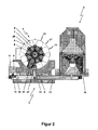
- a workpiece changer 1 is shown for automatic workpiece or pallet change.
- the workpiece changer 1 is constructed in the illustrated embodiment in gantry design and arranged laterally on a machining center 2 to allow lateral loading and unloading of the machining center 2.
- the machining center 2 can be designed in gantry or traveling column construction.
- the workpiece changer 1 has a memory arrangement 3 for workpieces 4 or workpiece pallets 5 with a multiplicity of depositing places 21, which are arranged on a plurality of vertically stacked depositing planes 6, 7 and form the shape of a circular ring.
- the storage spaces 21 are on all storage levels 6, 7 together power-driven about a vertical axis 8 rotatable.
- the workpiece changer 1 furthermore has a handling device 9 for the workpieces 4 or the workpiece pallets 5 located laterally next to the storage arrangement 3.
- the handling device 9 is linearly displaceable along a horizontal axis 10 and linearly along a vertical axis 11 and can additionally be rotated about this vertical axis 11.
- the handling device 9 is moved by means of a drive motor 13 along a bridge 14, which forms the horizontal axis 10.
- the handling device 9 is mounted on a vertical slide 15, which is movable by means of a drive motor 20 in the vertical direction.
- the workpiece changer 1 is mounted on a base frame 12, are arranged on the vertically extending supports 18 which carry the bridge 14. On the base frame 12, a set-up table 17 and a table 19 are further arranged.
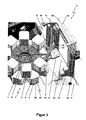
- the storage spaces 21 on a storage level 6, 7 are angularly offset from the storage places 21 on the above and / or underlying storage level 6, 7, so that above and / or below each workpiece 4 or each workpiece pallet 5, a free space is formed in the interference contours 16 of the handling device 9 can immerse in a change process.
- the free space next to each storage space 21 is large enough to supply the workpieces 4 or workpiece pallets 5 with the handling device 9 within the respective storage A, B in the horizontal direction only by a circular or elliptical movement of the respective transfer position 24 or to remove it ,
- the free space next to each storage space 21 is large enough to supply the workpieces 4 or workpiece pallets 5 within the respective storage A, B in the horizontal direction only by the pure circular rotary motion c of the handling device 9 of the respective transfer position 24 or from this to remove.
- One of the storage locations 21 serves as empty space 22 and is not occupied by workpieces 4 or workpiece pallets 5. This makes it possible to transport a workpiece 4 or a workpiece pallet 5 in a linear horizontal direction within the respective storage shelves A, B.
- the empty space 22 is preferably located on the uppermost or the lowest storage level 6, 7.
- each 8 storage spaces 21 are arranged with a uniform circular pitch of 45 °, and the offset between the storage spaces 21 on the vertically adjacent storage levels 6, 7 is 22.5 ° each.
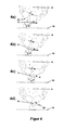
- the automatic loading and unloading of a storage space 21 with the workpiece changer 1 is such that one or more axis movements b, c the handling device 9 and a rotational movement of the memory arrangement 3 are superimposed executed.
- the interference contours 16 of the handling device 9 can dip into the free space between the workpieces 4 or the workpiece pallets 5, which allows a more compact design.
- the automatic loading and unloading of a storage space 21 with the workpiece changer 1 also take place such that the transfer position 24 is approached in a horizontal direction on an elliptical path by the rotational movement c of the handling device 9 performed interpolating with the linear horizontal movement b of the handling device 9 and / or at the same time the rotational movement a of the memory device 3 is performed in order to store larger workpieces 4 or 5 workpiece pallets can.
- the process is complete when the workpiece pallet 5 to be removed has reached the transfer station 24 (see FIG. FIGS. 4a to 4d ).
- the workpiece pallet 5 is received by a gripper device over a short vertical linear movement upwards and removed from the fixation of the storage space 21.
- FIGS. 5a to 5d show a change process within the lower storage level 6 by a pure rotational movement c of the handling device 9. It is also conceivable that the change process is performed by superimposing the movements c and b or c and a or c, b, and a to one less To be able to drive away wide interfering track and thus be able to deposit larger workpieces.
Landscapes
- Engineering & Computer Science (AREA)
- Mechanical Engineering (AREA)
- Feeding Of Workpieces (AREA)
Priority Applications (1)
| Application Number | Priority Date | Filing Date | Title |
|---|---|---|---|
| EP13003718.7A EP2829358B1 (fr) | 2013-07-24 | 2013-07-24 | Changeur de pièce pour le changement automatique de pièces ou de palettes dans un centre d'usinage |
Applications Claiming Priority (1)
| Application Number | Priority Date | Filing Date | Title |
|---|---|---|---|
| EP13003718.7A EP2829358B1 (fr) | 2013-07-24 | 2013-07-24 | Changeur de pièce pour le changement automatique de pièces ou de palettes dans un centre d'usinage |
Publications (2)
| Publication Number | Publication Date |
|---|---|
| EP2829358A1 true EP2829358A1 (fr) | 2015-01-28 |
| EP2829358B1 EP2829358B1 (fr) | 2016-09-21 |
Family
ID=48915792
Family Applications (1)
| Application Number | Title | Priority Date | Filing Date |
|---|---|---|---|
| EP13003718.7A Active EP2829358B1 (fr) | 2013-07-24 | 2013-07-24 | Changeur de pièce pour le changement automatique de pièces ou de palettes dans un centre d'usinage |
Country Status (1)
| Country | Link |
|---|---|
| EP (1) | EP2829358B1 (fr) |
Cited By (3)
| Publication number | Priority date | Publication date | Assignee | Title |
|---|---|---|---|---|
| DE102020115816A1 (de) | 2020-06-16 | 2021-12-16 | Liebherr-Verzahntechnik Gmbh | Speicher- und/oder Fertigungssystem mit wenigstens einem Handhabungsgerät |
| EP4163053A1 (fr) * | 2021-10-06 | 2023-04-12 | WFL Millturn Technologies GmbH & Co. KG | Élément flexible de production |
| CN116457289A (zh) * | 2020-12-08 | 2023-07-18 | 株式会社椿本链条 | 低温保管系统 |
Citations (4)
| Publication number | Priority date | Publication date | Assignee | Title |
|---|---|---|---|---|
| US4986715A (en) * | 1988-07-13 | 1991-01-22 | Tokyo Electron Limited | Stock unit for storing carriers |
| EP0462533A2 (fr) | 1990-06-20 | 1991-12-27 | Matsuura Machinery Corporation | Dispositif de magasin de palettes et dispositif pour échanger des palettes pour machine outil, et tour ayant une palette automatiquement amovible |
| US20040245278A1 (en) * | 2003-01-30 | 2004-12-09 | Steffens Lowell G. | Propane tank vending machine |
| DE102011016713A1 (de) | 2011-04-11 | 2012-10-11 | Liebherr-Verzahntechnik Gmbh | Fertigungssystem |
-
2013
- 2013-07-24 EP EP13003718.7A patent/EP2829358B1/fr active Active
Patent Citations (5)
| Publication number | Priority date | Publication date | Assignee | Title |
|---|---|---|---|---|
| US4986715A (en) * | 1988-07-13 | 1991-01-22 | Tokyo Electron Limited | Stock unit for storing carriers |
| EP0462533A2 (fr) | 1990-06-20 | 1991-12-27 | Matsuura Machinery Corporation | Dispositif de magasin de palettes et dispositif pour échanger des palettes pour machine outil, et tour ayant une palette automatiquement amovible |
| US20040245278A1 (en) * | 2003-01-30 | 2004-12-09 | Steffens Lowell G. | Propane tank vending machine |
| DE102011016713A1 (de) | 2011-04-11 | 2012-10-11 | Liebherr-Verzahntechnik Gmbh | Fertigungssystem |
| EP2511044A2 (fr) * | 2011-04-11 | 2012-10-17 | LIEBHERR-VERZAHNTECHNIK GmbH | Système de fabrication |
Cited By (3)
| Publication number | Priority date | Publication date | Assignee | Title |
|---|---|---|---|---|
| DE102020115816A1 (de) | 2020-06-16 | 2021-12-16 | Liebherr-Verzahntechnik Gmbh | Speicher- und/oder Fertigungssystem mit wenigstens einem Handhabungsgerät |
| CN116457289A (zh) * | 2020-12-08 | 2023-07-18 | 株式会社椿本链条 | 低温保管系统 |
| EP4163053A1 (fr) * | 2021-10-06 | 2023-04-12 | WFL Millturn Technologies GmbH & Co. KG | Élément flexible de production |
Also Published As
| Publication number | Publication date |
|---|---|
| EP2829358B1 (fr) | 2016-09-21 |
Similar Documents
| Publication | Publication Date | Title |
|---|---|---|
| EP2792431B1 (fr) | Installation de traitement pour des composants de structure d'avion | |
| EP2812152B1 (fr) | Machine de rodage à plusieurs postes de travail et table rotative | |
| EP3579987B1 (fr) | Magasin d'outils de cintrage et procédé de chargement d'une presse-plieuse | |
| EP0977651B1 (fr) | Procede et dispositif de fabrication de pieces complexes | |
| DE3823947C2 (fr) | ||
| WO1986003153A1 (fr) | Systeme de fabrication flexible pour le traitement et la production d'ensembles a plusieurs parties, en particulier d'ensembles de carrosseries brutes. | |
| DE102009008647A1 (de) | System zum Wechseln und Einlegen bzw. Vorlegen von Werkzeugen an einer Werkzeugmaschine und Werkzeugmagazin zum Lagern von Werkzeugen | |
| DE102021113892B4 (de) | Kombinierte Transfer- und Speichervorrichtung sowie Anlage zur spanenden Fertigung | |
| EP0908269A2 (fr) | Disposition de machines-outils avec deux unités d'usinage opposées | |
| DE102019204612A1 (de) | Fertigungsstation zur Bearbeitung von Bauteilen | |
| EP4094884A1 (fr) | Système d'usinage et installation d'usinage par enlèvement des copeaux | |
| EP3740344B1 (fr) | Machine-outil pour usinage de pièces par enlèvement de copeaux et procédé de changement de palette sur une machine-outil | |
| EP2829358B1 (fr) | Changeur de pièce pour le changement automatique de pièces ou de palettes dans un centre d'usinage | |
| CH709498B1 (de) | Karussellspeicher für eine Bearbeitungsmaschine sowie Bearbeitungsmaschine mit einem derartigen Karussellspeicher. | |
| EP1511596B1 (fr) | Tour multibroche | |
| CH697416B1 (de) | Handhabungssystem. | |
| DE202009006856U1 (de) | Transportvorrichtung für den Transport von Gegenständen von und zu einer Arbeitsstation | |
| WO2017182015A1 (fr) | Procédé de manipulation de supports de pièces empilés recevant des pièces, à l'intérieur d'une cellule d'automatisation, et cellule d'automatisation pour mettre ledit procédé en oeuvre | |
| EP0129677A2 (fr) | Centre d'usinage pour travaux de fraisage et de perçage | |
| EP2918373A1 (fr) | Dispositif de stockage d'outils pour l'extension de la capacité de stockage d'outils d'un centre d'usinage par forage, fraisage et/ou tournage | |
| DE102019124034B4 (de) | Werkzeugmaschine mit Werzeugwechselmagazin und zugeordnetem Werkzeugspeichermagazin | |
| DE102022119044A1 (de) | Vorrichtung und Verfahren zur Fertigung von Produktvarianten | |
| EP2823933B1 (fr) | Agencement de stockage d'outils pour l'extension de la capacité de stockage d'outils d'un centre d'usinage par forage, fraisage et/ou tournage | |
| DE202007018833U1 (de) | Werkzeugmaschine | |
| DE3816861A1 (de) | Flexible fertigungseinrichtung mit mehreren parallel im abstand nebeneinander angeordneten bearbeitungsmaschinen |
Legal Events
| Date | Code | Title | Description |
|---|---|---|---|
| 17P | Request for examination filed |
Effective date: 20130724 |
|
| AK | Designated contracting states |
Kind code of ref document: A1 Designated state(s): AL AT BE BG CH CY CZ DE DK EE ES FI FR GB GR HR HU IE IS IT LI LT LU LV MC MK MT NL NO PL PT RO RS SE SI SK SM TR |
|
| AX | Request for extension of the european patent |
Extension state: BA ME |
|
| PUAI | Public reference made under article 153(3) epc to a published international application that has entered the european phase |
Free format text: ORIGINAL CODE: 0009012 |
|
| R17P | Request for examination filed (corrected) |
Effective date: 20150216 |
|
| RBV | Designated contracting states (corrected) |
Designated state(s): AL AT BE BG CH CY CZ DE DK EE ES FI FR GB GR HR HU IE IS IT LI LT LU LV MC MK MT NL NO PL PT RO RS SE SI SK SM TR |
|
| GRAP | Despatch of communication of intention to grant a patent |
Free format text: ORIGINAL CODE: EPIDOSNIGR1 |
|
| INTG | Intention to grant announced |
Effective date: 20160617 |
|
| GRAS | Grant fee paid |
Free format text: ORIGINAL CODE: EPIDOSNIGR3 |
|
| GRAA | (expected) grant |
Free format text: ORIGINAL CODE: 0009210 |
|
| AK | Designated contracting states |
Kind code of ref document: B1 Designated state(s): AL AT BE BG CH CY CZ DE DK EE ES FI FR GB GR HR HU IE IS IT LI LT LU LV MC MK MT NL NO PL PT RO RS SE SI SK SM TR |
|
| REG | Reference to a national code |
Ref country code: GB Ref legal event code: FG4D Free format text: NOT ENGLISH |
|
| REG | Reference to a national code |
Ref country code: CH Ref legal event code: EP |
|
| REG | Reference to a national code |
Ref country code: AT Ref legal event code: REF Ref document number: 830648 Country of ref document: AT Kind code of ref document: T Effective date: 20161015 |
|
| REG | Reference to a national code |
Ref country code: IE Ref legal event code: FG4D Free format text: LANGUAGE OF EP DOCUMENT: GERMAN |
|
| REG | Reference to a national code |
Ref country code: DE Ref legal event code: R096 Ref document number: 502013004639 Country of ref document: DE |
|
| REG | Reference to a national code |
Ref country code: CH Ref legal event code: NV Representative=s name: KELLER AND PARTNER PATENTANWAELTE AG, CH |
|
| REG | Reference to a national code |
Ref country code: LT Ref legal event code: MG4D Ref country code: NL Ref legal event code: MP Effective date: 20160921 |
|
| PG25 | Lapsed in a contracting state [announced via postgrant information from national office to epo] |
Ref country code: NO Free format text: LAPSE BECAUSE OF FAILURE TO SUBMIT A TRANSLATION OF THE DESCRIPTION OR TO PAY THE FEE WITHIN THE PRESCRIBED TIME-LIMIT Effective date: 20161221 Ref country code: FI Free format text: LAPSE BECAUSE OF FAILURE TO SUBMIT A TRANSLATION OF THE DESCRIPTION OR TO PAY THE FEE WITHIN THE PRESCRIBED TIME-LIMIT Effective date: 20160921 Ref country code: LT Free format text: LAPSE BECAUSE OF FAILURE TO SUBMIT A TRANSLATION OF THE DESCRIPTION OR TO PAY THE FEE WITHIN THE PRESCRIBED TIME-LIMIT Effective date: 20160921 Ref country code: RS Free format text: LAPSE BECAUSE OF FAILURE TO SUBMIT A TRANSLATION OF THE DESCRIPTION OR TO PAY THE FEE WITHIN THE PRESCRIBED TIME-LIMIT Effective date: 20160921 |
|
| PG25 | Lapsed in a contracting state [announced via postgrant information from national office to epo] |
Ref country code: GR Free format text: LAPSE BECAUSE OF FAILURE TO SUBMIT A TRANSLATION OF THE DESCRIPTION OR TO PAY THE FEE WITHIN THE PRESCRIBED TIME-LIMIT Effective date: 20161222 Ref country code: SE Free format text: LAPSE BECAUSE OF FAILURE TO SUBMIT A TRANSLATION OF THE DESCRIPTION OR TO PAY THE FEE WITHIN THE PRESCRIBED TIME-LIMIT Effective date: 20160921 Ref country code: LV Free format text: LAPSE BECAUSE OF FAILURE TO SUBMIT A TRANSLATION OF THE DESCRIPTION OR TO PAY THE FEE WITHIN THE PRESCRIBED TIME-LIMIT Effective date: 20160921 Ref country code: NL Free format text: LAPSE BECAUSE OF FAILURE TO SUBMIT A TRANSLATION OF THE DESCRIPTION OR TO PAY THE FEE WITHIN THE PRESCRIBED TIME-LIMIT Effective date: 20160921 |
|
| PG25 | Lapsed in a contracting state [announced via postgrant information from national office to epo] |
Ref country code: EE Free format text: LAPSE BECAUSE OF FAILURE TO SUBMIT A TRANSLATION OF THE DESCRIPTION OR TO PAY THE FEE WITHIN THE PRESCRIBED TIME-LIMIT Effective date: 20160921 Ref country code: RO Free format text: LAPSE BECAUSE OF FAILURE TO SUBMIT A TRANSLATION OF THE DESCRIPTION OR TO PAY THE FEE WITHIN THE PRESCRIBED TIME-LIMIT Effective date: 20160921 |
|
| PG25 | Lapsed in a contracting state [announced via postgrant information from national office to epo] |
Ref country code: SK Free format text: LAPSE BECAUSE OF FAILURE TO SUBMIT A TRANSLATION OF THE DESCRIPTION OR TO PAY THE FEE WITHIN THE PRESCRIBED TIME-LIMIT Effective date: 20160921 Ref country code: PT Free format text: LAPSE BECAUSE OF FAILURE TO SUBMIT A TRANSLATION OF THE DESCRIPTION OR TO PAY THE FEE WITHIN THE PRESCRIBED TIME-LIMIT Effective date: 20170123 Ref country code: ES Free format text: LAPSE BECAUSE OF FAILURE TO SUBMIT A TRANSLATION OF THE DESCRIPTION OR TO PAY THE FEE WITHIN THE PRESCRIBED TIME-LIMIT Effective date: 20160921 Ref country code: PL Free format text: LAPSE BECAUSE OF FAILURE TO SUBMIT A TRANSLATION OF THE DESCRIPTION OR TO PAY THE FEE WITHIN THE PRESCRIBED TIME-LIMIT Effective date: 20160921 Ref country code: SM Free format text: LAPSE BECAUSE OF FAILURE TO SUBMIT A TRANSLATION OF THE DESCRIPTION OR TO PAY THE FEE WITHIN THE PRESCRIBED TIME-LIMIT Effective date: 20160921 Ref country code: BG Free format text: LAPSE BECAUSE OF FAILURE TO SUBMIT A TRANSLATION OF THE DESCRIPTION OR TO PAY THE FEE WITHIN THE PRESCRIBED TIME-LIMIT Effective date: 20161221 Ref country code: IS Free format text: LAPSE BECAUSE OF FAILURE TO SUBMIT A TRANSLATION OF THE DESCRIPTION OR TO PAY THE FEE WITHIN THE PRESCRIBED TIME-LIMIT Effective date: 20170121 Ref country code: CZ Free format text: LAPSE BECAUSE OF FAILURE TO SUBMIT A TRANSLATION OF THE DESCRIPTION OR TO PAY THE FEE WITHIN THE PRESCRIBED TIME-LIMIT Effective date: 20160921 |
|
| REG | Reference to a national code |
Ref country code: DE Ref legal event code: R097 Ref document number: 502013004639 Country of ref document: DE |
|
| REG | Reference to a national code |
Ref country code: FR Ref legal event code: PLFP Year of fee payment: 5 |
|
| PLBE | No opposition filed within time limit |
Free format text: ORIGINAL CODE: 0009261 |
|
| STAA | Information on the status of an ep patent application or granted ep patent |
Free format text: STATUS: NO OPPOSITION FILED WITHIN TIME LIMIT |
|
| PG25 | Lapsed in a contracting state [announced via postgrant information from national office to epo] |
Ref country code: DK Free format text: LAPSE BECAUSE OF FAILURE TO SUBMIT A TRANSLATION OF THE DESCRIPTION OR TO PAY THE FEE WITHIN THE PRESCRIBED TIME-LIMIT Effective date: 20160921 |
|
| 26N | No opposition filed |
Effective date: 20170622 |
|
| PG25 | Lapsed in a contracting state [announced via postgrant information from national office to epo] |
Ref country code: SI Free format text: LAPSE BECAUSE OF FAILURE TO SUBMIT A TRANSLATION OF THE DESCRIPTION OR TO PAY THE FEE WITHIN THE PRESCRIBED TIME-LIMIT Effective date: 20160921 |
|
| REG | Reference to a national code |
Ref country code: IE Ref legal event code: MM4A |
|
| PG25 | Lapsed in a contracting state [announced via postgrant information from national office to epo] |
Ref country code: IE Free format text: LAPSE BECAUSE OF NON-PAYMENT OF DUE FEES Effective date: 20170724 |
|
| REG | Reference to a national code |
Ref country code: BE Ref legal event code: MM Effective date: 20170731 |
|
| PG25 | Lapsed in a contracting state [announced via postgrant information from national office to epo] |
Ref country code: LU Free format text: LAPSE BECAUSE OF NON-PAYMENT OF DUE FEES Effective date: 20170724 |
|
| REG | Reference to a national code |
Ref country code: FR Ref legal event code: PLFP Year of fee payment: 6 |
|
| PG25 | Lapsed in a contracting state [announced via postgrant information from national office to epo] |
Ref country code: BE Free format text: LAPSE BECAUSE OF NON-PAYMENT OF DUE FEES Effective date: 20170731 |
|
| PG25 | Lapsed in a contracting state [announced via postgrant information from national office to epo] |
Ref country code: MT Free format text: LAPSE BECAUSE OF FAILURE TO SUBMIT A TRANSLATION OF THE DESCRIPTION OR TO PAY THE FEE WITHIN THE PRESCRIBED TIME-LIMIT Effective date: 20160921 |
|
| PG25 | Lapsed in a contracting state [announced via postgrant information from national office to epo] |
Ref country code: AL Free format text: LAPSE BECAUSE OF FAILURE TO SUBMIT A TRANSLATION OF THE DESCRIPTION OR TO PAY THE FEE WITHIN THE PRESCRIBED TIME-LIMIT Effective date: 20160921 |
|
| PG25 | Lapsed in a contracting state [announced via postgrant information from national office to epo] |
Ref country code: HU Free format text: LAPSE BECAUSE OF FAILURE TO SUBMIT A TRANSLATION OF THE DESCRIPTION OR TO PAY THE FEE WITHIN THE PRESCRIBED TIME-LIMIT; INVALID AB INITIO Effective date: 20130724 Ref country code: MC Free format text: LAPSE BECAUSE OF FAILURE TO SUBMIT A TRANSLATION OF THE DESCRIPTION OR TO PAY THE FEE WITHIN THE PRESCRIBED TIME-LIMIT Effective date: 20160921 |
|
| PG25 | Lapsed in a contracting state [announced via postgrant information from national office to epo] |
Ref country code: CY Free format text: LAPSE BECAUSE OF FAILURE TO SUBMIT A TRANSLATION OF THE DESCRIPTION OR TO PAY THE FEE WITHIN THE PRESCRIBED TIME-LIMIT Effective date: 20160921 |
|
| PG25 | Lapsed in a contracting state [announced via postgrant information from national office to epo] |
Ref country code: MK Free format text: LAPSE BECAUSE OF FAILURE TO SUBMIT A TRANSLATION OF THE DESCRIPTION OR TO PAY THE FEE WITHIN THE PRESCRIBED TIME-LIMIT Effective date: 20160921 |
|
| PG25 | Lapsed in a contracting state [announced via postgrant information from national office to epo] |
Ref country code: TR Free format text: LAPSE BECAUSE OF FAILURE TO SUBMIT A TRANSLATION OF THE DESCRIPTION OR TO PAY THE FEE WITHIN THE PRESCRIBED TIME-LIMIT Effective date: 20160921 |
|
| PG25 | Lapsed in a contracting state [announced via postgrant information from national office to epo] |
Ref country code: HR Free format text: LAPSE BECAUSE OF FAILURE TO SUBMIT A TRANSLATION OF THE DESCRIPTION OR TO PAY THE FEE WITHIN THE PRESCRIBED TIME-LIMIT Effective date: 20160921 |
|
| REG | Reference to a national code |
Ref country code: CH Ref legal event code: PFA Owner name: MASCHINENFABRIK BERTHOLD HERMLE AG, DE Free format text: FORMER OWNER: MASCHINENFABRIK BERTHOLD HERMLE AG, DE |
|
| P01 | Opt-out of the competence of the unified patent court (upc) registered |
Effective date: 20230418 |
|
| PGFP | Annual fee paid to national office [announced via postgrant information from national office to epo] |
Ref country code: DE Payment date: 20250725 Year of fee payment: 13 |
|
| PGFP | Annual fee paid to national office [announced via postgrant information from national office to epo] |
Ref country code: IT Payment date: 20250731 Year of fee payment: 13 |
|
| PGFP | Annual fee paid to national office [announced via postgrant information from national office to epo] |
Ref country code: GB Payment date: 20250724 Year of fee payment: 13 |
|
| PGFP | Annual fee paid to national office [announced via postgrant information from national office to epo] |
Ref country code: FR Payment date: 20250723 Year of fee payment: 13 Ref country code: AT Payment date: 20250721 Year of fee payment: 13 |
|
| PGFP | Annual fee paid to national office [announced via postgrant information from national office to epo] |
Ref country code: CH Payment date: 20250801 Year of fee payment: 13 |