EP2829669A2 - Bassin - Google Patents
Bassin Download PDFInfo
- Publication number
- EP2829669A2 EP2829669A2 EP20140178662 EP14178662A EP2829669A2 EP 2829669 A2 EP2829669 A2 EP 2829669A2 EP 20140178662 EP20140178662 EP 20140178662 EP 14178662 A EP14178662 A EP 14178662A EP 2829669 A2 EP2829669 A2 EP 2829669A2
- Authority
- EP
- European Patent Office
- Prior art keywords
- layer
- swimming pool
- foundation
- edge
- support
- Prior art date
- Legal status (The legal status is an assumption and is not a legal conclusion. Google has not performed a legal analysis and makes no representation as to the accuracy of the status listed.)
- Granted
Links
Images


Classifications
-
- E—FIXED CONSTRUCTIONS
- E04—BUILDING
- E04H—BUILDINGS OR LIKE STRUCTURES FOR PARTICULAR PURPOSES; SWIMMING OR SPLASH BATHS OR POOLS; MASTS; FENCING; TENTS OR CANOPIES, IN GENERAL
- E04H4/00—Swimming or splash baths or pools
- E04H4/0018—Easily movable or transportable swimming pools
- E04H4/0043—Easily movable or transportable swimming pools mainly made of panels
-
- E—FIXED CONSTRUCTIONS
- E04—BUILDING
- E04H—BUILDINGS OR LIKE STRUCTURES FOR PARTICULAR PURPOSES; SWIMMING OR SPLASH BATHS OR POOLS; MASTS; FENCING; TENTS OR CANOPIES, IN GENERAL
- E04H4/00—Swimming or splash baths or pools
- E04H4/0075—Swimming or splash baths or pools made of concrete
- E04H4/0093—Swimming or splash baths or pools made of concrete with walls and floor prefabricated
-
- E—FIXED CONSTRUCTIONS
- E04—BUILDING
- E04H—BUILDINGS OR LIKE STRUCTURES FOR PARTICULAR PURPOSES; SWIMMING OR SPLASH BATHS OR POOLS; MASTS; FENCING; TENTS OR CANOPIES, IN GENERAL
- E04H4/00—Swimming or splash baths or pools
- E04H4/14—Parts, details or accessories not otherwise provided for
- E04H4/141—Coping elements for swimming pools
- E04H4/142—Coping elements for swimming pools with fixing means for sealing foil
-
- E—FIXED CONSTRUCTIONS
- E04—BUILDING
- E04H—BUILDINGS OR LIKE STRUCTURES FOR PARTICULAR PURPOSES; SWIMMING OR SPLASH BATHS OR POOLS; MASTS; FENCING; TENTS OR CANOPIES, IN GENERAL
- E04H4/00—Swimming or splash baths or pools
- E04H4/0018—Easily movable or transportable swimming pools
- E04H2004/0068—Easily movable or transportable swimming pools made of plastic shells or plastic elements including at least parts of walls and floors
Definitions
- the invention relates to a swimming pool, in particular an at least partially absorbable in the ground swimming pool, as well as a support kit for a bathing pool or a swimming pool.
- Pools of the said type are usually provided with a concrete foundation, which supports this against the ground.
- a concrete foundation which supports this against the ground.
- This in turn requires special equipment, such as a concrete mixer to provide of the concrete, which may not be brought close enough to the later place of installation of the swimming pool in confined spaces.
- a concrete mixer to provide of the concrete, which may not be brought close enough to the later place of installation of the swimming pool in confined spaces.
- longer distances must be accepted in order to lay the foundation for such a swimming pool.
- Due to the setting time of the concrete due to a quick work is also required, which usually requires the use of several people.
- the freshly laid foundation has reached a strength only in a few days, which allows the establishment of the pool.
- a swimming pool in particular an at least partially absorbable in the ground swimming pool, with a peripheral edge which comprises a support wall, and this peripheral edge downwards final foundation consisting of a bulk material such as gravel, split and / or sand Equalizing layer for balancing a below the foundation providable soil includes, as well as a extending over it stabilization layer, which consists of individual, connectable, in particular plugged together and / or glued together stabilizing elements.
- the proposal according to the invention combines the rapid and rapid construction of such a swimming pool with the ease of handling of the individual elements necessary for this purpose, which can easily be easily transported by a person and easily mounted by a person. It is an essential advantage of the invention that such pools according to the invention of the usual size are usually created within a working day by a person.
- the object of the invention is not only solved by the above-described swimming pool, but also includes a swimming pool, in particular an at least partially absorbable in the ground swimming pool, with a peripheral edge, which includes a support wall, and this peripheral edge downwards final foundation, the circumferential edge comprises a Randdämm slaughter, which consists of individual, connectable to each other, in particular plugged and / or glued together Randdämm instituten, and the Randdämm harsh is provided on the outside of the support wall and the peripheral edge of a bulk material, in particular of gravel, split and / or sand existing support layer, for balancing and / or supporting a surrounding soil includes, and the support layer is provided on the outside of the support wall.
- a leveling layer is skillfully provided in the foundation according to the invention, which consists of bulk material such as gravel, split and / or sand.
- the same material can be used in the region of the edge as a support layer which greatly facilitates the picking of this material stored as bagged material.
- the compensation layer has the task to achieve a smooth, flat surface in a simple manner by subtracting the poured on the soil Schüttguthaufens and thereby compensate for inaccuracies of the Aushubbodens, further, the compensation layer has the task to evenly load the bath pool in the soil transfer.
- a similar task also has the support layer in the region of the edge. It's about skillfully absorbing the power of the earth surrounding the pool and diverting it around the pool.
- the foundation further comprises a foundation insulation layer, consisting of individual, connectable, in particular can be plugged and / or glued together Foundationdämmimplantationn.
- a foundation insulation layer consisting of individual, connectable, in particular can be plugged and / or glued together Foundationdämmimplantationn.
- the foundation insulation elements may be made of a suitably elastic or soft material, so that any unevenness, for example, of the compensating layer can be cushioned without these directly having an effect on the stabilizing layer. Since the foundation insulation layer can be built up from individual foundation insulation elements, the production of the foundation insulation layer requires only a small amount of personnel and, if required, can also be carried out by only one person.
- the individual foundation insulation elements are also easy to transport, storable and finally connected to each other, so that their overall simple and cost-effective handling is possible.
- the foundation insulation layer extends below the stabilization layer and consists of a softer material than the stabilization layer.
- another layer is thus available in order to achieve a corresponding leveling and alignment of the swimming pool. Because the softer material of the foundation insulation layer absorbs potential unevenness of the leveling layer and also ensures that the stabilization layer is not damaged.
- at one filled pool better load transfer by a particularly good fit of the foundation given to the ground, which leads to a much better stabilization and consequently also durability of the pool.
- the foundation insulation layer is formed as a leveling layer. This can be done, for example, by different thicknesses, elasticities and shapes of the foundation insulation layer or their Grunddämmimplantationn arbitrary adjustments to the respective existing substrate, so that a particularly good balance is possible, on the one hand allows a perfect leveling and alignment of the foundation, and on the other also ensures its very high stability.
- the compensation layer consists of a plurality of cooperating, in particular interconnectable, in particular plugged together and / or glued together compensating elements.
- the leveling layer is produced in a particularly simple and flexible manner and, if necessary, by a single person to lay.
- the individual compensation elements are easy to transport, storable and manageable because they are simple and stable connected to each other.
- the foundation further comprises a nonwoven layer which extends below the foundation insulation layer and / or above the leveling layer.
- a nonwoven layer which extends below the foundation insulation layer and / or above the leveling layer.
- the support wall is designed as a large-area metal ring or sheet metal strip (as a separate, separate component).
- a stable support of the swimming pool against the soil as well as its reliable form retention is effected.
- a correspondingly large-area metal ring or sheet metal strips can form the entire surface of the swimming pool. But this can also consist of several (vertically) stacked individual rings.
- the peripheral edge further comprises a Randdämm slaughter consisting of individual, connectable to each other, in particular plugged and / or glued together Randdämmmaschinen, and the Randdämm Mrs is provided on the outside of the support wall.
- This also lateral thermal insulation of the edge is possible, which significantly reduces the heating costs of the pool.
- the edge insulation layer also forms the support wall.
- Such an edge insulation layer thus no longer makes a separately formed retaining wall absolutely necessary.
- Their supporting effect is provided by the edge insulation layer, which can be 8 cm, 10 cm or 15 cm thick, for example. At the same time, a particularly simple and quick installation of the swimming pool is guaranteed.
- edge insulation formwork element insofar as it serves to force application or force dissipation of the water pressure in the soil and a force transfer task between the support wall and the existing bulk material support layer.
- the edge insulation layer is braced over at least one circumferential tension band. This is on the one hand ensures a connection of the edge insulation elements with each other and thus their better stabilization against the supporting wall, on the other hand results for the peripheral edge of the pool overall a higher stability against surrounding soil.
- the peripheral edge comprises a support layer, in particular a gravel and / or sand layer, for compensating an adjacent soil and the support layer is provided on the outside of the support wall. This is a much better support and thus stabilization of the edge, especially in filled swimming pool possible.
- peripheral edge of the swimming pool is to be understood as consisting of any combination of supporting wall and edge insulation layer and / or supporting layer.
- the space formed by the peripheral edge or the inside of the support wall and the foundation or the top of the stabilizing layer is lined with a waterproof film.
- a waterproof film is a particularly cost-effective and easy-to-install sealing of a swimming pool.
- the foundation is flush with the peripheral edge to exclude settling of the foundation against the edge by loading with the support layer or in the course of later use of the swimming pool. This ensures in particular its tightness, which can not be affected by any potentially occurring displacement between the circumferential edge and foundation.
- At least one rail is provided, to which an upper end of the waterproof film can be fastened.
- the profile rail comprises a clamping element, in which the upper end of the waterproof film can be clamped.
- the profile rail in cross-section h-shaped is executed, and the upper end of the waterproof film has a reinforcement. This results in a stable conclusion of the film with an addition and good clamping effect in the cross section of the rail.
- the film may have an upper attachment piece or a pelmet, which has a wedge-shaped or hook-shaped cross-sectional profile.
- a particularly good fit of the film in the rail is thereby ensured if the H-shaped cross-section has an undercut for holding the reinforcement of the upper end of the waterproof film.
- the storage of the film in the undercut their stable support is ensured, and in particular no subsequent slipping out of the film more possible.
- the at least one profile rail has at least one fastening element projecting therefrom for insertion into a receptacle on the upper edge of the support wall and / or the edge insulation layer. This also makes the rail particularly easy and quick to install, which manifests itself in a reduction in the construction time for the pool.
- the fastening element and the receptacle form a tongue and groove connection, in particular a clip connection. For a particularly stable and long-term durable attachment of the rail is possible.
- a support set in particular a foundation set for a swimming pool or swimming pool, comprising individual stabilizing elements that can be connected to one another, in particular can be plugged together and / or glued together, and a plurality of individual stabilizer layers that can be connected to one another , in particular to each other pluggable and / or glued together Foundationdämmimplantation for supporting the stabilizing layer, wherein the foundation insulation layer of a softer material than the stabilizing layer and in the installed state of the support-sets extends below the stabilizing layer and / or in the installed state of the support-set nor for balancing a surrounding soil and forming a stabilizing layer and the proposed foundation insulation layer, from, preferably provided as bag material compensating material, in particular bulk material such as split, gravel and / or Sand existing leveling layer.
- An essential point of the jacking set consists in the fact that it is very space-saving packable, easily transportable, storable and buildable.
- Such a support set completely replaces a concrete foundation of the same stability and is nevertheless much easier to handle and, above all, considerably less expensive.
- the support set can be acquirable, for example, in construction or construction material stores, and loaded thanks to its space-saving division of the stabilizing layer in individual stabilization elements in a commonly available car and spent at its installation. None else applies to the compensation material, which can also be purchased, loaded and shipped accordingly.
- the support set proposed according to the invention, in particular foundation set comprises (not exhaustive), thus describes a system consisting of the individual elements described above, which offers advantages in their systemic interaction.
- the abovementioned bathing pool can comprise only a supporting wall and a suitable base plate or a peripheral edge area, similar to that of the described swimming pool.
- the gist of this aspect of the invention is that it has been recognized that all components for a functioning foundation can be distributed via the retail trade and that these elements can be used to create a foundation which is completely sufficient for the creation of a pool or swimming pool.
- Essential part The support set or the foundation set is the use of a stabilizing layer, which is formed of relatively hard, but nevertheless transportable and therefore lightweight stabilizing elements.
- the invention deliberately dispenses with the arrangement of a monolithic or integrally rigid support layer, such as a concrete slab, for example, since a foundation which is completely adequate for these purposes is available in a simple and therefore cost-effective variant according to the invention.
- the support set comprises in addition to the stabilizing elements also a plurality of foundation elements which are connectable to a foundation insulation layer and which in turn also consists of light and therefore easily transportable elements. This structure is then also placed on the leveling layer.
- Another advantageous aspect of the invention is to use the prescribed support set, or foundation set also for forming an (additional) foundation on a concrete slab. Therefore, the invention also includes the use of the above-described support set, or foundation set or some or all elements of this set or system for forming a foundation on an already existing on-site concrete slab, for example, on-site by another, older, no longer needed building is already available.
- This aspect is in no way contrary to the avoidance of a concrete slab described above, the aspect is at this point the high flexibility of the subject invention out because an existing concrete slab in the use of the support set, or foundation set does not need to be removed , which offers substantial benefits on the cost side!
- this furthermore comprises individual foundation insulation elements which can be connected to one another to form a foundation insulation layer, in particular can be plugged together and / or glued together, for supporting the stabilization layer.
- individual foundation insulation elements nothing else applies as for the individual stabilizing elements, which can also be packaged to save space, easily transportable and storable, and particularly simple - if required by a single person - can be mounted at the installation of the pool.
- this comprises a nonwoven layer for protecting the foundation insulation layer.
- a nonwoven layer for protecting the foundation insulation layer. This excludes in particular damage or even destruction of the foundation insulation layer due to potential unevenness of the leveling layer, in particular due to sharp stones projecting beyond its surface, whose effect on the foundation insulation layer is damped by the nonwoven layer. This is especially true for a particularly soft or elastic foundation insulation layer, which indeed acts as a balancing and thus stabilizing as well as insulating, but which is also easily damaged.
- the nonwoven layer can of course also be used to protect the stabilization layer, for example, against larger grains and / or stones.
- the stabilizing elements at least partially made of a plastic or PVC material to both a required for transport and storage lightness, as well as a sufficient for stabilization of the swimming pool or outrigger set required rigidity.
- the stabilizing elements also consist of vinyl or other plastic and form a very smooth surface facing the room, since the quality of this surface then also defines the quality of workmanship of the entire swimming pool.
- the individual stabilizing elements can be skilfully connected with each other by appropriate tongue and groove connections with perfect fit, so as to produce a homogeneous, smooth, orderly surface without scratches.
- the edge and / or Grunddämmomme or compensating elements at least partially made of plastic, in particular of foamed or bleached plastic, in particular of expanded or extruded polystyrene.
- the stabilization and / or edge and / or Foundation insulation elements are connected to each other via a tongue and groove joint.
- the support set to an edge insulation layer composable, in particular of individual, connectable to each other, in particular plugged and / or glued together Randdämmimplantation.
- the support set can be packaged to save space, transported and stored, and beyond the edge insulation layer of these edge insulation very easy - if necessary, by only a single person - build.
- the support set comprises bulk material such as gravel or sand, which is provided for forming a supporting layer, for supporting a supporting wall of the bathing pool or the swimming pool.
- the bulk material can also be transported to save space, store and especially obstruct, and easy to buy in construction or construction material stores.
- a support layer is also particularly easy and quick to produce, preferably by a single person.
- the bulk material for the Support layer or leveling layer is provided as bagged. This can be offered in particular in different packaging sizes, so that any size of a future swimming pool can be realized with exactly the required amount of bulk material, without remaining remnants.
- a bagged bulk material is also very easy to transport, storable and portable, and easy to install.
- the support set described above should preferably be used for sealing a swimming pool bottom, since it allows a simple seal without further sealing elements when the individual stabilizing elements of the support set have been made to a total waterproof stabilization layer.
- profile elements are provided for at least partially encompassing and / or mutual coupling of edge regions of individual edge insulation elements.
- edge insulation elements are unstable in the straight areas and tend to fall over. Falling over the edge insulation is thereby reliably prevented by a mutual coupling of the edge regions by the profile elements, whereby a construction of the swimming pool or pool is much easier.
- the abovementioned profile elements and the edge insulation elements are dimensioned and matched to one another such that the profile elements form a edge-free closure on the edge insulation elements.
- On the side of the support layer is thereby avoided in particular that arise in the construction edges that represent a potential risk of injury.
- a particularly reliable and safe construction of the swimming pool is ensured by a edge-free conclusion between profile elements and edge insulation.
- the profile elements have a U-shaped or H-shaped cross-section.
- the profile elements are designed as elongated profile rails. This allows wide sections of the edge insulation elements overlap and thus produce a particularly high coupling stability.
- a corresponding support kit also requires the packaging of significantly fewer items.
- the profile elements are made of a plastic or an aluminum material. Both materials are therefore subject to no corrosion and Compared to comparable materials are rather lightweight, so that both their processing in the construction of a swimming pool as well as their packaging and transport in a support kit are particularly simple.
- the profile elements have prefabricated breaklines for modifying their cross-section.
- This can be advantageous, for example, when corner areas of a swimming pool are to be sheathed with edge insulation elements, which requires embracing or engagement of the profile elements in an angular position of the edge insulation elements which is difficult to achieve by the present cross section of profile elements.
- an H-shaped cross-section of the profile elements could be transformed into an H-shaped cross-section or a T-shaped cross section, as required by engagement or gripping in or around edge regions of edge insulation elements located at an angle to one another a swimming pool provides for their coupling.
- this comprises at least one plate-shaped edge insulation element, so that not only round swimming pools, but also any kind of square swimming pools can be designed.
- the support set described above should preferably be used to build a seen in plan view round or polygonal bath pools or swimming pool, which significantly increases the flexible design of a swimming pool constructed and significantly improved its adaptability to a wide variety of spatial conditions.
- the thickness of the foundation insulating element with the thickness of the stabilizing element forms a quotient in the range from 10 to 100, preferably from 15 to 50, particularly preferably from 20 to 45.
- an interval is specified, which is described by an upper and lower limit.
- the upper limits are, for example, the following values: 35, 40, 45, 50, 55, 60, 65, 70, 80, 90, 100.
- the lower limit is, for example, the following values: 10, 15, 20, 25, 30.
- the disclosure of this application includes the set of all intervals which consists of all possible combinations of the aforementioned upper and lower limits.
- a very thin stabilizing layer realized by a correspondingly thin stabilizing element, in relation to the thickness of the foundation insulation layer (realized by the foundation insulation elements) to surprisingly good, if not very good properties in terms of stability and applicability the stated purpose, namely for a swimming pool or pool.
- very good material pairings are found for the design of the stabilization layer and for the design of the foundation insulation layer.
- the edge insulation element or the foundation insulation element has a thickness of 30 mm to 120 mm, preferably 40 to 100 mm, particularly preferably 45 to 85 mm and a bulk density of 15 to 50 kg / m 3 , preferably 25 up to 45 kg / m 3 .
- an interval is specified, which is described by an upper and lower limit.
- an upper limit for example, the following values are provided: 40 mm, 45 mm, 50 mm, 55 mm, 60 mm, 65 mm, 70 mm, 75 mm, 80 mm, 90 mm, 100 mm, 110 mm, 120 mm.
- the lower limits are, for example, the following values: 10 mm, 20 mm, 25 mm, 30 mm, 35 mm, 40 mm, 45 mm, 50 mm, 55 mm, 60 mm.
- the disclosure of this application encompasses the set of all intervals, which consists of all possible, technically meaningful combinations of the aforementioned upper and lower limits.
- an interval is specified, which is described by an upper and lower limit.
- the upper limit is, for example, the following values: 30 kg / m 3 , 35 kg / m 3 , 40 kg / m 3 , 45 kg / m 3 , 50 kg / m 3 , 55 kg / m 3 , 60 kg / m 3 , 70 kg / m 3 .
- the lower limits are, for example, the following values: 10 kg / m 3 , 15 kg / m 3 , 20 kg / m 3 , 25 kg / m 3 , 30 kg / m 3 .
- the disclosure of this application encompasses the set of all intervals, which consists of all possible, technically meaningful combinations of the aforementioned upper and lower limits.
- the foundation insulation layer can be made of relatively lightweight material (for example, extruded or expanded polystyrene), which reduces costs. In particular, this refers to a bulk density of up to 30 kg / m 3 .
- the foundation insulation layer can be selected relatively thin, this one speaks of thicknesses up to 50 or 55 mm, it still results in sufficient mechanical stability, durability and cost-effective design.
- Fig. 1 shows a cross-sectional side view of a swimming pool or pool 10 according to the invention, which is at least partially embedded in the soil 40.
- This is a pit first excavated, the bottom of which is filled with a leveling layer 31, in particular from bulk material such as split, gravel (in particular small sorting to a maximum of 5, 10, 15 or 20 mm diameter) and / or sand.
- This leveling layer 31 is pulled off and placed in the water, so that a horizontally oriented plane is formed, on which, as shown only by way of example in this embodiment, a nonwoven layer 36 is designed.
- a foundation insulation layer 34 is subsequently applied, which consists of individual, via a tongue and groove joint 50 stackable foundation insulation elements 35.
- the individual Grunddämm comprise 35 should consist in this example of a plastic material such as Styrofoam, on the one hand ensures thermal insulation of the swimming pool 10 down, but at the same time also compensate for any remaining unevenness of the leveling layer 31.
- the nonwoven layer 36 protects the foundation insulation layer 34 from being destroyed by the leveling layer 31 when the swimming pool 10 settles after being filled with water.
- a stabilization layer 32 is laid in a further step, which, similar to the foundation insulation layer 34, consists of individual stabilization elements 33 that can be put together via a tongue and groove joint 50.
- the individual stabilizing elements 33 are to be made here only by way of example from correspondingly shaped vinyl or PVC plates.
- the laying of fleece layer 36, foundation insulation layer 34 and stabilizing layer 32 is thus the foundation 30 of the swimming pool 10 available, on which a peripheral edge 20 are placed can, here a support wall 21, a Randdämm slaughter 22 and a support layer 25 includes.
- the Randdämm slaughter 22 consists of individual Randdämm implantn 23, which are also connected to each other via a corresponding tongue and groove connection 50.
- the edge insulation elements can also be additionally glued together or alternatively only glued together.
- the Randdämm Mrs 22 is raised after issuing the support wall 21 and clamped here only by way of example by a tension band 24 over the circumference of the support wall 21 away against this.
- the edge insulation layer 22 causes on the one hand a thermal insulation of the swimming pool 10 with respect to the soil 40, and on the other hand, a protection of the support wall 21 before the subsequently réellehelitternden support layer 25, so that the swimming pool 10 is also stabilized at its periphery.
- the advantages of the installation method according to the invention for the swimming pool 10 are to be seen in particular in that the foundation 30, consisting of leveling layer 31, nonwoven layer 36, foundation insulation layer 34 and stabilization layer 32, without time restrictions easily by a single person is easily and quickly laid.
- the stabilization layer 32 may well be prepared so that it is used as a waterproof bottom of the swimming pool 10. Complete sealing of the pool 10 would subsequently require only further sealing of the transition between the rim 20 and the foundation 30.
- a corresponding film 60 is used, which lines the space formed by the peripheral edge 20 and the foundation 30 space R, and thus ensures a watertightness of the swimming pool 10.
- peripheral edge 20 can be constructed without time restrictions by a person and finally filled with the leveling layer 31. Both in the production of foundation 30 and edge 20 no delays are expected in comparison to a concrete foundation or concrete trough, which are usually caused by the curing time of the concrete. Accordingly fast swimming pool 10 of the invention can be built up. Appropriate connections for water supply and drainage can be easily installed, since they only require suitable passages in the peripheral edge of the swimming pool 10.
- styrofoam edge insulation layer 22 is easily editable and providable with corresponding recesses that absorb these inflows and outflows and - depending on the thickness of the Randdämm Anlagen 22 - allow their complete recording and disguise therein.
- the complete sinking of the swimming pool 10 in the soil 40 is possible, so that its peripheral edge 20 can be provided with appropriate edge plates, and an aesthetically pleasing pool edge of the swimming pool 10 is formed.
- the foundation 30 is flush with the peripheral edge 20 in order to avoid that when filling the edge 20 with the support layer 25 or during the subsequent use of the swimming pool 10, the foundation 30 sets against the peripheral edge 20.
- the foundation 30 of the swimming pool 10 can be acquired as a supporting set in all that comprises at least the stabilizing elements 33 that can be connected to one another to form a stabilizing layer 32, and a compensating material that can be supported to form a stabilizing layer 32 that supports the stabilizing layer 32.
- a space-saving packable, easily transportable and storable and easy and quick laying foundation opens up the opportunity to set up the peripheral edge 20, to insulate and support if necessary, so that alone the film 60 are attached to seal the pool 10 got to.
- the support kit can already be used individual foundation insulation elements 35 for forming the foundation insulation layer 34 and / or the nonwoven layer 36 to include a same or similar as in Fig. 1 to get shown floor insulation of the swimming pool 10.
- peripheral edge 20 in the form of a package of support wall 21, possibly supplemented by the edge insulation elements 23 and / or the support layer 25 in the package.
- the pool 10 but also be placed at ground level, in the simplest case, for example, by dumping a leveling layer 31 at the point where the pool 10 should be, and according to subsequent attachment of the nonwoven layer 36, 34 and foundation stabilization layer 32. It may, if necessary, also the Randdämm Anlagen 22 of the edge 20 omitted if a corresponding insulation appears superfluous, as well as the nonwoven layer 36 and / or the Grunddämm Anlagen 34 can be omitted if, for example, a particularly fine-grained and extremely compacted leveling layer 31 is providable.
- Fig. 2a shows a cross-sectional side view of an edge region of a swimming pool or swimming pool according to the invention such as the swimming pool 10 of Fig. 1 in which the retaining wall 21 is provided with edge insulation elements 23, the edge region in the upper part of a U-shaped profile element 70, and which are coupled via another H-shaped profile element 70 'together.
- Edge regions of the Randdämmimplantation 23 are each designed so that an edge-free recording of the profile elements 70, 70 'is possible, and so a bending stress is avoided by supporting the support layer 25, which in non-planar conditioning of Randdämmimplantation 23 against the support wall 21 to damage the Edge insulation elements 23 and / or the support wall 21 could lead.
- Fig. 2b shows a cross-sectional plan view of an edge region of a swimming pool or swimming pool according to the invention such as the swimming pool 10 of Fig. 1 , in which the edge insulation elements 23 are coupled together in a corner region via a profile element 70 "" which is H-shaped in cross section. "However, in contrast to the profile elements 70, 70 ', this profile element 70" runs Fig. 2a in the vertical direction and secures the same as in Fig. 2a the plate-shaped edge insulation elements 23 against unintentional falling off during the construction of the swimming pool or pool.
- both the Fig. 2a as well as the Fig. 2b show thus particularly simple ways, by using the profile elements 70,70 'and 70 "both in horizontal and vertical orientation at least in sections, but preferably over an entire length, the stability of the Randdämmimplantation 23 in the construction of the swimming pool or pool 10 significantly
- the vertically and horizontally extending profile elements 70, 70 'and 70 can also be attached in any desired combination. Their transport in a support set as well as their attachment is particularly easy to do and can be done easily by a single person in a short time and at low cost.
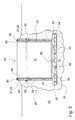
- Fig. 3 shows a cross-sectional side view of another swimming pool or pool 10 'according to the invention, in which, in contrast to the swimming pool or swimming pool 10 of the FIG. 1 the edge insulation layer 22 also forms the support wall 21.
- this swimming pool or bath pool 10 ' is stably constructed, in particular with a suitable choice of the thickness of the edge insulation layer 22, which is preferably 8 cm, 10 cm or even 15 cm can amount.
- a profile rail 80 runs along the upper edge of its edge insulation layer 22, into which the film 60 can be clamped particularly easily and quickly. All other reference numerals of Fig. 3 denote components of the swimming pool or pool 10, as they are already in Fig. 1 are described.
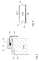
- Fig. 4 shows the cross-sectional side view of the rail 80 of the swimming pool or pool of baths Fig. 3 in an enlarged view, and in particular their h-shaped configuration comprising a clamping element 81 with an undercut 83.
- an end reinforcement 82 of the film 60 is mounted, so that the film 60 is secured against slipping out of the clamping member 81.
- the profiled rail furthermore has a fastening element 84 which projects downwards from the profiled rail 80 in the mounting position and engages in a receptacle 85 of the edge insulation layer 22 forming the support wall 21.
- connection between the fastening element 84 and receptacle 85 can be configured only as a peripheral tongue and groove connection and / or as a selectively attached clip connection.
- the prefabricated profile strip 80 for clamping the film 60 provides their safe and durable support, and can be very quickly and stably attached to the support wall 21 or edge insulation layer 22 itself. This does not apply to the support wall 21 and / or the edge insulation layer 22 of the other Fig. 1 ,
- Fig. 5 schematically shows a preferred embodiment of the foundation 30.
- the significant difference in thickness between the foundation insulation layer 34 and the much thinner stabilization layer 32 is clearly visible.
- the foundation insulation layer 34 formed from a plurality of juxtaposed Grunddämmimplantationn 35 which are connected by tongue and groove connections 50 inserted into one another.
- a nonwoven layer 36 which is to avoid that the bulk material, such as split or sand, enters the vertical gaps between the individual Grunddämmimplantationn 35 and a shock-free pushing together of these elements could prevent.
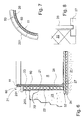
- Fig. 6 goes out from the object Fig. 1 and shows several details.
- the support wall 21 is optionally designed to be very variable and, for example, a metal ring 26, preferably has a steel shell as a pressure-stable ring, the proposed article optionally gives a considerable stability, but without specifying the invention on the presence of this ring.
- the metal ring 26 is delivered as a rolled sheet steel roll, the short sides are flanged and can be connected by a C-profile rail in the unrolled state, so as to give a tensile and compressive forces receiving, stable composite.
- the support wall 21, in particular the metal ring 26 carries at its upper, circumferential end a handrail 11, on which or with which the film 60 is held or fixed.
- a handrail 11 On the handrail 11, for example, a receiving groove for the film 60 is provided or the film 60 is clamped in the gap between the handrail 11 and the upper end of the support wall 21.
- the handrail 11 has a U-shaped recess or groove, which cooperates with the support wall 21 and with the metal ring 26 from the fit forth.
- a decorative plate 200 carries.
- the decorative plate 200 is thereby fastened or glued in the upper region of the edge insulation element 23 with screws.
- the visible surface of the decorative panel 200 carries a decor, for example, a stone pattern or the like, and thus also forms a visible demarcation to the pool.
- the upper side of the support wall 21, in particular the upper side of the edge insulation layer 22, is covered by a cover plate 201.
- the cover plate 201 provides both mechanical protection and optical protection, i. a protection against UV radiation for the preferably made of polystyrene edge insulation element 23rd
- Fig. 7 shows a top view of the edge Fig. 6 in which the hidden elements are indicated by dashed lines.
- the individual Randdämmimplantation 23 are joined together using a tongue and groove joint 50 and are located on the outside of the metal ring 26 and the metal wall 26th
- Fig. 8 shows the detail in the foot so in the lower part of the metal ring 26. It is good to see that the lower (long) edge of the metal ring 26 is in the receiving groove 27 of a foot rail.
- the metal ring 26 is supported on the stabilization layer 32 via a foot rail 27. It can easily be seen that the edge insulation layer 22 has folded out in the foot region, in particular in the region of the foot rail 27.
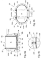
- FIG. 9b a further variant of the swimming pool 10 'according to the invention is shown in plan view.
- the design of the swimming pool 10, 10 'according to the invention is extremely variable, usually such a swimming pool 10 in plan view round but also square or, as in FIG. 9b shown to be oval.
- the round design of the swimming pool 10 leads to a uniform water pressure on the support wall 21, which is supported on the soil 40 via the edge insulation layer 22, the support layer 25.
- the very simple construction of the swimming pool 10 according to the invention is a considerable advantage, since the forces of the water printer is delivered radially evenly over the wall construction to the soil.
- the wall construction is evenly loaded in round swimming pools.
- a straight piece is inserted between the two semicircles and here again the water pressure is to be taken into account, which ultimately strives for a radial equal force distribution and tries to bring the oval swimming pool in a round shape.
- the edge 20 has a boundary support structure 90, which consists of at least one pair of interconnected Abstützholmen 91 a, 91 a ', 91 b, 91 b', the Edge 20 of the swimming pool 10, 10 ', opposite each other, are arranged.
- the arrangement is chosen so that from the inside to the outside of the space R of the (one-piece or tightly welded from several parts) film 60 is limited.
- the film 60 then rests on the support wall 21, the farther outward from the edge insulation layer 22 with respect to, in FIG. 9b Not shown soil 40 is supported on the support layer 25.
- the edge support structure 90 is provided in the straight, central region 15, the edge support structure 90 is provided.
- the edge support structure 90 is just at the transition region of the straight, central region 15 in the round area.
- At least one edge damping element 23a, 23b is provided in the round regions.
- substantially straight edge insulation elements 23c and 23d are arranged in the straight regions 15 in the straight regions 15 in the straight regions 15 in the straight regions 15 in the straight regions 15 in the straight regions 15 substantially straight edge insulation elements 23c and 23d are arranged.
- the support beams 91a, 91a ', 91b, 91b' are designed as double T-beams and allow the edge insulation elements 23a, 23b, 23c and 23d to rest in them. This is for example in the enlarged detail FIG. 9c shown.
- the arrangement is chosen such that the support wall 21 rests against the inside of the respective support spars 91a, 91a ', 91b, 91b' facing the space R and thus transfers the water pressure to the support spars 91a, 91a ', 91b, 91b' ,
- Two pairs of support bars 91a, 91a 'and 91b, 91b' are each interconnected by a connecting strut 92a, 92b and result in a self-supporting construction.
- FIG. 9a the cut is shown.
- the connecting strut 92b rests on the foundation 30, in particular the stabilizing layer 32, formed from the individual stabilizing elements 33.
- the height of the Abstützholmens 91a, 91a 'and 91b, 91b' corresponds to the height of the swimming pool 10, but without defining the invention thereto. Since usually a swimming pool is not completely filled, it may be sufficient, the height of Abstweilholmens 91a, 91a 'and 91b, 91b' lower, the usual water level to choose accordingly because ultimately only in this area, a corresponding load bearing is necessary. In this respect, the height of AbstNeillholmens 91a, 91a 'and 91b, 91b 'between 50 and 80%, preferably approximately between 60 and 65% of the depth of the pool calculated from the upper edge to the bottom plate) amount.
- the foundation (30) furthermore comprises a foundation insulation layer (34) which consists of individual foundation insulation elements (35) which can be connected to each other, in particular can be plugged together and / or bonded together, the foundation insulation layer (34) extends below the stabilization layer (32) and consists of a softer material than the stabilization layer (32), the foundation insulation layer (34) is designed as a compensation layer (31), the compensation layer (31) consists of a plurality of cooperating, in particular interconnectable, in particular pluggable and / or glued together compensation elements, is provided as a leveling layer (31), the foundation (30) further comprises a nonwoven layer (36) extending below the foundation insulation layer (34) and / or above the leveling layer (31), between the foundation insulation layer (34) and the leveling layer (31) no further rigid or monolithic base layer, for.
- a foundation insulation layer (34) which consists of individual foundation insulation elements (35) which can be connected to each other, in particular can be plugged together and / or bonded together, the foundation insulation layer (34) extends below
- the support wall (21) is at least partially designed as a large-area metal ring or sheet metal strip (26)
- the edge insulation layer (22) also forms the support wall (21)
- the edge insulation layer (22) is clamped over at least one circulating tension band (24)
- the space (R) formed by the circumferential edge (20) or the inside of the support wall (21) and the foundation (30) or the top of the stabilization layer (32) is lined with a watertight film (60)
- the foundation (30) is flush with the peripheral edge (20)
- at least one profile rail (80) is provided, to which an upper end of the waterproof film (60) can be fastened
- the profiled rail (80) comprises a clamping element (81) into which the upper end of the watertight film (60) can be clamped
- the profiled rail (80) is H-shaped in cross-section
- the upper end of the watertight film (60) has a reinforcement (82)
- the H-shaped cross section of the profile rail (80) has an undercut (8
- the profile elements (70 ... 70 ') and the edge insulation elements (23) are dimensioned and matched to one another such that the profile elements (70 ... 70') form a edge-free closure on the edge insulation elements (23), the profile elements (70 ... 70 ') have a U-shaped or H-shaped cross-section, the profile elements (70 ... 70 ') are designed as elongate profile rails, the profile elements (70 ... 70 ') are made of a plastic or an aluminum material, the profile elements (70 ...
- the support wall (21), in particular the metal ring (26) carries at its upper, circumferential end a handrail (11) on which or with which the film (60) is held or fastened, the outer side of the support wall (21), in particular the outer side of the edge insulation layer (22), bears a decorative panel (200), in particular on the area projecting out of the ground, the upper side of the support wall (21), in particular the upper side of the edge insulation layer (22), is covered by a cover plate (201), the handrail (11) is arranged above the cover plate (201), the metal ring (26) is supported on the stabilization layer (32) via a foot rail (27), the edge insulation layer (22) in the foot region, in particular in the region of the foot rail (27), is folded out,
Landscapes
- Engineering & Computer Science (AREA)
- Architecture (AREA)
- Civil Engineering (AREA)
- Structural Engineering (AREA)
- Building Environments (AREA)
- Investigation Of Foundation Soil And Reinforcement Of Foundation Soil By Compacting Or Drainage (AREA)
- Floor Finish (AREA)
Applications Claiming Priority (4)
| Application Number | Priority Date | Filing Date | Title |
|---|---|---|---|
| DE202013103392 | 2013-07-26 | ||
| DE202013009161 | 2013-10-17 | ||
| DE202014100367 | 2014-01-28 | ||
| DE202014100625 | 2014-02-12 |
Publications (3)
| Publication Number | Publication Date |
|---|---|
| EP2829669A2 true EP2829669A2 (fr) | 2015-01-28 |
| EP2829669A3 EP2829669A3 (fr) | 2015-06-24 |
| EP2829669B1 EP2829669B1 (fr) | 2020-10-21 |
Family
ID=51224834
Family Applications (1)
| Application Number | Title | Priority Date | Filing Date |
|---|---|---|---|
| EP14178662.4A Active EP2829669B1 (fr) | 2013-07-26 | 2014-07-25 | Piscine |
Country Status (2)
| Country | Link |
|---|---|
| EP (1) | EP2829669B1 (fr) |
| DE (1) | DE202014103453U1 (fr) |
Cited By (4)
| Publication number | Priority date | Publication date | Assignee | Title |
|---|---|---|---|---|
| CZ307152B6 (cs) * | 2016-08-22 | 2018-02-07 | Winchester Se | Postup výroby bazénu z polypropylenu a přípravek k provádění tohoto postupu |
| AT519182A1 (de) * | 2016-09-28 | 2018-04-15 | Christopher Doppelreiter | Mehrteilige, modular aufbaubare Vorrichtung zum äußeren Schutz eines Schwimmbeckens |
| WO2024119478A1 (fr) * | 2022-12-09 | 2024-06-13 | 王加清 | Sangle de traction de corps de hauban en forme d'onde carrée et son procédé de fabrication |
| AT526948A4 (de) * | 2023-08-14 | 2024-09-15 | Trischler Dr Heinrich | Tank |
Families Citing this family (2)
| Publication number | Priority date | Publication date | Assignee | Title |
|---|---|---|---|---|
| DE102019118223B4 (de) | 2019-07-05 | 2026-03-12 | Envola GmbH | Vorrichtung zur Energieübertragung und zur Energiespeicherung in einem Flüssigkeitsreservoir |
| FR3149336B1 (fr) * | 2023-05-31 | 2025-06-20 | Swimnspa | Structure multi-couches pour bassin de baignade formant spa, spa de nage ou piscine |
Family Cites Families (4)
| Publication number | Priority date | Publication date | Assignee | Title |
|---|---|---|---|---|
| DE1955078A1 (de) * | 1969-11-03 | 1971-05-27 | Karl Alt Behaelterbau Appbau | Schwimmbecken |
| US3971075A (en) * | 1974-05-08 | 1976-07-27 | Heinbaugh Kenneth D | Swimming pool structure |
| FR2856332B1 (fr) * | 2003-06-20 | 2007-03-23 | Piscines Desjoyaux Sa | Panneau pour la realisation d'un bassin de piscine |
| FR2917441B1 (fr) * | 2007-06-15 | 2009-10-09 | Frederic Baron | Procede de pose d'un accessoire au travers d'un panneau pour la construction d'une piscine |
-
2014
- 2014-07-25 EP EP14178662.4A patent/EP2829669B1/fr active Active
- 2014-07-25 DE DE201420103453 patent/DE202014103453U1/de not_active Expired - Lifetime
Non-Patent Citations (1)
| Title |
|---|
| None |
Cited By (7)
| Publication number | Priority date | Publication date | Assignee | Title |
|---|---|---|---|---|
| CZ307152B6 (cs) * | 2016-08-22 | 2018-02-07 | Winchester Se | Postup výroby bazénu z polypropylenu a přípravek k provádění tohoto postupu |
| AT519182A1 (de) * | 2016-09-28 | 2018-04-15 | Christopher Doppelreiter | Mehrteilige, modular aufbaubare Vorrichtung zum äußeren Schutz eines Schwimmbeckens |
| AT519182B1 (de) * | 2016-09-28 | 2018-07-15 | Christopher Doppelreiter | Mehrteilige, modular aufbaubare Vorrichtung zum äußeren Schutz eines Schwimmbeckens |
| WO2024119478A1 (fr) * | 2022-12-09 | 2024-06-13 | 王加清 | Sangle de traction de corps de hauban en forme d'onde carrée et son procédé de fabrication |
| AT526948A4 (de) * | 2023-08-14 | 2024-09-15 | Trischler Dr Heinrich | Tank |
| AT526948B1 (de) * | 2023-08-14 | 2024-09-15 | Trischler Dr Heinrich | Tank |
| WO2025036932A1 (fr) * | 2023-08-14 | 2025-02-20 | Heinrich Trischler | Réservoir |
Also Published As
| Publication number | Publication date |
|---|---|
| EP2829669B1 (fr) | 2020-10-21 |
| EP2829669A3 (fr) | 2015-06-24 |
| DE202014103453U1 (de) | 2014-10-22 |
Similar Documents
| Publication | Publication Date | Title |
|---|---|---|
| EP2829669B1 (fr) | Piscine | |
| EP0235843A1 (fr) | Pièce de fixation pour réaliser des murs par moulage dans des coffrages permanents | |
| DE2226889A1 (de) | Bausystem, insbesondere zur Ernch tung von Gebäuden, Container und Fahr zeugaufbauten | |
| DE102014006489A1 (de) | Variables Stecksystem formschlüssiger Bauteile | |
| DE1559288C3 (de) | Im Erdboden Hegendes Schwimmbecken | |
| DE7717322U1 (de) | Sturz zur abstuetzung der aeusseren mauerschicht von mauerwerk ueber wandoeffnungen | |
| DE202008012263U1 (de) | Wandverkleidung mit Füllmaterial | |
| DE2519232A1 (de) | Bauelementsystem zur erstellung bepflanzbarer mauern | |
| DE2117711A1 (de) | Auf den Erdboden aufsetzbarer Fundamentständer | |
| EP2535463B1 (fr) | Mur de soutènement préfabriqué modulaire, mur de soutènement en béton ainsi fabriqué et procédé de montage du mur de soutènement | |
| EP1927706B1 (fr) | Revêtement mural pour une façade | |
| AT391731B (de) | Deckenplatte und verfahren zu ihrer herstellung sowie anordnung zur durchfuehrung des verfahrens | |
| DE102005033545B4 (de) | Ausrüstungsträger mit zurgeordneter Beschwerungsmasse, der zur Befestigung bautechnischer Ausrüstungen dient | |
| DE2020607B2 (de) | Mehrstöckiges Gebäude aus einheitlichen, vorgefertigten Raumzellen | |
| DE102007036965B4 (de) | Bauwerk zur Aufbewahrung von Urnen | |
| DE7027429U (de) | Vorgefertigtes raumelement zur errichtung von gebaeuden. | |
| AT18100U1 (de) | Wasserbecken mit integriertem und/oder externem Ablauf | |
| DE29509938U1 (de) | Schalstütze | |
| CH711288B1 (de) | Wasserdurchlässige Stützkonstruktion, insbesondere zur Böschungsstabilisierung sowie zur Terrassierung und Terraingestaltung. | |
| CH638853A5 (en) | Structural element for fabricating structures and use of the same for fabricating walls | |
| DE102019119417A1 (de) | Schalungselement | |
| DE102010034600B4 (de) | Randbegrenzungsbord | |
| DE102011000231A1 (de) | Schallschutzelement und Verfahren zum Fertigen eines Schallschutzelementes | |
| DE10205205A1 (de) | Wandbauelement | |
| DE2322920A1 (de) | Fertigbauteil fuer die herstellung von gebaeuden |
Legal Events
| Date | Code | Title | Description |
|---|---|---|---|
| 17P | Request for examination filed |
Effective date: 20140725 |
|
| AK | Designated contracting states |
Kind code of ref document: A2 Designated state(s): AL AT BE BG CH CY CZ DE DK EE ES FI FR GB GR HR HU IE IS IT LI LT LU LV MC MK MT NL NO PL PT RO RS SE SI SK SM TR |
|
| AX | Request for extension of the european patent |
Extension state: BA ME |
|
| PUAI | Public reference made under article 153(3) epc to a published international application that has entered the european phase |
Free format text: ORIGINAL CODE: 0009012 |
|
| PUAL | Search report despatched |
Free format text: ORIGINAL CODE: 0009013 |
|
| AK | Designated contracting states |
Kind code of ref document: A3 Designated state(s): AL AT BE BG CH CY CZ DE DK EE ES FI FR GB GR HR HU IE IS IT LI LT LU LV MC MK MT NL NO PL PT RO RS SE SI SK SM TR |
|
| AX | Request for extension of the european patent |
Extension state: BA ME |
|
| RIC1 | Information provided on ipc code assigned before grant |
Ipc: E04H 4/00 20060101AFI20150518BHEP |
|
| R17P | Request for examination filed (corrected) |
Effective date: 20151223 |
|
| RBV | Designated contracting states (corrected) |
Designated state(s): AL AT BE BG CH CY CZ DE DK EE ES FI FR GB GR HR HU IE IS IT LI LT LU LV MC MK MT NL NO PL PT RO RS SE SI SK SM TR |
|
| STAA | Information on the status of an ep patent application or granted ep patent |
Free format text: STATUS: EXAMINATION IS IN PROGRESS |
|
| 17Q | First examination report despatched |
Effective date: 20170420 |
|
| GRAP | Despatch of communication of intention to grant a patent |
Free format text: ORIGINAL CODE: EPIDOSNIGR1 |
|
| STAA | Information on the status of an ep patent application or granted ep patent |
Free format text: STATUS: GRANT OF PATENT IS INTENDED |
|
| INTG | Intention to grant announced |
Effective date: 20200706 |
|
| GRAS | Grant fee paid |
Free format text: ORIGINAL CODE: EPIDOSNIGR3 |
|
| GRAA | (expected) grant |
Free format text: ORIGINAL CODE: 0009210 |
|
| STAA | Information on the status of an ep patent application or granted ep patent |
Free format text: STATUS: THE PATENT HAS BEEN GRANTED |
|
| AK | Designated contracting states |
Kind code of ref document: B1 Designated state(s): AL AT BE BG CH CY CZ DE DK EE ES FI FR GB GR HR HU IE IS IT LI LT LU LV MC MK MT NL NO PL PT RO RS SE SI SK SM TR |
|
| REG | Reference to a national code |
Ref country code: GB Ref legal event code: FG4D Free format text: NOT ENGLISH |
|
| REG | Reference to a national code |
Ref country code: CH Ref legal event code: EP |
|
| REG | Reference to a national code |
Ref country code: IE Ref legal event code: FG4D Free format text: LANGUAGE OF EP DOCUMENT: GERMAN |
|
| REG | Reference to a national code |
Ref country code: DE Ref legal event code: R096 Ref document number: 502014014909 Country of ref document: DE |
|
| REG | Reference to a national code |
Ref country code: AT Ref legal event code: REF Ref document number: 1326006 Country of ref document: AT Kind code of ref document: T Effective date: 20201115 |
|
| REG | Reference to a national code |
Ref country code: CH Ref legal event code: NV Representative=s name: ISLER AND PEDRAZZINI AG, CH |
|
| REG | Reference to a national code |
Ref country code: NL Ref legal event code: MP Effective date: 20201021 |
|
| PG25 | Lapsed in a contracting state [announced via postgrant information from national office to epo] |
Ref country code: GR Free format text: LAPSE BECAUSE OF FAILURE TO SUBMIT A TRANSLATION OF THE DESCRIPTION OR TO PAY THE FEE WITHIN THE PRESCRIBED TIME-LIMIT Effective date: 20210122 Ref country code: RS Free format text: LAPSE BECAUSE OF FAILURE TO SUBMIT A TRANSLATION OF THE DESCRIPTION OR TO PAY THE FEE WITHIN THE PRESCRIBED TIME-LIMIT Effective date: 20201021 Ref country code: FI Free format text: LAPSE BECAUSE OF FAILURE TO SUBMIT A TRANSLATION OF THE DESCRIPTION OR TO PAY THE FEE WITHIN THE PRESCRIBED TIME-LIMIT Effective date: 20201021 Ref country code: PT Free format text: LAPSE BECAUSE OF FAILURE TO SUBMIT A TRANSLATION OF THE DESCRIPTION OR TO PAY THE FEE WITHIN THE PRESCRIBED TIME-LIMIT Effective date: 20210222 Ref country code: NO Free format text: LAPSE BECAUSE OF FAILURE TO SUBMIT A TRANSLATION OF THE DESCRIPTION OR TO PAY THE FEE WITHIN THE PRESCRIBED TIME-LIMIT Effective date: 20210121 Ref country code: NL Free format text: LAPSE BECAUSE OF FAILURE TO SUBMIT A TRANSLATION OF THE DESCRIPTION OR TO PAY THE FEE WITHIN THE PRESCRIBED TIME-LIMIT Effective date: 20201021 |
|
| REG | Reference to a national code |
Ref country code: LT Ref legal event code: MG4D |
|
| PG25 | Lapsed in a contracting state [announced via postgrant information from national office to epo] |
Ref country code: IS Free format text: LAPSE BECAUSE OF FAILURE TO SUBMIT A TRANSLATION OF THE DESCRIPTION OR TO PAY THE FEE WITHIN THE PRESCRIBED TIME-LIMIT Effective date: 20210221 Ref country code: LV Free format text: LAPSE BECAUSE OF FAILURE TO SUBMIT A TRANSLATION OF THE DESCRIPTION OR TO PAY THE FEE WITHIN THE PRESCRIBED TIME-LIMIT Effective date: 20201021 Ref country code: SE Free format text: LAPSE BECAUSE OF FAILURE TO SUBMIT A TRANSLATION OF THE DESCRIPTION OR TO PAY THE FEE WITHIN THE PRESCRIBED TIME-LIMIT Effective date: 20201021 Ref country code: PL Free format text: LAPSE BECAUSE OF FAILURE TO SUBMIT A TRANSLATION OF THE DESCRIPTION OR TO PAY THE FEE WITHIN THE PRESCRIBED TIME-LIMIT Effective date: 20201021 Ref country code: ES Free format text: LAPSE BECAUSE OF FAILURE TO SUBMIT A TRANSLATION OF THE DESCRIPTION OR TO PAY THE FEE WITHIN THE PRESCRIBED TIME-LIMIT Effective date: 20201021 Ref country code: BG Free format text: LAPSE BECAUSE OF FAILURE TO SUBMIT A TRANSLATION OF THE DESCRIPTION OR TO PAY THE FEE WITHIN THE PRESCRIBED TIME-LIMIT Effective date: 20210121 |
|
| PG25 | Lapsed in a contracting state [announced via postgrant information from national office to epo] |
Ref country code: HR Free format text: LAPSE BECAUSE OF FAILURE TO SUBMIT A TRANSLATION OF THE DESCRIPTION OR TO PAY THE FEE WITHIN THE PRESCRIBED TIME-LIMIT Effective date: 20201021 |
|
| REG | Reference to a national code |
Ref country code: DE Ref legal event code: R097 Ref document number: 502014014909 Country of ref document: DE |
|
| PG25 | Lapsed in a contracting state [announced via postgrant information from national office to epo] |
Ref country code: LT Free format text: LAPSE BECAUSE OF FAILURE TO SUBMIT A TRANSLATION OF THE DESCRIPTION OR TO PAY THE FEE WITHIN THE PRESCRIBED TIME-LIMIT Effective date: 20201021 Ref country code: SK Free format text: LAPSE BECAUSE OF FAILURE TO SUBMIT A TRANSLATION OF THE DESCRIPTION OR TO PAY THE FEE WITHIN THE PRESCRIBED TIME-LIMIT Effective date: 20201021 Ref country code: RO Free format text: LAPSE BECAUSE OF FAILURE TO SUBMIT A TRANSLATION OF THE DESCRIPTION OR TO PAY THE FEE WITHIN THE PRESCRIBED TIME-LIMIT Effective date: 20201021 Ref country code: EE Free format text: LAPSE BECAUSE OF FAILURE TO SUBMIT A TRANSLATION OF THE DESCRIPTION OR TO PAY THE FEE WITHIN THE PRESCRIBED TIME-LIMIT Effective date: 20201021 Ref country code: CZ Free format text: LAPSE BECAUSE OF FAILURE TO SUBMIT A TRANSLATION OF THE DESCRIPTION OR TO PAY THE FEE WITHIN THE PRESCRIBED TIME-LIMIT Effective date: 20201021 Ref country code: SM Free format text: LAPSE BECAUSE OF FAILURE TO SUBMIT A TRANSLATION OF THE DESCRIPTION OR TO PAY THE FEE WITHIN THE PRESCRIBED TIME-LIMIT Effective date: 20201021 |
|
| PLBE | No opposition filed within time limit |
Free format text: ORIGINAL CODE: 0009261 |
|
| STAA | Information on the status of an ep patent application or granted ep patent |
Free format text: STATUS: NO OPPOSITION FILED WITHIN TIME LIMIT |
|
| PG25 | Lapsed in a contracting state [announced via postgrant information from national office to epo] |
Ref country code: DK Free format text: LAPSE BECAUSE OF FAILURE TO SUBMIT A TRANSLATION OF THE DESCRIPTION OR TO PAY THE FEE WITHIN THE PRESCRIBED TIME-LIMIT Effective date: 20201021 |
|
| 26N | No opposition filed |
Effective date: 20210722 |
|
| PG25 | Lapsed in a contracting state [announced via postgrant information from national office to epo] |
Ref country code: IT Free format text: LAPSE BECAUSE OF FAILURE TO SUBMIT A TRANSLATION OF THE DESCRIPTION OR TO PAY THE FEE WITHIN THE PRESCRIBED TIME-LIMIT Effective date: 20201021 Ref country code: AL Free format text: LAPSE BECAUSE OF FAILURE TO SUBMIT A TRANSLATION OF THE DESCRIPTION OR TO PAY THE FEE WITHIN THE PRESCRIBED TIME-LIMIT Effective date: 20201021 |
|
| PG25 | Lapsed in a contracting state [announced via postgrant information from national office to epo] |
Ref country code: SI Free format text: LAPSE BECAUSE OF FAILURE TO SUBMIT A TRANSLATION OF THE DESCRIPTION OR TO PAY THE FEE WITHIN THE PRESCRIBED TIME-LIMIT Effective date: 20201021 |
|
| GBPC | Gb: european patent ceased through non-payment of renewal fee |
Effective date: 20210725 |
|
| PG25 | Lapsed in a contracting state [announced via postgrant information from national office to epo] |
Ref country code: MC Free format text: LAPSE BECAUSE OF FAILURE TO SUBMIT A TRANSLATION OF THE DESCRIPTION OR TO PAY THE FEE WITHIN THE PRESCRIBED TIME-LIMIT Effective date: 20201021 |
|
| REG | Reference to a national code |
Ref country code: BE Ref legal event code: MM Effective date: 20210731 |
|
| PG25 | Lapsed in a contracting state [announced via postgrant information from national office to epo] |
Ref country code: GB Free format text: LAPSE BECAUSE OF NON-PAYMENT OF DUE FEES Effective date: 20210725 |
|
| PG25 | Lapsed in a contracting state [announced via postgrant information from national office to epo] |
Ref country code: IS Free format text: LAPSE BECAUSE OF FAILURE TO SUBMIT A TRANSLATION OF THE DESCRIPTION OR TO PAY THE FEE WITHIN THE PRESCRIBED TIME-LIMIT Effective date: 20210221 Ref country code: LU Free format text: LAPSE BECAUSE OF NON-PAYMENT OF DUE FEES Effective date: 20210725 |
|
| PG25 | Lapsed in a contracting state [announced via postgrant information from national office to epo] |
Ref country code: IE Free format text: LAPSE BECAUSE OF NON-PAYMENT OF DUE FEES Effective date: 20210725 Ref country code: BE Free format text: LAPSE BECAUSE OF NON-PAYMENT OF DUE FEES Effective date: 20210731 |
|
| REG | Reference to a national code |
Ref country code: DE Ref legal event code: R082 Ref document number: 502014014909 Country of ref document: DE Representative=s name: PATENTANWAELTE OLBRICHT, BUCHHOLD, KEULERTZ PA, DE |
|
| PG25 | Lapsed in a contracting state [announced via postgrant information from national office to epo] |
Ref country code: HU Free format text: LAPSE BECAUSE OF FAILURE TO SUBMIT A TRANSLATION OF THE DESCRIPTION OR TO PAY THE FEE WITHIN THE PRESCRIBED TIME-LIMIT; INVALID AB INITIO Effective date: 20140725 |
|
| PG25 | Lapsed in a contracting state [announced via postgrant information from national office to epo] |
Ref country code: CY Free format text: LAPSE BECAUSE OF FAILURE TO SUBMIT A TRANSLATION OF THE DESCRIPTION OR TO PAY THE FEE WITHIN THE PRESCRIBED TIME-LIMIT Effective date: 20201021 |
|
| PG25 | Lapsed in a contracting state [announced via postgrant information from national office to epo] |
Ref country code: MK Free format text: LAPSE BECAUSE OF FAILURE TO SUBMIT A TRANSLATION OF THE DESCRIPTION OR TO PAY THE FEE WITHIN THE PRESCRIBED TIME-LIMIT Effective date: 20201021 |
|
| PG25 | Lapsed in a contracting state [announced via postgrant information from national office to epo] |
Ref country code: MT Free format text: LAPSE BECAUSE OF FAILURE TO SUBMIT A TRANSLATION OF THE DESCRIPTION OR TO PAY THE FEE WITHIN THE PRESCRIBED TIME-LIMIT Effective date: 20201021 |
|
| PGFP | Annual fee paid to national office [announced via postgrant information from national office to epo] |
Ref country code: DE Payment date: 20250731 Year of fee payment: 12 |
|
| PGFP | Annual fee paid to national office [announced via postgrant information from national office to epo] |
Ref country code: FR Payment date: 20250725 Year of fee payment: 12 Ref country code: AT Payment date: 20250722 Year of fee payment: 12 |
|
| PGFP | Annual fee paid to national office [announced via postgrant information from national office to epo] |
Ref country code: CH Payment date: 20250801 Year of fee payment: 12 |
|
| PG25 | Lapsed in a contracting state [announced via postgrant information from national office to epo] |
Ref country code: TR Free format text: LAPSE BECAUSE OF FAILURE TO SUBMIT A TRANSLATION OF THE DESCRIPTION OR TO PAY THE FEE WITHIN THE PRESCRIBED TIME-LIMIT Effective date: 20201021 |