EP2829892A1 - Procédé de traitement assisté par ordinateur de données RSO - Google Patents
Procédé de traitement assisté par ordinateur de données RSO Download PDFInfo
- Publication number
- EP2829892A1 EP2829892A1 EP14175418.4A EP14175418A EP2829892A1 EP 2829892 A1 EP2829892 A1 EP 2829892A1 EP 14175418 A EP14175418 A EP 14175418A EP 2829892 A1 EP2829892 A1 EP 2829892A1
- Authority
- EP
- European Patent Office
- Prior art keywords
- data acquisition
- azimuth
- positions
- sar
- missing
- Prior art date
- Legal status (The legal status is an assumption and is not a legal conclusion. Google has not performed a legal analysis and makes no representation as to the accuracy of the status listed.)
- Granted
Links
Images


Classifications
-
- G—PHYSICS
- G01—MEASURING; TESTING
- G01S—RADIO DIRECTION-FINDING; RADIO NAVIGATION; DETERMINING DISTANCE OR VELOCITY BY USE OF RADIO WAVES; LOCATING OR PRESENCE-DETECTING BY USE OF THE REFLECTION OR RERADIATION OF RADIO WAVES; ANALOGOUS ARRANGEMENTS USING OTHER WAVES
- G01S7/00—Details of systems according to groups G01S13/00, G01S15/00, G01S17/00
- G01S7/02—Details of systems according to groups G01S13/00, G01S15/00, G01S17/00 of systems according to group G01S13/00
- G01S7/28—Details of pulse systems
- G01S7/285—Receivers
- G01S7/295—Means for transforming co-ordinates or for evaluating data, e.g. using computers
-
- G—PHYSICS
- G01—MEASURING; TESTING
- G01S—RADIO DIRECTION-FINDING; RADIO NAVIGATION; DETERMINING DISTANCE OR VELOCITY BY USE OF RADIO WAVES; LOCATING OR PRESENCE-DETECTING BY USE OF THE REFLECTION OR RERADIATION OF RADIO WAVES; ANALOGOUS ARRANGEMENTS USING OTHER WAVES
- G01S13/00—Systems using the reflection or reradiation of radio waves, e.g. radar systems; Analogous systems using reflection or reradiation of waves whose nature or wavelength is irrelevant or unspecified
- G01S13/88—Radar or analogous systems specially adapted for specific applications
- G01S13/89—Radar or analogous systems specially adapted for specific applications for mapping or imaging
- G01S13/90—Radar or analogous systems specially adapted for specific applications for mapping or imaging using synthetic aperture techniques, e.g. synthetic aperture radar [SAR] techniques
- G01S13/9021—SAR image post-processing techniques
- G01S13/9023—SAR image post-processing techniques combined with interferometric techniques
-
- G—PHYSICS
- G01—MEASURING; TESTING
- G01S—RADIO DIRECTION-FINDING; RADIO NAVIGATION; DETERMINING DISTANCE OR VELOCITY BY USE OF RADIO WAVES; LOCATING OR PRESENCE-DETECTING BY USE OF THE REFLECTION OR RERADIATION OF RADIO WAVES; ANALOGOUS ARRANGEMENTS USING OTHER WAVES
- G01S13/00—Systems using the reflection or reradiation of radio waves, e.g. radar systems; Analogous systems using reflection or reradiation of waves whose nature or wavelength is irrelevant or unspecified
- G01S13/88—Radar or analogous systems specially adapted for specific applications
- G01S13/89—Radar or analogous systems specially adapted for specific applications for mapping or imaging
- G01S13/90—Radar or analogous systems specially adapted for specific applications for mapping or imaging using synthetic aperture techniques, e.g. synthetic aperture radar [SAR] techniques
- G01S13/904—SAR modes
- G01S13/9058—Bistatic or multistatic SAR
-
- G—PHYSICS
- G01—MEASURING; TESTING
- G01S—RADIO DIRECTION-FINDING; RADIO NAVIGATION; DETERMINING DISTANCE OR VELOCITY BY USE OF RADIO WAVES; LOCATING OR PRESENCE-DETECTING BY USE OF THE REFLECTION OR RERADIATION OF RADIO WAVES; ANALOGOUS ARRANGEMENTS USING OTHER WAVES
- G01S13/00—Systems using the reflection or reradiation of radio waves, e.g. radar systems; Analogous systems using reflection or reradiation of waves whose nature or wavelength is irrelevant or unspecified
- G01S13/003—Bistatic radar systems; Multistatic radar systems
Definitions
- the invention relates to a method for the computer-aided processing of SAR data.
- SAR Synthetic Aperture Radar
- SAR radar systems allow remote sensing of the Earth's surface by detecting radar pulses reflected at the Earth's surface emitted by the SAR radar system, which moves at a constant velocity above the Earth's surface in a so-called azimuth direction .
- the concept of the earth's surface is to be understood broadly and may also apply to the surface of another planet than the earth's surface.
- the acquisition of the radar echoes by a SAR radar system leads to a data acquisition in which, for a plurality of azimuth positions in the azimuth direction, there are in each case samples for different range positions in a range direction, the range direction being perpendicular to the azimuth. Direction is.
- there may be interruptions in the collection of the SAR data which may have different causes.
- the radar echoes may be corrupted or the reception of radar echoes was intentionally interrupted at certain time intervals. This may be the case in particular in so-called bistatic SAR systems in which a radar echo emitted is received via two receivers on different platforms, which move at a constant speed offset from each other. In such bistatic SAR systems, e.g.
- the object of the invention is therefore to provide a method and a device for the computer-aided processing of SAR data with which missing samples in a data acquisition can be reconstructed simply and accurately.
- the inventive method is used for the computer-aided processing of SAR data, which originate from a SAR radar system for remote sensing of the earth's surface.
- This SAR radar system comprises at least one transmitter and two receivers.
- the SAR radar system moves in an azimuth direction.
- the radar returns of radar pulses emitted by the at least one transmitter and reflected at the earth's surface are received by the two receivers.
- a first data acquisition is obtained which, for a plurality of azimuth positions in the azimuth direction, respectively comprises first key values for a plurality of range positions in a range direction perpendicular to the azimuth direction.
- a second data acquisition is obtained, which for a plurality of azimuth positions in the azimuth direction respectively comprises second probing values for a plurality of range positions in a range direction perpendicular to the azimuth direction.
- the SAR system is designed such that the first and second data acquisition at least partially cover the same area of the earth's surface.
- the inventive method is characterized in that in the case of one or more missing first samples of the first data acquisition, a geometric reconstruction for a respective missing first sample is performed.
- the respective missing first sample value is reconstructed from existing second samples having positions (ie corresponding azimuth and range positions) in the second data acquisition corresponding to reflection positions on the earth surface of radar returns contributing to the missing first sample value third duty value, the third duty value or a duty value derived from the third duty value replacing the missing first duty value.
- a suitable geometric reconstruction is used in which for the reconstruction of a first scanning value such second scanning values are used which contain the information of radar returns from the same reflection positions on the earth's surface as the missing first scanning value.
- the method according to the invention can be used whenever the first and the second data acquisition are coherent in the sense that the resulting SAR images contain a common frequency band of the spectrum of the detected scene.
- the method according to the invention can be used in a SAR radar system which comprises a first monostatic SAR radar system and a second monostatic SAR radar system which move at substantially the same speed in the azimuth direction relative to one another, with a transmitter and a receiver of the first monostatic SAR radar system, the first data acquisition and with a transmitter and a receiver of the second monostatic SAR radar system, the second data acquisition is performed.
- a monostatic SAR radar system is characterized in that during data acquisition, a transmitter and a receiver are used on the same platform.
- the method according to the invention can also be used for a bistatic SAR radar system with a first SAR radar system on a platform and a second SAR radar system on another platform, which move at substantially the same speed in azimuth direction to each other.
- the first or second data acquisition is performed with a transmitter and a receiver of the first SAR radar system
- the transmitter of the first radar system and a receiver of the second SAR radar system the corresponding second or first data acquisition is performed.
- Bistatic SAR radar systems are characterized by the fact that data acquisitions can be detected by transmitters and receivers on different platforms.
- r m, 0 is the range position of the third sample d m, GR ; wherein r s represent the range positions according to the second data acquisition and d s (r s ) are interpolated second samples of the second data acquisition for the predetermined azimuth position; integrating over the range positions r s corresponding to reflection positions on the earth surface of radar returns contributing to the missing first duty value, and t a, s being the azimuth positions according to the second data acquisition taken by these reflection positions (if necessary , t a, s can refer to only one azimuth position, in which case the integral over t a, s is omitted); where ⁇ is the wavelength of the radar radiation of the SAR radar system.
- the above integral which is also referred to as backprojection integral, can also be suitably displayed in another domain (ie in the frequency domain).
- a shift in the frequency spectrum of the corresponding SAR images may occur during data acquisition via receivers at different positions.
- this frequency shift is explained at different positions of corresponding receivers (see in particular equation (6)).
- This frequency shift is taken into account in a particularly preferred embodiment of the method according to the invention as part of a filtering.
- a fourth sampling value from the third sampling value is determined by filtering, which is designed in such a way that the spectral bandwidth of the pixel resulting from the fourth sampling value of an SAR image at the azimuth and range position of the missing first one corresponding to the third sampling value A sample of the overlapping area between the spectral bandwidth for the pixel of an SAR image resulting from the first data acquisition at the azimuth and range position of the missing first sample and the spectral bandwidth for the pixel of a SAR image resulting from the second data acquisition at the azimuth and range position of the missing first sample value.
- the fourth sampling value or a sampling value derived from the fourth sampling value replaces the missing first sampling value.
- the filtering is designed in such a way that, for a respective third sample value of the corresponding azimuth position, a convolution of the third sample values along the range positions is performed with a bandpass filter depending on the range position of the respective third sample value as pulse-response function with the bandpass filter taking into account a frequency shift in the third samples caused by the different positions of the receivers of the SAR radar system.
- the band-pass filter is thus implemented based on the frequency shift described in the equation (6) of the document [1].
- a fifth sample value is determined from the fourth sample value by matching the characteristics of the first and second data acquisition, the fifth sample value or a sample value derived from the fifth sample value replacing the missing first sample value.
- the fifth sampling value is determined as a pulse-response function via a convolution of the fourth sampling values of the range positions of an azimuth position with a calibration function dependent on the range position of the fifth sampling value.
- the appropriate determination of a calibration function depends on the characteristics of the data acquisitions, which are caused by differences in the radar detection, such as different antennas, different frequencies of transmitter and receiver, different, temporal and thermal responses and other possible drifts in the electronics of the radar ,
- the definition of a corresponding calibration function taking into account these different characteristics is known to the person skilled in the art or lies within the scope of expert action.
- the detailed description describes an example of how such a calibration function can be defined.
- a sixth sample value is determined from the fifth sample value by correcting a residual error obtained in the fifth sample value.
- the sixth duty value can in turn be determined as a pulse-response function via a convolution of the fifth probing values of the range positions of an azimuth position with a correction function dependent on the range position of the sixth probing value.
- the correction function is estimated from the data.
- the technique used in the publication [2] can be used. The entire disclosure of this document is incorporated in the content of the present application.
- the method is used in parallel also for the reconstruction of missing second samples.
- the method is carried out analogously by interchanging the roles of the first and second data acquisition.
- the invention further relates to a device for computer-aided processing of SAR data, the device comprising a computer device with which the method according to the invention or one or more preferred variants of the method according to the invention can be carried out.
- the device comprises a computer device with which corresponding key values can be determined which replace the first key values defined above.
- the device may be part of the SAR radar system which detects the SAR data.
- the device may also be provided on the ground and e.g. implemented in a ground station in which SAR data transmitted to the ground is evaluated.
- the invention further relates to a computer program product with a program code stored on a machine-readable carrier for carrying out the method according to the invention or one or more preferred variants of the method inventive method when the program code is executed on a computer.
- the invention relates to a computer program with a program code for carrying out the method according to the invention or one or more preferred variants of the method according to the invention when the program code is executed on a computer.
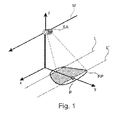
- FIG. 1 illustrates the principle of SAR measurement based on the radar emitted by a satellite radar.
- the in Fig. 1 shown satellite is indicated by the reference symbol SA and moves in the direction of the arrow M, which corresponds to the x-direction of the in Fig. 1 corresponds to the Cartesian coordinate system. This x-direction represents the azimuth direction.
- the satellite SA whose height above the earth's surface is represented by the z-coordinate of the coordinate system, continuously emits radar pulses via a transmitting antenna towards the earth's surface during its motion, the contour of a straight emitted radar pulse on the earth's surface is denoted by RP.
- the radar echo is detected by the reflected radar radiation at the earth's surface in the range direction y of the Cartesian coordinate system with a receiver (not Fig. 1 apparent) is timed.
- the Fig. 1 It is a monostatic radar system with transmitter and receiver on the same platform.
- a radar pulse for a range position.
- the assignment of a key value to a radar pulse is represented by the azimuth position in the x direction.
- Data acquisition thus represents a two-dimensional matrix of scanning values in the azimuth direction and the range direction.
- a key value is a complex value with a corresponding amplitude and phase.
- Fig. 1 only information of the radar radiation between the two lines L and L 'are detected, which have a distance of several kilometers (eg 30 km). This is also indicated by the hatched area, which overlaps the contour RP of the illumination zone of the transmitting antenna.
- the detection of the radar echo leads to a phase modulation which can be suitably processed, which finally results in amplitude and phase information and thus a pixel of the earth's surface for the points on the earth's surface where the radar pulses are reflected ,
- the corresponding calculation of pixels of the earth's surface from the data acquisition described above is well known to the person skilled in the art and will therefore not be explained in further detail.
- a large number of radar pulses of a small aperture radar transmitter simulate a larger synthetic aperture corresponding to the extent of the radar pulse on the earth's surface.
- two data acquisitions detected by corresponding satellites are processed in such a way that missing sample values of a data acquisition are reconstructed by corresponding sample values of the other data acquisition. It is considered a monostatic SAR radar system with two satellites, which separately emit radar pulses and receive their echoes. Nonetheless, the invention is also applicable to a bistatic SAR radar system in which the radar pulses are transmitted from one satellite and received by another satellite.
- Fig. 2 shows an example of a monostatic SAR radar system with the two satellites SA1 and SA2, which move in the same azimuth direction M offset from each other.
- the satellites are offset in azimuth direction as well as in range direction.
- the speed of the two satellites is the same and is v sat .
- a first data acquisition DA1 is obtained in the form of probing values along the azimuth direction x and the range direction y.
- a second data acquisition DA2 is generated by the satellite SA2 with corresponding probing values in the azimuth and range direction.
- the data acquisition for the data acquisition DA1 is interrupted at a time t1 and for the data acquisition DA2 for a time t2, wherein the respective radar echo along the corresponding azimuth at the respective times or periods Position has failed.
- the time difference between the missing samples is denoted by ⁇ t a, gaps .
- the time ⁇ t a and the time ⁇ t a, gaps are chosen such that samples missing in the data acquisition DA1 concern other reflection positions on the earth surface, such as the missing samples of the data acquisition DA2. Consequently, it is possible with the method according to the invention to replace the missing samples of a data acquisition by the samples of the other data acquisition. In a multistatic SAR radar system comprising two or more platforms, this may, for example, enable a reduction in the pulse repetition rate of the radar pulses, thereby improving the performance of the system.
- Two-dimensional and / or three-dimensional digital images of the earth's surface are then calculated from the first data acquisition with the replaced sampling values, optionally in combination with the second data acquisition.
- the calculation of such images is known per se for SAR systems and will therefore not be explained in detail.
- three-dimensional images are determined by (computer-aided) interferometric superposition of two two-dimensional images, wherein a two-dimensional image was obtained from the first data acquisition with correspondingly replaced samples and the other two-dimensional image was obtained from the second data acquisition. From the two two-dimensional images can in a conventional manner a Height information is derived, which is then included in the corresponding three-dimensional image.
- GC Geometry Compensation
- a geometric compensation is performed, which is composed of a geometric reconstruction GR and a range-dependent bandpass filtering FI.
- a reconstructed sample value of samples of the data acquisition DA2 is determined with positions corresponding to reflection positions on the earth surface of radar returns which contribute to the missing sample value.
- Fig. 4 clarified.
- Fig. 4 shows a plan view of the earth's surface with azimuth positions in the x-direction and range positions in the y-direction.
- the position of the satellite SA1 is indicated by P SA1 .
- the radar returns from all positions along the isorange line IR m contribute to the duty value according to the range position r m, 0 from the data acquisition DA1.
- This line represents the intersection of a sphere with center point P SA1 and a radius corresponding to position r m, 0 with the surface of the earth.
- the illustrated segment of the isorange line corresponds to the aperture of the radar receiver.
- the position of the satellite SA2 at the time when this satellite is at the same azimuth position as the satellite SA1 is designated P SA2 .
- the distance between the two satellite positions in the range direction is denoted by b ms . Due to the offset of the satellites in the range direction, the reflection positions on the earth's surface are in the data acquisition DA2 which corresponds to the duty value of the first data acquisition DA1 at the range position r m, 0 contribute, between the two isorange lines IR S and IR S ' , which are spaced apart by the distance ⁇ r s, 0 .
- the isorange line IR S is the intersection of a sphere with a center P SA2 and a radius corresponding to the range position r s, 0 with the surface of the earth, where r s, 0 is the smallest distance of the isorange line IR m from the point P SA2 corresponds.
- the isorange line IR S ' is the intersection of a sphere with center P SA2 and a radius corresponding to the range position (r s, 0 + ⁇ r s, 0 ) with the earth's surface, where (r s, 0 + ⁇ r s, 0 ) corresponds to the largest distance of the isorange line IR m from the point P SA2 .
- the samples of the second data acquisition DA2 in the range interval ⁇ r s, 0 must be considered.
- the energy distributed over the interval [r s, 0 , r s, 0 + ⁇ r s, 0 ] must be refocused.
- r m, 0 is the range position of the missing sample and thus also of the reconstructed sample d m, GR ; wherein r s represent the range positions according to the second data acquisition DA2 and d s (r s ) are interpolated second samples of the second data acquisition for the predetermined azimuth position (ie, the azimuth position of the second data acquisition corresponding to the predetermined azimuth position ), which is integrated over the range positions r s , which correspond to reflection positions on the earth's surface of radar echoes that contribute to the missing key value d m , ie it is in the example of the Fig. 4 over the interval [r s, 0 ; r s, 0 + ⁇ r s, 0 ] integrated; where ⁇ is the wavelength of the radar radiation of the SAR radar system.
- a range-dependent filtering FI is performed to eliminate additional noise outside the common range bandwidth between the samples of the first and second data acquisition.
- a spectral frequency shift occurs in respective pixels of the SAR images, which is described by the equation (6) of the document [1].
- r m, 0 again denotes the range position of the missing sample value of the first data acquisition
- h ss is the above-defined pulse response of the bandpass filter, which depends on the position r m, 0 .
- the convolution along the range positions r m of the first data acquisition DA1 is represented.
- a system calibration SC is carried out in which the possibly different acquisition systems are adapted to one another. That is, different characteristics of the radar SA1 and the radar SA2 are appropriately compensated using available calibration information about the systems.
- calibration information is known per se and may include constant and possibly also time-variable factors that determine the status of the radar systems, their antennas as well as thermal and temporal drifts, bandwidths, etc.
- r m, 0 again denotes the range position of the missing sample value of the first data acquisition and by * the convolution along the range positions r m of the first data acquisition DA1 is described.
- the function C sys is a complex pulse-response function for the echo, which reflects the different behavior of the two acquisition systems.
- the definition of a corresponding impulse response function may be appropriately defined by those skilled in the art based on known different characteristics of the radar systems.
- the two data acquisitions DA1 and DA2 differ only in a constant amplitude and phase offset.
- the function C sys can be represented by k ⁇ (r m -r m, 0 ) , where ⁇ ( ⁇ ) is the Dirac function. Should the amplitude and phase offset vary for different azimuth positions, but be constant for the range positions along an azimuth position, the value of the factor k depends on the azimuth position.
- the definition of other pulse-response functions C sys with other characteristics of radar systems is within the scope of expert action.
- a so-called autofocus AF is finally applied to the samples d m, SC .
- This autofocus takes into account residual errors, which may also be present after the system calibration.
- the residual errors can be caused by errors in the geometric compensation GC as well as in the system calibration SC.
- r m, 0 again denotes the range position of the missing sample value of the first data acquisition and by * the convolution along the range positions r m of the first data acquisition DA1 is described.
- the method used in Reference [2] can be used.
- the above correction can thus be carried out by a method known per se.
- other known techniques may also be used for autofocus step AF, such as contrast maximization, map drifts, model matching, and the like.
- a SAR image can then be determined.
- the method can also be used for missing sample values of the second data acquisition DA2, which are characterized by corresponding sample values of the first data acquisition with the steps Fig. 3 be reconstructed.
- the method according to the invention was tested on the basis of real SAR data of an area on the earth's surface.
- Two SAR images were determined in the form of interferograms based on two data acquisitions of a bistatic SAR system.
- An SAR image was based on data acquisitions with missing samples that were not reconstructed.
- the other SAR image was reconstructed.
- Fig. 5 For a differential interferogram obtained from data acquisitions without reconstructed samples, the range-direction-averaged differential phase ⁇ is plotted along the azimuth x. Ideally, this phase should be at 0 °. This is however in Fig. 5 not the case. Rather, there are larger fluctuations in the phase.
- Fig. 6 shows the same diagram as Fig. 5
- the differential interferogram was determined using the reconstruction of samples according to the invention.
- the fluctuations in the phase are much lower and are very close to the ideal phase value of 0 °.
- the Reconstruction according to the invention can thus be obtained SAR images with improved image quality.
- the embodiments of the invention described above have a number of advantages.
- it is easy to reconstruct missing samples in a SAR data acquisition based on samples of another data acquisition.
- SAR images with improved quality can be generated, the method provides good results for both homogeneous surfaces and punctiform scattering objects.
Landscapes
- Engineering & Computer Science (AREA)
- Remote Sensing (AREA)
- Radar, Positioning & Navigation (AREA)
- Physics & Mathematics (AREA)
- Computer Networks & Wireless Communication (AREA)
- General Physics & Mathematics (AREA)
- Electromagnetism (AREA)
- Radar Systems Or Details Thereof (AREA)
Applications Claiming Priority (1)
| Application Number | Priority Date | Filing Date | Title |
|---|---|---|---|
| DE102013213304.9A DE102013213304B3 (de) | 2013-07-08 | 2013-07-08 | Verfahren zur rechnergestützten Verarbeitung von SAR-Daten |
Publications (2)
| Publication Number | Publication Date |
|---|---|
| EP2829892A1 true EP2829892A1 (fr) | 2015-01-28 |
| EP2829892B1 EP2829892B1 (fr) | 2019-02-13 |
Family
ID=51022784
Family Applications (1)
| Application Number | Title | Priority Date | Filing Date |
|---|---|---|---|
| EP14175418.4A Active EP2829892B1 (fr) | 2013-07-08 | 2014-07-02 | Procédé de traitement assisté par ordinateur de données RSO |
Country Status (2)
| Country | Link |
|---|---|
| EP (1) | EP2829892B1 (fr) |
| DE (1) | DE102013213304B3 (fr) |
Cited By (1)
| Publication number | Priority date | Publication date | Assignee | Title |
|---|---|---|---|---|
| CN111429390A (zh) * | 2020-03-18 | 2020-07-17 | 江西师范大学 | 一种地面系统遥感图像的自适应实时处理方法 |
-
2013
- 2013-07-08 DE DE102013213304.9A patent/DE102013213304B3/de active Active
-
2014
- 2014-07-02 EP EP14175418.4A patent/EP2829892B1/fr active Active
Non-Patent Citations (8)
| Title |
|---|
| DEREGOWSKI S M ET AL: "GEOMETRICAL OPTICS AND WAVE THEORY OF CONSTANT OFFSET SECTIONS IN LAYERED MEDIA", GEOPHYSICAL PROSPECTING, OXFORD, GB, vol. 29, 1 January 1981 (1981-01-01), pages 374 - 406, XP000618120 * |
| F. GATELLI; A. MONTI GUARNIERI; F. PARIZZI; P. PASQUALI; C. PRATI; F. ROCCA, THE WAVENUMBER SHIFT IN SAR INTERFEROMETRY, vol. 32, no. 4, 1994, pages 855 - 865 |
| G BOLONDI ET AL: "Offset Continuation in Theory and Practice", GEOPHYSICAL PROSPECTING, vol. 32, 1 January 1984 (1984-01-01), pages 1045 - 1073, XP055158744 * |
| J. SALZMAN; D. AKAMINE; R. LEFEVRE; J. C. KIRK, JR.: "Interrupted synthetic aperture radar (SAR", IEEE TRANSACTIONS ON AEROSPACE AND ELECTRONIC SYSTEMS, vol. 17, no. 5, May 2002 (2002-05-01), pages 33 - 39, XP011092453 |
| KRIEGER G ET AL: "SAR signal reconstruction from non-uniform displaced phase centre sampling", GEOSCIENCE AND REMOTE SENSING SYMPOSIUM, 2004. IGARSS '04. PROCEEDINGS . 2004 IEEE INTERNATIONAL ANCHORAGE, AK, USA 20-24 SEPT. 2004, PISCATAWAY, NJ, USA,IEEE, vol. 3, 20 September 2004 (2004-09-20), pages 1763 - 1766, XP010751954, ISBN: 978-0-7803-8742-3, DOI: 10.1109/IGARSS.2004.1370674 * |
| LIU Y ET AL: "Signal model and imaging algorithm for spaceborne interrupted continuous-wave synthetic aperture radar", IET RADAR SONAR NAVIGATION, THE INSTITUTION OF ENGINEERING AND TECHNOLOGY, UK, vol. 6, no. 5, 1 June 2012 (2012-06-01), pages 348 - 358, XP006041836, ISSN: 1751-8784, DOI: 10.1049/IET-RSN.2011.0287 * |
| TAO LAI ET AL: "Achieving HRWS Images with Space-borne Bistatic SAR with Multiple Phase Centers", GEOSCIENCE AND REMOTE SENSING SYMPOSIUM, 2008. IGARSS 2008. IEEE INTERNATIONAL, IEEE, PISCATAWAY, NJ, USA, 7 July 2008 (2008-07-07), pages V - 180, XP031423190, ISBN: 978-1-4244-2807-6 * |
| YI JIANG ET AL: "Study on time domain reconstruction from non-uniform azimuth sampling in SAR signal", 2007 1ST ASIAN AND PACIFIC CONFERENCE ON SYNTHETIC APERTURE RADAR, 1 November 2007 (2007-11-01), pages 725 - 728, XP055158752, ISBN: 978-1-42-441188-7, DOI: 10.1109/APSAR.2007.4418714 * |
Cited By (2)
| Publication number | Priority date | Publication date | Assignee | Title |
|---|---|---|---|---|
| CN111429390A (zh) * | 2020-03-18 | 2020-07-17 | 江西师范大学 | 一种地面系统遥感图像的自适应实时处理方法 |
| CN111429390B (zh) * | 2020-03-18 | 2023-10-13 | 江西师范大学 | 一种地面系统遥感图像的自适应实时处理方法 |
Also Published As
| Publication number | Publication date |
|---|---|
| DE102013213304B3 (de) | 2014-09-04 |
| EP2829892B1 (fr) | 2019-02-13 |
Similar Documents
| Publication | Publication Date | Title |
|---|---|---|
| EP3803454B1 (fr) | Procédé radar à ouverture synthetique et dispositif radar à ouverture synthetique | |
| EP3385750B1 (fr) | Procédé et dispositif de traitement de données brutes sar | |
| EP2875384B1 (fr) | Procédé de traitement de données brutes d'un radar rso en mode de saisie hyperfine obtenues en haute résolution et à protection spatiale | |
| EP2843439B1 (fr) | Procédé de correction de références de phase et de temps de données SAR non synchrones | |
| DE102006009121B4 (de) | Verfahren zur Verarbeitung und Darstellung von mittels Synthetik-Apertur-Radarsystemen (SAR) gewonnen Bodenbildern | |
| EP4211490A1 (fr) | Procédé, système radar et véhicule pour le traitement de signaux radars | |
| DE102009057191A1 (de) | Verfahren zum eindeutigen Bestimmen einer Entfernung und/oder einer relativen Geschwindigkeit eines Objektes, Fahrerassistenzeinrichtung und Kraftfahrzeug | |
| EP0795762A2 (fr) | Procédé de mise à l'échelle de l'azimut pour données SAR et processeur à grande précision pour traitement des données SCAN-SAR | |
| EP3060939B1 (fr) | Procédé radar à synthèse d'ouverture | |
| DE102012021010A1 (de) | Synthetisches Apertur Radar zur gleichzeitigen Bildaufnahme und Bewegtzielerkennung | |
| WO2008119455A1 (fr) | Procédé d'exploration d'une zone glaciaire ou d'une zone sèche par échosondage par radar | |
| EP4196818B1 (fr) | Procédé et dispositif permettant de déterminer des perturbations de fréquence dans un signal reçu d'un système sar à canaux multiples actif | |
| EP1637902B1 (fr) | Système et dispositif de mesure radar interférometrique | |
| DE102013216461A1 (de) | Synthetik-Apertur-Radarverfahren | |
| EP3019887A1 (fr) | Détermination d'une position d'un récepteur mobile | |
| EP1536247A1 (fr) | Procédé interférométrique de radar à micro-ondes | |
| DE102022208465A1 (de) | Verfahren zur Korrektur eines Radarsignals zum Bestimmen einer synthetischen Apertur, Computerprogramm, Vorrichtung und Fahrzeug | |
| EP2829892B1 (fr) | Procédé de traitement assisté par ordinateur de données RSO | |
| DE102012219225B4 (de) | Synthetik-Apertur-Radarverfahren und Synthetik-Apertur-Radarvorrichtung | |
| DE102024109490B3 (de) | Verfahren und Vorrichtung zur rechnergestützten Verarbeitung eines SAR-Bilds | |
| DE102022133858B4 (de) | Verfahren zur rechnergestützten Verarbeitung von SAR-Rohdaten | |
| DE102011016337B4 (de) | Verfahren und Vorrichtung zur Abbildung von mit Clutter überlagerten bewegten Objekten mit Radar oder Sonar | |
| EP4492091A1 (fr) | Procédé d'estimation et de correction de références de phase et de temps de données sar non synchrones d'un système sar multicanal | |
| DE102022117088A1 (de) | Verfahren zur Erkennung und Auflösung von Phasenmehrdeutigkeiten in interferometrischen SAR-Daten | |
| DE102018124582A1 (de) | Verfahren zur Erfassung bei einem Radarsystem |
Legal Events
| Date | Code | Title | Description |
|---|---|---|---|
| 17P | Request for examination filed |
Effective date: 20140702 |
|
| AK | Designated contracting states |
Kind code of ref document: A1 Designated state(s): AL AT BE BG CH CY CZ DE DK EE ES FI FR GB GR HR HU IE IS IT LI LT LU LV MC MK MT NL NO PL PT RO RS SE SI SK SM TR |
|
| AX | Request for extension of the european patent |
Extension state: BA ME |
|
| PUAI | Public reference made under article 153(3) epc to a published international application that has entered the european phase |
Free format text: ORIGINAL CODE: 0009012 |
|
| R17P | Request for examination filed (corrected) |
Effective date: 20150723 |
|
| RBV | Designated contracting states (corrected) |
Designated state(s): AL AT BE BG CH CY CZ DE DK EE ES FI FR GB GR HR HU IE IS IT LI LT LU LV MC MK MT NL NO PL PT RO RS SE SI SK SM TR |
|
| STAA | Information on the status of an ep patent application or granted ep patent |
Free format text: STATUS: EXAMINATION IS IN PROGRESS |
|
| 17Q | First examination report despatched |
Effective date: 20170410 |
|
| RBV | Designated contracting states (corrected) |
Designated state(s): AL AT BE BG CH CY CZ DK EE ES FI FR GB GR HR HU IE IS IT LI LT LU LV MC MK MT NL NO PL PT RO RS SE SI SK SM TR |
|
| REG | Reference to a national code |
Ref country code: DE Ref legal event code: R108 |
|
| GRAJ | Information related to disapproval of communication of intention to grant by the applicant or resumption of examination proceedings by the epo deleted |
Free format text: ORIGINAL CODE: EPIDOSDIGR1 |
|
| GRAP | Despatch of communication of intention to grant a patent |
Free format text: ORIGINAL CODE: EPIDOSNIGR1 |
|
| GRAP | Despatch of communication of intention to grant a patent |
Free format text: ORIGINAL CODE: EPIDOSNIGR1 |
|
| STAA | Information on the status of an ep patent application or granted ep patent |
Free format text: STATUS: GRANT OF PATENT IS INTENDED |
|
| INTG | Intention to grant announced |
Effective date: 20180921 |
|
| GRAS | Grant fee paid |
Free format text: ORIGINAL CODE: EPIDOSNIGR3 |
|
| GRAA | (expected) grant |
Free format text: ORIGINAL CODE: 0009210 |
|
| STAA | Information on the status of an ep patent application or granted ep patent |
Free format text: STATUS: THE PATENT HAS BEEN GRANTED |
|
| AK | Designated contracting states |
Kind code of ref document: B1 Designated state(s): AL AT BE BG CH CY CZ DK EE ES FI FR GB GR HR HU IE IS IT LI LT LU LV MC MK MT NL NO PL PT RO RS SE SI SK SM TR |
|
| REG | Reference to a national code |
Ref country code: GB Ref legal event code: FG4D Free format text: NOT ENGLISH |
|
| REG | Reference to a national code |
Ref country code: CH Ref legal event code: EP Ref country code: AT Ref legal event code: REF Ref document number: 1096541 Country of ref document: AT Kind code of ref document: T Effective date: 20190215 |
|
| REG | Reference to a national code |
Ref country code: IE Ref legal event code: FG4D Free format text: LANGUAGE OF EP DOCUMENT: GERMAN |
|
| REG | Reference to a national code |
Ref country code: LT Ref legal event code: MG4D |
|
| REG | Reference to a national code |
Ref country code: NL Ref legal event code: MP Effective date: 20190213 |
|
| PG25 | Lapsed in a contracting state [announced via postgrant information from national office to epo] |
Ref country code: FI Free format text: LAPSE BECAUSE OF FAILURE TO SUBMIT A TRANSLATION OF THE DESCRIPTION OR TO PAY THE FEE WITHIN THE PRESCRIBED TIME-LIMIT Effective date: 20190213 Ref country code: NO Free format text: LAPSE BECAUSE OF FAILURE TO SUBMIT A TRANSLATION OF THE DESCRIPTION OR TO PAY THE FEE WITHIN THE PRESCRIBED TIME-LIMIT Effective date: 20190513 Ref country code: SE Free format text: LAPSE BECAUSE OF FAILURE TO SUBMIT A TRANSLATION OF THE DESCRIPTION OR TO PAY THE FEE WITHIN THE PRESCRIBED TIME-LIMIT Effective date: 20190213 Ref country code: LT Free format text: LAPSE BECAUSE OF FAILURE TO SUBMIT A TRANSLATION OF THE DESCRIPTION OR TO PAY THE FEE WITHIN THE PRESCRIBED TIME-LIMIT Effective date: 20190213 Ref country code: PT Free format text: LAPSE BECAUSE OF FAILURE TO SUBMIT A TRANSLATION OF THE DESCRIPTION OR TO PAY THE FEE WITHIN THE PRESCRIBED TIME-LIMIT Effective date: 20190613 Ref country code: NL Free format text: LAPSE BECAUSE OF FAILURE TO SUBMIT A TRANSLATION OF THE DESCRIPTION OR TO PAY THE FEE WITHIN THE PRESCRIBED TIME-LIMIT Effective date: 20190213 |
|
| PG25 | Lapsed in a contracting state [announced via postgrant information from national office to epo] |
Ref country code: RS Free format text: LAPSE BECAUSE OF FAILURE TO SUBMIT A TRANSLATION OF THE DESCRIPTION OR TO PAY THE FEE WITHIN THE PRESCRIBED TIME-LIMIT Effective date: 20190213 Ref country code: LV Free format text: LAPSE BECAUSE OF FAILURE TO SUBMIT A TRANSLATION OF THE DESCRIPTION OR TO PAY THE FEE WITHIN THE PRESCRIBED TIME-LIMIT Effective date: 20190213 Ref country code: BG Free format text: LAPSE BECAUSE OF FAILURE TO SUBMIT A TRANSLATION OF THE DESCRIPTION OR TO PAY THE FEE WITHIN THE PRESCRIBED TIME-LIMIT Effective date: 20190513 Ref country code: IS Free format text: LAPSE BECAUSE OF FAILURE TO SUBMIT A TRANSLATION OF THE DESCRIPTION OR TO PAY THE FEE WITHIN THE PRESCRIBED TIME-LIMIT Effective date: 20190613 Ref country code: GR Free format text: LAPSE BECAUSE OF FAILURE TO SUBMIT A TRANSLATION OF THE DESCRIPTION OR TO PAY THE FEE WITHIN THE PRESCRIBED TIME-LIMIT Effective date: 20190514 Ref country code: HR Free format text: LAPSE BECAUSE OF FAILURE TO SUBMIT A TRANSLATION OF THE DESCRIPTION OR TO PAY THE FEE WITHIN THE PRESCRIBED TIME-LIMIT Effective date: 20190213 |
|
| PG25 | Lapsed in a contracting state [announced via postgrant information from national office to epo] |
Ref country code: EE Free format text: LAPSE BECAUSE OF FAILURE TO SUBMIT A TRANSLATION OF THE DESCRIPTION OR TO PAY THE FEE WITHIN THE PRESCRIBED TIME-LIMIT Effective date: 20190213 Ref country code: DK Free format text: LAPSE BECAUSE OF FAILURE TO SUBMIT A TRANSLATION OF THE DESCRIPTION OR TO PAY THE FEE WITHIN THE PRESCRIBED TIME-LIMIT Effective date: 20190213 Ref country code: SK Free format text: LAPSE BECAUSE OF FAILURE TO SUBMIT A TRANSLATION OF THE DESCRIPTION OR TO PAY THE FEE WITHIN THE PRESCRIBED TIME-LIMIT Effective date: 20190213 Ref country code: AL Free format text: LAPSE BECAUSE OF FAILURE TO SUBMIT A TRANSLATION OF THE DESCRIPTION OR TO PAY THE FEE WITHIN THE PRESCRIBED TIME-LIMIT Effective date: 20190213 Ref country code: IT Free format text: LAPSE BECAUSE OF FAILURE TO SUBMIT A TRANSLATION OF THE DESCRIPTION OR TO PAY THE FEE WITHIN THE PRESCRIBED TIME-LIMIT Effective date: 20190213 Ref country code: ES Free format text: LAPSE BECAUSE OF FAILURE TO SUBMIT A TRANSLATION OF THE DESCRIPTION OR TO PAY THE FEE WITHIN THE PRESCRIBED TIME-LIMIT Effective date: 20190213 Ref country code: RO Free format text: LAPSE BECAUSE OF FAILURE TO SUBMIT A TRANSLATION OF THE DESCRIPTION OR TO PAY THE FEE WITHIN THE PRESCRIBED TIME-LIMIT Effective date: 20190213 Ref country code: CZ Free format text: LAPSE BECAUSE OF FAILURE TO SUBMIT A TRANSLATION OF THE DESCRIPTION OR TO PAY THE FEE WITHIN THE PRESCRIBED TIME-LIMIT Effective date: 20190213 |
|
| PG25 | Lapsed in a contracting state [announced via postgrant information from national office to epo] |
Ref country code: SM Free format text: LAPSE BECAUSE OF FAILURE TO SUBMIT A TRANSLATION OF THE DESCRIPTION OR TO PAY THE FEE WITHIN THE PRESCRIBED TIME-LIMIT Effective date: 20190213 Ref country code: PL Free format text: LAPSE BECAUSE OF FAILURE TO SUBMIT A TRANSLATION OF THE DESCRIPTION OR TO PAY THE FEE WITHIN THE PRESCRIBED TIME-LIMIT Effective date: 20190213 |
|
| PLBE | No opposition filed within time limit |
Free format text: ORIGINAL CODE: 0009261 |
|
| STAA | Information on the status of an ep patent application or granted ep patent |
Free format text: STATUS: NO OPPOSITION FILED WITHIN TIME LIMIT |
|
| 26N | No opposition filed |
Effective date: 20191114 |
|
| PG25 | Lapsed in a contracting state [announced via postgrant information from national office to epo] |
Ref country code: MC Free format text: LAPSE BECAUSE OF FAILURE TO SUBMIT A TRANSLATION OF THE DESCRIPTION OR TO PAY THE FEE WITHIN THE PRESCRIBED TIME-LIMIT Effective date: 20190213 Ref country code: SI Free format text: LAPSE BECAUSE OF FAILURE TO SUBMIT A TRANSLATION OF THE DESCRIPTION OR TO PAY THE FEE WITHIN THE PRESCRIBED TIME-LIMIT Effective date: 20190213 |
|
| REG | Reference to a national code |
Ref country code: CH Ref legal event code: PL |
|
| GBPC | Gb: european patent ceased through non-payment of renewal fee |
Effective date: 20190702 |
|
| PG25 | Lapsed in a contracting state [announced via postgrant information from national office to epo] |
Ref country code: TR Free format text: LAPSE BECAUSE OF FAILURE TO SUBMIT A TRANSLATION OF THE DESCRIPTION OR TO PAY THE FEE WITHIN THE PRESCRIBED TIME-LIMIT Effective date: 20190213 |
|
| REG | Reference to a national code |
Ref country code: BE Ref legal event code: MM Effective date: 20190731 |
|
| PG25 | Lapsed in a contracting state [announced via postgrant information from national office to epo] |
Ref country code: GB Free format text: LAPSE BECAUSE OF NON-PAYMENT OF DUE FEES Effective date: 20190702 |
|
| PG25 | Lapsed in a contracting state [announced via postgrant information from national office to epo] |
Ref country code: BE Free format text: LAPSE BECAUSE OF NON-PAYMENT OF DUE FEES Effective date: 20190731 Ref country code: LU Free format text: LAPSE BECAUSE OF NON-PAYMENT OF DUE FEES Effective date: 20190702 Ref country code: CH Free format text: LAPSE BECAUSE OF NON-PAYMENT OF DUE FEES Effective date: 20190731 Ref country code: LI Free format text: LAPSE BECAUSE OF NON-PAYMENT OF DUE FEES Effective date: 20190731 |
|
| PG25 | Lapsed in a contracting state [announced via postgrant information from national office to epo] |
Ref country code: IE Free format text: LAPSE BECAUSE OF NON-PAYMENT OF DUE FEES Effective date: 20190702 |
|
| REG | Reference to a national code |
Ref country code: AT Ref legal event code: MM01 Ref document number: 1096541 Country of ref document: AT Kind code of ref document: T Effective date: 20190702 |
|
| PG25 | Lapsed in a contracting state [announced via postgrant information from national office to epo] |
Ref country code: AT Free format text: LAPSE BECAUSE OF NON-PAYMENT OF DUE FEES Effective date: 20190702 |
|
| PG25 | Lapsed in a contracting state [announced via postgrant information from national office to epo] |
Ref country code: CY Free format text: LAPSE BECAUSE OF FAILURE TO SUBMIT A TRANSLATION OF THE DESCRIPTION OR TO PAY THE FEE WITHIN THE PRESCRIBED TIME-LIMIT Effective date: 20190213 |
|
| PG25 | Lapsed in a contracting state [announced via postgrant information from national office to epo] |
Ref country code: MT Free format text: LAPSE BECAUSE OF FAILURE TO SUBMIT A TRANSLATION OF THE DESCRIPTION OR TO PAY THE FEE WITHIN THE PRESCRIBED TIME-LIMIT Effective date: 20190213 Ref country code: HU Free format text: LAPSE BECAUSE OF FAILURE TO SUBMIT A TRANSLATION OF THE DESCRIPTION OR TO PAY THE FEE WITHIN THE PRESCRIBED TIME-LIMIT; INVALID AB INITIO Effective date: 20140702 |
|
| PG25 | Lapsed in a contracting state [announced via postgrant information from national office to epo] |
Ref country code: MK Free format text: LAPSE BECAUSE OF FAILURE TO SUBMIT A TRANSLATION OF THE DESCRIPTION OR TO PAY THE FEE WITHIN THE PRESCRIBED TIME-LIMIT Effective date: 20190213 |
|
| PGFP | Annual fee paid to national office [announced via postgrant information from national office to epo] |
Ref country code: FR Payment date: 20250612 Year of fee payment: 12 |