EP2833070A1 - Bougie à incandescence et son procédé de fabrication - Google Patents
Bougie à incandescence et son procédé de fabrication Download PDFInfo
- Publication number
- EP2833070A1 EP2833070A1 EP13768466.8A EP13768466A EP2833070A1 EP 2833070 A1 EP2833070 A1 EP 2833070A1 EP 13768466 A EP13768466 A EP 13768466A EP 2833070 A1 EP2833070 A1 EP 2833070A1
- Authority
- EP
- European Patent Office
- Prior art keywords
- tool engagement
- engagement portion
- housing
- glow plug
- shape
- Prior art date
- Legal status (The legal status is an assumption and is not a legal conclusion. Google has not performed a legal analysis and makes no representation as to the accuracy of the status listed.)
- Withdrawn
Links
- 238000004519 manufacturing process Methods 0.000 title claims abstract description 21
- 238000000034 method Methods 0.000 title claims description 21
- 238000002485 combustion reaction Methods 0.000 claims abstract description 16
- 239000013067 intermediate product Substances 0.000 claims description 21
- 239000007769 metal material Substances 0.000 claims description 13
- 230000008569 process Effects 0.000 claims description 8
- 230000006872 improvement Effects 0.000 abstract description 13
- 230000009467 reduction Effects 0.000 abstract description 13
- 239000000446 fuel Substances 0.000 abstract description 12
- 238000010438 heat treatment Methods 0.000 description 38
- 230000001965 increasing effect Effects 0.000 description 9
- XEEYBQQBJWHFJM-UHFFFAOYSA-N Iron Chemical compound [Fe] XEEYBQQBJWHFJM-UHFFFAOYSA-N 0.000 description 7
- 229910052751 metal Inorganic materials 0.000 description 7
- 239000002184 metal Substances 0.000 description 7
- PXHVJJICTQNCMI-UHFFFAOYSA-N Nickel Chemical compound [Ni] PXHVJJICTQNCMI-UHFFFAOYSA-N 0.000 description 6
- 229910045601 alloy Inorganic materials 0.000 description 6
- 239000000956 alloy Substances 0.000 description 6
- 239000000919 ceramic Substances 0.000 description 5
- 238000009413 insulation Methods 0.000 description 5
- 239000000463 material Substances 0.000 description 5
- 239000000203 mixture Substances 0.000 description 5
- 238000005520 cutting process Methods 0.000 description 4
- 239000000843 powder Substances 0.000 description 4
- 238000005242 forging Methods 0.000 description 3
- 229910052759 nickel Inorganic materials 0.000 description 3
- 238000003825 pressing Methods 0.000 description 3
- 229910003271 Ni-Fe Inorganic materials 0.000 description 2
- 229910052804 chromium Inorganic materials 0.000 description 2
- 229920001971 elastomer Polymers 0.000 description 2
- 229920001973 fluoroelastomer Polymers 0.000 description 2
- 229910052742 iron Inorganic materials 0.000 description 2
- 229920002379 silicone rubber Polymers 0.000 description 2
- 239000004945 silicone rubber Substances 0.000 description 2
- 239000007787 solid Substances 0.000 description 2
- 238000003466 welding Methods 0.000 description 2
- 230000003245 working effect Effects 0.000 description 2
- 229910000975 Carbon steel Inorganic materials 0.000 description 1
- 230000009471 action Effects 0.000 description 1
- 230000008901 benefit Effects 0.000 description 1
- 239000010962 carbon steel Substances 0.000 description 1
- 239000010941 cobalt Substances 0.000 description 1
- 229910017052 cobalt Inorganic materials 0.000 description 1
- GUTLYIVDDKVIGB-UHFFFAOYSA-N cobalt atom Chemical compound [Co] GUTLYIVDDKVIGB-UHFFFAOYSA-N 0.000 description 1
- 238000007796 conventional method Methods 0.000 description 1
- 238000002788 crimping Methods 0.000 description 1
- 230000002708 enhancing effect Effects 0.000 description 1
- 239000011810 insulating material Substances 0.000 description 1
- 239000012774 insulation material Substances 0.000 description 1
- CPLXHLVBOLITMK-UHFFFAOYSA-N magnesium oxide Inorganic materials [Mg]=O CPLXHLVBOLITMK-UHFFFAOYSA-N 0.000 description 1
- 239000000395 magnesium oxide Substances 0.000 description 1
- AXZKOIWUVFPNLO-UHFFFAOYSA-N magnesium;oxygen(2-) Chemical compound [O-2].[Mg+2] AXZKOIWUVFPNLO-UHFFFAOYSA-N 0.000 description 1
- 230000000630 rising effect Effects 0.000 description 1
- 238000005096 rolling process Methods 0.000 description 1
- 229910001220 stainless steel Inorganic materials 0.000 description 1
- 239000010935 stainless steel Substances 0.000 description 1
- 229910001256 stainless steel alloy Inorganic materials 0.000 description 1
- 230000007704 transition Effects 0.000 description 1
- WFKWXMTUELFFGS-UHFFFAOYSA-N tungsten Chemical compound [W] WFKWXMTUELFFGS-UHFFFAOYSA-N 0.000 description 1
- 229910052721 tungsten Inorganic materials 0.000 description 1
- 239000010937 tungsten Substances 0.000 description 1
- 238000004804 winding Methods 0.000 description 1
Images




Classifications
-
- F—MECHANICAL ENGINEERING; LIGHTING; HEATING; WEAPONS; BLASTING
- F23—COMBUSTION APPARATUS; COMBUSTION PROCESSES
- F23Q—IGNITION; EXTINGUISHING-DEVICES
- F23Q7/00—Incandescent ignition; Igniters using electrically-produced heat, e.g. lighters for cigarettes; Electrically-heated glowing plugs
- F23Q7/001—Glowing plugs for internal-combustion engines
-
- B—PERFORMING OPERATIONS; TRANSPORTING
- B21—MECHANICAL METAL-WORKING WITHOUT ESSENTIALLY REMOVING MATERIAL; PUNCHING METAL
- B21D—WORKING OR PROCESSING OF SHEET METAL OR METAL TUBES, RODS OR PROFILES WITHOUT ESSENTIALLY REMOVING MATERIAL; PUNCHING METAL
- B21D22/00—Shaping without cutting, by stamping, spinning, or deep-drawing
- B21D22/20—Deep-drawing
-
- F—MECHANICAL ENGINEERING; LIGHTING; HEATING; WEAPONS; BLASTING
- F23—COMBUSTION APPARATUS; COMBUSTION PROCESSES
- F23Q—IGNITION; EXTINGUISHING-DEVICES
- F23Q7/00—Incandescent ignition; Igniters using electrically-produced heat, e.g. lighters for cigarettes; Electrically-heated glowing plugs
- F23Q7/001—Glowing plugs for internal-combustion engines
- F23Q2007/004—Manufacturing or assembling methods
Definitions
- the present invention relates to a glow plug used to preheat a diesel engine and the like, and a method for manufacturing the same.
- Glow plugs which are used in assisting a start of an internal combustion engine such as a diesel engine include a tubular housing, a heater member which is energized to be heated, and the like.
- a heater member which is energized to be heated
- the housing has a screw portion for being screwed into a mounting hole of the internal combustion engine and a tool engagement portion to which a tool engaged when being mounted to the internal combustion engine.
- An outer circumference of the tool engagement portion has a shape which allows the engagement of a tool such as a wrench, such as a hexagonal shape in cross section, whereby when the glow plug is mounted to the internal combustion engine, a force is applied along a circumferential direction of the tool engagement portion.
- an inner circumferential portion of such a tool engagement portion is formed into a circular shape in cross section by a cutting process, a forging process or the like. This is because, in a cutting process, a lathing operation is effected by means of a drill, a cutting bit or the like, and in a forging process, a round rod-like core metal is pushed into a rear end portion of the tool engagement portion (refer to, for example, Patent Literature 1).
- Patent Literature 1 JP-A-2010-210102
- the tool engagement portion since the circumferential force is applied to the tool engagement portion when the glow plug is mounted to the internal combustion engine, the tool engagement portion needs a mechanical strength by which the tool engagement portion is able to withstand the applied circumferential force. Because of this, the thickness of the tool engagement portion should be equal to or larger than a predetermined value.
- the tool engagement portion has the outer circumference which is formed into the hexagonal shape in cross section and the inner circumference which is formed into the circular shape in cross section
- the portions other than the thinnest portion of the tool engagement portion will be formed thicker than required. Consequently, the weight of the tool engagement portion and hence the weight of the housing becomes relatively large, as a result of which there is caused a fear that the fuel economy of the vehicle is deteriorated or the manufacturing cost of the glow plug is increased.
- the invention has been made in view of the situations described above, and an object thereof is to provide a glow plug which can realize an improvement in fuel economy or a reduction in manufacturing cost by reducing the weight of a tool engagement portion and hence the weight of a housing thereof, and a method for manufacturing the same.
- a glow plug according to this configuration is a glow plug including:
- the glow plug according to this configuration is characterized in that, in the above-described Configuration 1, in a cross-sectional plane perpendicular to the axis, an outer circumference of the tool engagement portion has a hexagonal shape, and any one of the following (a) to (c) is satisfied.
- the glow plug according to this configuration is characterized in that, in the above-described Configuration 1 or 2, the glow plug further includes:
- the glow plug according to this configuration is characterized in that, in any one of the above-described Configurations 1 to 3, the tool engagement portion has a uniform thickness.
- the description of "has a uniform thickness” includes not only a case where the respective thicknesses of the portions of the tool engagement portion are strictly the same but also a case where the respective thicknesses of the portions differ slightly (for example, by 0.5 mm or smaller).
- a method for manufacturing the glow plug according to this configuration is a method for manufacturing the spark plug described in any one of the above-described Configurations 1 to 4, the method including:
- the inner circumference of the tool engagement portion has a shape which follows the outer circumferential shape of the tool engagement portion (similar shapes in which apexes correspond to each other, and more particularly, when the outer circumference of the tool engagement portion is hexagonal in cross section, the inner circumference of the tool engagement portion also has a hexagonal shape in cross section which has sides parallel to sides of the hexagonal shape of the outer circumference of the tool engagement portion). Consequently, it is possible to prevent the thickness of the tool engagement portion from being increased locally, whereby the weight of the tool engagement portion and hence the weight of the housing can be reduced. As a result, it is possible to realize an improvement in fuel economy and a reduction in manufacturing cost.
- the tool engagement portion can be formed sufficiently thin, whereby the weight of the housing can be reduced further. Consequently, it is possible to realize more effectively the improvement in fuel economy and the reduction in manufacturing cost.
- the gastightness in the interior of the housing is ensured from time to time by providing an annular seal member between the inner circumference of the tool engagement portion and the outer circumference of the center pole and bringing the seal member into contact with a step portion which is provided on the inner circumference of the tool engagement portion.
- the inner circumference of the tool engagement portion is circular in cross section as in the conventional technique described above, it is very difficult to increase the area of the step portion while maintaining the strength of the tool engagement portion.
- the area of the projected region of the step portion can be 30% or larger of the area of the region which is surrounded by the projected line of the outer circumferential surface of the tool engagement portion. Consequently, the contact area of the seal member with the step portion can be increased very largely. As a result, an extremely good gastightness can be realized.
- the thickness of the tool engagement portion is uniform. Consequently, the tool engagement portion can be formed thin as a whole, and the weight of the housing can be reduced further. As a result, it is possible to realize more effectively the improvement in fuel economy and the reduction in manufacturing cost.
- the housing intermediate product which is to become the housing is manufactured by deep drawing processing. Consequently, the housing can be formed relatively thin as a whole, and the housing which is light in weight can be manufactured more easily. As a result, it is possible to realize an improvement in productivity.
- the housing can be made thin as a whole, it is possible to realize a further reduction in weight of the housing. As a result, it is possible to realize not only an improvement in fuel economy but also a reduction in manufacturing cost more effectively.
- Fig. 1 is a front view of a glow plug 1
- Fig. 2 is a partially cutaway front view of the glow plug 1.
- a direction of an axis CL1 of the glow plug 1 will be referred to as a vertical direction in the drawings, and a lower side will be referred to as a front end side, whereas an upper side will be referred to as a rear end side of the glow plug 1.
- the glow plug 1 includes a cylindrical housing 2 and a heater member 3 which is mounted to the housing 2.
- the housing 2 is formed of a predetermined metal (for example, carbon steel, stainless steel or the like) and has an axial hole 4 which penetrates therethrough in the direction of the axis CL1.
- the configuration of the tool engagement portion 6 will be described in detail later.
- the housing 2 includes a pressure contact portion 7 at a front end portion thereof which is brought into pressure contact with a seat surface (not shown) of the internal combustion engine when the screw portion 5 is screwed into the mounting hole.
- the pressure contact portion 7 has a tapered shape in which an outer diameter thereof gradually reduces as it extends towards the front end side, and gastightness is ensured in a combustion chamber by the pressure contact portion 7 being brought into pressure contact with the seat surface.
- the housing 2 includes a rear-end-side body portion 8 which is located between the screw portion 5 and the tool engagement portion 6 and a front-end-side body portion 9 which is located between the pressure contact portion 7 and the screw portion 5.
- the rear-end-side body portion 8 has a cylindrical shape and is configured so as to have a constant outer diameter along the direction of the axis CL1.
- the front-end-side body portion 9 is curved on an outer circumferential surface and an inner circumferential surface thereof, has a smallest hole diameter in the axial hole 4 and includes a holding portion 20 which holds the heater member 3 on the inner circumferential surface.
- the housing 2 is thin as a whole and has a substantially uniform thickness.
- the holding portion 20 has a smallest outer diameter in the front-end-side body portion 9.
- the heater member 3 includes a tube 10, as well as a heating coil 12 and a control coil 13 which are disposed in an inside of the tube 10 and is connected in series with a center pole 11 which is made of a predetermined metal (for example, an iron-based alloy or the like). Additionally, the heater member 3 is press fitted in the holding portion 20 with a front end portion thereof projecting from a front end of the housing 2 to thereby be fixed to the housing 2.
- a predetermined metal for example, an iron-based alloy or the like
- the tube 10 is formed of a metal which contains iron (Fe) or nickel (Ni) as a main composition (for example, a nickel-based alloy, a stainless steel alloy or the like) and is a cylindrical tube which is closed at a front end portion. Additionally, the heating coil 12 which is joined to a front end of the tube 10 at a front end portion thereof and the control coil 13 which is connected in series with a rear end portion of the heating coil 12 are sealed in an inside of the tube 10 together with insulation powder 14 which contains magnesium oxide powder. Although the heating coil 12 electrically conducts with the tube 10 at a front end thereof, outer circumferential surfaces of the heating coil 12 and the control coil 13 and an inner circumferential surface of the tube 10 are insulated from each other by the insulation powder 14 interposed therebetween.
- annular rubber 15 which is made of a predetermined rubber (for example, silicone rubber, fluororubber or the like) is provided between an inner circumference of a rear end side of the tube 10 and the center pole 11, whereby the interior of the tube 10 is sealed.
- a predetermined rubber for example, silicone rubber, fluororubber or the like
- the heating coil 12 is configured by winding a resistance heating wire which is made of a predetermined metal (for example, an alloy containing AL, Cr or the like in addition to Fe as a main composition, or the like) into a spiral shape.
- the heating coil 12 generates heat by being energized via the center pole 11.
- control coil 13 is made of a material having a larger temperature coefficient of an electric specific resistance than that of the material of which the heating coil 12 is made, for example, a resistance heating wire which contains as a main composition Co or Ni which is represented by a cobalt (Co)-Ni-Fe based alloy or the like.
- a resistance heating wire which contains as a main composition Co or Ni which is represented by a cobalt (Co)-Ni-Fe based alloy or the like.
- the control coil 13 increases an electric resistance value by generating heat in itself and receiving heat generated by the heating coil 12 therefrom to thereby control electric power supplied to the heating coil 12.
- a relatively large magnitude of electric power is supplied to the heating coil 12 at an initial stage of energization, whereby the temperature of the heating coil 12 is raised.
- the control coil 13 is heated as a result of the heating coil 12 being heated, and this increases the electric resistance value of the control coil 13, whereby the supply of electric power to the heating coil 12 is reduced.
- the temperature rising characteristic of the heater member 3 is such that the temperature of the heater member 3 rises quickly at the initial stage of energization, whereafter the temperature thereof does not increase any further by the supply of electric power being suppressed by the action of the control coil 13. Namely, the existence of the control coil 13 makes it difficult for an excessive rise (an overshoot) in temperature of the heating coil 12 to occur while enhancing the quick temperature raising characteristic of the heater member 3.
- the center pole 11 is formed as a solid rod-like member and a front end portion thereof is inserted into the interior of the tube 10. Then, with a frontmost end portion of the center pole 11 inserted in a rear end portion of the control coil 13, the center pole 11 and the control coil 13 are resistance welded together, whereby the center pole 11 and the control coil 13 are connected together.
- a cable connecting terminal pin 17 having a bottomed cylindrical shape is fixed to a rear end portion of the center pole 11 through crimping.
- an insulation bush 18 which is made of an insulation material is provided between a front end portion of the terminal pin 17 and a rear end portion of the housing 2 so as to prevent a direct energization (short-circuiting) between the terminal pin 17 and the housing 2.
- annular seal member 19 which is made of an insulating material (for example, silicone rubber, fluororubber or the like) and which is brought into contact with the housing 2 and the center pole 11, is provided between an inner circumference of the housing 2 (the tool engagement portion 6) and an outer circumference of the center pole 11 to realize an enhancement in gastightness in the axial hole 4 or the like.
- a step portion 16 is provided on the inner circumference of the housing 2 and this step portion 16 is located on an inner circumference of the tool engagement portion 6, projects radially inwards, and has an annular shape in which the axis CL1 serves as a center thereof.
- the seal member 19 is pressed towards the front end side in the direction of the axis C1 by the insulating bush 18 as the terminal pin 17 is crimped and fixed, whereby a surface of the seal member 19 which is located at the front end side in the direction of the axis CL1 is brought into pressure contact with the step portion 16.
- Fig. 3 is cross-sectional view taken along the line J-J in Fig. 2
- an inner circumference of the tool engagement portion 6 is formed into a hexagonal shape in cross section, which follows an outer circumferential shape of the tool engagement portion 6.
- the tool engagement portion 6 has a uniform thickness.
- a distance between opposite sides of the tool engagement portion 6 is 12 mm, and the thickness of the tool engagement portion 6 is 1.5 mm or smaller. Meanwhile, in the case where the distance between the opposite sides of the tool engagement portion 6 is 8 mm, the thickness of the tool engagement portion 6 is 0.8 mm or smaller. In the case where the distance between the opposite sides of the tool engagement portion 6 is 9 mm or 10 mm, the thickness of the tool engagement portion 6 is 1.0 mm or smaller. However, it is preferable that the thickness of the tool engagement portion 6 is a predetermined value (for example, 0.3 mm) or larger to ensure a sufficient mechanical strength for the tool engagement portion 6.
- an area of a projected region AR2 of the step portion 16 is 30% or larger of an area of a region AR1 which is surrounded by a projected line VL of an outer circumferential surface of the tool engagement portion 6 (in Fig. 4 , a portion shaded with slant lines). Namely, a contact area of the seal member 19 with the step portion 16 is made to be increased largely.
- a resistance heating wire containing Cr or Al in addition to Fe as a main composition is processed into a coil shape to obtain the heating coil 12.
- a rear end portion of the heating coil 12 and a front end portion of the control coil 13 which is formed by processing a resistance heating wire of a Co-Ni-Fe-based alloy into a coil shape are joined together through arc welding or the like.
- a front end of the center pole 11, and the heating coil 12 and the control coil 13 which are integrated with a front end of the center pole 11 are disposed within the cylindrical tube 10 which is formed larger in diameter by a working margin than a final dimension thereof and of which a front end is not closed.
- a front end portion of the tube 10 is closed and the front end portion of the tube 10 and a front end portion of the heating coil 12 are joined together through arc welding.
- the tube 10 is swaged to obtain the heater member 3 into which the tube 10 and the center pole 11 are integrated.
- the housing 2 is manufactured.
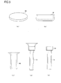
- a circular disk-shaped metal material MB which is made of a predetermined iron-based material is prepared, and deep drawing processing is performed to the metal material MB to obtain a cylindrical housing intermediate product which is to become the housing 2.
- the metal material MB is supplied to a transfer press (not shown) in which a plurality of rod-shaped punches (not shown), which have different outer diameters getting smaller in a gradual fashion, and a plurality of bottomed cylindrical dies (not shown), which have different hole diameters corresponding to the outer diameters of the punches, are mounted to be aligned with each other.
- the metal material MB is pressed in a plurality of stages by using the punches and the dies, whereby the metal material MB is formed into a cylindrical shape and the depth of the cylindrical shape is gradually increased as shown in Figs. 5(d) to (d) . Then, finally, both end portions of the metal material MB are cut to thereby obtain a cylindrical housing intermediate product 31 with a generally uniform thickness as a whole as shown in Fig. 5(e) .
- the housing intermediate product 31 has an engagement-portion corresponding portion 32 at one end thereof.
- the engagement-portion corresponding portion 32 has a relatively large diameter that corresponds to the tool engagement portion 6.
- a die D1 which has on an inner circumference thereof an outer circumference forming portion OM which has a shape corresponding to an outer circumferential shape of the tool engagement portion 6 and a vertically moveable punch P1
- the tool engagement portion 6 is formed.
- the housing intermediate product 31 is disposed in an inner circumference of the die D1.
- the punch P1 is lowered, so that the engagement-portion corresponding portion 32 is pushed into the outer circumference forming portion OM in the die D1 by the punch P1.
- both an outer circumference and inner circumference of the engagement-portion corresponding portion 32 are formed into a hexagonal shape in section, whereby a tool engagement portion 6 is formed as shown in Fig. 7(b) .
- an outer circumference at a front end side of the housing intermediate product 31 is pressed so as to deform a portion thereof which corresponds to the front-end-side body portion 9, whereby the holding portion 20 is formed.
- a screw portion 5 is formed at a predetermined portion of the housing intermediate product 31 through rolling. Further, a front end portion of the housing intermediate product 31 is pressed to be deformed in a curved fashion to thereby form a pressure contact portion 7, whereby a housing 2 is obtained.
- the heater member 3 is press fitted into the holding portion 20 of the housing 2, and the insulating bush 18 and the seal member 19 are disposed on an outer circumference of a rear end portion of the center pole 11. Then, the terminal pin 17 is crimped and fixed to the rear end portion of the center pole 11, whereby the glow plug 1 is obtained.
- the inner circumference of the tool engagement portion 6 has the shape which follows the outer circumferential shape of the tool engagement portion 6. Consequently, it is possible to prevent a risk of the thickness of the tool engagement portion 6 being increased locally, thereby making it possible to realize a reduction in weight of the tool engagement portion 6 and hence of the housing 2. As a result, it is possible to realize an improvement in fuel economy of the vehicle and a reduction in manufacturing cost of the glow plug.
- the thickness of the tool engagement portion 6 is 1.5 mm or smaller, whereby the thickness of the tool engagement portion 6 can be reduced sufficiently. Consequently, the weight of the housing 2 can be reduced further, whereby it is possible to realize more effectively the improvement in fuel economy of the vehicle and the reduction in manufacturing cost of the glow plug.
- the thickness of the tool engagement portion 6 is made uniform and the whole region of the tool engagement portion 6 is formed thin. Consequently, the weight of the housing 2 can be reduced further, and the working effect of improving the fuel economy or the like can be exhibited more effectively.
- the area of the projected region AR2 of the step portion 16 is 30% or larger of the area of the region AR1 which is surrounded by the projected line VL of the outer circumferential surface of the tool engagement portion 6. Consequently, the contact area of the seal member 19 with the step portion 16 can be increased largely. As a result, the extremely good gastightness can be realized in the interior of the housing 2.
- the housing 2 is formed thin as a whole, the weight of the housing 2 can be reduced further. As a result, it is possible to realize the improvement in fuel economy of the vehicle and the reduction in manufacturing cost of the glow plug more effectively.
- the holding portion 20 has the smallest outer diameter in the front-end-side body portion 9. Consequently, when an axial force is applied to the front-end-side body portion 9 in association with the mounting of the glow plug 1 in the internal combustion engine, the axial force is decomposed towards the heater member 3. Because of this, even if the housing 2 (the front-end-side body portion 9) is formed thin as in this embodiment, it is possible to prevent the reduction in holding force with which the heater member 3 is held by the holding portion 20 in a more ensured fashion.
Landscapes
- Engineering & Computer Science (AREA)
- Mechanical Engineering (AREA)
- Chemical & Material Sciences (AREA)
- Combustion & Propulsion (AREA)
- General Engineering & Computer Science (AREA)
- Resistance Heating (AREA)
Applications Claiming Priority (2)
| Application Number | Priority Date | Filing Date | Title |
|---|---|---|---|
| JP2012075293A JP5965180B2 (ja) | 2012-03-29 | 2012-03-29 | グロープラグ及びその製造方法 |
| PCT/JP2013/001391 WO2013145571A1 (fr) | 2012-03-29 | 2013-03-06 | Bougie à incandescence et son procédé de fabrication |
Publications (2)
| Publication Number | Publication Date |
|---|---|
| EP2833070A1 true EP2833070A1 (fr) | 2015-02-04 |
| EP2833070A4 EP2833070A4 (fr) | 2016-01-20 |
Family
ID=49258892
Family Applications (1)
| Application Number | Title | Priority Date | Filing Date |
|---|---|---|---|
| EP13768466.8A Withdrawn EP2833070A4 (fr) | 2012-03-29 | 2013-03-06 | Bougie à incandescence et son procédé de fabrication |
Country Status (6)
| Country | Link |
|---|---|
| US (1) | US9335047B2 (fr) |
| EP (1) | EP2833070A4 (fr) |
| JP (1) | JP5965180B2 (fr) |
| KR (1) | KR20140129334A (fr) |
| IN (1) | IN2014DN07943A (fr) |
| WO (1) | WO2013145571A1 (fr) |
Families Citing this family (1)
| Publication number | Priority date | Publication date | Assignee | Title |
|---|---|---|---|---|
| JP6738995B2 (ja) * | 2016-05-16 | 2020-08-12 | パナソニックIpマネジメント株式会社 | シャッターユニットおよび撮像装置 |
Family Cites Families (10)
| Publication number | Priority date | Publication date | Assignee | Title |
|---|---|---|---|---|
| JPS58182033A (ja) * | 1982-04-17 | 1983-10-24 | Ngk Spark Plug Co Ltd | グロ−プラグの中軸固着法 |
| CZ290040B6 (cs) * | 1994-11-10 | 2002-05-15 | J. Eberspächer Gmbh & Co. | Odpařovací hořák se spalovací komorou |
| DE19529994C2 (de) | 1994-11-10 | 2003-06-26 | Eberspaecher J Gmbh & Co | Verdampferbrenner für ein Heizgerät |
| IT1285043B1 (it) * | 1996-03-29 | 1998-06-03 | Cooper Ind Italia | Candela riscaldante ad incandescenza, particolarmente per motori a ciclo diesel |
| JP2000215963A (ja) * | 1999-01-25 | 2000-08-04 | Ngk Spark Plug Co Ltd | スパ―クプラグの製造設備及びスパ―クプラグの製造方法 |
| JP4300663B2 (ja) | 1999-12-24 | 2009-07-22 | 株式会社デンソー | 燃焼圧センサ構造体 |
| JP3589206B2 (ja) * | 2000-10-17 | 2004-11-17 | 株式会社ボッシュオートモーティブシステム | セラミックスヒータ型グロープラグおよびその製造方法。 |
| DE102006014215A1 (de) * | 2006-03-26 | 2007-09-27 | IFUTEC Ingenieurbüro für Umformtechnik GmbH | Verfahren zur Herstellung eines Hohlformteils |
| JP5335489B2 (ja) | 2009-03-06 | 2013-11-06 | 日本特殊陶業株式会社 | グロープラグ用の主体金具の製造方法 |
| JP5558021B2 (ja) * | 2009-04-13 | 2014-07-23 | ボッシュ株式会社 | ディーゼルエンジン用のメタルグロープラグのシース製造方法及びメタルグロープラグの製造方法、並びに、ディーゼルエンジン用のメタルグロープラグのシース及びディーゼルエンジン用のメタルグロープラグ |
-
2012
- 2012-03-29 JP JP2012075293A patent/JP5965180B2/ja not_active Expired - Fee Related
-
2013
- 2013-03-06 WO PCT/JP2013/001391 patent/WO2013145571A1/fr not_active Ceased
- 2013-03-06 KR KR20147027316A patent/KR20140129334A/ko not_active Ceased
- 2013-03-06 IN IN7943DEN2014 patent/IN2014DN07943A/en unknown
- 2013-03-06 US US14/388,067 patent/US9335047B2/en not_active Expired - Fee Related
- 2013-03-06 EP EP13768466.8A patent/EP2833070A4/fr not_active Withdrawn
Also Published As
| Publication number | Publication date |
|---|---|
| JP2013204945A (ja) | 2013-10-07 |
| WO2013145571A1 (fr) | 2013-10-03 |
| EP2833070A4 (fr) | 2016-01-20 |
| IN2014DN07943A (fr) | 2015-05-01 |
| JP5965180B2 (ja) | 2016-08-03 |
| KR20140129334A (ko) | 2014-11-06 |
| US9335047B2 (en) | 2016-05-10 |
| US20150300642A1 (en) | 2015-10-22 |
Similar Documents
| Publication | Publication Date | Title |
|---|---|---|
| US9644842B2 (en) | Glow plug and manufacturing method thereof | |
| EP2716975B1 (fr) | Bougie de préchauffage et procédé pour fabriquer une bougie de préchauffage | |
| JP2019158350A (ja) | ガスセンサ | |
| US20150075473A1 (en) | Glow plug and method for manufacturing same | |
| US9284938B2 (en) | Glow plug and fabrication method for same | |
| JP4220218B2 (ja) | スパークプラグ用中心電極の製造方法 | |
| US9335047B2 (en) | Glow plug and method for manufacturing same | |
| US9599341B2 (en) | Glow plug and method for manufacturing same | |
| GB2110572A (en) | Method for producing a composite center electrode and an electrode | |
| GB2169527A (en) | Method for producing an electrode for spark plug | |
| JP3471410B2 (ja) | スパークプラグ用主体金具の製造方法 | |
| JP2013228183A (ja) | グロープラグ | |
| JP5421042B2 (ja) | グロープラグの製造方法 | |
| JP2006125776A (ja) | グロープラグ | |
| JP2009074708A (ja) | グロープラグの製造方法 | |
| JP2006284084A (ja) | グロープラグの製造方法 |
Legal Events
| Date | Code | Title | Description |
|---|---|---|---|
| PUAI | Public reference made under article 153(3) epc to a published international application that has entered the european phase |
Free format text: ORIGINAL CODE: 0009012 |
|
| 17P | Request for examination filed |
Effective date: 20140929 |
|
| AK | Designated contracting states |
Kind code of ref document: A1 Designated state(s): AL AT BE BG CH CY CZ DE DK EE ES FI FR GB GR HR HU IE IS IT LI LT LU LV MC MK MT NL NO PL PT RO RS SE SI SK SM TR |
|
| AX | Request for extension of the european patent |
Extension state: BA ME |
|
| DAX | Request for extension of the european patent (deleted) | ||
| RA4 | Supplementary search report drawn up and despatched (corrected) |
Effective date: 20151217 |
|
| RIC1 | Information provided on ipc code assigned before grant |
Ipc: B21D 22/20 20060101ALI20151211BHEP Ipc: F23Q 7/00 20060101AFI20151211BHEP |
|
| STAA | Information on the status of an ep patent application or granted ep patent |
Free format text: STATUS: THE APPLICATION HAS BEEN WITHDRAWN |
|
| 18W | Application withdrawn |
Effective date: 20170503 |