EP2833181B1 - Cadre de distribution en fibre de verre doté de cassettes Patch - Google Patents
Cadre de distribution en fibre de verre doté de cassettes Patch Download PDFInfo
- Publication number
- EP2833181B1 EP2833181B1 EP14002112.2A EP14002112A EP2833181B1 EP 2833181 B1 EP2833181 B1 EP 2833181B1 EP 14002112 A EP14002112 A EP 14002112A EP 2833181 B1 EP2833181 B1 EP 2833181B1
- Authority
- EP
- European Patent Office
- Prior art keywords
- patch
- optical fibre
- distribution frame
- cassettes
- fibre distribution
- Prior art date
- Legal status (The legal status is an assumption and is not a legal conclusion. Google has not performed a legal analysis and makes no representation as to the accuracy of the status listed.)
- Active
Links
Images







Classifications
-
- G—PHYSICS
- G02—OPTICS
- G02B—OPTICAL ELEMENTS, SYSTEMS OR APPARATUS
- G02B6/00—Light guides; Structural details of arrangements comprising light guides and other optical elements, e.g. couplings
- G02B6/44—Mechanical structures for providing tensile strength and external protection for fibres, e.g. optical transmission cables
- G02B6/4439—Auxiliary devices
- G02B6/444—Systems or boxes with surplus lengths
- G02B6/4453—Cassettes
-
- G—PHYSICS
- G02—OPTICS
- G02B—OPTICAL ELEMENTS, SYSTEMS OR APPARATUS
- G02B6/00—Light guides; Structural details of arrangements comprising light guides and other optical elements, e.g. couplings
- G02B6/44—Mechanical structures for providing tensile strength and external protection for fibres, e.g. optical transmission cables
- G02B6/4439—Auxiliary devices
- G02B6/444—Systems or boxes with surplus lengths
- G02B6/4452—Distribution frames
- G02B6/44526—Panels or rackmounts covering a whole width of the frame or rack
-
- G—PHYSICS
- G02—OPTICS
- G02B—OPTICAL ELEMENTS, SYSTEMS OR APPARATUS
- G02B6/00—Light guides; Structural details of arrangements comprising light guides and other optical elements, e.g. couplings
- G02B6/44—Mechanical structures for providing tensile strength and external protection for fibres, e.g. optical transmission cables
- G02B6/4439—Auxiliary devices
- G02B6/444—Systems or boxes with surplus lengths
- G02B6/44528—Patch-cords; Connector arrangements in the system or in the box
Definitions
- the invention relates to an optical distributor, in particular a glass fiber distribution frame with a plurality of superposed compartments, each having a plurality of patch cassettes for patch cords or pig tails, each compartment having a drawer-like extendable shell or plate, in or on the patch cassettes are fastened at such a distance from each other that they are foldable on both sides to an end position in which they are arranged at an angle to the bottom of the shell.
- Such fiberglass distribution frames are from WP-A1-2009 / 106874 and the EP-A2-1111422 known.
- Optical manifolds of the type considered contain a frame or similar receptacle in which patch trays or patch panels are stacked.
- the height of such an optical distribution frame is limited, so only a certain maximum number of patch bins can be stacked on top of each other.
- the term "patch cable" is intended to include pig tails throughout.
- each compartment nzw a drawer-like extendable shell.
- Plate has, in or on the patch cassettes parallel to each other each attached to an edge portion so at the bottom of the shell or plate that they are pivotable or foldable about this edge portion.
- the trays (plates) have a rectangular, elongated shape and are extendable from their subjects perpendicular to their longitudinal axis.
- the patch cassettes are mounted transversely to the longitudinal axis of the shells at such a distance from each other that they are foldable on both sides to an end position in which they are arranged at an angle to the bottom of the shell, preferably between 30 and 45 ° lies.
- the cassettes can rest in their final position on a stop.
- the invention provides that the patch cassettes have coupling elements for optical connectors of the patch cords on both sides thereof. Since the patch cassettes are pivotally mounted on both sides, the respective required couplings or adapters for the connectors are easily accessible by the adjacent cassette or cassettes are simply folded away. Each side of the patch cassettes preferably contains six coupling elements or slots of the patch cords arranged one above the other.
- the lower edge of the patch cassettes forms the pivot axis.
- the patch cassettes may be provided at its lower edge with recesses which receive at the bottom of the shell mounted bearing body to which the cassettes may be attached.
- the cassettes are pivotable about the bearing bodies, which may have a round disc shape.
- the patch cassettes can also be mounted in another way pivotally in or on the shell or plate.
- patch cables run from a cassette through an adjacent to the cassette stack channel of the shell to a selected other cassette.
- a common input or output for all associated patch cables is provided at both lateral edges of the cassettes near the pivot axis, ie in the lower edge region of the cassettes.
- an arcuate guide element for the patch cord is attached to the input / output, which limits the bending radius, and under the guide member, the peripheral wall is left away, which can surround the cassettes in the overlying areas.
- the patch cables are moved only to a very small extent when connectors are created or changed. This eliminates the risk of damage to the patch cords as they are handled around the cassettes.
- each shell is connected via a telescopic linkage with its compartment, wherein the telescopic linkage is formed so that the shells can be completely pulled out of the subjects out.
- Each compartment has expediently a fixed lid and in the side walls each have an outgoing from the edge slot which opens into an inlet / outlet opening for the patch cord.
- a curved, also provided with a slot guide element for the fiber optic or patch cables can be attached.
- a hinged flap may be attached, which should hang down freely when working on the connectors and which can close after the insertion of the shell in the associated compartment whose front, in the upright position locks.
- the patch cassettes are each provided with a lateral extension, which has a receiving device for an overlong part of patch cables or pig tails.
- This lateral extension is preferably provided on the side of the patch cassettes which lies in the associated compartment inside.
- the lateral extension on the other, outside lying side of the patch cartridge may be formed.
- each patch cassette is provided on both sides with an extension with an associated receiving device for the excess length of patch cables.
- the lateral extension is expediently formed in one piece with the rest of the patch cassette.
- the receiving device advantageously includes on both sides of the plate of the patch cassette projecting round, for example, circular or oval ring of webs, around which the overlong part of the patch cord is wound.
- round for example, circular or oval ring of webs
- a round for example, circular or oval hole may be formed in the lateral extension, which is enclosed on both sides of the patch cassette of protruding webs.
- the webs may have outwardly angled upper end portions, so that the patch cords are securely held in the wound state on the receiving device.
- each tray or drawer-like extendable plate is provided with eight swiveling or folding patch cassettes.
- the distribution frame contains as many patch locations as the associated distribution frame for the splice trays.
- the invention thus provides an optical distributor with a frame with superposed patch compartments with extendable shells and patch cassettes foldable therein, which has a high packing density and allows good operability with gentle handling of the patch cords.
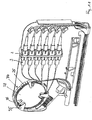
- patch cassette 1 contains on both sides six superimposed couplings 2 for optical connector 3 of patch cables 4, which are guided via guide elements 5 to both inputs / outputs 6.
- guide elements 5 In front of the inputs / outputs 6, a further guide element 7 is attached, which limits the bending radius of the patch cord 4 so that the glass fibers can not be damaged here.
- the patch cassettes 1 have at their lower edge recesses 8, enter the attached to the bottom 9 of an associated shell 10 bearing body 11.
- the patch cassettes 1 are attached to the bearing bodies 11 so as to be foldable in both lateral directions to allow either the front or the front side Rear of a patch cartridge for making or changing connectors exposed.
- FIG. 1 shows, the patch cords 4 of the right half are guided through a channel 12 to the inside of the patch cassette 1.
- each patch cassette 1 includes a protruding peripheral wall 13 which is left out at the inputs / outputs 6.
- the patch cassette 1 b on the left side is folded to the left, so that it becomes apparent that the back side of the patch cassettes 1 are provided with the same elements as their front side.
- the patch cassette 1 b is applied to stops, not shown.
- each compartment 14 includes a bottom wall 16, a rear wall 17, side walls 18 and a top wall, which is omitted in the figures, however. It is understood that in an optical distribution frame a plurality of such compartments 14 are stacked one above the other.
- FIG. 5 the telescopic linkage 15 is only partially shown, but it is visible that the shell 10 is completely withdrawn from the tray 14.
- the patch cords 1 are led through the lateral recesses above the side walls 18 to the inlet-outlet openings 20 and their funnels 21, before the shell 10 is pushed back into the compartment 14 after the connections have been made.
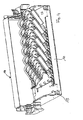
- FIGS. 7 to 10 show a second embodiment of the invention, wherein the parts which correspond to those of the first embodiment are identified by the same reference numerals.
- the patch cassettes 1A each have a receiving device or take-up device 22, to which a section 23 of patch cables 4 can be wound up when the associated patch cables have an excess length.
- the patch cassettes 1A on the side facing the interior of the associated compartment have a lateral extension 24, which in the illustrated embodiment is formed integrally with the patch cassette 1A.
- the patch cassettes on both sides or - in the representation of Figure 7a - Only on the right side can have an extension with a winding device.
- the winding device 22 may also be formed on a separate, preferably plate-shaped component, which may be fastened to the patch cassette, for example latched thereto.
- the take-up device 22 includes on both sides of the patch cassette 1A an oval rim of vertically protruding from the plate of the patch cassette webs 25 whose upper ends are angled outwards (reference 26), so that the wound portions 23 of the excess lengths of the patch cables safely are held on the Aufwickelaufraum 22.
- the webs 25 may be interrupted (reference numeral 27) so that patch cords can be passed through the wreath on their way to their slots, such as FIG. 7b shows.
- the take-up device 22 is not used because the patch cables of the left side have no excess length.
- the interior of the ring formed from the webs 25 may be a hole or an oval window 28 in the patch cassette 1A.
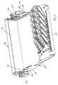
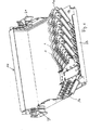
- FIGS. 8 to 10 show that each drawer-like member, which is referred to as shell 10 in the first embodiment, is formed in the second embodiment substantially by a base plate 10a on which, in this embodiment, eight patch cassettes 1A are pivotally mounted side by side in parallel.
- each "drawer" contains as many patch locations as splice places are usually provided in a splice distribution frame.
- a compartment 14 a is shown with its closed upper wall 29.
- the "drawer” 10a is in turn attached at its two end portions to associated telescopic rods 15 and pulled out of the compartment 14a.
- a flap 32 is pivotally mounted, with the compartment 14a is closed with inserted "drawer" 10a.
- the flap 32 is provided with a snap closure 33.
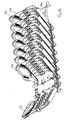
- the Figures 11 and 12 show a particularly preferred variant of the second embodiment, in which the excess lengths of the patch cord (or pig tails) are not wound around the outside of the rim of webs 25, but are stored in the limited by the webs 25 interior.
- the cable sections are here optionally in the wound state on the inner walls of the webs 25 and are covered by angled wall portions 35 and thus securely held in the ring 25 of webs.
- a hole or an oval window 28 may be formed to save material.
- the cables 4 can then rest, for example, on the angled wall sections 35 arranged on both sides. It can also be provided that not the entire interior of the ring of webs 25, but only a smaller central area is cut away.
Landscapes
- Physics & Mathematics (AREA)
- General Physics & Mathematics (AREA)
- Optics & Photonics (AREA)
- Light Guides In General And Applications Therefor (AREA)
Claims (13)
- Cadre de distribution en fibres de verre comprenant plusieurs compartiments disposés les uns au-dessus des autres, qui présentent respectivement plusieurs cassettes Patch pour des câbles Patch ou des paires torsadées, dans lequel chaque compartiment (14, 14a) présente une coque ou une plaque (10, 10a) pouvant être déployée à la manière d'un tiroir, dans laquelle ou sur laquelle les cassettes Patch (1, 1A) sont fixées les unes par rapport aux autres à une distance telle qu'elles peuvent être rabattues en direction des deux côtés jusque dans une position finale, dans laquelle elles sont disposées selon un angle donné par rapport au fond (9) de la coque (10, 10a),
caractérisé en ce
que les cassettes Patch (1, 1A) ont, au niveau de leurs deux côtés, des éléments de couplage (2) pour des connecteurs (3) optiques des câbles Patch (4) ou des paires torsadées. - Cadre de distribution en fibres de verre selon la revendication 1,
caractérisé en ce
que sont présents, au niveau de chaque côté des cassettes Patch (1, 1A), six éléments de couplage (2). - Cadre de distribution en fibres de verre selon les revendications 1 à 2,
caractérisé en ce
que le bord (22) inférieur des cassettes Patch (1, 1A) forme l'axe de pivotement. - Cadre de distribution en fibres de verre selon l'une quelconque des revendications 1 à 3,
caractérisé en ce
que les cassettes Patch (1, 1A) ont, au niveau des deux bords latéraux, à proximité de l'axe de pivotement (22), une entrée/sortie (6) commune pour tous les câbles Patch (4) ou paires torsadées associés. - Cadre de distribution en fibres de verre selon la revendication 4,
caractérisé en ce
qu'un élément de guidage (7) pour les câbles Patch (4) ou les paires torsadées est installé au niveau de l'entrée/la sortie (6). - Cadre de distribution en fibres de verre selon les revendications 1 à 5,
caractérisé en ce
que chaque coque ou plaque (10, 10a) est reliée à son compartiment (14, 14a) par l'intermédiaire d'une tringle télescopique (15). - Cadre de distribution en fibres de verre selon les revendications 1 à 6,
caractérisé en ce
que chaque compartiment (14, 14a) présente un couvercle fixe et, dans les parois latérales (18), respectivement un évidement en forme de fente, qui débouche dans une ouverture murale (20) pourvue d'un élément de guidage (21) servant à faire entrer/sortir des câbles Patch (4) ou des paires torsadées. - Cadre de distribution en fibres de verre selon les revendications 1 à 7,
caractérisé en ce
qu'est fixé, au niveau du bord avant (23) de la coque (10), un clapet pouvant pivoter, qui peut dégager ou fermer le côté avant du compartiment (14). - Cadre de distribution en fibres de verre selon les revendications 1 à 8,
caractérisé en ce
que les cassettes Patch (1A) présentent respectivement au moins un prolongement (24) latéral pourvu d'un dispositif de réception (22) pour une partie (23) rallongée de câbles Patch (4) ou de paires torsadées. - Cadre de distribution en fibres de verre selon la revendication 9,
caractérisé en ce
que le dispositif de réception (22) présente une couronne ronde, de préférence ovale, faisant saillie des deux côtés, composée d'entretoises (25), autour de laquelle la partie rallongée des câbles Patch (4) ou des paires torsadées peut être enroulée. - Cadre de distribution en fibres de verre selon la revendication 9,
caractérisé en ce
que le dispositif de réception (22) présente une couronne ronde, de préférence ovale, faisant saillie des deux côtés, composée d'entretoises (25), dans l'espace intérieur de laquelle la partie rallongée des câbles peut être placée. - Cadre de distribution en fibres de verre selon les revendications 9 à 11,
caractérisé en ce
que la cassette Patch (1A) présente, dans le prolongement latéral, un trou rond circulaire ou ovale, qui est entouré des deux côtés des cassettes Patch par des entretoises (25) dépassant. - Cadre de distribution en fibres de verre selon les revendications 9 à 12,
caractérisé en ce
que chaque coque ou plaque (10a) pouvant être déployée présente huit cassettes Patch (1A).
Applications Claiming Priority (1)
| Application Number | Priority Date | Filing Date | Title |
|---|---|---|---|
| DE102013012975.3A DE102013012975B4 (de) | 2013-08-03 | 2013-08-03 | Glasfaser-Verteilungsrahmen mit Patch-Kassetten |
Publications (2)
| Publication Number | Publication Date |
|---|---|
| EP2833181A1 EP2833181A1 (fr) | 2015-02-04 |
| EP2833181B1 true EP2833181B1 (fr) | 2016-07-27 |
Family
ID=51059234
Family Applications (1)
| Application Number | Title | Priority Date | Filing Date |
|---|---|---|---|
| EP14002112.2A Active EP2833181B1 (fr) | 2013-08-03 | 2014-06-18 | Cadre de distribution en fibre de verre doté de cassettes Patch |
Country Status (2)
| Country | Link |
|---|---|
| EP (1) | EP2833181B1 (fr) |
| DE (1) | DE102013012975B4 (fr) |
Families Citing this family (2)
| Publication number | Priority date | Publication date | Assignee | Title |
|---|---|---|---|---|
| DE102015006829B3 (de) * | 2015-06-02 | 2016-08-25 | Langmatz Gmbh | Glasfaser-Verteilungsrahmen |
| CN118465947B (zh) * | 2024-07-15 | 2024-09-06 | 杭州通昱光网科技有限公司 | 一种组合式调节型光纤配线架 |
Family Cites Families (10)
| Publication number | Priority date | Publication date | Assignee | Title |
|---|---|---|---|---|
| US4373776A (en) * | 1980-06-30 | 1983-02-15 | Northern Telecom Limited | Protection case for optical fiber splices |
| FR2710419B1 (fr) * | 1993-09-24 | 1995-12-15 | Blanchard Anne Marie | Dispositif de raccordement pour fibres optiques. |
| US5402515A (en) * | 1994-03-01 | 1995-03-28 | Minnesota Mining And Manufacturing Company | Fiber distribution frame system, cabinets, trays and fiber optic connector couplings |
| GB9408292D0 (en) * | 1994-04-26 | 1994-06-15 | Raychem Sa Nv | Optical fibre protector |
| US6009224A (en) * | 1997-11-06 | 1999-12-28 | Allen; Barry Wayne | Fiber optic organizer with lockable trays and method of accessing a tray |
| GB9801198D0 (en) * | 1998-01-21 | 1998-03-18 | Raychem Sa Nv | Optical fibre assembly |
| GB9928201D0 (en) * | 1999-11-30 | 2000-01-26 | Raychem Sa Nv | Optical fibre connection unit |
| DE20200065U1 (de) * | 2002-01-03 | 2003-03-06 | CCS Technology, Inc., Wilmington, Del. | Spleißkassettenmanagementsystem |
| GB0803802D0 (en) * | 2008-02-29 | 2008-04-09 | Tyco Electronics Raychem Nv | Optical fibre organiser |
| JP5856449B2 (ja) * | 2011-11-25 | 2016-02-09 | 日本電信電話株式会社 | 光ケーブル接続用クロージャ |
-
2013
- 2013-08-03 DE DE102013012975.3A patent/DE102013012975B4/de not_active Expired - Fee Related
-
2014
- 2014-06-18 EP EP14002112.2A patent/EP2833181B1/fr active Active
Also Published As
| Publication number | Publication date |
|---|---|
| DE102013012975A1 (de) | 2015-02-05 |
| DE102013012975B4 (de) | 2019-03-28 |
| EP2833181A1 (fr) | 2015-02-04 |
Similar Documents
| Publication | Publication Date | Title |
|---|---|---|
| DE69217812T2 (de) | Verteilergestell für optische Kabel hoher Kapazität | |
| EP1891474B1 (fr) | Dispositif de distribution de fibres optiques | |
| DE69433613T2 (de) | Verteiler für optische Fibern | |
| DE69124902T2 (de) | Kassette für optische Verbindungen | |
| DE69608314T2 (de) | Spleissanordnungen für faseroptische kabel | |
| DE3841607C2 (de) | Kassette für Überlängen von Lichtwellenleitern im Spleißstellenbereich | |
| EP3511753B1 (fr) | Module d'épissure à libération de câble | |
| DE69930212T2 (de) | Faseroptischer Zusammenschaltungsabschluss mit einem Fasermanagementrahmen | |
| EP2005232B1 (fr) | Separateur pour fibres optiques | |
| EP0369524A2 (fr) | Rack de distribution pour l'établissement des connections optiques à option libre | |
| DE19611770A1 (de) | Managementfähige Spleißkassette | |
| DE60123059T2 (de) | In gebäuden anzuwendendes gehäuse zur verbindung zwischen optischen fasern und arbeitsplätzen | |
| EP2690474A2 (fr) | Dispositif pour le stockage et la manipulation de guides d'ondes | |
| EP2409192B1 (fr) | Panneau de connexion pour un répartiteur optique | |
| DE102016008729B4 (de) | Glasfaser-Abschlusspunkt mit einer Kassette | |
| EP0579019A1 (fr) | Dispositif pour deposer cassettes d'épissure pour guides d'ondes optiques dans un manchon à câble | |
| DE102013012975B4 (de) | Glasfaser-Verteilungsrahmen mit Patch-Kassetten | |
| DE102012206743A1 (de) | Lichtwellenleiter-Verteilerschrank | |
| AT392850B (de) | Muffe fuer lichtwellenleiter | |
| DE102020114225B3 (de) | Faserführungsmodul sowie Organizersystem | |
| DE3540473C2 (fr) | ||
| DE102020114226B4 (de) | Faserführungsmodul sowie Organizersystem | |
| DE102019132667B3 (de) | Kassette mit einem pWDM-Filter | |
| DE102018109668B4 (de) | Kassette zur Aufnahme von Lichtwellenleitern sowie System zur Verbindung von wenigstens zwei Lichtwellenleitern | |
| DE202024101279U1 (de) | Anschlussbox für Glasfasern mit Überlängenablage |
Legal Events
| Date | Code | Title | Description |
|---|---|---|---|
| 17P | Request for examination filed |
Effective date: 20140618 |
|
| AK | Designated contracting states |
Kind code of ref document: A1 Designated state(s): AL AT BE BG CH CY CZ DE DK EE ES FI FR GB GR HR HU IE IS IT LI LT LU LV MC MK MT NL NO PL PT RO RS SE SI SK SM TR |
|
| AX | Request for extension of the european patent |
Extension state: BA ME |
|
| PUAI | Public reference made under article 153(3) epc to a published international application that has entered the european phase |
Free format text: ORIGINAL CODE: 0009012 |
|
| R17P | Request for examination filed (corrected) |
Effective date: 20150304 |
|
| RBV | Designated contracting states (corrected) |
Designated state(s): AL AT BE BG CH CY CZ DE DK EE ES FI FR GB GR HR HU IE IS IT LI LT LU LV MC MK MT NL NO PL PT RO RS SE SI SK SM TR |
|
| GRAP | Despatch of communication of intention to grant a patent |
Free format text: ORIGINAL CODE: EPIDOSNIGR1 |
|
| INTG | Intention to grant announced |
Effective date: 20160421 |
|
| GRAS | Grant fee paid |
Free format text: ORIGINAL CODE: EPIDOSNIGR3 |
|
| GRAA | (expected) grant |
Free format text: ORIGINAL CODE: 0009210 |
|
| AK | Designated contracting states |
Kind code of ref document: B1 Designated state(s): AL AT BE BG CH CY CZ DE DK EE ES FI FR GB GR HR HU IE IS IT LI LT LU LV MC MK MT NL NO PL PT RO RS SE SI SK SM TR |
|
| REG | Reference to a national code |
Ref country code: GB Ref legal event code: FG4D Free format text: NOT ENGLISH |
|
| REG | Reference to a national code |
Ref country code: CH Ref legal event code: EP |
|
| REG | Reference to a national code |
Ref country code: AT Ref legal event code: REF Ref document number: 816249 Country of ref document: AT Kind code of ref document: T Effective date: 20160815 |
|
| REG | Reference to a national code |
Ref country code: IE Ref legal event code: FG4D Free format text: LANGUAGE OF EP DOCUMENT: GERMAN |
|
| REG | Reference to a national code |
Ref country code: DE Ref legal event code: R096 Ref document number: 502014001161 Country of ref document: DE |
|
| REG | Reference to a national code |
Ref country code: LT Ref legal event code: MG4D |
|
| REG | Reference to a national code |
Ref country code: NL Ref legal event code: MP Effective date: 20160727 |
|
| PG25 | Lapsed in a contracting state [announced via postgrant information from national office to epo] |
Ref country code: IT Free format text: LAPSE BECAUSE OF FAILURE TO SUBMIT A TRANSLATION OF THE DESCRIPTION OR TO PAY THE FEE WITHIN THE PRESCRIBED TIME-LIMIT Effective date: 20160727 Ref country code: IS Free format text: LAPSE BECAUSE OF FAILURE TO SUBMIT A TRANSLATION OF THE DESCRIPTION OR TO PAY THE FEE WITHIN THE PRESCRIBED TIME-LIMIT Effective date: 20161127 Ref country code: RS Free format text: LAPSE BECAUSE OF FAILURE TO SUBMIT A TRANSLATION OF THE DESCRIPTION OR TO PAY THE FEE WITHIN THE PRESCRIBED TIME-LIMIT Effective date: 20160727 Ref country code: FI Free format text: LAPSE BECAUSE OF FAILURE TO SUBMIT A TRANSLATION OF THE DESCRIPTION OR TO PAY THE FEE WITHIN THE PRESCRIBED TIME-LIMIT Effective date: 20160727 Ref country code: HR Free format text: LAPSE BECAUSE OF FAILURE TO SUBMIT A TRANSLATION OF THE DESCRIPTION OR TO PAY THE FEE WITHIN THE PRESCRIBED TIME-LIMIT Effective date: 20160727 Ref country code: LT Free format text: LAPSE BECAUSE OF FAILURE TO SUBMIT A TRANSLATION OF THE DESCRIPTION OR TO PAY THE FEE WITHIN THE PRESCRIBED TIME-LIMIT Effective date: 20160727 Ref country code: NL Free format text: LAPSE BECAUSE OF FAILURE TO SUBMIT A TRANSLATION OF THE DESCRIPTION OR TO PAY THE FEE WITHIN THE PRESCRIBED TIME-LIMIT Effective date: 20160727 Ref country code: NO Free format text: LAPSE BECAUSE OF FAILURE TO SUBMIT A TRANSLATION OF THE DESCRIPTION OR TO PAY THE FEE WITHIN THE PRESCRIBED TIME-LIMIT Effective date: 20161027 |
|
| PG25 | Lapsed in a contracting state [announced via postgrant information from national office to epo] |
Ref country code: GR Free format text: LAPSE BECAUSE OF FAILURE TO SUBMIT A TRANSLATION OF THE DESCRIPTION OR TO PAY THE FEE WITHIN THE PRESCRIBED TIME-LIMIT Effective date: 20161028 Ref country code: ES Free format text: LAPSE BECAUSE OF FAILURE TO SUBMIT A TRANSLATION OF THE DESCRIPTION OR TO PAY THE FEE WITHIN THE PRESCRIBED TIME-LIMIT Effective date: 20160727 Ref country code: SE Free format text: LAPSE BECAUSE OF FAILURE TO SUBMIT A TRANSLATION OF THE DESCRIPTION OR TO PAY THE FEE WITHIN THE PRESCRIBED TIME-LIMIT Effective date: 20160727 Ref country code: LV Free format text: LAPSE BECAUSE OF FAILURE TO SUBMIT A TRANSLATION OF THE DESCRIPTION OR TO PAY THE FEE WITHIN THE PRESCRIBED TIME-LIMIT Effective date: 20160727 Ref country code: PL Free format text: LAPSE BECAUSE OF FAILURE TO SUBMIT A TRANSLATION OF THE DESCRIPTION OR TO PAY THE FEE WITHIN THE PRESCRIBED TIME-LIMIT Effective date: 20160727 Ref country code: PT Free format text: LAPSE BECAUSE OF FAILURE TO SUBMIT A TRANSLATION OF THE DESCRIPTION OR TO PAY THE FEE WITHIN THE PRESCRIBED TIME-LIMIT Effective date: 20161128 |
|
| PG25 | Lapsed in a contracting state [announced via postgrant information from national office to epo] |
Ref country code: RO Free format text: LAPSE BECAUSE OF FAILURE TO SUBMIT A TRANSLATION OF THE DESCRIPTION OR TO PAY THE FEE WITHIN THE PRESCRIBED TIME-LIMIT Effective date: 20160727 Ref country code: EE Free format text: LAPSE BECAUSE OF FAILURE TO SUBMIT A TRANSLATION OF THE DESCRIPTION OR TO PAY THE FEE WITHIN THE PRESCRIBED TIME-LIMIT Effective date: 20160727 |
|
| REG | Reference to a national code |
Ref country code: DE Ref legal event code: R097 Ref document number: 502014001161 Country of ref document: DE |
|
| PG25 | Lapsed in a contracting state [announced via postgrant information from national office to epo] |
Ref country code: BG Free format text: LAPSE BECAUSE OF FAILURE TO SUBMIT A TRANSLATION OF THE DESCRIPTION OR TO PAY THE FEE WITHIN THE PRESCRIBED TIME-LIMIT Effective date: 20161027 Ref country code: CZ Free format text: LAPSE BECAUSE OF FAILURE TO SUBMIT A TRANSLATION OF THE DESCRIPTION OR TO PAY THE FEE WITHIN THE PRESCRIBED TIME-LIMIT Effective date: 20160727 Ref country code: SM Free format text: LAPSE BECAUSE OF FAILURE TO SUBMIT A TRANSLATION OF THE DESCRIPTION OR TO PAY THE FEE WITHIN THE PRESCRIBED TIME-LIMIT Effective date: 20160727 Ref country code: SK Free format text: LAPSE BECAUSE OF FAILURE TO SUBMIT A TRANSLATION OF THE DESCRIPTION OR TO PAY THE FEE WITHIN THE PRESCRIBED TIME-LIMIT Effective date: 20160727 Ref country code: DK Free format text: LAPSE BECAUSE OF FAILURE TO SUBMIT A TRANSLATION OF THE DESCRIPTION OR TO PAY THE FEE WITHIN THE PRESCRIBED TIME-LIMIT Effective date: 20160727 |
|
| PLBE | No opposition filed within time limit |
Free format text: ORIGINAL CODE: 0009261 |
|
| STAA | Information on the status of an ep patent application or granted ep patent |
Free format text: STATUS: NO OPPOSITION FILED WITHIN TIME LIMIT |
|
| 26N | No opposition filed |
Effective date: 20170502 |
|
| PG25 | Lapsed in a contracting state [announced via postgrant information from national office to epo] |
Ref country code: SI Free format text: LAPSE BECAUSE OF FAILURE TO SUBMIT A TRANSLATION OF THE DESCRIPTION OR TO PAY THE FEE WITHIN THE PRESCRIBED TIME-LIMIT Effective date: 20160727 |
|
| PG25 | Lapsed in a contracting state [announced via postgrant information from national office to epo] |
Ref country code: MC Free format text: LAPSE BECAUSE OF FAILURE TO SUBMIT A TRANSLATION OF THE DESCRIPTION OR TO PAY THE FEE WITHIN THE PRESCRIBED TIME-LIMIT Effective date: 20160727 |
|
| REG | Reference to a national code |
Ref country code: CH Ref legal event code: PL |
|
| REG | Reference to a national code |
Ref country code: IE Ref legal event code: MM4A |
|
| REG | Reference to a national code |
Ref country code: FR Ref legal event code: ST Effective date: 20180228 |
|
| PG25 | Lapsed in a contracting state [announced via postgrant information from national office to epo] |
Ref country code: IE Free format text: LAPSE BECAUSE OF NON-PAYMENT OF DUE FEES Effective date: 20170618 Ref country code: LI Free format text: LAPSE BECAUSE OF NON-PAYMENT OF DUE FEES Effective date: 20170630 Ref country code: CH Free format text: LAPSE BECAUSE OF NON-PAYMENT OF DUE FEES Effective date: 20170630 Ref country code: LU Free format text: LAPSE BECAUSE OF NON-PAYMENT OF DUE FEES Effective date: 20170618 |
|
| PG25 | Lapsed in a contracting state [announced via postgrant information from national office to epo] |
Ref country code: FR Free format text: LAPSE BECAUSE OF NON-PAYMENT OF DUE FEES Effective date: 20170630 |
|
| REG | Reference to a national code |
Ref country code: BE Ref legal event code: MM Effective date: 20170630 |
|
| PG25 | Lapsed in a contracting state [announced via postgrant information from national office to epo] |
Ref country code: BE Free format text: LAPSE BECAUSE OF NON-PAYMENT OF DUE FEES Effective date: 20170630 |
|
| PG25 | Lapsed in a contracting state [announced via postgrant information from national office to epo] |
Ref country code: MT Free format text: LAPSE BECAUSE OF FAILURE TO SUBMIT A TRANSLATION OF THE DESCRIPTION OR TO PAY THE FEE WITHIN THE PRESCRIBED TIME-LIMIT Effective date: 20160727 |
|
| PG25 | Lapsed in a contracting state [announced via postgrant information from national office to epo] |
Ref country code: AL Free format text: LAPSE BECAUSE OF FAILURE TO SUBMIT A TRANSLATION OF THE DESCRIPTION OR TO PAY THE FEE WITHIN THE PRESCRIBED TIME-LIMIT Effective date: 20160727 |
|
| GBPC | Gb: european patent ceased through non-payment of renewal fee |
Effective date: 20180618 |
|
| PG25 | Lapsed in a contracting state [announced via postgrant information from national office to epo] |
Ref country code: GB Free format text: LAPSE BECAUSE OF NON-PAYMENT OF DUE FEES Effective date: 20180618 |
|
| PG25 | Lapsed in a contracting state [announced via postgrant information from national office to epo] |
Ref country code: HU Free format text: LAPSE BECAUSE OF FAILURE TO SUBMIT A TRANSLATION OF THE DESCRIPTION OR TO PAY THE FEE WITHIN THE PRESCRIBED TIME-LIMIT; INVALID AB INITIO Effective date: 20140618 |
|
| PG25 | Lapsed in a contracting state [announced via postgrant information from national office to epo] |
Ref country code: CY Free format text: LAPSE BECAUSE OF FAILURE TO SUBMIT A TRANSLATION OF THE DESCRIPTION OR TO PAY THE FEE WITHIN THE PRESCRIBED TIME-LIMIT Effective date: 20160727 |
|
| PG25 | Lapsed in a contracting state [announced via postgrant information from national office to epo] |
Ref country code: MK Free format text: LAPSE BECAUSE OF FAILURE TO SUBMIT A TRANSLATION OF THE DESCRIPTION OR TO PAY THE FEE WITHIN THE PRESCRIBED TIME-LIMIT Effective date: 20160727 |
|
| PG25 | Lapsed in a contracting state [announced via postgrant information from national office to epo] |
Ref country code: TR Free format text: LAPSE BECAUSE OF FAILURE TO SUBMIT A TRANSLATION OF THE DESCRIPTION OR TO PAY THE FEE WITHIN THE PRESCRIBED TIME-LIMIT Effective date: 20160727 |
|
| REG | Reference to a national code |
Ref country code: AT Ref legal event code: MM01 Ref document number: 816249 Country of ref document: AT Kind code of ref document: T Effective date: 20190618 |
|
| PG25 | Lapsed in a contracting state [announced via postgrant information from national office to epo] |
Ref country code: AT Free format text: LAPSE BECAUSE OF NON-PAYMENT OF DUE FEES Effective date: 20190618 |
|
| P01 | Opt-out of the competence of the unified patent court (upc) registered |
Effective date: 20230505 |
|
| PGFP | Annual fee paid to national office [announced via postgrant information from national office to epo] |
Ref country code: DE Payment date: 20250626 Year of fee payment: 12 |