EP2833193B1 - Anzeigevorrichtung für ein fahrzeug - Google Patents
Anzeigevorrichtung für ein fahrzeug Download PDFInfo
- Publication number
- EP2833193B1 EP2833193B1 EP13768673.9A EP13768673A EP2833193B1 EP 2833193 B1 EP2833193 B1 EP 2833193B1 EP 13768673 A EP13768673 A EP 13768673A EP 2833193 B1 EP2833193 B1 EP 2833193B1
- Authority
- EP
- European Patent Office
- Prior art keywords
- laser light
- temperature
- light source
- display device
- scanning
- Prior art date
- Legal status (The legal status is an assumption and is not a legal conclusion. Google has not performed a legal analysis and makes no representation as to the accuracy of the status listed.)
- Not-in-force
Links
Images




Classifications
-
- G—PHYSICS
- G02—OPTICS
- G02B—OPTICAL ELEMENTS, SYSTEMS OR APPARATUS
- G02B27/00—Optical systems or apparatus not provided for by any of the groups G02B1/00 - G02B26/00, G02B30/00
- G02B27/01—Head-up displays
- G02B27/0101—Head-up displays characterised by optical features
-
- G—PHYSICS
- G02—OPTICS
- G02B—OPTICAL ELEMENTS, SYSTEMS OR APPARATUS
- G02B26/00—Optical devices or arrangements for the control of light using movable or deformable optical elements
- G02B26/08—Optical devices or arrangements for the control of light using movable or deformable optical elements for controlling the direction of light
- G02B26/0816—Optical devices or arrangements for the control of light using movable or deformable optical elements for controlling the direction of light by means of one or more reflecting elements
- G02B26/0833—Optical devices or arrangements for the control of light using movable or deformable optical elements for controlling the direction of light by means of one or more reflecting elements the reflecting element being a micromechanical device, e.g. a MEMS mirror, DMD
-
- B—PERFORMING OPERATIONS; TRANSPORTING
- B60—VEHICLES IN GENERAL
- B60K—ARRANGEMENT OR MOUNTING OF PROPULSION UNITS OR OF TRANSMISSIONS IN VEHICLES; ARRANGEMENT OR MOUNTING OF PLURAL DIVERSE PRIME-MOVERS IN VEHICLES; AUXILIARY DRIVES FOR VEHICLES; INSTRUMENTATION OR DASHBOARDS FOR VEHICLES; ARRANGEMENTS IN CONNECTION WITH COOLING, AIR INTAKE, GAS EXHAUST OR FUEL SUPPLY OF PROPULSION UNITS IN VEHICLES
- B60K35/00—Instruments specially adapted for vehicles; Arrangement of instruments in or on vehicles
- B60K35/20—Output arrangements, i.e. from vehicle to user, associated with vehicle functions or specially adapted therefor
- B60K35/21—Output arrangements, i.e. from vehicle to user, associated with vehicle functions or specially adapted therefor using visual output, e.g. blinking lights or matrix displays
- B60K35/23—Head-up displays [HUD]
-
- B—PERFORMING OPERATIONS; TRANSPORTING
- B60—VEHICLES IN GENERAL
- B60K—ARRANGEMENT OR MOUNTING OF PROPULSION UNITS OR OF TRANSMISSIONS IN VEHICLES; ARRANGEMENT OR MOUNTING OF PLURAL DIVERSE PRIME-MOVERS IN VEHICLES; AUXILIARY DRIVES FOR VEHICLES; INSTRUMENTATION OR DASHBOARDS FOR VEHICLES; ARRANGEMENTS IN CONNECTION WITH COOLING, AIR INTAKE, GAS EXHAUST OR FUEL SUPPLY OF PROPULSION UNITS IN VEHICLES
- B60K35/00—Instruments specially adapted for vehicles; Arrangement of instruments in or on vehicles
- B60K35/60—Instruments characterised by their location or relative disposition in or on vehicles
-
- G—PHYSICS
- G02—OPTICS
- G02B—OPTICAL ELEMENTS, SYSTEMS OR APPARATUS
- G02B26/00—Optical devices or arrangements for the control of light using movable or deformable optical elements
- G02B26/08—Optical devices or arrangements for the control of light using movable or deformable optical elements for controlling the direction of light
- G02B26/10—Scanning systems
- G02B26/105—Scanning systems with one or more pivoting mirrors or galvano-mirrors
-
- G—PHYSICS
- G02—OPTICS
- G02B—OPTICAL ELEMENTS, SYSTEMS OR APPARATUS
- G02B27/00—Optical systems or apparatus not provided for by any of the groups G02B1/00 - G02B26/00, G02B30/00
- G02B27/01—Head-up displays
-
- G—PHYSICS
- G02—OPTICS
- G02B—OPTICAL ELEMENTS, SYSTEMS OR APPARATUS
- G02B27/00—Optical systems or apparatus not provided for by any of the groups G02B1/00 - G02B26/00, G02B30/00
- G02B27/01—Head-up displays
- G02B27/0149—Head-up displays characterised by mechanical features
-
- G—PHYSICS
- G02—OPTICS
- G02B—OPTICAL ELEMENTS, SYSTEMS OR APPARATUS
- G02B5/00—Optical elements other than lenses
- G02B5/30—Polarising elements
-
- G—PHYSICS
- G03—PHOTOGRAPHY; CINEMATOGRAPHY; ANALOGOUS TECHNIQUES USING WAVES OTHER THAN OPTICAL WAVES; ELECTROGRAPHY; HOLOGRAPHY
- G03B—APPARATUS OR ARRANGEMENTS FOR TAKING PHOTOGRAPHS OR FOR PROJECTING OR VIEWING THEM; APPARATUS OR ARRANGEMENTS EMPLOYING ANALOGOUS TECHNIQUES USING WAVES OTHER THAN OPTICAL WAVES; ACCESSORIES THEREFOR
- G03B21/00—Projectors or projection-type viewers; Accessories therefor
- G03B21/14—Details
- G03B21/16—Cooling; Preventing overheating
-
- G—PHYSICS
- G03—PHOTOGRAPHY; CINEMATOGRAPHY; ANALOGOUS TECHNIQUES USING WAVES OTHER THAN OPTICAL WAVES; ELECTROGRAPHY; HOLOGRAPHY
- G03B—APPARATUS OR ARRANGEMENTS FOR TAKING PHOTOGRAPHS OR FOR PROJECTING OR VIEWING THEM; APPARATUS OR ARRANGEMENTS EMPLOYING ANALOGOUS TECHNIQUES USING WAVES OTHER THAN OPTICAL WAVES; ACCESSORIES THEREFOR
- G03B21/00—Projectors or projection-type viewers; Accessories therefor
- G03B21/14—Details
- G03B21/20—Lamp housings
- G03B21/2006—Lamp housings characterised by the light source
- G03B21/2033—LED or laser light sources
-
- H—ELECTRICITY
- H01—ELECTRIC ELEMENTS
- H01S—DEVICES USING THE PROCESS OF LIGHT AMPLIFICATION BY STIMULATED EMISSION OF RADIATION [LASER] TO AMPLIFY OR GENERATE LIGHT; DEVICES USING STIMULATED EMISSION OF ELECTROMAGNETIC RADIATION IN WAVE RANGES OTHER THAN OPTICAL
- H01S5/00—Semiconductor lasers
- H01S5/02—Structural details or components not essential to laser action
- H01S5/024—Arrangements for thermal management
- H01S5/02453—Heating, e.g. the laser is heated for stabilisation against temperature fluctuations of the environment
-
- H—ELECTRICITY
- H04—ELECTRIC COMMUNICATION TECHNIQUE
- H04N—PICTORIAL COMMUNICATION, e.g. TELEVISION
- H04N9/00—Details of colour television systems
- H04N9/12—Picture reproducers
- H04N9/31—Projection devices for colour picture display, e.g. using electronic spatial light modulators [ESLM]
- H04N9/3129—Projection devices for colour picture display, e.g. using electronic spatial light modulators [ESLM] scanning a light beam on the display screen
-
- H—ELECTRICITY
- H04—ELECTRIC COMMUNICATION TECHNIQUE
- H04N—PICTORIAL COMMUNICATION, e.g. TELEVISION
- H04N9/00—Details of colour television systems
- H04N9/12—Picture reproducers
- H04N9/31—Projection devices for colour picture display, e.g. using electronic spatial light modulators [ESLM]
- H04N9/3141—Constructional details thereof
- H04N9/3144—Cooling systems
-
- B—PERFORMING OPERATIONS; TRANSPORTING
- B60—VEHICLES IN GENERAL
- B60K—ARRANGEMENT OR MOUNTING OF PROPULSION UNITS OR OF TRANSMISSIONS IN VEHICLES; ARRANGEMENT OR MOUNTING OF PLURAL DIVERSE PRIME-MOVERS IN VEHICLES; AUXILIARY DRIVES FOR VEHICLES; INSTRUMENTATION OR DASHBOARDS FOR VEHICLES; ARRANGEMENTS IN CONNECTION WITH COOLING, AIR INTAKE, GAS EXHAUST OR FUEL SUPPLY OF PROPULSION UNITS IN VEHICLES
- B60K2360/00—Indexing scheme associated with groups B60K35/00 or B60K37/00 relating to details of instruments or dashboards
- B60K2360/20—Optical features of instruments
- B60K2360/23—Optical features of instruments using reflectors
-
- B—PERFORMING OPERATIONS; TRANSPORTING
- B60—VEHICLES IN GENERAL
- B60K—ARRANGEMENT OR MOUNTING OF PROPULSION UNITS OR OF TRANSMISSIONS IN VEHICLES; ARRANGEMENT OR MOUNTING OF PLURAL DIVERSE PRIME-MOVERS IN VEHICLES; AUXILIARY DRIVES FOR VEHICLES; INSTRUMENTATION OR DASHBOARDS FOR VEHICLES; ARRANGEMENTS IN CONNECTION WITH COOLING, AIR INTAKE, GAS EXHAUST OR FUEL SUPPLY OF PROPULSION UNITS IN VEHICLES
- B60K2360/00—Indexing scheme associated with groups B60K35/00 or B60K37/00 relating to details of instruments or dashboards
- B60K2360/20—Optical features of instruments
- B60K2360/33—Illumination features
- B60K2360/334—Projection means
-
- B—PERFORMING OPERATIONS; TRANSPORTING
- B60—VEHICLES IN GENERAL
- B60K—ARRANGEMENT OR MOUNTING OF PROPULSION UNITS OR OF TRANSMISSIONS IN VEHICLES; ARRANGEMENT OR MOUNTING OF PLURAL DIVERSE PRIME-MOVERS IN VEHICLES; AUXILIARY DRIVES FOR VEHICLES; INSTRUMENTATION OR DASHBOARDS FOR VEHICLES; ARRANGEMENTS IN CONNECTION WITH COOLING, AIR INTAKE, GAS EXHAUST OR FUEL SUPPLY OF PROPULSION UNITS IN VEHICLES
- B60K2360/00—Indexing scheme associated with groups B60K35/00 or B60K37/00 relating to details of instruments or dashboards
- B60K2360/77—Instrument locations other than the dashboard
- B60K2360/785—Instrument locations other than the dashboard on or in relation to the windshield or windows
-
- G—PHYSICS
- G02—OPTICS
- G02B—OPTICAL ELEMENTS, SYSTEMS OR APPARATUS
- G02B27/00—Optical systems or apparatus not provided for by any of the groups G02B1/00 - G02B26/00, G02B30/00
- G02B27/10—Beam splitting or combining systems
- G02B27/1006—Beam splitting or combining systems for splitting or combining different wavelengths
-
- H—ELECTRICITY
- H01—ELECTRIC ELEMENTS
- H01S—DEVICES USING THE PROCESS OF LIGHT AMPLIFICATION BY STIMULATED EMISSION OF RADIATION [LASER] TO AMPLIFY OR GENERATE LIGHT; DEVICES USING STIMULATED EMISSION OF ELECTROMAGNETIC RADIATION IN WAVE RANGES OTHER THAN OPTICAL
- H01S5/00—Semiconductor lasers
- H01S5/02—Structural details or components not essential to laser action
- H01S5/024—Arrangements for thermal management
- H01S5/02407—Active cooling, e.g. the laser temperature is controlled by a thermo-electric cooler or water cooling
- H01S5/02415—Active cooling, e.g. the laser temperature is controlled by a thermo-electric cooler or water cooling by using a thermo-electric cooler [TEC], e.g. Peltier element
-
- H—ELECTRICITY
- H01—ELECTRIC ELEMENTS
- H01S—DEVICES USING THE PROCESS OF LIGHT AMPLIFICATION BY STIMULATED EMISSION OF RADIATION [LASER] TO AMPLIFY OR GENERATE LIGHT; DEVICES USING STIMULATED EMISSION OF ELECTROMAGNETIC RADIATION IN WAVE RANGES OTHER THAN OPTICAL
- H01S5/00—Semiconductor lasers
- H01S5/06—Arrangements for controlling the laser output parameters, e.g. by operating on the active medium
- H01S5/068—Stabilisation of laser output parameters
- H01S5/06804—Stabilisation of laser output parameters by monitoring an external parameter, e.g. temperature
-
- H—ELECTRICITY
- H01—ELECTRIC ELEMENTS
- H01S—DEVICES USING THE PROCESS OF LIGHT AMPLIFICATION BY STIMULATED EMISSION OF RADIATION [LASER] TO AMPLIFY OR GENERATE LIGHT; DEVICES USING STIMULATED EMISSION OF ELECTROMAGNETIC RADIATION IN WAVE RANGES OTHER THAN OPTICAL
- H01S5/00—Semiconductor lasers
- H01S5/40—Arrangement of two or more semiconductor lasers, not provided for in groups H01S5/02 - H01S5/30
- H01S5/4012—Beam combining, e.g. by the use of fibres, gratings, polarisers, prisms
-
- H—ELECTRICITY
- H01—ELECTRIC ELEMENTS
- H01S—DEVICES USING THE PROCESS OF LIGHT AMPLIFICATION BY STIMULATED EMISSION OF RADIATION [LASER] TO AMPLIFY OR GENERATE LIGHT; DEVICES USING STIMULATED EMISSION OF ELECTROMAGNETIC RADIATION IN WAVE RANGES OTHER THAN OPTICAL
- H01S5/00—Semiconductor lasers
- H01S5/40—Arrangement of two or more semiconductor lasers, not provided for in groups H01S5/02 - H01S5/30
- H01S5/4025—Array arrangements, e.g. constituted by discrete laser diodes or laser bar
- H01S5/4087—Array arrangements, e.g. constituted by discrete laser diodes or laser bar emitting more than one wavelength
- H01S5/4093—Red, green and blue [RGB] generated directly by laser action or by a combination of laser action with nonlinear frequency conversion
Definitions
- various display devices for a vehicle for projecting a display image on the semi-transmissive plate referred to as a windshield or a combiner of the vehicle and allowing a vehicle driver to see a virtual image have been proposed.
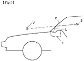
- These display devices for a vehicle are, for example, as shown in Fig. 9 , disposed in a dashboard of the vehicle and allow a vehicle driver 3 to visually recognize the virtual image of a display image V and landscape by superimposing them by irradiating display light L to a windshield 2.
- the display device for a vehicle further includes: a laser-resistant member in a scanning possible range of the scanning unit, in which the scanning unit driving means irradiates the laser-resistant member with the laser light by the scanning unit while the laser light source performs the self-heating drive.
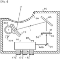
- Fig. 1 is a side view of a head-up display device for vehicles 1 of the embodiment
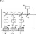
- Fig. 2 is an explanatory view of a combined laser light output unit 10 of the embodiment.
- the head-up display device for vehicles 1 includes the combined laser light output unit 10 for outputting combined laser light RGB, a color sensor (first light intensity detection means) 20 for receiving the combined laser light RGB and detecting a first light intensity that is a light intensity of each of the combined laser light RGB, a scanning unit 30 for allowing the combined laser light RGB to scan in a direction of a screen 40, the screen 40 onto which a display image M is projected by the light that is allowed to scan, a photo sensor (second light intensity detection means) 50 that is disposed on the screen 40 and detects a second light intensity that is the light intensity of the combined laser light RGB that is allowed to scan by the scanning unit 30, a plane mirror 60 that folds back display light L indicating the display image M that is projected onto the screen 40 to a concave mirror 70, the concave mirror 70 that emits the display light L to the windshield 2 via a light-transmitting unit 90 described below, a reflection means movement control unit 300 (angle adjusting means in the claims) that moves and
- the multiplexing means 15 is configured of a diachronic mirror that reflects light of a specific wavelength and transmits light of other wavelengths and the like.
- the multiplexing means 15 is configured by a first multiplexing unit 15a that reflects the red laser light R, second multiplexing means 15b that transmits the red laser light R and reflects the green laser light G, and third multiplexing means 15c that transmits the red laser light R and the green laser light G and reflects the blue laser light B.
- the Peltier element (auxiliary temperature raising means in the claims) 16 is a planar thermoelectric element using a Peltier effect.
- the Peltier element 16 is configured of a red Peltier element 16a that is connected to the red LD 11, a red Peltier element 16b that is connected to the green LD 12, and a blue Peltier element 16c that is connected to the blue LD 11.
- the heat is absorbed in one surface and is dissipated in the other surface by flowing a current and it is possible to reverse heat absorption and heat dissipation by reversing the flow of the current.
- the Peltier element 16 is provided for each of the LDs 11, 12, and 13, but may be shared by a plurality of LDs.
- the color sensor (first light intensity detection means) 20 receives some of the combined laser light RGB reflected from the permeable membrane 21, detects the first light intensity (red light intensity Ir of the red laser light R, green light intensity Ig of the green laser light G, and blue light intensity Ib of the blue laser light B) of the combined laser light RGB, and then outputs to the general control unit 400 described below via an A/D converter. Further, the first light intensity detection means 20 may be good as long as the light intensity is detected and thus, may be configured of photo diodes respectively provided at positions in which the red laser light R, the green laser light G, and the blue laser light B can be detected respectively other than the optical path of the combined laser light RGB.
- the screen 40 receives the display image M from the MEMS mirror 30 from the back side thereof, transmits and diffuses the image, and then displays the display image M on the front side.
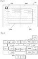
- the screen 40 is configured of a holographic diffuser, a micro lens array, a polarizer or the like. As shown in Fig. 3 , the screen 40 is classified into a display area 40a that is reflected by the plane mirror 60 and is viewed as the virtual image V to the vehicle driver 3, and a non-display area 40b that is not reflected by the plane mirror 60.
- the photo diode (second light intensity detection means) 50 is disposed in a region of the non-display area 40b of the screen 40 on the side of the MEMS mirror 30 of the screen 40 and a region in which the MEMS mirror 30 is capable of scanning, and detects the light intensity of the combined laser light RGB that is allowed to scan by the MEMS mirror 30.
- the photo diode 50 outputs the second light intensity that is the light intensity detected as an analog signal, converts the analog signal into a digital signal via an A/D converter, and outputs to the general control unit 400 described below.
- the plane mirror 60 is a plane mirror that folds back the display light L of the display image M projected in front surface of the screen 40 to the concave mirror 70 side.
- the light-transmitting unit 90 is fitted in the housing 80 described below, is made of translucent resin such as acryl, and is formed in a curved shape so that external light from the outside of the head-up display device for vehicles 1 is not reflected in a direction of the vehicle driver 3.
- the LD driving means (light source driving means in the claims) 101 inputs LD control data output from the general control unit 400 described below and allows each of the LDs 11, 12, and 13 to be PWM (Pulse Width Modulation) control, PAM (Pulse Amplitude Modulation) control, or DC (Direct Current) control based on the LD control data.
- the LD control data is classified as normal LD control data that drives each of the LDs 11, 12, and 13 in order to display a desired display image M and self-heating LD control data that causes the LDs 11, 12, and 13 to perform the self-heating drive under a low temperature environment and heats LDs 11, 12, and 13 themselves to be warm.
- the LD control means 101 DC-controls the LDs 11, 12, and 13 in the self-heating drive. As described above, By DC-controlling the LDs 11, 12, and 13 in this manner, more current can be flowed by the LDs 11, 12, and 13, thereby quickly raising the temperature of the LD.
- the LD current detection means 102 detects a current value flowing through the red LD 11, the green LD 12, and the blue LD 13, respectively, and outputs the LD current data indicating the current value to the LD driving means 101.
- the LD current detection means 102 always detects the current value flowing through the LDs 11, 12, and 13, but may detect only in a predetermined operation of the head-up display device for vehicles 1, or may detect for each predetermined period.
- the MEMS mirror driving means 201 is configured of a drive circuit of the MEMS mirror 30 and as shown in Fig. 3 , allows the combined laser light RGB to scan by vertical driving and horizontal driving of the MEMS mirror 30, based on the MEMS mirror control data from the general control unit 400.
- the MEMS mirror driving means 201 inputs the scanning position detection data that is output from the mirror position detection means 202 and calculates feedback data from the scanning position detection data, and outputs the feedback data to the general control unit 400 after driving MEMS mirror 30.
- the feedback data output from the MEMS mirror driving means 201 is data such as an actually measured resonance frequency that is the resonance frequency of the piezoelectric element when moving the mirror of the MEMS mirror 30 actually horizontally, an actually measured vertical driving frequency that is a horizontal frequency of the piezoelectric element when moving the mirror actually horizontally, and the like.
- the mirror position detection means 202 detects a position of the vibration for each time for the piezoelectric element moving the mirror of the MEMS mirror 30 and outputs the position to the MEMS mirror driving means 201 as scanning position detection data.
- the reflection means movement control unit 300 includes a motor 301 for adjusting the angle of the concave mirror 70, a motor drive unit 302 for driving the motor 301, and a concave mirror state detection unit 303 for detecting the angle of the concave mirror 70.
- the motor drive unit 302 drives the motor 301 and adjusts the concave mirror 70 at a desired angle based on the angle adjustment data from the general control unit 400.
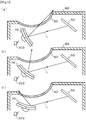
- An angle region in which the motor 301 can adjust the concave mirror 70 is classified as a visible position in which the concave mirror 70 irradiates the display light L from the light-transmitting unit 90 to the outside and an invisible position in which the concave mirror 70 does not irradiate the display light L from the light-transmitting unit 90 to the outside.
- the visible position is an angular position of the concave mirror 70 in the normal driving of the head-up display device for vehicles 1 of the embodiment, as shown in Fig. 5(b) , or is an angular position in which the concave mirror 70 irradiates the display light L from the light-transmitting unit 90 to the outside as shown in Figs. 5 (a) and (c) .
- the visible position it is possible to adjust a position (position in which the virtual image V is visible) in which the display light L is projected onto the windshield 2 by adjusting the angle of the concave mirror 70 by the operation of a push button switch (not shown) that is mounted on the vehicle.
- the invisible position is the angular position of the concave mirror 70 where the unnecessary display light L is not emitted from the light-transmitting unit 90.
- the motor 301 is shown as a common motor to adjust the angle of the concave mirror 70 to the invisible position and the visible position, and to adjust the position in which the display light L is projected onto the windshield 2 in the visible position, but may be provided separately.
- the motor 301 is intended to adjust the angle of the concave mirror 70, but it is possible to move the concave mirror 70 to the visible position and the invisible position.
- the motor drive unit 302 is a driver circuit of a stepping motor and drives the motor 301 based on the angle adjustment data output from the general control unit 400.
- the angular adjustment data is data for adjusting the angle relative to the predetermined original point of the concave mirror 70 described below and is recorded in advance in the recording means 402.
- the concave mirror state detection unit 303 is a mechanical switch for detecting whether the concave mirror 70 is in the original point and detects the contact and depression with one point of the concave mirror 70, and outputs the origin detection signal to the general control unit 400.
- the concave mirror state detection unit 303 detects only whether the concave mirror 70 is in the original point, but may perform the angle detection of the concave mirror 70 by using an angle sensor.
- the general control unit 400 is configured of a CPU 401 that is formed of a microcomputer, a FPGA (Field•Programmable•Gate•Array), an ASIC, and the like, and recording means 402 that is formed of EEPROM, Flash, and the like, and records programs and data that drive the CPU 401.
- the general control unit 400 controls the LD control unit 100, the scan control unit 200, and the reflection means movement control unit 300.
- the general control unit 400 inputs, from the vehicle ECU (not shown), LD current data indicating vehicle information, a start signal, or the current value flowing through the LDs 11, 12, and 13, temperature data indicating the detected temperature T of the LDs 11, 12, and 13 from the temperature detection unit 18, first light intensity data from the first light intensity detection means 20, second light intensity data from the second light intensity detection means 50, and feedback data from the scan control unit 200, and an origin detection signal indicating that the concave mirror 70 from the reflection means movement control unit 300 is in the origin position.
- the general control unit 400 generates and outputs LD drive data (normal LD control data, self-heating LD control data) for driving the LD control unit 100, scanning unit control data for driving the scan control unit 200, and an angle adjustment data for driving the reflection means movement control unit 300 from the above information, and overall controls the head-up display device for vehicles 1 of the embodiment.
- LD drive data normal LD control data, self-heating LD control data
- scanning unit control data for driving the scan control unit 200
- an angle adjustment data for driving the reflection means movement control unit 300 from the above information
- Fig. 7 is a view for describing how warm the combined laser light output unit 10 (LDs 11, 12, and 13) is based on the detected temperature T detected from the temperature detection means 18.
- the CPU 401 outputs the self-heating LD control data with respect to the LD driving means 101 when the detected temperature T that is detected by the temperature detection means 18 is lower than a first threshold value T1 (-10°C) that is recorded in the recording unit 402 in advance, and the LD driving means 101 causes the LDs 11, 12, and 13 to perform the self-heating drive.
- the self-heating drive performs self-heating by flowing a DC current in the LDs 11, 12, and 13. Therefore, as described above, it is possible to further quickly increase the temperature of the laser light source by driving the laser light source by the DC current.
- the magnitude of the current value is larger, it is possible to quickly increase the temperature, but the laser light source is driven at a current less than a current value in which the laser light source is destroyed and the currents flowing in the self-heating drive may be adjusted from the temperature or the current value that is actually flowed.
- the LD drive means 101 gradually reduces drive power of the LDs 11, 12, and 13 with increasing temperature of the LDs 11, 12, and 13 (for example, low current driving). The driving power is reduced and an excessive current to the laser light source due to the temperature rise of the laser light source is suppressed, and it is possible to prevent laser light source from being destroyed, based on the temperature rise in this way.
- the CPU 401 heats a surface that is connected to the LDs 11, 12, and 13 by applying a current to the Peltier element 16 and assists in raising the temperature of the LDs 11, 12, and 13.
- the CPU 401 stops the self-heating drive of the LDs 11, 12, and 13, and raises the temperature of the LDs 11, 12, and 13 only with the Peltier element 16.
- the CPU 401 does not perform the temperature rise due to the self-heating of the LDs 11, 12, and 13, or the temperature rise by the heating of the Peltier element 16.
- the CPU 401 normally drives the LDs 11, 12, and 13 via the LD control unit 100, and allows the MEMS mirror 30 to perform normally scanning via the scan unit 200, whereby the display image M is displayed on the screen 40.
- the LD control means 101 it is possible to prevent switching between the self-heating drive and the normal driving of the LDs 11, 12, and 13 with the LD control means 101 from being frequently performed by separately providing the first threshold value T1 that is a threshold of whether to perform or stop the self-heating drive of the LDs 11, 12, and 13, and the second threshold value T2 that is a threshold of whether to perform the normal driving to display the display image M (providing a temperature difference).
- the CPU 401 allows the current to flow in opposite to the current applied to the Peltier element 16 when heating, the heat of the LDs 11, 12, and 13 to be absorbed, and the heat to be dissipated through the heat sink 17.
- a fourth threshold value T4 the CPU 401 allows the current to flow in opposite to the current applied to the Peltier element 16 when heating, the heat of the LDs 11, 12, and 13 to be absorbed, and the heat to be dissipated through the heat sink 17.
- an oscillation threshold current value that is applied for laser oscillation is increased and the laser oscillation is not generated if a large amount of current is not applied. Therefore, the Peltier element 16 is controlled so that the temperature of the LDs 11, 12, and 13 is a temperature or more for stabilizing the output characteristics and heat absorption or heat dissipation are performed so as to lower the temperature as possible.
- the MEMS mirror 30 performs scanning when raising the temperature which allows the combined laser light RGB at a predetermined cycle to scan during the self-heating drive of the LDs 11, 12, and 13 (scanning unit driving means in the claims).
- the scanning when raising the temperature is a normal scanning that performs the horizontal scanning drive and the vertical scanning drive at a period that is similar when the LDs 11, 12, and 13 are normally driven, and the display light L generated by the normal scanning is not reflected toward the light-transmitting unit 90 by positioning the concave mirror 70 in the invisible position, and is not visually recognized by the vehicle driver 3.
- the scanning when raising the temperature may change the scanning position of the display light L to an extent that the screen 40 is not burned due to unnecessary display light L during self-heating drive of the LDs 11, 12, and 13, it is not necessary to scan always and the scanning unit 30 may repeatedly stop and perform the scanning at a predetermined cycle to the extent that the screen 40 is not burned.
- the unnecessary display light L during the self-heating is not emitted to the outside by making the concave mirror 70 to be in the invisible position, but in a second embodiment of the invention, the concave mirror 70 is not necessary to be in the invisible position, as shown in Fig. 8(a) , the LD driving means 101 causes the LDs 11, 12, and 13 to perform the self-heating drive at only timing in which the MEMS mirror 70 scans the non-display area 40b during the self-heating drive of the LDs 11, 12, and 13, and does not drive the LD in the display area 40a.
- unnecessary display light L may be prevented from being emitted to the outside.
- the MEMS mirror driving means 201 allows the MEMS mirror 70 to perform scanning only by the non-display area 40b while the LDs 11, 12, and 13 perform the self-heating drive, it is possible to prevent unnecessary display light L from being emitted to the outside in such a configuration similar to the embodiment described above.
- the combined laser light RGB when the LDs 11, 12, and 13 perform the self-heating drive is subjected to the scanning when raising the temperature on the screen 40 by the MEMS mirror 70.
- the MEMS mirror 70 does not operate normally and the combined laser light RGB is locally irradiated in a part of the screen 40 when the LDs 11, 12, and 13 perform the self-heating drive, and there is a concern that the screen 40 is burned.
- the fourth embodiment of the invention includes the attenuation element (attenuating unit) 22 that adjusts the transmittance (attenuating rate P) of the combined laser light RGB, on the optical path of the combined laser light RGB, and an attenuation element control unit (attenuation unit control means) 500 (see Fig. 11 ) that is configured of a drive circuit that controls the attenuating rate P of the attenuation element 22.
- the attenuation element (attenuation unit) 22 includes a pre-polarizing filter 220, a liquid crystal element 221, and a post-polarizing filter 222, and can prevent burning of the screen 40 by attenuating the laser light beams R, G, and B immediately after the start switch ON described below.
- the pre-polarizing filter 220 and the post-polarizing filter 222 are configured of a polarizing element that is durable in the laser light such as aluminum wire grid polarizing filter.
- the liquid crystal element 221 is configured of a liquid crystal element of a VA type (Vertical Alignment type) that is normally black mode where the transmittance is minimum (maximum attenuating rate Pm) during no voltage and adjusts the attenuating rate P based on the control signal from the attenuation element control unit 500.
- VA type Vertical Alignment type
- the liquid crystal element 221 is configured of the VA type, but may be configured of a reflection type, a transmission type LSOS (Liquid Crystal On Silicon) and the like.
- the attenuation element 22 can attenuate the laser light of the LDs 11, 12, and 13, it may be provided in each of the red laser light R, the green laser light G, and the blue laser light B rather than the optical path of the combined laser light RGB. Further, since the laser light is always irradiated on one point, for the attenuation element 22, it is preferable that a member having heat resistance or light resistance be used and it is preferable that each of them be connected to a heat dissipation member. Moreover, the attenuation element 22 is configured of the polarizing filter and the liquid crystal element, but, for example, may be configured of a variable concentration type ND filter as long as the laser light is attenuated.
- the attenuation element control unit (attenuation unit control means) 500 is configured of a VA liquid crystal voltage variable pulse waveform generating circuit composed of oscillation, integration, and amplifier circuits that adjust the polarization angle of the liquid crystal element 221. Attenuation element control unit 500 generates a liquid crystal driving pulse waveform of voltage of approximately 0 to ⁇ 20V from brightness adjustment data (PWM signal) that is electrically connected to the general control unit 400 and is input from the general control unit 400.
- PWM signal brightness adjustment data
- the attenuation element control unit 500 adjusts the polarization angle of the laser light by the liquid crystal element 221 from a voltage width of the liquid crystal driving pulse waveform and adjusts the attenuation amount P of the laser light by a difference from the transmission polarization angle of the post-polarizing filter 222.
- the general control unit 400 in the fourth embodiment inputs, from the vehicle ECU (not shown), the display brightness information and the start signal, the LD current data indicating the current value flowing through the LDs 11, 12, and 13, the temperature data indicating the detected temperature T of the LDs 11, 12, and 13 from the temperature detection means 18, the first light intensity data from the first light intensity detection means 20, the second light intensity data from the second light intensity detection means 50, the feedback data from the scan control unit 200, and the origin detection signal indicating that the concave mirror 70 from the reflecting means movement control unit 300 is in the original position.
- the general control unit 400 generates the brightness adjustment data for driving the attenuation element control unit 500 from the above information and adjusts the attenuation amount P of the laser light by the liquid crystal element 221 via the attenuation element control unit 500.
- the control configuration of the head-up display device for vehicles 1 of the fourth embodiment is described above and the operation step of the head-up display device for vehicles 1 according to the fourth embodiment will be described with reference to Figs. 12 to 15 .
- Fig. 12 is a view describing the time course of the LDs 11, 12, and 13, the Peltier element 16, the MEMS mirror 30, and the attenuation element 22 when the start time is t0 in the head-up display device for vehicles 1.
- CPU 401 outputs the self-heating LD control data with respect to the LD driving means 101 and the LD driving means 101 causes the LDs 11, 12, and 13 to perform the self-heating drive.
- the self-heating drive performs self-heating by flowing a DC current in the LDs 11, 12, and 13.
- the CPU 401 heats the surface that is connected to the LDs 11, 12, and 13 by applying the current to the Peltier element 16, and assists in raising the temperature of the LDs 11, 12, and 13.
- the MEMS mirror 30 performs the scanning when raising the temperature that allows the combined laser light RGB to scan to the screen 40 at a predetermined cycle while the LDs 11, 12, and 13 perform self-heating drive.
- the attenuation element 22 performs the attenuation when raising the temperature that attenuates the combined laser light RGB during this time.
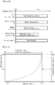
- Fig. 13 is a view showing a time course (solid line in Fig. 13 ) of the attenuating rate P of the attenuation element 22 with respect to an elapsed time t and a time course (dotted line in Fig. 13 ) of the scanning possible range Q of the MEMS mirror 70 with respect to the elapsed time t.
- the scanning possible range Q of the MEMS mirror 70 gradually increases from the time of starting (time t0) and the scanning can be performed by a range in the normal scanning at time tx.
- the MEMS mirror 70 can perform the horizontal scanning drive, and then can gradually perform the vertical scanning drive in an extensive range.
- the scanning possible range Q of the MEMS mirror 70 is widened.
- the screen 40 is likely to be burned as the scanning possible range Q of the MEMS mirror 70 is narrowed and the screen 40 is unlikely to be burned as the scanning possible range Q is widened.
- the general control unit 400 sends the brightness adjustment data of the maximum attenuating rate Pm to the attenuation element control unit 500 after the start switch is turned ON (time t0). Since the attenuation element 22 has characteristics of normally black, the brightness adjustment data of the maximum attenuating rate Pm is no voltage pulse waveform. Then, after the general control unit 400 determines that the MEMS mirror 70 becomes stable scanning (tx) by the feedback data from the scan control unit 200, the general control unit 400 sends arbitrary (request) brightness adjustment data Pn to the attenuation element control unit 500 based on the brightness information from the vehicle ECU and controls the attenuation element 22 (see Fig. 13 ).
- the liquid crystal element 22 is the normally black mode, it is possible to reliably attenuate the laser light immediately after the starting.
- the determination whether or not the MEMS mirror 70 performs stable scanning is not determined by the feedback data from the scan control unit 200 as described above, and a time tx expected until the stable scanning is performed is stored in the memory in advance and the attenuation when raising the temperature may be performed in the attenuation element 22 until a predetermined time (tx) is elapsed.
- Fig. 14 is a view showing a time course (solid line in Fig. 14 ) of a damage risk factor R of the screen 40 with respect to the elapsed time t and a time course (dotted line in Fig. 14 ) of the scanning possible range Q of the MEMS mirror 70 with respect to the elapsed time t.
- the damage risk factor R of the screen 40 varies with the scanning possible range Q of the MEMS mirror 70.
- the screen 40 is likely to be burned (the damage risk factor R increases) as the scanning possible range Q of the MEMS mirror 70 is narrowed, and the screen 40 is unlikely to be burned (damage risk factor R is reduced) as the scanning possible range Q of the MEMS mirror 70 is widened.
- the damage risk factor R has an inverse proportional relationship to the scanning possible range Q of the MEMS mirror 70. Therefore, as shown in Fig. 15 , the attenuating rate P of the attenuation element 22 may be controlled to be gradually decreased in a manner in which the attenuating rate P is inversely proportional to the increase (reduction of the damage risk factor R) in the scanning possible range Q.
- the attenuation element 22 is disposed in the LDs 11, 12, and 13 respectively and the self-heating drive range is different in each LD, only attenuation element to be paired with the LD performing the self-heating drive may perform the attenuation when raising the temperature.
- the temperature detection is performed by the temperature detection unit 18 as described above and the control whether or not the LDs 11, 12, and 13 perform the self-heating drive in under a low temperature environment is performed at the time of starting of the head-up display device for vehicles 1.
- the head-up display device for vehicles 1 is started by ON of a start switch (ignition (hereinafter, IGN), accessories (hereinafter ACC), or key unlocking) of the vehicle and the detected temperature T is detected at the temperature detection unit 18, and the temperature rising control is performed based on the detected temperature T if necessary.
- IGN ignition
- ACC accessories
- the temperature rising control is performed in the Peltier element 16 and the Peltier element 16 is driven so that the detected temperature T does not become a second threshold value T2 or less, and it is preferable that the self-heating drive be not performed by stopping the normal driving of the LDs 11, 12 and 13.
- the self-heating drive may be performed for a predetermined time and then the normal driving may be performed.
- the light intensity that is detected by the color sensor 20 or the photo diode 50 reaches a predetermined value, it may be assumed that the LDs 11, 12, and 13 are heated and the self-heating drive may be stopped.
- a laser-resistant member that is a ultra-high temperature resistant material such as a heat-resistant superalloy or ceramic on the screen 40 of the scanning region of the MEMS mirror 30 may be further included and the MEMS mirror driving means 201 may irradiate the combined laser light RGB on the laser-resistant member by the MEMS mirror 30 while the LDs 11, 12, and 13 perform the self-heating drive.
- the laser-resistant members may be provided in a plurality of portions on the screen 40 of the scanning region of the MEMS mirror 30 and the laser-resistant members on which the combined laser light RGB is irradiated may be switched at a predetermined cycle.
- the invention relates to the display device for a vehicle and, for example, can be applied to a display device for a vehicle information display that is mounted on a mobile body such as an automobile and projects the display image on the windshield of the vehicle to display the virtual image.
Landscapes
- Physics & Mathematics (AREA)
- General Physics & Mathematics (AREA)
- Optics & Photonics (AREA)
- Engineering & Computer Science (AREA)
- Chemical & Material Sciences (AREA)
- Combustion & Propulsion (AREA)
- Transportation (AREA)
- Mechanical Engineering (AREA)
- Multimedia (AREA)
- Signal Processing (AREA)
- Condensed Matter Physics & Semiconductors (AREA)
- Electromagnetism (AREA)
- Instrument Panels (AREA)
- Control Of Indicators Other Than Cathode Ray Tubes (AREA)
- Devices For Indicating Variable Information By Combining Individual Elements (AREA)
- Mechanical Optical Scanning Systems (AREA)
- Liquid Crystal (AREA)
Claims (10)
- Anzeigevorrichtung für ein Fahrzeug (1), die Folgendes umfasst:ein Gehäuse (80), das ausgelegt ist zum Aufweisen einer Lichtsendeeinheit (90) zum Senden von Licht;eine Laserlichtquelle (11, 12, 13) zum Emittieren von Laserlicht;ein Lichtquellentreibermittel (101) zum Treiben der Laserlichtquelle (11, 12, 13);eine Scannereinheit (30) zum Erzeugen eines Bildes (M) durch Scannen des Laserlichts;ein Scannereinheittreibermittel (201) zum Treiben der Scannereinheit (30); undein Reflexionsmittel (70) zum Reflektieren von Anzeigelicht, das das Bild (M) anzeigt, in einer Richtung der Lichtsendeeinheit (90); wobei die Anzeigevorrichtung dadurch gekennzeichnet ist, dass sie Folgendes umfasst:ein Temperaturdetektionsmittel (18) zum Detektieren der Temperatur der Laserlichtquelle (11, 12, 13), wobei das Lichtquellentreibermittel (101) die Laserlichtquelle (11, 12, 13) veranlasst, ein Selbstheiztreiben durchzuführen, wenn die detektierte Temperatur (T), die von dem Temperaturdetektionsmittel (18) detektiert wird, niedriger als ein erster Schwellenwert (T1) ist, der im Voraus bestimmt wird; und das Selbstheiztreiben stoppt, wenn die detektierte Temperatur über dem ersten Schwellenwert (T1) liegt, wobei die Laserlichtquelle (11, 12, 13) normales Treiben durchführt, um das Anzeigebild (M) anzuzeigen, wenn die detektierte Temperatur (T) höher als ein zweiter Schwellenwert (T2) liegt, das heißt eine Temperatur, die höher als der erste Schwellenwert (T1) liegt; undein Hilfstemperaturanhebemittel (16) zum Anheben der Temperatur der Laserlichtquelle (11, 12, 13),wobei das Hilfstemperaturanhebemittel (16) die Temperatur der Laserlichtquelle (11, 12, 13) anhebt, wenn die detektierte Temperatur (T) zwischen dem ersten Schwellenwert (T1) und einem dritten Schwellenwert (T3) liegt, das heißt eine Temperatur, die höher als der zweite Schwellenwert (T2) liegt, und stoppt, die Temperatur der Laserquelle anzuheben, wenn die detektierte Temperatur über dem dritten Schwellenwert (T3) liegt.
- Anzeigevorrichtung für ein Fahrzeug nach Anspruch 1,
wobei die Scannereinheit (30) beim Anheben der Temperatur ein Scannen durchführt, bei dem das Laserlicht durch die Scannereinheit (30) in einem vorbestimmten Zyklus gescannt wird, während die Laserlichtquelle (11, 12, 13) das Selbstheiztreiben durchführt. - Anzeigevorrichtung für ein Fahrzeug (1) nach Anspruch 1,
wobei die Laserlichtquelle (11, 12, 13) das Selbstheiztreiben zum Anheben der Temperatur der Laserlichtquelle (11, 12, 13) durch Bestromen der Laserlichtquelle (11, 12, 13) mit Gleichstrom durchführt. - Anzeigevorrichtung für ein Fahrzeug (1) nach Anspruch 1, die ferner Folgendes umfasst:ein Winkeleinstellmittel (300) zum Einstellen des Reflexionsmittels (70) auf einen gewünschten Winkel,wobei das Winkeleinstellmittel (300) eine Stellung des Reflexionsmittels (70) erlaubt, die eine unsichtbare Stellung ist, bei der das Laserlicht in das Gehäuse (80) reflektiert wird, während die Laserlichtquelle (11, 12, 13) das Selbstheiztreiben durchführt.
- Anzeigevorrichtung für ein Fahrzeug (1) nach Anspruch 1,
wobei die Scannereinheit (30) das Laserlicht in ein Nichtanzeigegebiet (40b) scannt, das eine Region ist, in der das Bild durch die Scannereinheit (30) nicht in einer scanbaren Region angezeigt wird. - Anzeigevorrichtung für ein Fahrzeug (1) nach Anspruch 1,
wobei das Hilfstemperaturanhebemittel (16) ein Peltier-Element ist. - Anzeigevorrichtung für ein Fahrzeug (1) nach Anspruch 1,
wobei das Lichtquellentreibermittel (101), basierend auf einer Zunahme der detektierten Temperatur (T), graduell die Treiberleistung der Laserlichtquelle (11, 12, 13) verringert. - Anzeigevorrichtung für ein Fahrzeug (1) nach Anspruch 1, die ferner Folgendes umfasst:ein laserfestes Element in einer scanbaren Region der Scannereinheit (30),wobei das Scannereinheittreibermittel (201) das laserfeste Element mit dem Laserlicht von der Scannereinheit (30) bestrahlt, während die Laserlichtquelle (11, 12, 13) das Selbstheiztreiben durchführt.
- Anzeigevorrichtung für ein Fahrzeug (1) nach Anspruch 1, die ferner Folgendes umfasst:eine Abschwächeinheit (22), die auf einem optischen Pfad von der Laserlichtquelle (11, 12, 13) zur Scannereinheit (30) angeordnet ist; undein Abschwächeinheittreibermittel zum Treiben der Abschwächeinheit (22),wobei die Abschwächeinheit (22) die Abschwächung beim Anheben der Temperatur durchführt, während das Lichtquellentreibermittel (101) das Selbstheiztreiben durchführt.
- Anzeigevorrichtung für ein Fahrzeug (1) nach Anspruch 9,
wobei die Abschwächeinheit (22) ein Flüssigkristallelement und ein Polarisationsfilter aufweist, und
wobei das Flüssigkristallelement eine im Ruhezustand schwarze Charakteristik aufweist.
Applications Claiming Priority (3)
| Application Number | Priority Date | Filing Date | Title |
|---|---|---|---|
| JP2012072643 | 2012-03-28 | ||
| JP2013005312A JP6107153B2 (ja) | 2012-03-28 | 2013-01-16 | 車両用表示装置 |
| PCT/JP2013/056257 WO2013146157A1 (ja) | 2012-03-28 | 2013-03-07 | 車両用表示装置 |
Publications (3)
| Publication Number | Publication Date |
|---|---|
| EP2833193A1 EP2833193A1 (de) | 2015-02-04 |
| EP2833193A4 EP2833193A4 (de) | 2015-10-28 |
| EP2833193B1 true EP2833193B1 (de) | 2017-07-19 |
Family
ID=49259425
Family Applications (1)
| Application Number | Title | Priority Date | Filing Date |
|---|---|---|---|
| EP13768673.9A Not-in-force EP2833193B1 (de) | 2012-03-28 | 2013-03-07 | Anzeigevorrichtung für ein fahrzeug |
Country Status (4)
| Country | Link |
|---|---|
| US (1) | US9459452B2 (de) |
| EP (1) | EP2833193B1 (de) |
| JP (1) | JP6107153B2 (de) |
| WO (1) | WO2013146157A1 (de) |
Families Citing this family (64)
| Publication number | Priority date | Publication date | Assignee | Title |
|---|---|---|---|---|
| JP6163033B2 (ja) * | 2013-07-10 | 2017-07-12 | 矢崎総業株式会社 | ヘッドアップディスプレイ装置及び表示ユニット |
| JP6387589B2 (ja) * | 2013-08-30 | 2018-09-12 | 株式会社リコー | 画像形成装置、車両、及び画像形成装置の制御方法 |
| JP6194256B2 (ja) * | 2014-01-29 | 2017-09-06 | 富士フイルム株式会社 | 投映システムおよびプロジェクター |
| JP6311966B2 (ja) * | 2014-02-17 | 2018-04-18 | 株式会社リコー | 光照射装置及びこれを備えた画像表示装置 |
| EP3125223B1 (de) * | 2014-03-28 | 2019-08-14 | JVC Kenwood Corporation | Bildanzeigevorrichtung und bildanzeigeeinstellungsverfahren |
| US10001646B2 (en) * | 2014-05-14 | 2018-06-19 | Denso Corporation | Head-up display |
| CN106471417B (zh) * | 2014-06-13 | 2019-03-12 | 三菱电机株式会社 | 虚像显示装置以及车辆的头戴式显示器 |
| JP6394113B2 (ja) * | 2014-06-27 | 2018-09-26 | 船井電機株式会社 | プロジェクタおよびヘッドアップディスプレイ装置 |
| JP6673632B2 (ja) * | 2014-09-08 | 2020-03-25 | ファナック株式会社 | レーザ光を高速で走査可能なガルバノスキャナを含む光造形加工機 |
| US10232776B2 (en) * | 2014-11-14 | 2019-03-19 | Continental Automotive Systems, Inc. | Display system for mirror-less driving |
| JP6295981B2 (ja) * | 2015-02-25 | 2018-03-20 | 株式会社Jvcケンウッド | 画像描画装置、ヘッドアップディスプレイ及び画像輝度調整方法 |
| JP6509601B2 (ja) * | 2015-03-18 | 2019-05-08 | アルプスアルパイン株式会社 | 画像表示装置 |
| JP6558017B2 (ja) * | 2015-03-27 | 2019-08-14 | 日本精機株式会社 | ヘッドアップディスプレイ |
| US9810903B2 (en) * | 2015-07-28 | 2017-11-07 | Kabushiki Kaisha Toshiba | Optical scanner |
| JP6613984B2 (ja) * | 2015-09-03 | 2019-12-04 | 株式会社Jvcケンウッド | 描画装置及び描画方法 |
| JP6735023B2 (ja) * | 2015-09-29 | 2020-08-05 | 株式会社リコー | 表示画像作成装置および画像表示装置 |
| EP3358403A4 (de) * | 2015-09-30 | 2019-04-24 | Nippon Seiki Co., Ltd. | Anzeigevorrichtung |
| CN105207058A (zh) * | 2015-10-10 | 2015-12-30 | 杭州虹视科技有限公司 | 白光激光模组、激光显示系统和激光投影系统 |
| CN105892041B (zh) * | 2015-11-19 | 2018-05-01 | 中国工程物理研究院应用电子学研究所 | 基于跟踪探测器的多路激光发射光轴调节装置及方法 |
| JP6582943B2 (ja) | 2015-12-04 | 2019-10-02 | 株式会社Jvcケンウッド | 描画装置及び描画方法 |
| US10302938B2 (en) * | 2016-02-08 | 2019-05-28 | Panasonic Intellectual Property Management Co., Ltd. | Light source device and image display apparatus |
| JP6907488B2 (ja) * | 2016-02-15 | 2021-07-21 | 株式会社リコー | 光源装置、画像表示装置及び物体装置 |
| WO2017183556A1 (ja) * | 2016-04-20 | 2017-10-26 | 日本精機株式会社 | ヘッドアップディスプレイ装置 |
| WO2017195740A1 (ja) * | 2016-05-09 | 2017-11-16 | 日本精機株式会社 | ヘッドアップディスプレイ装置 |
| US10274725B2 (en) * | 2016-06-20 | 2019-04-30 | Denso International America, Inc. | Head-up display with second high intensity lighting unit installed outside of first display casing |
| JP6805587B2 (ja) * | 2016-07-08 | 2020-12-23 | 株式会社リコー | 光源装置、画像表示装置及び物体装置 |
| WO2018084076A1 (ja) | 2016-11-04 | 2018-05-11 | 富士フイルム株式会社 | ウインドシールドガラス、ヘッドアップディスプレイシステム、およびハーフミラーフィルム |
| JP6907549B2 (ja) * | 2017-01-19 | 2021-07-21 | 住友電気工業株式会社 | 車載用ヘッドアップディスプレイ装置 |
| EP3584626B1 (de) * | 2017-02-17 | 2021-10-27 | Nippon Seiki Co., Ltd. | Head-up-anzeigevorrichtung |
| JP6891589B2 (ja) | 2017-03-28 | 2021-06-18 | セイコーエプソン株式会社 | 画像表示装置およびヘッドマウントディスプレイ |
| KR101945810B1 (ko) * | 2017-05-26 | 2019-02-08 | 엘지전자 주식회사 | 스캐닝 프로젝터 |
| JP7161997B2 (ja) | 2017-09-07 | 2022-10-27 | 富士フイルム株式会社 | 投映像表示用ハーフミラーフィルム、投映像表示用の合わせガラス、および、画像表示システム |
| JP2019056745A (ja) * | 2017-09-20 | 2019-04-11 | セイコーエプソン株式会社 | ヘッドマウントディスプレイ及び画像表示装置 |
| JP6756326B2 (ja) * | 2017-11-09 | 2020-09-16 | 株式会社デンソー | 状態検出装置 |
| TWI645220B (zh) * | 2017-12-01 | 2018-12-21 | 英錡科技股份有限公司 | 使用全像元件之車用抬頭顯示器 |
| CN107861248B (zh) * | 2017-12-25 | 2023-12-26 | 歌尔光学科技有限公司 | 激光束扫描显示设备及增强现实眼镜 |
| CN110068925B (zh) * | 2018-01-23 | 2022-12-06 | 松下知识产权经营株式会社 | 图像显示装置 |
| JP7140504B2 (ja) * | 2018-02-14 | 2022-09-21 | 矢崎総業株式会社 | 投影表示装置 |
| JP6934101B2 (ja) | 2018-02-23 | 2021-09-08 | 富士フイルム株式会社 | 画像表示用合わせガラスの製造方法、画像表示用合わせガラス、および、画像表示システム |
| JP2019185002A (ja) * | 2018-04-11 | 2019-10-24 | ソニー株式会社 | 顕微鏡システム及び医療用光源装置 |
| CN110471181B (zh) * | 2018-05-11 | 2022-02-18 | 矢崎总业株式会社 | 车辆用显示装置 |
| JP7098483B2 (ja) * | 2018-08-31 | 2022-07-11 | キヤノン株式会社 | 光源装置および画像投射装置 |
| KR20200042660A (ko) * | 2018-10-16 | 2020-04-24 | 현대자동차주식회사 | 차량 디스플레이 제어 장치, 그를 포함한 시스템 및 그 방법 |
| EP3869245A4 (de) | 2018-10-17 | 2021-12-15 | FUJIFILM Corporation | Projektionsbildanzeigeelement, windschutzscheibenglas und headup-anzeigesystem |
| EP3657232B1 (de) * | 2018-11-08 | 2023-01-04 | Ricoh Company, Ltd. | Anzeigevorrichtung, anzeigesystem und mobiles objekt |
| JP7299920B2 (ja) | 2018-12-10 | 2023-06-28 | 富士フイルム株式会社 | 投映像表示用部材、ウインドシールドガラスおよびヘッドアップディスプレイシステム |
| CN113498487B (zh) | 2019-03-06 | 2023-07-04 | 富士胶片株式会社 | 投影图像显示用层叠膜、投影图像显示用的夹层玻璃及图像显示系统 |
| JP7403290B2 (ja) * | 2019-11-27 | 2023-12-22 | 京セラ株式会社 | ヘッドアップディスプレイシステムおよび移動体 |
| JP7032003B2 (ja) * | 2020-03-10 | 2022-03-08 | 矢崎総業株式会社 | 車両用表示装置 |
| JP7454649B2 (ja) | 2020-03-30 | 2024-03-22 | 富士フイルム株式会社 | 反射フィルム、ウインドシールドガラスおよびヘッドアップディスプレイシステム |
| WO2021200652A1 (ja) | 2020-03-30 | 2021-10-07 | 富士フイルム株式会社 | 直線偏光反射フィルム、ウインドシールドガラスおよびヘッドアップディスプレイシステム |
| CN115698783A (zh) | 2020-06-03 | 2023-02-03 | 富士胶片株式会社 | 反射膜、夹层玻璃的制造方法及夹层玻璃 |
| US20220055479A1 (en) * | 2020-08-24 | 2022-02-24 | Conserve & Associates , Inc. | Vehicular head-up display system with virtual images in different distances |
| US11169377B1 (en) * | 2020-09-16 | 2021-11-09 | E-Lead Electronic Co., Ltd. | Multi-focal plane head-up display |
| JP7764389B2 (ja) | 2020-10-09 | 2025-11-05 | 富士フイルム株式会社 | 反射フィルム、ウインドシールドガラス、および、ヘッドアップディスプレイシステム |
| WO2022123946A1 (ja) | 2020-12-09 | 2022-06-16 | 富士フイルム株式会社 | 反射フィルム、ウインドシールドガラスおよびヘッドアップディスプレイシステム |
| JP7521480B2 (ja) * | 2021-05-10 | 2024-07-24 | トヨタ自動車株式会社 | 表示制御装置、表示システム、車両、表示制御方法および表示制御プログラム |
| FR3125895B1 (fr) * | 2021-07-30 | 2026-04-17 | Valeo Comfort & Driving Assistance | Dispositif de génération d’images et afficheur tête haute comportant un tel dispositif |
| WO2023048293A1 (ja) | 2021-09-27 | 2023-03-30 | 日本精機株式会社 | 照明装置、及び、ヘッドアップディスプレイ |
| WO2023054324A1 (ja) | 2021-09-30 | 2023-04-06 | 富士フイルム株式会社 | ヘッドアップディスプレイシステム及び輸送機 |
| CN118302708A (zh) | 2021-11-05 | 2024-07-05 | 富士胶片株式会社 | 虚像显示装置、平视显示系统及运输机 |
| CN117750569A (zh) * | 2022-09-14 | 2024-03-22 | 昆山扬皓光电有限公司 | 投影装置以及投影装置的操作方法 |
| JP2024080786A (ja) * | 2022-12-05 | 2024-06-17 | キヤノン株式会社 | 情報処理装置、表示システム、移動体、情報処理方法、及びコンピュータプログラム |
| JPWO2024185844A1 (de) | 2023-03-08 | 2024-09-12 |
Family Cites Families (17)
| Publication number | Priority date | Publication date | Assignee | Title |
|---|---|---|---|---|
| JPH01237673A (ja) * | 1988-03-18 | 1989-09-22 | Canon Inc | 画像形成装置 |
| JPH07270711A (ja) | 1994-03-30 | 1995-10-20 | Canon Inc | 情報表示装置 |
| JP2002341280A (ja) * | 2001-05-16 | 2002-11-27 | Canon Inc | 投影型表示装置、及び該装置における光ビーム射出防止方法 |
| US7056035B2 (en) * | 2001-12-21 | 2006-06-06 | The Furukawa Electric Co., Ltd. | Optical module, optical apparatus including optical module, and method for using optical module |
| JP4043886B2 (ja) * | 2002-02-12 | 2008-02-06 | 古河電気工業株式会社 | 半導体レーザ装置の起動方法及び半導体レーザ装置を用いた光通信機器 |
| JP2004356579A (ja) * | 2003-05-30 | 2004-12-16 | Toshiba Corp | レーザ光出力装置、映像表示装置、および半導体レーザの駆動制御方法 |
| JP4285447B2 (ja) * | 2005-06-20 | 2009-06-24 | セイコーエプソン株式会社 | レーザ光源装置、表示装置およびプロジェクタ |
| JP4449976B2 (ja) * | 2006-12-26 | 2010-04-14 | セイコーエプソン株式会社 | 外部共振型レーザ光源装置 |
| US9172209B2 (en) * | 2007-02-01 | 2015-10-27 | Finisar Corporation | Resistive heating element for enabling laser operation |
| JP4864858B2 (ja) * | 2007-11-16 | 2012-02-01 | 富士通株式会社 | 波長可変レーザ光発生装置 |
| JP2010237238A (ja) * | 2009-03-30 | 2010-10-21 | Nippon Seiki Co Ltd | 表示装置 |
| US20100302463A1 (en) * | 2009-05-27 | 2010-12-02 | Sanyo Electric Co., Ltd. | Projection video display device |
| JP5493578B2 (ja) * | 2009-08-12 | 2014-05-14 | 船井電機株式会社 | プロジェクタ |
| JP5673544B2 (ja) * | 2009-09-28 | 2015-02-18 | コニカミノルタ株式会社 | レーザー投射装置 |
| US20120057136A1 (en) * | 2010-09-02 | 2012-03-08 | Panasonic Corporation | Image display apparatus |
| JP4725685B1 (ja) * | 2010-09-02 | 2011-07-13 | パナソニック株式会社 | 画像表示装置 |
| JP4761004B1 (ja) * | 2010-11-26 | 2011-08-31 | パナソニック株式会社 | 画像表示装置 |
-
2013
- 2013-01-16 JP JP2013005312A patent/JP6107153B2/ja not_active Expired - Fee Related
- 2013-03-07 US US14/388,752 patent/US9459452B2/en active Active
- 2013-03-07 EP EP13768673.9A patent/EP2833193B1/de not_active Not-in-force
- 2013-03-07 WO PCT/JP2013/056257 patent/WO2013146157A1/ja not_active Ceased
Non-Patent Citations (1)
| Title |
|---|
| None * |
Also Published As
| Publication number | Publication date |
|---|---|
| EP2833193A1 (de) | 2015-02-04 |
| JP2013228674A (ja) | 2013-11-07 |
| WO2013146157A1 (ja) | 2013-10-03 |
| EP2833193A4 (de) | 2015-10-28 |
| US20150092118A1 (en) | 2015-04-02 |
| JP6107153B2 (ja) | 2017-04-05 |
| US9459452B2 (en) | 2016-10-04 |
Similar Documents
| Publication | Publication Date | Title |
|---|---|---|
| EP2833193B1 (de) | Anzeigevorrichtung für ein fahrzeug | |
| JP6202384B2 (ja) | レーザ光源制御装置および車両用表示装置 | |
| US9081184B2 (en) | Head-up display device for vehicle and self-checking method therefor | |
| TWI627445B (zh) | Display device | |
| JP2013164482A (ja) | 車両用ヘッドアップディスプレイ装置 | |
| US9715116B2 (en) | Color mixing device and display device | |
| JP2010237238A (ja) | 表示装置 | |
| JP2011090076A (ja) | 画像表示装置 | |
| JPWO2011132407A1 (ja) | 画像表示装置 | |
| CN110908124A (zh) | 一种hud光路系统及其控制方法、hud显示装置 | |
| JP6694742B2 (ja) | レーザ投射表示装置 | |
| JPWO2017061000A1 (ja) | ヘッドアップディスプレイ装置 | |
| JP6108169B2 (ja) | 混色装置及び表示装置 | |
| KR20080049637A (ko) | 레이저 광원 장치의 구동 방법, 레이저 광원 장치, 화상표시 장치, 모니터 장치, 조명 장치 | |
| JP6709515B2 (ja) | 表示装置 | |
| JP2015044511A (ja) | 車両用表示装置 | |
| WO2015146618A1 (ja) | レーザー光強度調整装置 | |
| CN211014860U (zh) | 一种hud光路系统及hud显示装置 | |
| CN115279617A (zh) | 平视显示装置 | |
| JP6146161B2 (ja) | 混色装置及び表示装置 | |
| JP6296282B2 (ja) | 車両用表示装置 | |
| JP2018121288A (ja) | 表示装置及びヘッドアップディスプレイ装置 | |
| JP2017165293A (ja) | 車両用表示装置 | |
| JP4858182B2 (ja) | 光源装置、プロジェクタ、及び光源装置の制御方法 | |
| JP2019133048A (ja) | 車両用の液晶表示ユニット及びヘッドアップディスプレイ装置 |
Legal Events
| Date | Code | Title | Description |
|---|---|---|---|
| PUAI | Public reference made under article 153(3) epc to a published international application that has entered the european phase |
Free format text: ORIGINAL CODE: 0009012 |
|
| 17P | Request for examination filed |
Effective date: 20141022 |
|
| AK | Designated contracting states |
Kind code of ref document: A1 Designated state(s): AL AT BE BG CH CY CZ DE DK EE ES FI FR GB GR HR HU IE IS IT LI LT LU LV MC MK MT NL NO PL PT RO RS SE SI SK SM TR |
|
| AX | Request for extension of the european patent |
Extension state: BA ME |
|
| DAX | Request for extension of the european patent (deleted) | ||
| RA4 | Supplementary search report drawn up and despatched (corrected) |
Effective date: 20150924 |
|
| RIC1 | Information provided on ipc code assigned before grant |
Ipc: G02B 26/10 20060101ALI20150918BHEP Ipc: H01S 5/024 20060101ALI20150918BHEP Ipc: G02B 27/01 20060101AFI20150918BHEP Ipc: B60K 35/00 20060101ALI20150918BHEP |
|
| GRAP | Despatch of communication of intention to grant a patent |
Free format text: ORIGINAL CODE: EPIDOSNIGR1 |
|
| INTG | Intention to grant announced |
Effective date: 20170313 |
|
| GRAS | Grant fee paid |
Free format text: ORIGINAL CODE: EPIDOSNIGR3 |
|
| GRAA | (expected) grant |
Free format text: ORIGINAL CODE: 0009210 |
|
| AK | Designated contracting states |
Kind code of ref document: B1 Designated state(s): AL AT BE BG CH CY CZ DE DK EE ES FI FR GB GR HR HU IE IS IT LI LT LU LV MC MK MT NL NO PL PT RO RS SE SI SK SM TR |
|
| REG | Reference to a national code |
Ref country code: GB Ref legal event code: FG4D |
|
| REG | Reference to a national code |
Ref country code: CH Ref legal event code: EP |
|
| REG | Reference to a national code |
Ref country code: IE Ref legal event code: FG4D |
|
| REG | Reference to a national code |
Ref country code: AT Ref legal event code: REF Ref document number: 910931 Country of ref document: AT Kind code of ref document: T Effective date: 20170815 |
|
| REG | Reference to a national code |
Ref country code: DE Ref legal event code: R096 Ref document number: 602013023788 Country of ref document: DE |
|
| REG | Reference to a national code |
Ref country code: NL Ref legal event code: MP Effective date: 20170719 |
|
| REG | Reference to a national code |
Ref country code: LT Ref legal event code: MG4D |
|
| REG | Reference to a national code |
Ref country code: AT Ref legal event code: MK05 Ref document number: 910931 Country of ref document: AT Kind code of ref document: T Effective date: 20170719 |
|
| PG25 | Lapsed in a contracting state [announced via postgrant information from national office to epo] |
Ref country code: HR Free format text: LAPSE BECAUSE OF FAILURE TO SUBMIT A TRANSLATION OF THE DESCRIPTION OR TO PAY THE FEE WITHIN THE PRESCRIBED TIME-LIMIT Effective date: 20170719 Ref country code: SE Free format text: LAPSE BECAUSE OF FAILURE TO SUBMIT A TRANSLATION OF THE DESCRIPTION OR TO PAY THE FEE WITHIN THE PRESCRIBED TIME-LIMIT Effective date: 20170719 Ref country code: NO Free format text: LAPSE BECAUSE OF FAILURE TO SUBMIT A TRANSLATION OF THE DESCRIPTION OR TO PAY THE FEE WITHIN THE PRESCRIBED TIME-LIMIT Effective date: 20171019 Ref country code: AT Free format text: LAPSE BECAUSE OF FAILURE TO SUBMIT A TRANSLATION OF THE DESCRIPTION OR TO PAY THE FEE WITHIN THE PRESCRIBED TIME-LIMIT Effective date: 20170719 Ref country code: LT Free format text: LAPSE BECAUSE OF FAILURE TO SUBMIT A TRANSLATION OF THE DESCRIPTION OR TO PAY THE FEE WITHIN THE PRESCRIBED TIME-LIMIT Effective date: 20170719 Ref country code: FI Free format text: LAPSE BECAUSE OF FAILURE TO SUBMIT A TRANSLATION OF THE DESCRIPTION OR TO PAY THE FEE WITHIN THE PRESCRIBED TIME-LIMIT Effective date: 20170719 Ref country code: NL Free format text: LAPSE BECAUSE OF FAILURE TO SUBMIT A TRANSLATION OF THE DESCRIPTION OR TO PAY THE FEE WITHIN THE PRESCRIBED TIME-LIMIT Effective date: 20170719 |
|
| REG | Reference to a national code |
Ref country code: FR Ref legal event code: PLFP Year of fee payment: 6 |
|
| PG25 | Lapsed in a contracting state [announced via postgrant information from national office to epo] |
Ref country code: IS Free format text: LAPSE BECAUSE OF FAILURE TO SUBMIT A TRANSLATION OF THE DESCRIPTION OR TO PAY THE FEE WITHIN THE PRESCRIBED TIME-LIMIT Effective date: 20171119 Ref country code: ES Free format text: LAPSE BECAUSE OF FAILURE TO SUBMIT A TRANSLATION OF THE DESCRIPTION OR TO PAY THE FEE WITHIN THE PRESCRIBED TIME-LIMIT Effective date: 20170719 Ref country code: LV Free format text: LAPSE BECAUSE OF FAILURE TO SUBMIT A TRANSLATION OF THE DESCRIPTION OR TO PAY THE FEE WITHIN THE PRESCRIBED TIME-LIMIT Effective date: 20170719 Ref country code: PL Free format text: LAPSE BECAUSE OF FAILURE TO SUBMIT A TRANSLATION OF THE DESCRIPTION OR TO PAY THE FEE WITHIN THE PRESCRIBED TIME-LIMIT Effective date: 20170719 Ref country code: GR Free format text: LAPSE BECAUSE OF FAILURE TO SUBMIT A TRANSLATION OF THE DESCRIPTION OR TO PAY THE FEE WITHIN THE PRESCRIBED TIME-LIMIT Effective date: 20171020 Ref country code: BG Free format text: LAPSE BECAUSE OF FAILURE TO SUBMIT A TRANSLATION OF THE DESCRIPTION OR TO PAY THE FEE WITHIN THE PRESCRIBED TIME-LIMIT Effective date: 20171019 Ref country code: RS Free format text: LAPSE BECAUSE OF FAILURE TO SUBMIT A TRANSLATION OF THE DESCRIPTION OR TO PAY THE FEE WITHIN THE PRESCRIBED TIME-LIMIT Effective date: 20170719 |
|
| REG | Reference to a national code |
Ref country code: DE Ref legal event code: R097 Ref document number: 602013023788 Country of ref document: DE |
|
| PG25 | Lapsed in a contracting state [announced via postgrant information from national office to epo] |
Ref country code: CZ Free format text: LAPSE BECAUSE OF FAILURE TO SUBMIT A TRANSLATION OF THE DESCRIPTION OR TO PAY THE FEE WITHIN THE PRESCRIBED TIME-LIMIT Effective date: 20170719 Ref country code: RO Free format text: LAPSE BECAUSE OF FAILURE TO SUBMIT A TRANSLATION OF THE DESCRIPTION OR TO PAY THE FEE WITHIN THE PRESCRIBED TIME-LIMIT Effective date: 20170719 Ref country code: DK Free format text: LAPSE BECAUSE OF FAILURE TO SUBMIT A TRANSLATION OF THE DESCRIPTION OR TO PAY THE FEE WITHIN THE PRESCRIBED TIME-LIMIT Effective date: 20170719 |
|
| PLBE | No opposition filed within time limit |
Free format text: ORIGINAL CODE: 0009261 |
|
| STAA | Information on the status of an ep patent application or granted ep patent |
Free format text: STATUS: NO OPPOSITION FILED WITHIN TIME LIMIT |
|
| PG25 | Lapsed in a contracting state [announced via postgrant information from national office to epo] |
Ref country code: IT Free format text: LAPSE BECAUSE OF FAILURE TO SUBMIT A TRANSLATION OF THE DESCRIPTION OR TO PAY THE FEE WITHIN THE PRESCRIBED TIME-LIMIT Effective date: 20170719 Ref country code: SK Free format text: LAPSE BECAUSE OF FAILURE TO SUBMIT A TRANSLATION OF THE DESCRIPTION OR TO PAY THE FEE WITHIN THE PRESCRIBED TIME-LIMIT Effective date: 20170719 Ref country code: SM Free format text: LAPSE BECAUSE OF FAILURE TO SUBMIT A TRANSLATION OF THE DESCRIPTION OR TO PAY THE FEE WITHIN THE PRESCRIBED TIME-LIMIT Effective date: 20170719 Ref country code: EE Free format text: LAPSE BECAUSE OF FAILURE TO SUBMIT A TRANSLATION OF THE DESCRIPTION OR TO PAY THE FEE WITHIN THE PRESCRIBED TIME-LIMIT Effective date: 20170719 |
|
| 26N | No opposition filed |
Effective date: 20180420 |
|
| PG25 | Lapsed in a contracting state [announced via postgrant information from national office to epo] |
Ref country code: SI Free format text: LAPSE BECAUSE OF FAILURE TO SUBMIT A TRANSLATION OF THE DESCRIPTION OR TO PAY THE FEE WITHIN THE PRESCRIBED TIME-LIMIT Effective date: 20170719 |
|
| REG | Reference to a national code |
Ref country code: CH Ref legal event code: PL |
|
| PG25 | Lapsed in a contracting state [announced via postgrant information from national office to epo] |
Ref country code: MC Free format text: LAPSE BECAUSE OF FAILURE TO SUBMIT A TRANSLATION OF THE DESCRIPTION OR TO PAY THE FEE WITHIN THE PRESCRIBED TIME-LIMIT Effective date: 20170719 |
|
| REG | Reference to a national code |
Ref country code: BE Ref legal event code: MM Effective date: 20180331 |
|
| REG | Reference to a national code |
Ref country code: IE Ref legal event code: MM4A |
|
| PG25 | Lapsed in a contracting state [announced via postgrant information from national office to epo] |
Ref country code: LU Free format text: LAPSE BECAUSE OF NON-PAYMENT OF DUE FEES Effective date: 20180307 |
|
| PG25 | Lapsed in a contracting state [announced via postgrant information from national office to epo] |
Ref country code: IE Free format text: LAPSE BECAUSE OF NON-PAYMENT OF DUE FEES Effective date: 20180307 |
|
| PG25 | Lapsed in a contracting state [announced via postgrant information from national office to epo] |
Ref country code: LI Free format text: LAPSE BECAUSE OF NON-PAYMENT OF DUE FEES Effective date: 20180331 Ref country code: CH Free format text: LAPSE BECAUSE OF NON-PAYMENT OF DUE FEES Effective date: 20180331 Ref country code: BE Free format text: LAPSE BECAUSE OF NON-PAYMENT OF DUE FEES Effective date: 20180331 |
|
| PG25 | Lapsed in a contracting state [announced via postgrant information from national office to epo] |
Ref country code: MT Free format text: LAPSE BECAUSE OF NON-PAYMENT OF DUE FEES Effective date: 20180307 |
|
| PG25 | Lapsed in a contracting state [announced via postgrant information from national office to epo] |
Ref country code: TR Free format text: LAPSE BECAUSE OF FAILURE TO SUBMIT A TRANSLATION OF THE DESCRIPTION OR TO PAY THE FEE WITHIN THE PRESCRIBED TIME-LIMIT Effective date: 20170719 |
|
| PG25 | Lapsed in a contracting state [announced via postgrant information from national office to epo] |
Ref country code: PT Free format text: LAPSE BECAUSE OF FAILURE TO SUBMIT A TRANSLATION OF THE DESCRIPTION OR TO PAY THE FEE WITHIN THE PRESCRIBED TIME-LIMIT Effective date: 20170719 |
|
| PG25 | Lapsed in a contracting state [announced via postgrant information from national office to epo] |
Ref country code: HU Free format text: LAPSE BECAUSE OF FAILURE TO SUBMIT A TRANSLATION OF THE DESCRIPTION OR TO PAY THE FEE WITHIN THE PRESCRIBED TIME-LIMIT; INVALID AB INITIO Effective date: 20130307 Ref country code: MK Free format text: LAPSE BECAUSE OF NON-PAYMENT OF DUE FEES Effective date: 20170719 Ref country code: CY Free format text: LAPSE BECAUSE OF FAILURE TO SUBMIT A TRANSLATION OF THE DESCRIPTION OR TO PAY THE FEE WITHIN THE PRESCRIBED TIME-LIMIT Effective date: 20170719 |
|
| PG25 | Lapsed in a contracting state [announced via postgrant information from national office to epo] |
Ref country code: AL Free format text: LAPSE BECAUSE OF FAILURE TO SUBMIT A TRANSLATION OF THE DESCRIPTION OR TO PAY THE FEE WITHIN THE PRESCRIBED TIME-LIMIT Effective date: 20170719 |
|
| PGFP | Annual fee paid to national office [announced via postgrant information from national office to epo] |
Ref country code: FR Payment date: 20210210 Year of fee payment: 9 |
|
| PGFP | Annual fee paid to national office [announced via postgrant information from national office to epo] |
Ref country code: GB Payment date: 20210225 Year of fee payment: 9 |
|
| PGFP | Annual fee paid to national office [announced via postgrant information from national office to epo] |
Ref country code: DE Payment date: 20220203 Year of fee payment: 10 |
|
| GBPC | Gb: european patent ceased through non-payment of renewal fee |
Effective date: 20220307 |
|
| PG25 | Lapsed in a contracting state [announced via postgrant information from national office to epo] |
Ref country code: GB Free format text: LAPSE BECAUSE OF NON-PAYMENT OF DUE FEES Effective date: 20220307 Ref country code: FR Free format text: LAPSE BECAUSE OF NON-PAYMENT OF DUE FEES Effective date: 20220331 |
|
| REG | Reference to a national code |
Ref country code: DE Ref legal event code: R119 Ref document number: 602013023788 Country of ref document: DE |
|
| PG25 | Lapsed in a contracting state [announced via postgrant information from national office to epo] |
Ref country code: DE Free format text: LAPSE BECAUSE OF NON-PAYMENT OF DUE FEES Effective date: 20231003 |