EP2833353B1 - Dispositif de terminal de traitement d'affichage, unité équipée d'un photocapteur et système photométrique - Google Patents
Dispositif de terminal de traitement d'affichage, unité équipée d'un photocapteur et système photométrique Download PDFInfo
- Publication number
- EP2833353B1 EP2833353B1 EP13767319.0A EP13767319A EP2833353B1 EP 2833353 B1 EP2833353 B1 EP 2833353B1 EP 13767319 A EP13767319 A EP 13767319A EP 2833353 B1 EP2833353 B1 EP 2833353B1
- Authority
- EP
- European Patent Office
- Prior art keywords
- display
- photosensor
- terminal device
- processing terminal
- equipped unit
- Prior art date
- Legal status (The legal status is an assumption and is not a legal conclusion. Google has not performed a legal analysis and makes no representation as to the accuracy of the status listed.)
- Active
Links
Images


Classifications
-
- G—PHYSICS
- G06—COMPUTING OR CALCULATING; COUNTING
- G06F—ELECTRIC DIGITAL DATA PROCESSING
- G06F3/00—Input arrangements for transferring data to be processed into a form capable of being handled by the computer; Output arrangements for transferring data from processing unit to output unit, e.g. interface arrangements
- G06F3/14—Digital output to display device ; Cooperation and interconnection of the display device with other functional units
-
- G—PHYSICS
- G06—COMPUTING OR CALCULATING; COUNTING
- G06T—IMAGE DATA PROCESSING OR GENERATION, IN GENERAL
- G06T11/00—Two-dimensional [2D] image generation
- G06T11/10—Texturing; Colouring; Generation of textures or colours
-
- G—PHYSICS
- G06—COMPUTING OR CALCULATING; COUNTING
- G06F—ELECTRIC DIGITAL DATA PROCESSING
- G06F1/00—Details not covered by groups G06F3/00 - G06F13/00 and G06F21/00
- G06F1/16—Constructional details or arrangements
- G06F1/1613—Constructional details or arrangements for portable computers
- G06F1/1626—Constructional details or arrangements for portable computers with a single-body enclosure integrating a flat display, e.g. Personal Digital Assistants [PDAs]
-
- G—PHYSICS
- G09—EDUCATION; CRYPTOGRAPHY; DISPLAY; ADVERTISING; SEALS
- G09G—ARRANGEMENTS OR CIRCUITS FOR CONTROL OF INDICATING DEVICES USING STATIC MEANS TO PRESENT VARIABLE INFORMATION
- G09G3/00—Control arrangements or circuits, of interest only in connection with visual indicators other than cathode-ray tubes
- G09G3/04—Control arrangements or circuits, of interest only in connection with visual indicators other than cathode-ray tubes for presentation of a single character by selection from a plurality of characters, or by composing the character by combination of individual elements, e.g. segments using a combination of such display devices for composing words, rows or the like, in a frame with fixed character positions
- G09G3/16—Control arrangements or circuits, of interest only in connection with visual indicators other than cathode-ray tubes for presentation of a single character by selection from a plurality of characters, or by composing the character by combination of individual elements, e.g. segments using a combination of such display devices for composing words, rows or the like, in a frame with fixed character positions by control of light from an independent source
-
- G—PHYSICS
- G09—EDUCATION; CRYPTOGRAPHY; DISPLAY; ADVERTISING; SEALS
- G09G—ARRANGEMENTS OR CIRCUITS FOR CONTROL OF INDICATING DEVICES USING STATIC MEANS TO PRESENT VARIABLE INFORMATION
- G09G3/00—Control arrangements or circuits, of interest only in connection with visual indicators other than cathode-ray tubes
- G09G3/20—Control arrangements or circuits, of interest only in connection with visual indicators other than cathode-ray tubes for presentation of an assembly of a number of characters, e.g. a page, by composing the assembly by combination of individual elements arranged in a matrix no fixed position being assigned to or needed to be assigned to the individual characters or partial characters
-
- G—PHYSICS
- G09—EDUCATION; CRYPTOGRAPHY; DISPLAY; ADVERTISING; SEALS
- G09G—ARRANGEMENTS OR CIRCUITS FOR CONTROL OF INDICATING DEVICES USING STATIC MEANS TO PRESENT VARIABLE INFORMATION
- G09G5/00—Control arrangements or circuits for visual indicators common to cathode-ray tube indicators and other visual indicators
- G09G5/36—Control arrangements or circuits for visual indicators common to cathode-ray tube indicators and other visual indicators characterised by the display of a graphic pattern, e.g. using an all-points-addressable [APA] memory
-
- G—PHYSICS
- G06—COMPUTING OR CALCULATING; COUNTING
- G06F—ELECTRIC DIGITAL DATA PROCESSING
- G06F2200/00—Indexing scheme relating to G06F1/04 - G06F1/32
- G06F2200/16—Indexing scheme relating to G06F1/16 - G06F1/18
- G06F2200/161—Indexing scheme relating to constructional details of the monitor
- G06F2200/1614—Image rotation following screen orientation, e.g. switching from landscape to portrait mode
-
- G—PHYSICS
- G06—COMPUTING OR CALCULATING; COUNTING
- G06F—ELECTRIC DIGITAL DATA PROCESSING
- G06F2200/00—Indexing scheme relating to G06F1/04 - G06F1/32
- G06F2200/16—Indexing scheme relating to G06F1/16 - G06F1/18
- G06F2200/163—Indexing scheme relating to constructional details of the computer
- G06F2200/1637—Sensing arrangement for detection of housing movement or orientation, e.g. for controlling scrolling or cursor movement on the display of an handheld computer
-
- G—PHYSICS
- G09—EDUCATION; CRYPTOGRAPHY; DISPLAY; ADVERTISING; SEALS
- G09G—ARRANGEMENTS OR CIRCUITS FOR CONTROL OF INDICATING DEVICES USING STATIC MEANS TO PRESENT VARIABLE INFORMATION
- G09G2320/00—Control of display operating conditions
- G09G2320/02—Improving the quality of display appearance
- G09G2320/0242—Compensation of deficiencies in the appearance of colours
-
- G—PHYSICS
- G09—EDUCATION; CRYPTOGRAPHY; DISPLAY; ADVERTISING; SEALS
- G09G—ARRANGEMENTS OR CIRCUITS FOR CONTROL OF INDICATING DEVICES USING STATIC MEANS TO PRESENT VARIABLE INFORMATION
- G09G2320/00—Control of display operating conditions
- G09G2320/06—Adjustment of display parameters
- G09G2320/0666—Adjustment of display parameters for control of colour parameters, e.g. colour temperature
-
- G—PHYSICS
- G09—EDUCATION; CRYPTOGRAPHY; DISPLAY; ADVERTISING; SEALS
- G09G—ARRANGEMENTS OR CIRCUITS FOR CONTROL OF INDICATING DEVICES USING STATIC MEANS TO PRESENT VARIABLE INFORMATION
- G09G2320/00—Control of display operating conditions
- G09G2320/06—Adjustment of display parameters
- G09G2320/068—Adjustment of display parameters for control of viewing angle adjustment
-
- G—PHYSICS
- G09—EDUCATION; CRYPTOGRAPHY; DISPLAY; ADVERTISING; SEALS
- G09G—ARRANGEMENTS OR CIRCUITS FOR CONTROL OF INDICATING DEVICES USING STATIC MEANS TO PRESENT VARIABLE INFORMATION
- G09G2340/00—Aspects of display data processing
- G09G2340/04—Changes in size, position or resolution of an image
- G09G2340/0492—Change of orientation of the displayed image, e.g. upside-down, mirrored
-
- G—PHYSICS
- G09—EDUCATION; CRYPTOGRAPHY; DISPLAY; ADVERTISING; SEALS
- G09G—ARRANGEMENTS OR CIRCUITS FOR CONTROL OF INDICATING DEVICES USING STATIC MEANS TO PRESENT VARIABLE INFORMATION
- G09G2354/00—Aspects of interface with display user
-
- G—PHYSICS
- G09—EDUCATION; CRYPTOGRAPHY; DISPLAY; ADVERTISING; SEALS
- G09G—ARRANGEMENTS OR CIRCUITS FOR CONTROL OF INDICATING DEVICES USING STATIC MEANS TO PRESENT VARIABLE INFORMATION
- G09G2360/00—Aspects of the architecture of display systems
- G09G2360/14—Detecting light within display terminals, e.g. using a single or a plurality of photosensors
- G09G2360/144—Detecting light within display terminals, e.g. using a single or a plurality of photosensors the light being ambient light
-
- G—PHYSICS
- G09—EDUCATION; CRYPTOGRAPHY; DISPLAY; ADVERTISING; SEALS
- G09G—ARRANGEMENTS OR CIRCUITS FOR CONTROL OF INDICATING DEVICES USING STATIC MEANS TO PRESENT VARIABLE INFORMATION
- G09G2370/00—Aspects of data communication
- G09G2370/22—Detection of presence or absence of input display information or of connection or disconnection of a corresponding information source
-
- G—PHYSICS
- G09—EDUCATION; CRYPTOGRAPHY; DISPLAY; ADVERTISING; SEALS
- G09G—ARRANGEMENTS OR CIRCUITS FOR CONTROL OF INDICATING DEVICES USING STATIC MEANS TO PRESENT VARIABLE INFORMATION
- G09G2380/00—Specific applications
- G09G2380/14—Electronic books and readers
Definitions
- the present invention relates to a photometric apparatus such as an illumination photometry sensor or a color measuring sensor, and more particularly to a technique of presenting to a user a desirable viewing direction or a holding direction in a display direction of a screen that displays photometric data.
- a technique of changing a display direction on a screen when an angle indicated by an angle meter satisfies a predetermined condition has been widely used.
- a technique described in Patent Document 1 provides a portable electronic device that can instantaneously change a screen direction according to an intention of a user.
- a photosensor-equipped unit including a light environment measuring sensor that measures illumination, correlated color temperature, and color rendering properties by receiving light including light from an illumination device or sunlight, or a color measuring sensor that measures a color of a sample to be measured by illuminating the sample and receiving light from the sample at a predetermined angle has widely been used as a photometric apparatus having a display function by being connected to a portable electronic device (display processing terminal device) via a general-purpose interface.
- US 6,693,612 B1 describes an information processing apparatus equipped with a liquid crystal display apparatus that is usable in the face-to-face usage style.
- the liquid crystal display apparatus exhibits an excellent visual recognizability and complicated operations are unnecessary.
- the image information, the picture direction of which has been inverted upside down is outputted from the information processing unit to the display unit in such a manner as to be coupled with the picture direction change instructing member.
- the luminance information at the time of the picture upside-down inversion which has been set in advance into the luminance adjusting member, is supplied to the display unit so as to change the luminance simultaneously with the picture inversion.
- the luminance of the display unit at the time of the picture upside-down inversion is changed to a higher luminance, thereby making it possible to enhance the visual recognizability from the facing side.
- a liquid crystal display device that has a function of detecting the position where light emitted from an input pointer has been inputted to an image display surface of an display panel and that switches the display direction (vertical direction) of a display image on the display panel on the basis of the radiation direction of the light emitted from the input pointer.
- a display device having a position detection function that enables the display direction of a display image to be switched using a simple structure can be provided.
- US 2002/0135566 A1 describes an apparatus, method and system to change display direction.
- peripherals thereof e.g. keyboards
- peripherals thereof e.g. keyboards
- a second display direction as separable peripherals are not connected is capable to provide more convenience to users.
- the connecting apparatus of electronic devices accept separable peripherals connections and status thereof. If electronic devices detect the existence of separable peripherals, the first display direction is used to display data on display devices, else the display devices present data in the second direction.
- US 2007/035647 A1 describes an imaging device unit to be removably attached to a camera body having an objective lens, the imaging device unit comprises: a board; a solid-state imaging device fixed on the board; a drive circuit that drives the solid-state imaging device; an identification-information generating circuit that generates identification information to specify the solid-state imaging device; and an interface electrically that is connected to the camera body in a state attached to the camera body and supplies identification information to the camera body.
- EP 1763226 A2 describes an imaging device wherein a camera module is controlled based on a personality file for module (individual control data) which is retrieved from a camera module and is peculiar to the camera module and on a personality file for sensor (type-dependent control data) relating to the type of the camera module stored in a memory section (second memory) in advance.
- a personality file for module (individual control data) which is retrieved from a camera module and is peculiar to the camera module
- a personality file for sensor type-dependent control data
- a peripheral device is connected to a host device by a transmission path according to a predetermined interface standard to be communicable with the host device, and operates with power supply received from the host device through the transmission path.
- the peripheral device includes a main operation unit and a control unit.
- the main operation unit uses, in the operation thereof, non-standard current higher than an upper limit current value specified by the interface standard.
- the control unit operates in a standard power mode, which consumes current not exceeding the upper limit current value specified by the interface standard, to send the host device information indicating the use of the non-standard current, and performs, upon receipt from the host device of permission to use an extended power mode, which consumes the non-standard current, a process of activating the operation of the main operation unit in the extended power mode.
- an external connection connector part for selectively connecting external equipments of plural sorts in common is formed and a CPU discriminates the state of a detection switch and judges which external equipment is connected to the connector part.
- the CPU selectively starts an application program corresponding to the sort of the connected external equipment based on the judged result and switches a screen to a display picture corresponding to the program.
- the orientation of the display screen is rotated to an optimum direction depending on the type of the external device.
- Patent Document 1 Japanese Patent Application Laid-Open No. 2008-139711
- the display direction on the screen of the display device is determined by a tilt angle relative to a gravitational direction of the display device. Therefore, even when an external connection device is attached to the display device, the display device has a characteristic such that the display direction of the screen is changed depending upon a usage pattern (tilt angle at which the display device is held) of the display device, regardless of the property of the external connection device.
- the present invention is accomplished in view of the above circumstances, and aims to provide a display processing terminal device, a photosensor-equipped unit, and a photometric system that can present a viewing direction or a holding direction such that a display direction of the screen is suitable for a user who uses the display processing terminal device connected to the photosensor-equipped unit.
- a display processing terminal device can be connected to a photosensor-equipped unit including a photosensor that receives light and acquires predetermined photometric data relating to the received light, the display processing terminal device including: a display portion that performs a display process with any one of plural display directions being specified as a screen display direction; an interface portion that can make communication with the photosensor-equipped unit when the display processing terminal device is connected to the photosensor-equipped unit; and a screen display control portion that executes a display direction setting process during connection for setting the screen display direction of the display portion based upon transmission information relating to the screen display direction acquired from the photosensor-equipped unit, when the display processing terminal device is connected to the photosensor-equipped unit.
- the photosensor-equipped unit can include a photosensor that receives light and acquires predetermined photometric data relating to the received light, and can be connected to the display processing terminal device.
- the display processing terminal device can include: a display portion that performs a display process with any one of plural display directions being specified as a screen display direction, and a screen display control portion that executes a display direction setting process during connection for setting the screen display direction of the display portion, when the display processing terminal device is connected to the photosensor-equipped unit.
- the photosensor-equipped unit can include a transmission information holding portion that holds transmission information relating to the screen display direction on the display portion as a content suitable for the photosensor, and when connected to the display processing terminal device, the photosensor-equipped unit can transmit the transmission information to the display processing terminal device, whereby the screen display control portion in the display processing terminal device can execute the display direction setting process during connection based upon the transmission information.
- a photometric system can include a photosensor-equipped unit including a photosensor that receives light and acquire predetermined photometric data relating to the received light, and a display processing terminal device including a display portion that performs a display process with any one of plural display directions being specified as a screen display direction; and an interface portion that can communicate with the photosensor-equipped unit when the display processing terminal device is connected to the photosensor-equipped unit, wherein the photosensor-equipped unit can further include a transmission information holding portion that holds transmission information relating to the screen display direction on the display portion as a content suitable for the photosensor, and when connected to the display processing terminal device, the photosensor-equipped unit can transmit the transmission information to the display processing terminal device.
- the display processing terminal device can further include a screen display control portion that executes a display direction setting process during connection for setting the screen display direction on the display portion based upon the transmission information.
- the screen display control portion in the display processing terminal device executes the display direction setting process during connection based upon the transmission information relating to the screen display direction acquired from the photosensor-equipped unit, when the display processing terminal device is connected to the photosensor-equipped unit.
- the screen display direction of the display portion in the display processing terminal device can automatically be set such that the side where the photosensor-equipped unit is connected becomes a desired direction. Consequently, when the user uses the display processing terminal device connected to the photosensor-equipped unit, the screen display control portion can present a viewing direction or holding direction suitable for the user who has no knowledge about the suitable viewing direction or the holding direction, whereby usability for the user is enhanced.
- the display processing terminal device does not have to have a system for allowing the user to set the viewing direction or the holding direction, whereby cost can be reduced. In addition, the user does not have to set the viewing direction or the holding direction, whereby the usability is further enhanced.
- the photosensor-equipped unit can transmit the transmission information to the display processing terminal device, when connected to the display processing terminal device. Therefore, since the display processing terminal device holds the transmission information suitable for the photosensor-equipped unit connected thereto, the display processing terminal device can set the screen display direction of the display portion in the display processing terminal device to the direction suitable for the photosensor.
- photometric system in the specification of the subject application is used to collectively indicate the whole configuration and the whole function, when a display processing terminal device and a photosensor-equipped unit in each embodiment are combined and connected to each other so as to enable communication.
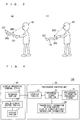
- Fig. 1 is a schematic view for describing a display processing terminal device and a photosensor-equipped unit according to a first comparative example, wherein parts (a) and (b) of Fig. 1 are views illustrating an appearance of a display processing terminal device 10, while part (c) of Fig. 1 is a view illustrating an appearance of a photosensor-equipped unit 20.
- the display processing terminal device 10 includes a display portion 11 that performs a display process with any one of plural display directions (e.g., the arrowed line AR1 illustrated in part (a) of Fig. 1 or the arrowed line AR2 illustrated in part (b) of Fig. 1 ) being specified as an upper direction of a display screen, and an interface portion 13 (not illustrated in Fig. 1 , see later-described Fig. 4 ) that can communicate with the photosensor-equipped unit 20 when the display processing terminal device 10 is connected to the photosensor-equipped unit 20.
- plural display directions e.g., the arrowed line AR1 illustrated in part (a) of Fig. 1 or the arrowed line AR2 illustrated in part (b) of Fig. 1
- an interface portion 13 not illustrated in Fig. 1 , see later-described Fig. 4
- the display processing terminal device 10 include an electronic device of a general-purpose terminal complying with an USB standard, such as a smartphone, cellular phone, PDA, game machine, and personal computer.
- the display processing terminal device 10 includes operation buttons 16 for various operations mounted in the vicinity of the display portion 11.
- the photosensor-equipped unit 20 includes an illumination photometry sensor (photosensor) 21 that receives light and acquires predetermined photometric data relating to the received light, and an interface portion 23 that can be connected to the interface portion 13 of the display processing terminal device 10.
- the photosensor-equipped unit 20 is a box-like sensor housing unit in which later-described components (see later-described Fig. 4 ) are stored, and is configured as an illumination photometry sensor unit having the illumination photometry sensor 21 mounted to the photosensor-equipped unit 20. If the photosensor-equipped unit 20 is formed into a card-like shape (thin shape) in consideration of a thickness of a commonly-used smartphone or cellular phone, the photosensor-equipped unit 20 can provide excellent portability and usability when connected.
- Fig. 2 is a schematic view for describing a photometric system 100 according to the first comparative example.
- the photometric system 100 includes the photosensor-equipped unit 20 (see part (c) of Fig. 1 ), which has mounted thereto the illumination photometry sensor 21 that receives light and acquires predetermined photometric data relating to the received light, and the display processing terminal device 10 (see parts (a) and (b) of Fig. 1 ) that includes the display portion 11 performing the display process with any one of the plural display directions being specified as the upper direction of the display screen and the interface portion 13 that can communicate with the photosensor-equipped unit 20 when the display processing terminal device 10 is connected to the photosensor-equipped unit 20.
- the photometric system 100 is configured by combining the photosensor-equipped unit 20 and the display processing terminal device 10 in such a manner that the display processing terminal device 10 and the photosensor-equipped unit 20 are connected to each other so as to enable communication. Specifically, the photometric system 100 functions as a carriageable portable illumination meter.
- Fig. 3 Part (a) of Fig. 3 illustrates the case in which the user US holds the display processing terminal device 101 at a tilt angle such that the photosensor-equipped unit 201 is located at an upper side of the display processing terminal device 101.
- a display direction (arrowed line AR3) is set such that the direction opposite to the gravitational direction is the upper direction of the display screen, and the gravitational direction is the lower direction of the display screen.
- the display direction of the screen is determined based upon the tilt angle of the body of the display processing terminal device 101, i.e., the attitude of the display processing terminal device 101. Therefore, the setting of the display direction of the arrowed line AR3 indicates that the display direction is set in a general direction in which the user US can easily view the screen, with respect to a viewing direction SR1 of the user US.
- the display direction (arrowed line AR4) is set such that the direction opposite to the gravitational direction is the upper direction of the display screen, and the gravitational direction is the lower direction of the screen.
- the display direction of the arrowed line AR4 is generally the direction having poor visibility with respect to a viewing direction SR2 of the user US.
- the screen display direction has to be appropriately changed according to the type and usage of the photosensor-equipped unit 201.
- a display processing terminal device, a photosensor-equipped unit, and a photometric system according to the present invention of the subject application are configured to present a viewing direction or holding direction by which the screen display direction is suitable for the user US who uses the display processing terminal device connected to the photosensor-equipped unit.
- Fig. 4 is a diagram illustrating an example of a basic functional configuration of the photometric system 100 according to the first comparative example.
- the photometric system 100 has a configuration formed by combining the display processing terminal device 10 and the photosensor-equipped unit 20 as described later.
- the display processing terminal device 10 in the photometric system 100 includes the display portion 11 and the interface portion 13.
- the display processing terminal device 10 also acquires transmission information relating to a screen display direction, i.e., information (the detail will be described later) referred to by the display processing terminal device 10 as screen display direction information, which is acquired from the photosensor-equipped unit 20 via the interface portion 13, from the photosensor-equipped unit 20, when the display processing terminal device 10 is connected to the photosensor-equipped unit 20.
- the transmission information may be acquired such that the display processing terminal device 10 transmits an inquiry signal and the photosensor-equipped unit 20 gives a response to this inquiry signal.
- the transmission information may be acquired such that the photosensor-equipped unit 20 transmits a signal relating to the transmission information to the display processing terminal device 10.
- the display processing terminal device 10 also includes a screen display control portion 12 that executes a display direction setting process during connection for setting a screen display direction of the display portion 11 based upon the transmission information.
- the display portion 11 is made of a liquid crystal display, and displays a result of measurement data sent from the photosensor-equipped unit 20. Alternatively, the display portion 11 may analyze data with application software in the display processing terminal device 10, and display the content according to the analyzed result.
- the screen display control portion 12 of the display processing terminal device 10 executes the display direction setting process during connection based upon the transmission information relating to the screen display direction acquired from the photosensor-equipped unit 20.
- the screen display direction of the display portion 11 in the display processing terminal device 10 can automatically be set such that the side where the photosensor-equipped unit 20 is connected becomes a desired direction. Consequently, when the user US uses the display processing terminal device 10 connected to the photosensor-equipped unit 20, the screen display control portion 12 can present the viewing direction or holding direction suitable for the user US who has no knowledge about the suitable viewing direction or the holding direction, whereby the usability for the user US is enhanced.
- the display processing terminal device 10 does not have to have a system for allowing the user US to set the viewing direction or the holding direction, whereby cost can be reduced.
- the user US does not have to set the viewing direction or the holding direction, whereby the usability is further enhanced.
- the photosensor-equipped unit 20 includes the illumination photometry sensor 21 and the interface portion 23, and further includes a transmission information holding portion 24 that holds the transmission information relating to the screen display direction of the display portion 11 as a content suitable for the illumination photometry sensor 21.
- the transmission information holding portion 24 can transmit the transmission information relating to the screen display direction of the display portion 11 in the display processing terminal device 10 to the display processing terminal device 10, and the screen display control portion 12 in the display processing terminal device 10 executes the display direction setting process during connection based upon the transmission information.
- the photosensor-equipped unit 20 also includes a peripheral circuit portion 22 that is a circuit portion for allowing the interface portion 23, the illumination photometry sensor 21, and the transmission information holding portion 24 to operate in association with one another.
- the illumination photometry sensor 21 includes a photosensor, which can measure a target illumination, as a functional component.
- the transmission information held by the transmission information holding portion 24 is set as display direction direct instruction information indicating that the side of the photosensor-equipped unit 20 becomes the upper direction (direction of the arrowed line AR5 in Fig. 5 described later) of the display screen of the display portion 11 (display processing terminal device 10).
- the photosensor-equipped unit 20 can transmit the transmission information (display direction direct instruction information) to the display processing terminal device 10, when connected to the display processing terminal device 10. Therefore, the photosensor-equipped unit 20 can set the screen display direction of the display portion 11 in the display processing terminal device 10 to the direction suitable for the illumination photometry sensor 21 by holding the transmission information suitable for the illumination photometry sensor 21 mounted to the photosensor-equipped unit 20.
- the photosensor-equipped unit 20 holds the display direction direct instruction information, instructing that the side of the photosensor-equipped unit 20 becomes the upper direction of the display screen of the display portion 11 in the display processing terminal device 10, as the transmission information. Therefore, different from the conventional display processing terminal device 101 illustrated in Fig. 3 , the photosensor-equipped unit 20 that is used as being connected to the display processing terminal device 10 can allow the user US to hold the side of the display portion 11 where the illumination photometry sensor 21 is not mounted in order to prevent the illumination photometry sensor 21 from being hidden behind the user US upon the measurement. As a result, photometric data can accurately be obtained by the illumination photometry sensor 21.
- the side where the photosensor-equipped unit 20 is mounted with the illumination photometry sensor 21 always becomes the upper direction of the display screen from the user US, even if the attitude of the display processing terminal device 10 connected to the photosensor-equipped unit 20 is changed. Therefore, the visibility is not deteriorated.
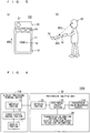
- Fig. 5 is a view for describing the photometric system 100 according to the first comparative example. Part (a) of Fig. 5 is an overall configuration of the photometric system 100, and part (b) of Fig. 5 is a view illustrating its usage example.
- the illumination photometry sensor 21 is mounted to the photosensor-equipped unit 20 in the photometric system 100, and the illumination photometry sensor 21 is arranged at the side most apart from the user US.
- the side where the photosensor-equipped unit 20 is mounted desirably becomes the upper direction of the display screen, so that information directly instructing the display direction (arrowed line AR5) is set as the transmission information (display direction direct instruction information).
- the transmission information display direction direct instruction information
- the screen display direction is automatically set to the direction based on the transmission information (display direction direct instruction information), whereby the display direction is set to the direction that the user US can easily view the screen relative to a viewing direction SR3 of the user US. Accordingly, the user US can easily recognize numerals or characters 19 (see part (a) of Fig. 5 ) relating to the measurement data displayed in the direction of the arrowed line AR5 on the display portion 11.
- the screen display direction is always automatically set, as a default, to the direction (arrowed line AR5) in which the side where the photosensor-equipped unit 20 is mounted becomes the upper direction of the display screen of the display portion 11, without depending upon the tilt angle (attitude) of the body of the display processing terminal device 10 (see Fig. 5 ).
- the display processing terminal device 10 in the photometric system 100 recognizes the transmission information (display direction direct instruction information) transmitted from the photosensor-equipped unit 20, and executes the display direction setting process during connection based upon the transmission information.
- the display processing terminal device 10 holds the transmission information suitable for the illumination photometry sensor 21 mounted to the photosensor-equipped unit 20, whereby it can automatically set the screen display direction by which the user US can easily view the screen without deteriorating the accuracy of the photometric data of the illumination photometry sensor 21. Accordingly, the accuracy of the photometric data and usability for the user US are enhanced.
- the display direction direct instruction information instructing that the side where the photosensor-equipped unit 20 is mounted becomes the upper direction of the display screen of the display portion 11 can be acquired as the transmission information. Therefore, the display processing terminal device 10 can lead the user US to hold the side of the display portion 11 where the illumination photometry sensor 21 is not mounted, in order to prevent the illumination photometry sensor 21 from being hidden behind the user US during the measurement. Consequently, the illumination photometry sensor 21 can acquire photometric data with high accuracy.
- the screen display control portion 12 desirably controls to fix the screen display direction of the display portion 11 to the direction set in the display direction setting process during connection, if the connection between the display processing terminal device 10 and the photosensor-equipped unit 20 is maintained.
- Fig. 6 is a diagram illustrating an example of a basic functional configuration of a photometric system 100A according to a second comparative example.
- the basic functional configuration of the photometric system 100A according to the second comparative example will be described with reference to Fig. 6 .
- the schematic configuration and function of the photometric system 100A according to the second comparative example are different from those of the first comparative example in that a photosensor in the second embodiment is provided as a color measuring sensor 21A, while the photosensor in the first comparative example is provided as the illumination photometry sensor 21. Therefore, a photosensor-equipped unit 20A and a display processing terminal device 10A are changed to be adapted to the color measuring sensor 21A. In other words, the color measuring sensor 21A is provided in place of the illumination photometry sensor 21, and the content of the transmission information held in the transmission information holding portion 24 is changed.
- the other configuration and function are the same as those of the photometric system 100 in the first comparative example.
- the photosensor-equipped unit 20A is configured as a color measuring sensor including a color measuring sensor 21A, a general principle and usage pattern of a color measuring sensor will schematically be described.
- the color measuring sensor includes an illumination system and a light-receiving system.
- the illumination system illuminates a surface to be measured of a subject to be measured at a predetermined angle
- the light-receiving system receives reflection light reflected from the surface to be measured by the light from the illumination system at a predetermined angle, whereby a color of the surface to be measured is measured.
- the user US is likely to use the color measuring sensor facing downward (e.g., see later-described part (b) of Fig. 7 ).
- the photosensor-equipped unit 20A sets the transmission information as display direction direct instruction information instructing that the side where the photosensor-equipped unit 20A is mounted becomes the lower direction (the direction of the arrowed line AR6 in later-described Fig. 7 ) of the display screen of the display portion 11 (display processing terminal device 10A).
- the screen display control portion 12 in the display processing terminal device 10A executes the display direction setting process during connection for setting the screen display direction of the display portion 11 based upon the transmission information (display direction direct instruction information) acquired from the photosensor-equipped unit 20A, when the display processing terminal device 10 is connected to the photosensor-equipped unit 20A.
- the photosensor-equipped unit 20A holds the display direction direct instruction information, which instructs that the side where the photosensor-equipped unit 20A is mounted becomes the lower direction of the display screen of the display portion 11 in the display processing terminal device 10A, in the transmission information holding portion 24 as the transmission information. Accordingly, when the photosensor-equipped unit 20A is used as being connected to the display processing terminal device 10A, the display portion 11 in the display processing terminal device 10A displays such that the side where the color measuring sensor 21A, which is frequently used to face downward, becomes the lower direction of the display screen. With this, the user can view the screen without having deterioration in the visibility even if the attitude of the display processing terminal device 10A is changed.
- the photosensor is the color measuring sensor 21A in the photometric system 100A. Therefore, as described above, the screen display direction by which visibility is assured when the user US uses the color measuring sensor 21A facing downward (arrowed line OB1) is the display direction of the arrowed line AR6 in which the side where the photosensor-equipped unit 20A is mounted becomes the lower direction of the display screen of the display portion 11 as illustrated in part (a) of Fig. 7 , and the transmission information is set as the display direction direct instruction information directly instructing this display direction (arrowed line AR6).
- the user US makes the measurement with the side where the photosensor-equipped unit 20A is mounted being located at the lower side of the display processing terminal device 10A (arrowed line OB1) as illustrated in part (b) of Fig.
- the display direction is automatically set to the display direction based upon the transmission information. Therefore, the display direction is set to the direction by which the user US can easily view the screen with respect to a viewing direction SR4 of the user US. Accordingly, the user US can easily recognize numerals or characters 19A displayed on the display portion 11 in the display direction of the arrowed line AR6.
- the screen display direction of the display portion 11 is automatically set, as a default, to the direction of the arrowed line AR6 opposite to the measurement direction of the arrowed line OB1 (see Fig. 7 ).
- the display direction direct instruction information instructing that the side where the photosensor-equipped unit 20A is mounted becomes the lower direction of the display screen of the display portion 11 is obtained as the transmission information, since the photosensor is the color measuring sensor 21A. Therefore, the display portion 11 executes the display process such that the side where the color measuring sensor 21A that is likely to be used to face downward is mounted becomes the lower direction of the display screen, whereby the user can view the screen without having deterioration in visibility even when the attitude is changed.
- the screen display direction of the display portion 11 in the display processing terminal device 10A can automatically be set to the direction (direction of the arrowed line AR6 in Fig. 7 ) suitable for the case where the photosensor-equipped unit 20A having the color measuring sensor is used.
- the screen display control portion 12 may employ a structure to fix the screen display direction of the display portion 11 to the direction set in the display direction setting process during connection, if the connection between the display processing terminal device 10A and the photosensor-equipped unit 20A is maintained.
- Fig. 8 is a diagram illustrating an example of a basic functional configuration of a photometric system 100B according to a first embodiment of the present invention.
- the different point in the functional configuration between the photometric system 100B according to the first embodiment and the first comparative example is that a direction determination information holding portion 14 (see Fig. 8 ) is also provided to a display processing terminal device 10B.
- the photosensor-equipped unit 20B includes a transmission information holding portion 25 that holds photosensor identification information, which can identify a type of a photosensor 21B, instead of the transmission information holding portion 24.
- the photosensor 21B may be the illumination photometry sensor 21 as in the first comparative example or the color measuring sensor 21A as in the second comparative example.
- the other configuration and function are the same as those of the photometric system 100 in the first comparative example.
- the transmission information held in the transmission information holding portion 25 includes the photosensor identification information for identifying the type (illumination photometry sensor or color measuring sensor) of the photosensor in the photosensor 21B, and is transmitted to a screen display control portion 12B via the interface portions 23 and 13 during the connection.
- the transmission information may be delivered such that a signal relating to the transmission information is transmitted to the display processing terminal device 10B from the photosensor-equipped unit 20B, or the photosensor-equipped unit 20 transmits a response to an inquiry signal transmitted from the display processing terminal device 10B and the screen display control portion 12B acquires this response.
- the screen display control portion 12B determines the content of the instruction of the display direction determination information based upon the transmission information (photosensor identification information), and executes the display direction setting process during connection.
- the direction determination information holding portion 14 holds the display direction determination information determined as described above.
- the photosensor identification information may be any information, so long as it can identify the type of the sensor of the photosensor 21B.
- a numeral or character may be used as the photosensor identification information.
- the photosensor-equipped unit 20B can be configured as the photosensor-equipped unit 20 including the illumination photometry sensor 21 in the first embodiment, as well as configured as the photosensor-equipped unit 20A including the color measuring sensor 21A in the second embodiment (see Fig. 8 ).
- the photosensor-equipped unit 20B includes the illumination photometry sensor as the photosensor 21B
- the photosensor identification information indicating that the photosensor is the illumination photometry sensor
- the screen display control portion 12B executes the display direction setting process during connection for determining the display direction determination information, which instructs that the side where the photosensor-equipped unit 20B is mounted becomes the upper direction of the display screen of the display portion 11, based upon the transmission information (photosensor identification information), and holds the display direction determination information in the direction determination information holding portion 14.
- the display control similar to the display control in the first comparative example can be executed.
- the screen display control portion 12B executes the display direction setting process during connection for determining the display direction determination information, which instructs that the side where the photosensor-equipped unit 20B is mounted becomes the lower direction of the display screen of the display portion 11, based upon the transmission information (photosensor identification information), and holds the display direction determination information in the direction determination information holding portion 14.
- the display control similar to the display control in the second comparative example can be executed.
- the screen display control portion 12B in the display processing terminal device 10B determines the display direction determination information for determining the screen display direction of the display portion 11 upon the connection to the photosensor-equipped unit 20B based upon the transmission information (photosensor identification information) held in the transmission information holding portion 25, and executes the display direction setting process during connection.
- the display direction by which the user US can easily view the screen can automatically be set, in consideration of the type of the photosensor, i.e., the illumination photometry sensor or the color measuring sensor, in the photosensor 21B in the photosensor-equipped unit 20B, without causing deterioration in accuracy of the photometric data of the photosensor 21B. Accordingly, the accuracy of the photometric data and usability for the user US are enhanced.
- the photosensor-equipped unit 20B may hold only the photosensor identification information as the transmission information, or may hold the photosensor identification information and the display direction direct instruction information as described in the comparative examples 1 and 2.
- the screen display control portion 12B may employ a structure to fix the screen display direction of the display portion 11 to the direction (instructed by the display direction determination information) set in the display direction setting process during connection, if the connection between the display processing terminal device 10B and the photosensor-equipped unit 20B is maintained, in the first embodiment.
- Fig. 9 is a diagram illustrating an example of a basic functional configuration of a photometric system 100C according to a second embodiment.
- the different point in the functional configuration between the photometric system 100C according to the second embodiment and the first embodiment is that a display direction changing portion during connection 15 (see Fig. 9 ) is also provided to the display processing terminal device 10B.
- the other configuration and function are the same as those of the photometric system 100B in the first embodiment.
- the display direction changing portion during connection 15 can change the screen display direction after the above-mentioned display direction setting process during connection to the other display direction, during the connection to the photosensor-equipped unit 20B.
- the display direction changing portion during connection 15 is provided to the display processing terminal device 10B including the direction determination information holding portion 14 according to the first embodiment.
- the display direction changing portion during connection 15 can also be provided to the display processing terminal device 10 (10A), which does not include the direction determination information holding portion 14, according to the first (second) comparative example.
- Fig. 10 is a view for describing the photometric system 100C according to the second embodiment.
- Part (a) of Fig. 10 is a view illustrating an overall configuration of the photometric system 100C
- part (b) of Fig. 10 is a view illustrating a usage example thereof. It is described that the photometric system 100C in Fig. 10 includes the photosensor-equipped unit 20B to which a color measuring sensor is mounted as the photosensor 21B.
- the direction of the arrowed line AR7 opposite to the measuring direction of the arrowed line OB2 is set to be a default as the screen display direction of the display portion 11 in the display processing terminal device 10C (see the second comparative example and Fig. 7 ).
- the display direction is the direction of the arrowed line AR7
- visibility is deteriorated with respect to a viewing direction SR5 of the user US.
- the user US can change the screen display direction to the arrowed line AR8 by giving an instruction to the display direction changing portion during connection 15 via the operation unit 16 of the display processing terminal device 10C.
- the user US can easily recognize numerals or characters 19C displayed on the display screen of the display portion 11 in the display direction of the arrowed line AR8.
- the function of the display direction changing portion during connection 15 in the photometric system 100C is effective.
- the display processing terminal device 10C further includes the display direction changing portion during connection 15 that can change the screen display direction (arrowed line AR7 in Fig. 10 ) after the display direction setting process during connection to the other display direction (arrowed line AR8 in Fig. 10 ), when the display processing terminal device 10C is connected to the photosensor-equipped unit 20B.
- the screen display direction can be changed depending upon the usage pattern, even after the display direction setting process during connection, whereby the display direction desired by the user US (arrowed line AR8 in Fig. 10 ) can be realized.
- the usability for the user US is more enhanced.
- Fig. 11 is a diagram illustrating a functional configuration of a modification of the photometric system 100C according to the second embodiment.
- the different point in the functional configuration between a photometric system 100C' and the second embodiment is that a photosensor-equipped unit 20B' does not include the transmission information holding portion 25, and a screen display control portion 12C' in a display processing terminal device 10C' is changed so as to be adapted to the above configuration.
- transmission information is not transmitted to the display processing terminal device 10C' from the photosensor-equipped unit 20B', since the transmission information holding portion 25 is not present.
- the screen display control portion 12C' determines and decides the screen display direction of the display portion 11 by setting the display direction determination information instructing a predetermined display direction during the connection to the photosensor-equipped unit 20B'. Specifically, the screen display control portion 12C' determines and holds the instruction content of the display direction determination information without depending upon the connected photosensor-equipped unit 20B', thereby executing the display direction setting process during connection.
- the display processing terminal device 10C' determines and sets the display direction, even if the transmission information according to the type of the photosensor of the photosensor 21B mounted to the photosensor-equipped unit 20B' is not transmitted to the display processing terminal device 10C'.
- the user When the determined screen display direction is different from the display direction desired by the user US, the user gives an instruction to the display direction changing portion during connection 15 by using the operation unit 16. Thus, the user US can change the display direction to the desired display direction.
- the photosensor 21B mounted to the photosensor-equipped unit 20B' in the photometric system 100C' may be either one of an illumination photometry sensor and a color measuring sensor (see Fig. 11 ).
- the photometric systems 100, 100A to 100C, and 100C' are separately described in each embodiment such that these photometric systems are individually embodied.
- these individual functions may be combined to one another, so long as they are consistent with one another.
- the photosensor-equipped unit has a function of measuring a target light intensity, and can be used in combination with a function (display device, speaker, printer, external transmission function (connection to phone, LAN, and the Internet)) of a general-purpose terminal.
Landscapes
- Engineering & Computer Science (AREA)
- Theoretical Computer Science (AREA)
- Physics & Mathematics (AREA)
- General Physics & Mathematics (AREA)
- Computer Hardware Design (AREA)
- Human Computer Interaction (AREA)
- General Engineering & Computer Science (AREA)
- Controls And Circuits For Display Device (AREA)
- Control Of Indicators Other Than Cathode Ray Tubes (AREA)
- Photometry And Measurement Of Optical Pulse Characteristics (AREA)
Claims (3)
- Dispositif de terminal de traitement d'affichage (10) qui peut être connecté à une unité équipée de photocapteur (20), qui inclut un photocapteur (21) configuré pour recevoir de la lumière et acquérir des données photométriques prédéterminées se rapportant à la lumière reçue, comprenant :une partie d'affichage (11) qui est à même d'effectuer un processus d'affichage avec l'une quelconque de multiples directions d'affichage spécifiée comme direction d'affichage (AR5) d'un écran d'affichage, ladite direction d'affichage (AR5, AR6) étant une direction telle qu'un utilisateur (US) puisse aisément observer l'écran d'affichage par rapport à une direction d'observation (SR3, SR4) de l'utilisateur ;une partie d'interface (13) qui est à même d'établir une communication avec ladite unité équipée de photocapteur (20) lorsque le dispositif de terminal de traitement d'affichage (10) est connecté à ladite unité équipée de photocapteur (20) ;une partie de commande d'affichage d'écran (12) qui est à même d'exécuter un processus de réglage de direction d'affichage au cours de la connexion pour régler ladite direction d'affichage de ladite partie d'affichage (11) sur la base d'informations de transmission se rapportant à ladite direction d'affichage acquise à partir de ladite unité équipée de photocapteur (20), lorsque le dispositif de terminal de traitement d'affichage (10) est connecté à ladite unité équipée de photocapteur (20) ; etune partie de maintien d'informations de détermination de direction (14) qui est à même de maintenir des informations de détermination de direction d'affichage pour déterminer une direction d'affichage de l'écran d'affichage de ladite partie d'affichage (11) lorsque le dispositif de terminal de traitement d'affichage (10) est connecté à ladite unité équipée de photocapteur (20), dans lequellesdites informations de transmission incluent des informations d'identification de photocapteur pour identifier un type dudit photocapteur (21), etladite partie de commande d'affichage d'écran (12) est à même de déterminer une teneur en instructions desdites informations de détermination de direction d'affichage sur la base desdites informations d'identification du photocapteur et d'exécuter ledit processus de réglage de direction d'affichage au cours de la connexion,caractérisé en ce que ladite partie de commande d'affichage d'écran (12) est adaptée pour,lorsque les informations d'identification du photocapteur indiquent que le photocapteur (21) est un capteur de photométrie d'éclairage, déterminer que la teneur en instructions desdites informations de détermination de direction d'affichage instruit qu'un côté du dispositif de terminal de traitement d'affichage (10) où l'unité équipée de photocapteur (20) est connectée, devient une direction supérieure (AR5) de l'écran d'affichage de la partie d'affichage (11), etlorsque les informations d'identification du photocapteur indiquent que le photocapteur (21) est un capteur de mesure de couleur, déterminer que la teneur en instructions desdites informations de détermination de direction d'affichage instruit qu'un côté du dispositif de terminal de traitement d'affichage (10) où l'unité équipée de photocapteur (20) est connectée devient une direction inférieure (AR6) de l'écran d'affichage de la partie d'affichage (11).
- Dispositif de terminal de traitement d'affichage (10) selon la revendication 1, comprenant en outre :
une partie de changement de direction d'affichage au cours de la connexion (15) qui est à même de changer ladite direction d'affichage après ledit processus de réglage de direction d'affichage au cours de la connexion en une autre direction d'affichage, lorsque le dispositif de terminal de traitement d'affichage (10) est connecté à ladite unité équipée de photocapteur. - Système photométrique comprenant le dispositif de terminal de traitement d'affichage (10) selon l'une quelconque des revendications 1 - 2 et l'unité équipée de photocapteur (20) qui inclut le photocapteur (21) et peut être connectée au dispositif de terminal de traitement d'affichage (10), l'unité équipée de photocapteur (20) comprenant :une partie de maintien d'informations de transmission (24) qui est à même de maintenir les informations de transmission, dans lequella partie de maintien d'informations de transmission (24) est à même de transmettre lesdites informations de transmission audit dispositif de terminal de traitement d'affichage (10), lorsque l'unité équipée de photocapteur (20) est connectée audit dispositif de terminal de traitement d'affichage (10).
Applications Claiming Priority (2)
| Application Number | Priority Date | Filing Date | Title |
|---|---|---|---|
| JP2012070575 | 2012-03-27 | ||
| PCT/JP2013/053954 WO2013145938A1 (fr) | 2012-03-27 | 2013-02-19 | Dispositif de terminal de traitement d'affichage, unité équipée d'un photocapteur et système photométrique |
Publications (3)
| Publication Number | Publication Date |
|---|---|
| EP2833353A1 EP2833353A1 (fr) | 2015-02-04 |
| EP2833353A4 EP2833353A4 (fr) | 2015-08-26 |
| EP2833353B1 true EP2833353B1 (fr) | 2018-05-02 |
Family
ID=49259220
Family Applications (1)
| Application Number | Title | Priority Date | Filing Date |
|---|---|---|---|
| EP13767319.0A Active EP2833353B1 (fr) | 2012-03-27 | 2013-02-19 | Dispositif de terminal de traitement d'affichage, unité équipée d'un photocapteur et système photométrique |
Country Status (4)
| Country | Link |
|---|---|
| US (1) | US9965872B2 (fr) |
| EP (1) | EP2833353B1 (fr) |
| JP (1) | JP5440746B1 (fr) |
| WO (1) | WO2013145938A1 (fr) |
Families Citing this family (2)
| Publication number | Priority date | Publication date | Assignee | Title |
|---|---|---|---|---|
| WO2015199806A1 (fr) * | 2014-06-24 | 2015-12-30 | Google Inc. | Commande de la luminosité d'un dispositif d'affichage à distance |
| CN113220139B (zh) * | 2019-07-30 | 2022-08-02 | 荣耀终端有限公司 | 控制大屏设备显示的方法、移动终端及第一系统 |
Citations (6)
| Publication number | Priority date | Publication date | Assignee | Title |
|---|---|---|---|---|
| JPH10198627A (ja) * | 1996-12-28 | 1998-07-31 | Casio Comput Co Ltd | データ処理装置およびそのプログラム記録媒体 |
| US20020135566A1 (en) * | 2001-03-21 | 2002-09-26 | Siltek Corporation | Apparatus, method, and system for change of display direction |
| US20070035647A1 (en) * | 2005-08-10 | 2007-02-15 | Fuji Photo Film Co., Ltd. | Imaging device unit and camera system |
| EP1763226A2 (fr) * | 2005-09-08 | 2007-03-14 | Konica Minolta Opto, Inc. | Dispositif de prise de vue |
| US20090193156A1 (en) * | 2008-01-28 | 2009-07-30 | Sony Nec Optiarc Inc. | Peripheral device, method of operating peripheral device, host device, method of operating host device, and electronic device system |
| WO2011129136A1 (fr) * | 2010-04-15 | 2011-10-20 | シャープ株式会社 | Dispositif d'affichage et système de basculement de la direction d'affichage |
Family Cites Families (10)
| Publication number | Priority date | Publication date | Assignee | Title |
|---|---|---|---|---|
| JPH11239670A (ja) * | 1998-02-25 | 1999-09-07 | Sony Corp | 携帯用電子機器 |
| US20020109664A1 (en) * | 1999-02-19 | 2002-08-15 | Masaki Shimada | Display apparatus and an image processing apparatus |
| JP3692869B2 (ja) * | 1999-11-18 | 2005-09-07 | 株式会社日立製作所 | 情報処理装置 |
| JP2005340918A (ja) * | 2004-05-24 | 2005-12-08 | Seiko Epson Corp | 画像表示装置、画像供給装置、画像表示システムおよび画像表示方法 |
| JP4350740B2 (ja) * | 2006-12-05 | 2009-10-21 | レノボ・シンガポール・プライベート・リミテッド | 携帯式電子機器、画面の表示方向の変更方法、プログラムおよび記憶媒体 |
| JP2009141484A (ja) * | 2007-12-04 | 2009-06-25 | Canon Inc | 画像処理装置、情報処理装置、それらの制御方法、プログラム |
| KR101497582B1 (ko) * | 2008-12-24 | 2015-03-02 | 삼성디스플레이 주식회사 | 표시 장치 |
| JP4752922B2 (ja) * | 2009-01-30 | 2011-08-17 | ソニー株式会社 | 画像表示装置および電子装置 |
| JP4818454B1 (ja) * | 2010-08-27 | 2011-11-16 | 株式会社東芝 | 表示装置、及び表示方法 |
| EP2613517B1 (fr) * | 2012-01-06 | 2015-05-06 | Canon Kabushiki Kaisha | Dispositif d'éclairage capable d'avoir un accessoire optique fixé à l'avant de la section d'émission de lumière de celui-ci, système de prise d'image, support de film, dispositif et procédé de commande d'émission de lumière |
-
2013
- 2013-02-19 US US14/389,342 patent/US9965872B2/en active Active
- 2013-02-19 EP EP13767319.0A patent/EP2833353B1/fr active Active
- 2013-02-19 JP JP2013539060A patent/JP5440746B1/ja active Active
- 2013-02-19 WO PCT/JP2013/053954 patent/WO2013145938A1/fr not_active Ceased
Patent Citations (7)
| Publication number | Priority date | Publication date | Assignee | Title |
|---|---|---|---|---|
| JPH10198627A (ja) * | 1996-12-28 | 1998-07-31 | Casio Comput Co Ltd | データ処理装置およびそのプログラム記録媒体 |
| US20020135566A1 (en) * | 2001-03-21 | 2002-09-26 | Siltek Corporation | Apparatus, method, and system for change of display direction |
| US20070035647A1 (en) * | 2005-08-10 | 2007-02-15 | Fuji Photo Film Co., Ltd. | Imaging device unit and camera system |
| EP1763226A2 (fr) * | 2005-09-08 | 2007-03-14 | Konica Minolta Opto, Inc. | Dispositif de prise de vue |
| US20090193156A1 (en) * | 2008-01-28 | 2009-07-30 | Sony Nec Optiarc Inc. | Peripheral device, method of operating peripheral device, host device, method of operating host device, and electronic device system |
| WO2011129136A1 (fr) * | 2010-04-15 | 2011-10-20 | シャープ株式会社 | Dispositif d'affichage et système de basculement de la direction d'affichage |
| US20130027356A1 (en) * | 2010-04-15 | 2013-01-31 | Sharp Kabushiki Kaisha | Display device and display direction switching system |
Also Published As
| Publication number | Publication date |
|---|---|
| EP2833353A1 (fr) | 2015-02-04 |
| JPWO2013145938A1 (ja) | 2015-12-10 |
| US9965872B2 (en) | 2018-05-08 |
| EP2833353A4 (fr) | 2015-08-26 |
| US20150109317A1 (en) | 2015-04-23 |
| JP5440746B1 (ja) | 2014-03-12 |
| WO2013145938A1 (fr) | 2013-10-03 |
Similar Documents
| Publication | Publication Date | Title |
|---|---|---|
| US10867450B2 (en) | Augmented reality lighting effects | |
| US20200374508A1 (en) | Display apparatus and method for controlling display apparatus | |
| CN111034161B (zh) | 包括使用显示面板的结构的天线的电子装置 | |
| US11017201B2 (en) | Electronic device for recognizing fingerprint using display | |
| KR20200129584A (ko) | 복수의 카메라들을 이용한 촬영 제어 방법 및 폴더블 장치 | |
| KR102502583B1 (ko) | 복수의 이미지 센서들의 동기화 제어 방법 및 이를 구현한 전자 장치 | |
| US8976111B2 (en) | Electronic device and method for operating electronic device | |
| CN107295239A (zh) | 一种摄像头组件及电子设备 | |
| CN103165069A (zh) | 显示控制设备和显示控制设备的控制方法 | |
| US20160187661A1 (en) | Electronic apparatus, display device, and control method for electronic apparatus | |
| JP6966953B2 (ja) | 撮像システム、撮像方法及びプログラム | |
| US20210200284A1 (en) | Image display device, power supply system, and power supply method for image display device | |
| EP2833353B1 (fr) | Dispositif de terminal de traitement d'affichage, unité équipée d'un photocapteur et système photométrique | |
| EP1336916A2 (fr) | Dispositif de mesure de position et la direction, et procédé de traitement d'informations | |
| JP6609920B2 (ja) | 表示装置、及び、表示装置の制御方法 | |
| KR102600509B1 (ko) | 전자 장치 및 그 촬영 관련 정보 안내 방법 | |
| US11889181B2 (en) | Electronic device having plurality of lenses where the device changes a visual object corresponding to a recommended lens | |
| CN107566555B (zh) | 投影手机 | |
| EP4022884B1 (fr) | Dispositif électronique et procédé pour corriger une image dans une commutation de caméra | |
| US9494423B2 (en) | Photometric apparatus and measurement control program | |
| US10345919B2 (en) | Accessory between display and keyboard | |
| CN113824902B (zh) | 红外摄像机系统时延确定方法、装置、系统、设备及介质 | |
| EP2618325A1 (fr) | Terminal de traitement d'informations et dispositif de commande d'écran et procédé associé | |
| KR20190048944A (ko) | 지문 영상 획득 방법 및 이를 지원하는 전자 장치 | |
| JP5157631B2 (ja) | カメラシステム |
Legal Events
| Date | Code | Title | Description |
|---|---|---|---|
| PUAI | Public reference made under article 153(3) epc to a published international application that has entered the european phase |
Free format text: ORIGINAL CODE: 0009012 |
|
| 17P | Request for examination filed |
Effective date: 20140926 |
|
| AK | Designated contracting states |
Kind code of ref document: A1 Designated state(s): AL AT BE BG CH CY CZ DE DK EE ES FI FR GB GR HR HU IE IS IT LI LT LU LV MC MK MT NL NO PL PT RO RS SE SI SK SM TR |
|
| AX | Request for extension of the european patent |
Extension state: BA ME |
|
| DAX | Request for extension of the european patent (deleted) | ||
| RA4 | Supplementary search report drawn up and despatched (corrected) |
Effective date: 20150724 |
|
| RIC1 | Information provided on ipc code assigned before grant |
Ipc: G09G 5/36 20060101ALI20150720BHEP Ipc: G09G 5/00 20060101AFI20150720BHEP |
|
| 17Q | First examination report despatched |
Effective date: 20160614 |
|
| GRAP | Despatch of communication of intention to grant a patent |
Free format text: ORIGINAL CODE: EPIDOSNIGR1 |
|
| STAA | Information on the status of an ep patent application or granted ep patent |
Free format text: STATUS: GRANT OF PATENT IS INTENDED |
|
| INTG | Intention to grant announced |
Effective date: 20180102 |
|
| GRAS | Grant fee paid |
Free format text: ORIGINAL CODE: EPIDOSNIGR3 |
|
| GRAA | (expected) grant |
Free format text: ORIGINAL CODE: 0009210 |
|
| STAA | Information on the status of an ep patent application or granted ep patent |
Free format text: STATUS: THE PATENT HAS BEEN GRANTED |
|
| AK | Designated contracting states |
Kind code of ref document: B1 Designated state(s): AL AT BE BG CH CY CZ DE DK EE ES FI FR GB GR HR HU IE IS IT LI LT LU LV MC MK MT NL NO PL PT RO RS SE SI SK SM TR |
|
| REG | Reference to a national code |
Ref country code: GB Ref legal event code: FG4D |
|
| REG | Reference to a national code |
Ref country code: CH Ref legal event code: EP Ref country code: AT Ref legal event code: REF Ref document number: 996070 Country of ref document: AT Kind code of ref document: T Effective date: 20180515 |
|
| REG | Reference to a national code |
Ref country code: DE Ref legal event code: R096 Ref document number: 602013036935 Country of ref document: DE Ref country code: IE Ref legal event code: FG4D |
|
| REG | Reference to a national code |
Ref country code: NL Ref legal event code: MP Effective date: 20180502 |
|
| REG | Reference to a national code |
Ref country code: LT Ref legal event code: MG4D |
|
| PG25 | Lapsed in a contracting state [announced via postgrant information from national office to epo] |
Ref country code: FI Free format text: LAPSE BECAUSE OF FAILURE TO SUBMIT A TRANSLATION OF THE DESCRIPTION OR TO PAY THE FEE WITHIN THE PRESCRIBED TIME-LIMIT Effective date: 20180502 Ref country code: NO Free format text: LAPSE BECAUSE OF FAILURE TO SUBMIT A TRANSLATION OF THE DESCRIPTION OR TO PAY THE FEE WITHIN THE PRESCRIBED TIME-LIMIT Effective date: 20180802 Ref country code: BG Free format text: LAPSE BECAUSE OF FAILURE TO SUBMIT A TRANSLATION OF THE DESCRIPTION OR TO PAY THE FEE WITHIN THE PRESCRIBED TIME-LIMIT Effective date: 20180802 Ref country code: ES Free format text: LAPSE BECAUSE OF FAILURE TO SUBMIT A TRANSLATION OF THE DESCRIPTION OR TO PAY THE FEE WITHIN THE PRESCRIBED TIME-LIMIT Effective date: 20180502 Ref country code: SE Free format text: LAPSE BECAUSE OF FAILURE TO SUBMIT A TRANSLATION OF THE DESCRIPTION OR TO PAY THE FEE WITHIN THE PRESCRIBED TIME-LIMIT Effective date: 20180502 Ref country code: LT Free format text: LAPSE BECAUSE OF FAILURE TO SUBMIT A TRANSLATION OF THE DESCRIPTION OR TO PAY THE FEE WITHIN THE PRESCRIBED TIME-LIMIT Effective date: 20180502 |
|
| PG25 | Lapsed in a contracting state [announced via postgrant information from national office to epo] |
Ref country code: LV Free format text: LAPSE BECAUSE OF FAILURE TO SUBMIT A TRANSLATION OF THE DESCRIPTION OR TO PAY THE FEE WITHIN THE PRESCRIBED TIME-LIMIT Effective date: 20180502 Ref country code: NL Free format text: LAPSE BECAUSE OF FAILURE TO SUBMIT A TRANSLATION OF THE DESCRIPTION OR TO PAY THE FEE WITHIN THE PRESCRIBED TIME-LIMIT Effective date: 20180502 Ref country code: GR Free format text: LAPSE BECAUSE OF FAILURE TO SUBMIT A TRANSLATION OF THE DESCRIPTION OR TO PAY THE FEE WITHIN THE PRESCRIBED TIME-LIMIT Effective date: 20180803 Ref country code: HR Free format text: LAPSE BECAUSE OF FAILURE TO SUBMIT A TRANSLATION OF THE DESCRIPTION OR TO PAY THE FEE WITHIN THE PRESCRIBED TIME-LIMIT Effective date: 20180502 Ref country code: RS Free format text: LAPSE BECAUSE OF FAILURE TO SUBMIT A TRANSLATION OF THE DESCRIPTION OR TO PAY THE FEE WITHIN THE PRESCRIBED TIME-LIMIT Effective date: 20180502 |
|
| REG | Reference to a national code |
Ref country code: AT Ref legal event code: MK05 Ref document number: 996070 Country of ref document: AT Kind code of ref document: T Effective date: 20180502 |
|
| PG25 | Lapsed in a contracting state [announced via postgrant information from national office to epo] |
Ref country code: EE Free format text: LAPSE BECAUSE OF FAILURE TO SUBMIT A TRANSLATION OF THE DESCRIPTION OR TO PAY THE FEE WITHIN THE PRESCRIBED TIME-LIMIT Effective date: 20180502 Ref country code: DK Free format text: LAPSE BECAUSE OF FAILURE TO SUBMIT A TRANSLATION OF THE DESCRIPTION OR TO PAY THE FEE WITHIN THE PRESCRIBED TIME-LIMIT Effective date: 20180502 Ref country code: AT Free format text: LAPSE BECAUSE OF FAILURE TO SUBMIT A TRANSLATION OF THE DESCRIPTION OR TO PAY THE FEE WITHIN THE PRESCRIBED TIME-LIMIT Effective date: 20180502 Ref country code: PL Free format text: LAPSE BECAUSE OF FAILURE TO SUBMIT A TRANSLATION OF THE DESCRIPTION OR TO PAY THE FEE WITHIN THE PRESCRIBED TIME-LIMIT Effective date: 20180502 Ref country code: CZ Free format text: LAPSE BECAUSE OF FAILURE TO SUBMIT A TRANSLATION OF THE DESCRIPTION OR TO PAY THE FEE WITHIN THE PRESCRIBED TIME-LIMIT Effective date: 20180502 Ref country code: RO Free format text: LAPSE BECAUSE OF FAILURE TO SUBMIT A TRANSLATION OF THE DESCRIPTION OR TO PAY THE FEE WITHIN THE PRESCRIBED TIME-LIMIT Effective date: 20180502 Ref country code: SK Free format text: LAPSE BECAUSE OF FAILURE TO SUBMIT A TRANSLATION OF THE DESCRIPTION OR TO PAY THE FEE WITHIN THE PRESCRIBED TIME-LIMIT Effective date: 20180502 |
|
| REG | Reference to a national code |
Ref country code: DE Ref legal event code: R097 Ref document number: 602013036935 Country of ref document: DE |
|
| PG25 | Lapsed in a contracting state [announced via postgrant information from national office to epo] |
Ref country code: IT Free format text: LAPSE BECAUSE OF FAILURE TO SUBMIT A TRANSLATION OF THE DESCRIPTION OR TO PAY THE FEE WITHIN THE PRESCRIBED TIME-LIMIT Effective date: 20180502 Ref country code: SM Free format text: LAPSE BECAUSE OF FAILURE TO SUBMIT A TRANSLATION OF THE DESCRIPTION OR TO PAY THE FEE WITHIN THE PRESCRIBED TIME-LIMIT Effective date: 20180502 |
|
| PLBE | No opposition filed within time limit |
Free format text: ORIGINAL CODE: 0009261 |
|
| STAA | Information on the status of an ep patent application or granted ep patent |
Free format text: STATUS: NO OPPOSITION FILED WITHIN TIME LIMIT |
|
| 26N | No opposition filed |
Effective date: 20190205 |
|
| PG25 | Lapsed in a contracting state [announced via postgrant information from national office to epo] |
Ref country code: SI Free format text: LAPSE BECAUSE OF FAILURE TO SUBMIT A TRANSLATION OF THE DESCRIPTION OR TO PAY THE FEE WITHIN THE PRESCRIBED TIME-LIMIT Effective date: 20180502 |
|
| REG | Reference to a national code |
Ref country code: CH Ref legal event code: PL |
|
| PG25 | Lapsed in a contracting state [announced via postgrant information from national office to epo] |
Ref country code: LU Free format text: LAPSE BECAUSE OF NON-PAYMENT OF DUE FEES Effective date: 20190219 Ref country code: MC Free format text: LAPSE BECAUSE OF FAILURE TO SUBMIT A TRANSLATION OF THE DESCRIPTION OR TO PAY THE FEE WITHIN THE PRESCRIBED TIME-LIMIT Effective date: 20180502 |
|
| REG | Reference to a national code |
Ref country code: BE Ref legal event code: MM Effective date: 20190228 |
|
| REG | Reference to a national code |
Ref country code: IE Ref legal event code: MM4A |
|
| PG25 | Lapsed in a contracting state [announced via postgrant information from national office to epo] |
Ref country code: AL Free format text: LAPSE BECAUSE OF FAILURE TO SUBMIT A TRANSLATION OF THE DESCRIPTION OR TO PAY THE FEE WITHIN THE PRESCRIBED TIME-LIMIT Effective date: 20180502 |
|
| PG25 | Lapsed in a contracting state [announced via postgrant information from national office to epo] |
Ref country code: LI Free format text: LAPSE BECAUSE OF NON-PAYMENT OF DUE FEES Effective date: 20190228 Ref country code: CH Free format text: LAPSE BECAUSE OF NON-PAYMENT OF DUE FEES Effective date: 20190228 |
|
| PG25 | Lapsed in a contracting state [announced via postgrant information from national office to epo] |
Ref country code: IE Free format text: LAPSE BECAUSE OF NON-PAYMENT OF DUE FEES Effective date: 20190219 |
|
| PG25 | Lapsed in a contracting state [announced via postgrant information from national office to epo] |
Ref country code: FR Free format text: LAPSE BECAUSE OF NON-PAYMENT OF DUE FEES Effective date: 20190228 Ref country code: BE Free format text: LAPSE BECAUSE OF NON-PAYMENT OF DUE FEES Effective date: 20190228 |
|
| PG25 | Lapsed in a contracting state [announced via postgrant information from national office to epo] |
Ref country code: TR Free format text: LAPSE BECAUSE OF FAILURE TO SUBMIT A TRANSLATION OF THE DESCRIPTION OR TO PAY THE FEE WITHIN THE PRESCRIBED TIME-LIMIT Effective date: 20180502 |
|
| PG25 | Lapsed in a contracting state [announced via postgrant information from national office to epo] |
Ref country code: PT Free format text: LAPSE BECAUSE OF FAILURE TO SUBMIT A TRANSLATION OF THE DESCRIPTION OR TO PAY THE FEE WITHIN THE PRESCRIBED TIME-LIMIT Effective date: 20180903 Ref country code: MT Free format text: LAPSE BECAUSE OF NON-PAYMENT OF DUE FEES Effective date: 20190219 |
|
| PG25 | Lapsed in a contracting state [announced via postgrant information from national office to epo] |
Ref country code: CY Free format text: LAPSE BECAUSE OF FAILURE TO SUBMIT A TRANSLATION OF THE DESCRIPTION OR TO PAY THE FEE WITHIN THE PRESCRIBED TIME-LIMIT Effective date: 20180502 |
|
| PG25 | Lapsed in a contracting state [announced via postgrant information from national office to epo] |
Ref country code: IS Free format text: LAPSE BECAUSE OF FAILURE TO SUBMIT A TRANSLATION OF THE DESCRIPTION OR TO PAY THE FEE WITHIN THE PRESCRIBED TIME-LIMIT Effective date: 20180902 |
|
| PG25 | Lapsed in a contracting state [announced via postgrant information from national office to epo] |
Ref country code: HU Free format text: LAPSE BECAUSE OF FAILURE TO SUBMIT A TRANSLATION OF THE DESCRIPTION OR TO PAY THE FEE WITHIN THE PRESCRIBED TIME-LIMIT; INVALID AB INITIO Effective date: 20130219 |
|
| PG25 | Lapsed in a contracting state [announced via postgrant information from national office to epo] |
Ref country code: MK Free format text: LAPSE BECAUSE OF FAILURE TO SUBMIT A TRANSLATION OF THE DESCRIPTION OR TO PAY THE FEE WITHIN THE PRESCRIBED TIME-LIMIT Effective date: 20180502 |
|
| P01 | Opt-out of the competence of the unified patent court (upc) registered |
Effective date: 20230510 |
|
| PGFP | Annual fee paid to national office [announced via postgrant information from national office to epo] |
Ref country code: GB Payment date: 20260106 Year of fee payment: 14 |
|
| PGFP | Annual fee paid to national office [announced via postgrant information from national office to epo] |
Ref country code: DE Payment date: 20251224 Year of fee payment: 14 |