EP2833433A1 - Sammelschienenbefestigungsvorrichtung und sammelschienenbefestigungsverfahren - Google Patents
Sammelschienenbefestigungsvorrichtung und sammelschienenbefestigungsverfahren Download PDFInfo
- Publication number
- EP2833433A1 EP2833433A1 EP13768205.0A EP13768205A EP2833433A1 EP 2833433 A1 EP2833433 A1 EP 2833433A1 EP 13768205 A EP13768205 A EP 13768205A EP 2833433 A1 EP2833433 A1 EP 2833433A1
- Authority
- EP
- European Patent Office
- Prior art keywords
- bus bar
- pallet
- battery
- positioning part
- relative
- Prior art date
- Legal status (The legal status is an assumption and is not a legal conclusion. Google has not performed a legal analysis and makes no representation as to the accuracy of the status listed.)
- Granted
Links
Images



Classifications
-
- H—ELECTRICITY
- H01—ELECTRIC ELEMENTS
- H01M—PROCESSES OR MEANS, e.g. BATTERIES, FOR THE DIRECT CONVERSION OF CHEMICAL ENERGY INTO ELECTRICAL ENERGY
- H01M10/00—Secondary cells; Manufacture thereof
- H01M10/04—Construction or manufacture in general
- H01M10/0404—Machines for assembling batteries
-
- H—ELECTRICITY
- H01—ELECTRIC ELEMENTS
- H01M—PROCESSES OR MEANS, e.g. BATTERIES, FOR THE DIRECT CONVERSION OF CHEMICAL ENERGY INTO ELECTRICAL ENERGY
- H01M50/00—Constructional details or processes of manufacture of the non-active parts of electrochemical cells other than fuel cells, e.g. hybrid cells
- H01M50/20—Mountings; Secondary casings or frames; Racks, modules or packs; Suspension devices; Shock absorbers; Transport or carrying devices; Holders
- H01M50/204—Racks, modules or packs for multiple batteries or multiple cells
- H01M50/207—Racks, modules or packs for multiple batteries or multiple cells characterised by their shape
- H01M50/211—Racks, modules or packs for multiple batteries or multiple cells characterised by their shape adapted for pouch cells
-
- H—ELECTRICITY
- H01—ELECTRIC ELEMENTS
- H01M—PROCESSES OR MEANS, e.g. BATTERIES, FOR THE DIRECT CONVERSION OF CHEMICAL ENERGY INTO ELECTRICAL ENERGY
- H01M50/00—Constructional details or processes of manufacture of the non-active parts of electrochemical cells other than fuel cells, e.g. hybrid cells
- H01M50/20—Mountings; Secondary casings or frames; Racks, modules or packs; Suspension devices; Shock absorbers; Transport or carrying devices; Holders
- H01M50/289—Mountings; Secondary casings or frames; Racks, modules or packs; Suspension devices; Shock absorbers; Transport or carrying devices; Holders characterised by spacing elements or positioning means within frames, racks or packs
- H01M50/291—Mountings; Secondary casings or frames; Racks, modules or packs; Suspension devices; Shock absorbers; Transport or carrying devices; Holders characterised by spacing elements or positioning means within frames, racks or packs characterised by their shape
-
- H—ELECTRICITY
- H01—ELECTRIC ELEMENTS
- H01M—PROCESSES OR MEANS, e.g. BATTERIES, FOR THE DIRECT CONVERSION OF CHEMICAL ENERGY INTO ELECTRICAL ENERGY
- H01M50/00—Constructional details or processes of manufacture of the non-active parts of electrochemical cells other than fuel cells, e.g. hybrid cells
- H01M50/50—Current conducting connections for cells or batteries
- H01M50/502—Interconnectors for connecting terminals of adjacent batteries; Interconnectors for connecting cells outside a battery casing
- H01M50/503—Interconnectors for connecting terminals of adjacent batteries; Interconnectors for connecting cells outside a battery casing characterised by the shape of the interconnectors
-
- Y—GENERAL TAGGING OF NEW TECHNOLOGICAL DEVELOPMENTS; GENERAL TAGGING OF CROSS-SECTIONAL TECHNOLOGIES SPANNING OVER SEVERAL SECTIONS OF THE IPC; TECHNICAL SUBJECTS COVERED BY FORMER USPC CROSS-REFERENCE ART COLLECTIONS [XRACs] AND DIGESTS
- Y02—TECHNOLOGIES OR APPLICATIONS FOR MITIGATION OR ADAPTATION AGAINST CLIMATE CHANGE
- Y02E—REDUCTION OF GREENHOUSE GAS [GHG] EMISSIONS, RELATED TO ENERGY GENERATION, TRANSMISSION OR DISTRIBUTION
- Y02E60/00—Enabling technologies; Technologies with a potential or indirect contribution to GHG emissions mitigation
- Y02E60/10—Energy storage using batteries
-
- Y—GENERAL TAGGING OF NEW TECHNOLOGICAL DEVELOPMENTS; GENERAL TAGGING OF CROSS-SECTIONAL TECHNOLOGIES SPANNING OVER SEVERAL SECTIONS OF THE IPC; TECHNICAL SUBJECTS COVERED BY FORMER USPC CROSS-REFERENCE ART COLLECTIONS [XRACs] AND DIGESTS
- Y02—TECHNOLOGIES OR APPLICATIONS FOR MITIGATION OR ADAPTATION AGAINST CLIMATE CHANGE
- Y02P—CLIMATE CHANGE MITIGATION TECHNOLOGIES IN THE PRODUCTION OR PROCESSING OF GOODS
- Y02P70/00—Climate change mitigation technologies in the production process for final industrial or consumer products
- Y02P70/50—Manufacturing or production processes characterised by the final manufactured product
-
- Y—GENERAL TAGGING OF NEW TECHNOLOGICAL DEVELOPMENTS; GENERAL TAGGING OF CROSS-SECTIONAL TECHNOLOGIES SPANNING OVER SEVERAL SECTIONS OF THE IPC; TECHNICAL SUBJECTS COVERED BY FORMER USPC CROSS-REFERENCE ART COLLECTIONS [XRACs] AND DIGESTS
- Y10—TECHNICAL SUBJECTS COVERED BY FORMER USPC
- Y10T—TECHNICAL SUBJECTS COVERED BY FORMER US CLASSIFICATION
- Y10T29/00—Metal working
- Y10T29/49—Method of mechanical manufacture
- Y10T29/49002—Electrical device making
- Y10T29/49108—Electric battery cell making
-
- Y—GENERAL TAGGING OF NEW TECHNOLOGICAL DEVELOPMENTS; GENERAL TAGGING OF CROSS-SECTIONAL TECHNOLOGIES SPANNING OVER SEVERAL SECTIONS OF THE IPC; TECHNICAL SUBJECTS COVERED BY FORMER USPC CROSS-REFERENCE ART COLLECTIONS [XRACs] AND DIGESTS
- Y10—TECHNICAL SUBJECTS COVERED BY FORMER USPC
- Y10T—TECHNICAL SUBJECTS COVERED BY FORMER US CLASSIFICATION
- Y10T29/00—Metal working
- Y10T29/53—Means to assemble or disassemble
- Y10T29/5313—Means to assemble electrical device
- Y10T29/53135—Storage cell or battery
Definitions
- the present invention relates to a bus bar attachment device and a bus bar attachment method applied to a battery.
- Patent Document 1 discloses a battery module in which a plurality of flat batteries are electrically connected in series or in parallel. A bus bar for guiding current to the electrode terminals of the battery module is connected to electrode tabs led out from the flat batteries.
- Patent Document 1 Japanese Laid-Open Patent Application No. 2009-231267
- the bus bar When a bus bar is attached to electrode tabs, the bus bar must be positioned relative to the electrode tabs with high precision.
- the position of the bus bar relative to the electrode tabs can be set with high precision by equipment such as a high-precision robot.
- equipment such as a high-precision robot
- the actuating speed of the equipment such as a robot must be comparatively low.
- Equipment such as a high-precision robot is also comparatively high in cost. Therefore, the work of attaching the bus bar to the battery is inhibited from being done faster and being made less expensive, and it is consequently difficult to make the manufacturing of the battery more efficient.
- the present invention was devised in order to resolve the problems described above, and an object of the invention is to provide a bus bar attachment device and a bus bar attachment method whereby the work of attaching the bus bar to the battery can be done faster and made less expensive, and the bus bar can be positioned relative to the battery with high precision.
- a bus bar attachment device of the present invention comprises[[:]] a pallet on which is placed a battery from which an electrode tab is led out; a battery positioning part for setting the position of the battery relative to the pallet, the battery positioning part being provided to the pallet; and a bus bar positioning part for setting the position, relative to the pallet, of a bus bar electrically connected to the electrode tab, the bus bar positioning part being provided to the pallet and having two adjacent wall surfaces against which two adjacent surfaces in the bus bar hit.
- the bus bar attachment device further comprises a bus bar supply part for supplying the bus bar onto the pallet, and a pressing part for causing the two adjacent surfaces in the bus bar supplied by the bus bar supply part to hit against the two adjacent wall surfaces in the bus bar positioning part of the pallet.
- the bus bar is supplied by the bus bar supply part to a position where the two surfaces come to face the two wall surfaces in the bus bar positioning part, and the two surfaces are made by the pressing part to hit against the two wall surfaces in the bus bar positioning part to set the position of the bus bar relative to the battery.
- a bus bar attachment method of the present invention comprises a placement step for placing, on a pallet, a battery from which an electrode tab is led out with the position relative to the pallet having been set, a supply step for supplying a bus bar, which is electrically connected to the electrode tab, to a position where two adjacent surfaces in the bus bar come to face two adjacent wall surfaces in a bus bar positioning part provided to the pallet for setting the position of the bus bar relative to the pallet.
- the bus bar attachment method further comprises a positioning step for causing the two adjacent surfaces in the supplied bus bar to hit against the two adjacent wall surfaces in the bus bar positioning part to set the position of the bus bar relative to the battery.
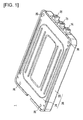
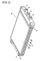
- the battery module 1 can be used separately; for example, an assembled battery suitable for the desired current, voltage, and capacity can be formed by linking a plurality of battery modules 1 in series or in parallel.
- the case 20 has a lower case 22 having a substantially triangular box shape, and an upper case 24 having a lid.
- the edge of the upper case 24 is connected to the peripheral wall edge of the lower case 22 by crimping, and the lower case 22 and the upper case 24 are formed from comparatively thin steel plates or aluminum plates.
- the lower case 22 and the upper case 24 have through-holes 26.
- the through-holes 26 are disposed in four locations in the corners, and are used in order to insert through-bolts (not shown) for stacking a plurality of battery modules 1 together to form an assembled battery.
- the symbols 31 and 32 are output terminals disposed so as to protrude from openings in the front surface of the lower case 22.
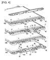
- the cell unit 30 has a stacked assembly 33 in which a plurality of flat batteries 10 are electrically connected and stacked, and a plurality of spacers 40, 90 for supporting the batteries.
- An electrically insulating resin material can be used for the spacers 40, 90.
- the spacers 40 are disposed on the front surface side of the stacked assembly 33, and the spacers 90 are disposed on the rear surface side of the stacked assembly 33.
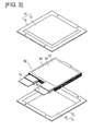
- the flat batteries 10 are lithium ion secondary batteries, each including, for example, a stacked electrode assembly 50 stored together with an electrolyte solution in an outer member 11, as shown in FIG. 3 .
- Each flat battery 10 has a positive electrode tab 14 (an electrode tab) and a negative electrode tab 15 (an electrode tab) lead out from the outer member 11 to the exterior.
- the stacked electrode assembly 50 is formed by sequentially stacking a positive electrode 51, a negative electrode 52, and a separator 53.
- the positive electrode 51 has a positive electrode active material composed of a lithium-transition metal composite oxide such as LiMn 2 O 4 , for example.
- the negative electrode 52 has a negative electrode active material composed of carbon and a lithium-transition metal composite oxide, for example.
- the separator 53 is formed from porous polyethylene (PE) having a permeability such that, for example, electrolytes can pass through.
- the outer member 11 is composed of a sheet material such as a polymer-metal composite laminate film in which a metal (including alloys) such as aluminum, stainless steel, nickel, or copper is coated with an insulator such as a polypropylene film, from the standpoint of weight reduction and thermal conductivity.
- the outer member 11 has a main body section 12 for covering the stacked electrode assembly 50 and an outer peripheral section 13 extending around the peripheral edge of the main body section 12, and part or all of the outer peripheral section 13 is bonded by heat fusion.
- the spacers 40 have through-holes 41 at both ends in the longitudinal deceleration.
- the through-holes 41 are positionally aligned with the through-holes 26 in the front surface sides of the lower case 22 and the upper case 24, and are used in order to insert the through-bolts.
- the spacers 90 have through-holes 91 at both ends in the longitudinal deceleration.
- the through-holes 91 are positionally aligned with the through-holes 26 in the rear surface sides of the lower case 22 and the upper case 24, and are used in order to insert the through-bolts.
- the positive electrode tab 14 and the negative electrode tab 15 are members for drawing current from the stacked electrode assembly 50, and these tabs extend in one side of the flat battery 10.
- positive electrode tabs 14A, 14B of a first flat battery 10A and a second flat battery 10B are bonded by ultrasonic welding or the like with a bus bar 60 electrically connected with an external output positive electrode terminal 31.
- Negative electrode tabs 15A, 15B of the first flat battery 10A and the second flat battery 10B, together with positive electrode tabs 14C, 14D of a third flat battery 10C and a fourth flat battery 10D, are bonded by ultrasonic welding or the like with a bus bar 80 electrically connected with a voltage detection terminal 37.
- Negative electrode tabs 15C, 15D of the third flat battery 10C and the fourth flat battery 10D are bonded by ultrasonic welding or the like with a bus bar 70 electrically connected with an external output negative electrode terminal 32.
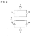
- the electrode tabs 14A to 14D and 15A to 15D of the flat batteries 10A to 10D are connected respectively to the external output positive electrode terminal 31, the external output negative electrode terminal 32, and the voltage detection terminal 37 via the bus bars 60, 70, 80, whereby the flat batteries 10A to 10D form a double-parallel, double-series connection configuration as shown in FIG. 5 .
- the voltage detection terminal 37 is a terminal used in order to detect the voltages of the flat batteries 10A to 10D constituting the battery module 1. Specifically, the voltages of the first flat battery 10A and the second flat battery 10B can be detecting by using the external output positive electrode terminal 31 and the voltage detection terminal 37 and measuring the voltage between these terminals. The voltages of the third flat battery 10D and the fourth flat battery 10D can be detecting by using the external output negative electrode terminal 32 and the voltage detection terminal 37 and measuring the voltage between these terminals.
- bus bars 60, 80 are secured to the spacer 40 attached to the first flat battery 10A, and the bus bar 70 is secured to the spacer 40 attached to the third flat battery 10C, as shown in FIG. 4 .
- the bus bar 70 comprises an installation part 71 in contact with the spacer 40, and a terminal part 72 that functions as the external output negative electrode terminal 32.
- a first pin hole 74 through which a first pin member 114 (see FIGS. 8A , 8B, and 9 ) formed in a pallet 110 (described hereinafter) is passed.
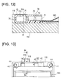
- a second pin hole 73 through which a second pin member 42 (see FIGS. 12 and 14 ) formed in the spacer 40 is passed.
- bus bar attachment device 100 Next, a bus bar attachment device 100 according to the present embodiment will be described.
- the bus bar attachment device 100 is a device for attaching the bus bar 70 to the flat battery 10 (referred to below simply as the "battery 10") to which the spacer 40 is attached.
- the bus bar 70 is electrically connected to the negative electrode tabs 15C, 15D of the electrode tabs 14A to 14D and 15A to 15D.
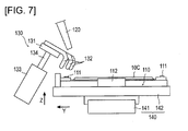
- the bus bar attachment device 100 has: a pallet 110 for placing the battery 10C in which the negative electrode tab 15C is led out; a spacer securing pin 111 (equivalent to the battery positioning part) which is provided to the pallet 110 and which settles the position of the battery 10C relative to the pallet 110; a bus bar positioning part 113 which is provided to the pallet 110 and which settles the position of the bus bar 70 relative to the pallet 110, the bus bar being electrically connected to the negative electrode tab 15C; a bus bar supply part 120 for supplying the bus bar 70 onto the pallet 110; a pressing part 130 for causing the bus bar 70 supplied by the bus bar supply part 120 to hit against the bus bar positioning part 113; and a conveying part 140 for holding and conveying the pallet 110.
- a pallet 110 for placing the battery 10C in which the negative electrode tab 15C is led out
- a spacer securing pin 111 (equivalent to the battery positioning part) which is provided to the pallet 110 and which settles the position of the battery 10C relative to the pallet
- the bus bar positioning part 113 comprises two adjacent wall surfaces (a first side surface 116A and a third side surface 116C, a second side surface 116B and the third side surface 116C, or the third side surface 116C and a bottom surface 117) that two adjacent surfaces of the bus bar 70 hit against.
- the pressing part 130 causes two adjacent surfaces in the bus bar 70 to hit against two adjacent wall surfaces in the bus bar positioning part 113.
- the bus bar 70 is supplied by the bus bar supply part 120 to a position where the two surfaces face the two wall surfaces in the bus bar positioning part 113, and the pressing part 130 causes the two surfaces to hit against the two wall surfaces in the bus bar positioning part 113 and settles the positions of the two surfaces relative to the battery 10C.
- the battery 10C comprises a spacer 40 laid over and attached to an electrode tab.
- the spacer securing pin 111 settles the position of the spacer 40 relative to the pallet 110 and thereby settles the position of the battery 10C relative to the pallet 110.
- the bus bar supply part 120 supplies the bus bar 70 onto the spacer 40 of the battery 10C placed on the pallet 110. The details are described below.
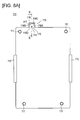
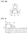
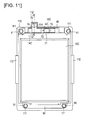
- the pallet 110 comprises the spacer securing pin 111 for inserting into the through-holes 41, 91 of the spacers 40, 90 and securing the spacers 40, 90, battery holding parts 112 for holding the pallet in contact with the side ends of the battery 10C, and the bus bar positioning part 113 for positioning the bus bar 70, as shown in FIGS. 8A , 9 , and 11 .
- the pallet 110 has the first pin member 114 inserted into the first pin hole 74 formed in the bus bar 70.
- the spacer 40 has the second pin member 42 inserted into the second pin hole 73 formed in the bus bar 70.
- the bus bar positioning part 113 has a fitting part 115 in which the terminal part 72 of the bus bar 70 is fitted.
- the first pin member 114 is disposed in proximity to the fitting part 115.
- the fitting part 115 has a substantially U-shaped side wall 116 rising up from the surface of the pallet 110 that carries the battery 10C, and a bottom surface 117 enclosed by the side wall 116.
- the side wall 116 In the inner sides of the side wall 116 are formed the opposing first side surface 116A and second side surface 116B, and the third side surface 116C positioned between the first side surface 116A and the second side surface 116B.
- the first to third side surfaces 116A to 116C and the bottom surface 117 constitute wall surfaces that are in contact with the terminal part 72 of the bus bar 70.
- An angle part 118 rising up at approximately 90 degrees is formed between the bottom surface 117 and the third side surface 116C.
- the first side surface 116A and the second side surface 116B as seen in the plan view shown in FIG. 8A , have a tapered shape in which there is a slight taper from an inlet port 116D of the fitting part 115 to the third side surface 116C.
- FIG. 8B is an exaggerated depiction of the tapered shape of the bus bar positioning part 113.
- the width dimension in the inlet port 116D of the fitting part 115 is w1
- the width dimension in the third side surface 116C is w2 (w1 > w2).
- the bus bar positioning part 113 has a substantially U-shaped side wall 116 rising up from the surface of the pallet 110 that carries the battery 10C, and has a tapered shape in which a taper is formed from the inlet port 116D opened in the side wall 116 to the side surface (the third side surface 116C) that faces the inlet port 116D.
- This tapered shape makes it easy for the terminal part 72 of the bus bar 70 to be led into the fitting part 115 through the inlet port 116D.
- the bus bar positioning part 113 comprises two adjacent wall surfaces which two adjacent surfaces in the bus bar 70 hit against. Two adjacent surfaces in the terminal part 72 of the bus bar 70 hit against two adjacent wall surfaces in the fitting part 115: the first side surface 116A and the third side surface 116C, and another two adjacent surfaces in the terminal part 72 of the bus bar 70 hit against two adjacent wall surfaces in the fitting part 115: the second side surface 116B and the third side surface 116C, whereby the position of the bus bar 70 in the width direction (the position in the left-to-right direction in FIGS. 8A and 8B ) relative to the pallet is set, and the lateral position (the position in the upward direction in FIGS. 8A and 8B ) of the bus bar 70 relative to the pallet 110 is set.
- the other two adjacent surfaces in the terminal part 72 of the bus bar 70 hit against two adjacent wall surfaces in the fitting part 115: the third side surface 116C and the bottom surface 117, whereby the height position (the position in the upward direction in FIG. 9 ) of the bus bar 70 relative to the pallet is set, and the lateral position (the position in the leftward direction in FIG. 9 ) of the bus bar 70 relative to the pallet 110 is set.
- the bus bar supply part 120 is configured from equipment such as a robot, for example.
- a robot hand 121 takes one bus bar 70 at a time from a plurality stored in and supplied from a tray or the like, and supplies the bus bar onto the pallet 110.
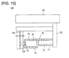
- the robot hand 121 has a stationary hand part 122 and a movable hand part 123 capable of moving toward and away from the stationary hand part 122, the terminal part 72 is gripped between the stationary hand part 122 and the movable hand part 123, and the bus bar 70 is supplied onto the spacer 40.
- the movable hand part 123 is provided with a clamp 124 for holding a portion of a nut hole 75 in the terminal part 72 of the bus bar 70.
- the clamp 124 has a semispherical shape, part of which fits into the nut hole 75. Due to the clamp 124 fitting into the nut hole 75, the robot hand 121 can reliably grip the terminal part 72 of the bus bar 70 and can supply the bus bar 70 with a stabilized orientation.
- the bus bar 70 is supplied by the bus bar supply part 120 to a position where two adjacent surfaces face two wall surfaces (the first side surface 116A and the third side surface 116C, the second side surface 116B and the third side surface 116C, or the third side surface 116C and the bottom surface 117) in the bus bar positioning part 113, and two adjacent surfaces are caused by the pressing part 130 to hit against two wall surfaces in the bus bar positioning part 113 to set the position relative to the battery 10C.
- the function of supplying the bus bar 70 and the function of positioning the bus bar 70 relative to the battery 10C are carried out by separate means, when the bus bar 70 is supplied to a position where two adjacent surfaces come to face two wall surfaces in the bus bar positioning part 113, the precision whereby the bus bar 70 is positioned relative to the pallet 110 may be comparatively low. Therefore, the bus bar 70 can be supplied at a high speed, and the cost of equipment such as the robot supplying the bus bar 70 can be reduced.
- the bus bar 70 is supplied by the bus bar supply part 120 to a position where the first pin member 114 is inserted into the first pin hole 74, whereby two surfaces in the terminal part 72 come to face two wall surfaces (the first side surface 116A and the third side surface 116C, the second side surface 116B and the third side surface 116C, or the third side surface 116C and the bottom surface 117) in the bus bar positioning part 113.
- the bus bar 70 is also supplied by the bus bar supply part 120 to a position where the second pin member 42 is inserted into the second pin hole 73, whereby two surfaces in the terminal part 72 come to face two wall surfaces (the first side surface 116A and the third side surface 116C, the second side surface 116B and the third side surface 116C, or the third side surface 116C and the bottom surface 117) in the bus bar positioning part 113.
- a gap of a certain size is provided between the external peripheral surface of the first pin member 114 and the inner peripheral surface of the first pin hole 74, and a gap of a certain size is provided between the external peripheral surface of the second pin member 42 and the inner peripheral surface of the second pin hole 73.
- the purpose of fitting together the first pin member 114 and the first pin hole 74 and fitting together the second pin member 42 and the second pin hole 73 is not to set the position of the bus bar 70 relative to the pallet 110.
- the purpose of these fittings is to place the bus bar 70 on the pallet 110 to an extent that the bus bar 70 can be made by the pressing part 130 to hit against the bus bar positioning part 113, or in other words, in a comparatively rough state.
- the pressing part 130 has a contact part 131 extending above the pallet 110 from a position in a lateral direction Y relative to the conveying direction X of the pallet 110, and the contact part 131 is brought in contact with the bus bar 70 and pulled laterally and downward, whereby two surfaces in the bus bar 70 hit against two wall surfaces in the bus bar positioning part 113. More specifically, the pressing part 130 comprises a contact part 131 in contact with the bus bar 70 and used for pressing the bus bar 70, and a drive part 133 having a drive source for moving the contact part 131 linearly.
- the contact part 131 has a plurality of pawls 132 extending downward, and the bottom ends of the pawls 132 come in contact with the bus bar 70.
- the drive source of the drive part 133 is a cylinder, a motor, or the like, for example, and is positioned in the lateral direction Y relative to the conveying direction X of the pallet 110.
- the drive part 133 comprises a drive shaft 134 inclined from a vertical direction Z, and the contact part 131 is moved in the lateral direction Y by moving the contact part 131 downward from above the pallet 110.
- the conveying part 140 has a pallet holding section 142 which is capable of moving along a guide rail 141 extending substantially horizontally, and which is capable of carrying the pallet 110, as shown in FIGS. 6 and 7 .
- the conveying part 140 is able to convey the pallet 110, the configuration is not limited, and the conveying part may be a conveyor or the like, for example.
- attaching the bus bar 70 is performed via a placement step, a supplying step, and a positioning step, and in the placement step, the battery 10C in which the negative electrode tab 15C is led out is placed on the pallet 110 in a state such that the position relative to the pallet 110 has been set.
- the bus bar 70 is supplied to a position where two adjacent surfaces in the bus bar 70 face two adjacent wall surfaces in the bus bar positioning part 113.
- the positioning step two adjacent surfaces in the supplied bus bar 70 are made to hit against two adjacent wall surfaces in the bus bar positioning part 113, and the position of the bus bar 70 relative to the battery 10C is set. The details are described below.
- the position of the spacer 40 relative to the pallet 110 is set, the spacer being laid on and attached to the negative electrode tab 15C of the battery 10C, whereby the position of the battery 10C relative to the pallet 110 is set.
- the spacer securing pins 111 of the pallet 110 are passed through the through-holes 41 of the spacer 40, and the battery holding parts 112 of the pallet 110 are brought in contact with the battery 10C, securing the battery 10C with the attached spacer 40 on the pallet 110 as shown in FIGS. 13 and 14 .
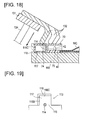
- the bus bar 70 is supplied onto the spacer 40 by the bus bar supply part 120 as shown in FIGS. 15 and 16 .
- the bus bar 70 is supplied to a position where the first pin member 114 provided to the pallet 110 is inserted into the first pin hole 74 provided to the bus bar 70, whereby two surfaces come to face two wall surfaces in the bus bar positioning part 113.
- the bus bar 7 is supplied to a position where the second pin member 42 provided to the spacer 40 is inserted into the second pin hole 73 provided to the bus bar 70, whereby two surfaces come to face two wall surfaces in the bus bar positioning part 113
- the bus bar 70 is placed on the pallet 110 to an extent that the bus bar 70 can be made by the pressing part 130 to hit against the bus bar positioning part 113.
- the contact part 131 of the pressing part 130 is positioned higher than the spacer 40 and the battery 10C on the pallet 110.
- the drive part 133 (see FIG. 7 ) is operated, causing the contact part 131, which extends above the pallet 110 from a position to the lateral direction Y relative to the conveying direction X of the pallet 110, to come in contact with the bus bar 70 and to be pulled in laterally and downward as shown in FIGS. 17 and 18 , whereby two surfaces in the bus bar 70 are made to hit against two wall surfaces in the bus bar positioning part 113 (refer to the arrow in FIG. 18 ).
- the bus bar 70 being pushed by the pawls 132 of the contact part 131, is thereby pressed toward the angle part 118 so as to come in contact with both the bottom surface 117 and the third side surface 116C which are adjacent, and the bus bar is positioned with high precision relative to the pallet 110. Because the spacer 40 has already been positioned with high precision relative to the pallet 110, the bus bar 70 is positioned with high precision relative to the pallet 110, and the bus bar 70 is positioned with high precision relative to the spacer 40 as well. At this time, the bus bar 70 is in contact with the negative electrode tab 15C of the battery 10C.
- the bus bar 70 is then bonded by ultrasonic welding or the like to the negative electrode tab 15C of the battery 10C.
- the bus bar 70 is supplied by the bus bar supply part 120 to a position where two surfaces come to face two wall surfaces (the first side surface 116A and the third side surface 116C, the second side surface 116B and the third side surface 116C, or the third side surface 116C and the bottom surface 117) in the bus bar positioning part 113, and the two surfaces are made by the pressing part 130 to hit against the two wall surfaces in the bus bar positioning part 113 to set the position relative to the battery 10C.
- the function of supplying the bus bar 70 and the function of positioning the bus bar 70 relative to the battery 10C are carried out by separate means, when the bus bar 70 is supplied to a position where two adjacent surfaces come to face two wall surfaces in the bus bar positioning part 113, the precision whereby the bus bar 70 is positioned relative to the pallet 110 may be comparatively low. Therefore, the bus bar 70 can be supplied at a high speed, and the cost of equipment such as the robot supplying the bus bar 70 can be reduced. Furthermore, because the two adjacent surfaces of the bus bar 70 are made to hit against the two wall surfaces in the bus bar positioning part 113, the position of the bus bar 70 relative to the battery can be set with high precision. Therefore, the work of attaching the bus bar 70 to the battery can be done faster and made less expensive, and the bus bar 70 can be positioned relative to the battery 10C with high precision.
- the pressing part 130 has a contact part 131 extending above the pallet 110 from a position in a lateral direction Y relative to the conveying direction X of the pallet 110, and the contact part 131 is brought in contact with the bus bar 70 and pulled laterally and downward, whereby two surfaces in the bus bar 70 hit against two wall surfaces in the bus bar positioning part 113. Due to the pressing part 130 being disposed in the lateral direction Y, clearance is formed above the pallet 110, and the next conveyed battery 10C and bus bar 70 can be supplied easily onto the pallet 110. In cases in which a pressing part is provided above the pallet 110, it has been necessary to increase the distance over which the pressing part retracts in order to guarantee a space for supplying the battery 10C and bus bar 70 onto the pallet 110. Due to the pressing part 130 being disposed in the lateral direction Y, however, the distance over which the pressing part 130 retracts can be reduced, and it is possible to speed up the manufacture of the battery 10C by speeding up the operation of the pressing part 130.
- the pallet 110 has the first pin member 114 inserted into the first pin hole 74 formed in the bus bar 70, and due to the bus bar 70 being supplied by the bus bar supply part 120 to a position where the first pin member 114 is inserted into the first pin hole 74, two surfaces come to face two wall surfaces in the bus bar positioning part 113. It is thereby possible to set the bus bar 70 on the battery 10C to an extent such that the bus bar 70 can be made to hit against the bus bar positioning part 113.
- the battery is 10 provided with a spacer 40 laid over and attached to the negative electrode tab 15C, the spacer securing pin 111 settles the position of the battery 10C relative to the pallet 110 by setting the position of the spacer 40 relative to the pallet 110, and the bus bar supply part 120 supplies the bus bar 70 onto the spacer 40 of the battery 10C placed on the pallet 110. Even with a battery 10C provided with a spacer 40, the bus bar 70 can be positioned with high precision relative to the battery 10C.
- the spacer 40 has a second pin member 42 inserted into the second pin hole 73 formed in the bus bar 70, and due to the bus bar 70 being supplied by the bus bar supply part 120 to a position where the second pin member 42 is inserted into the second pin hole 73, two surfaces come to face two wall surfaces in the bus bar positioning part 113. It is thereby possible to set the bus bar 70 on the spacer 40 of the battery 10C to an extent such that the bus bar 70 can be made to hit against the bus bar positioning part 113.
- the present invention is not limited to the embodiment described above, and can be modified as appropriate.
- the bus bar supply part 120 is not limited to equipment such as a robot, and the configuration is not limited as long as it is capable of supplying the bus bar 70.
- a battery 10C comprising a spacer 40 is depicted, but the present invention can also be applied to a battery 10C not comprising a spacer 40.
- the number of pawls 132 of the contact part 131 is not limited to three.
- a plurality of pressing parts 130 may also be provided.
- the bus bar 70 is positioned using two wall surfaces in the bus bar positioning part 113, but is not limited as such and can be positioned using any two or more wall surfaces from among the bottom surface 117, the first side surface 116A, the second side surface 116B, and the third side surface 116C. Therefore, the bus bar can be positioned using three wall surfaces, for example.
- the side wall 116 need not be formed into a substantial U shape.
- the fitting part 115 has a substantially L-shaped side wall 116 rising up from the surface of the pallet 110 that carries the battery 10C, and a bottom surface 117 adjacent to the side wall 116.
- this portion is opened up without forming the first side surface 116A, and the second side surface 116B and third side surface 116C are formed.
- the second and second side surfaces 116B, 116C and the bottom surface 117 constitute wall surfaces in contact with the terminal part 72 of the bus bar 70.
- An angle part (similar to the "angle part 118" in FIGS.
- the bus bar positioning part 113 comprises two adjacent wall surfaces (the second side surface 116B and the third side surface 116C, or the third side surface 116C and the bottom surface 117) which two adjacent surfaces in the bus bar 70 hit against.
- bus bar attachment device and method according to the present embodiment may be applied also to the bus bars 60, 80 other than the bus bar 70.
Landscapes
- Chemical & Material Sciences (AREA)
- Chemical Kinetics & Catalysis (AREA)
- Electrochemistry (AREA)
- General Chemical & Material Sciences (AREA)
- Engineering & Computer Science (AREA)
- Manufacturing & Machinery (AREA)
- Battery Mounting, Suspending (AREA)
- Connection Of Batteries Or Terminals (AREA)
Applications Claiming Priority (2)
| Application Number | Priority Date | Filing Date | Title |
|---|---|---|---|
| JP2012075688A JP6017812B2 (ja) | 2012-03-29 | 2012-03-29 | バスバー取り付け装置およびバスバー取り付け方法 |
| PCT/JP2013/055727 WO2013146097A1 (ja) | 2012-03-29 | 2013-03-01 | バスバー取り付け装置およびバスバー取り付け方法 |
Publications (3)
| Publication Number | Publication Date |
|---|---|
| EP2833433A1 true EP2833433A1 (de) | 2015-02-04 |
| EP2833433A4 EP2833433A4 (de) | 2015-12-30 |
| EP2833433B1 EP2833433B1 (de) | 2018-08-22 |
Family
ID=49259372
Family Applications (1)
| Application Number | Title | Priority Date | Filing Date |
|---|---|---|---|
| EP13768205.0A Not-in-force EP2833433B1 (de) | 2012-03-29 | 2013-03-01 | Sammelschienenbefestigungsvorrichtung und sammelschienenbefestigungsverfahren |
Country Status (5)
| Country | Link |
|---|---|
| US (1) | US9685648B2 (de) |
| EP (1) | EP2833433B1 (de) |
| JP (1) | JP6017812B2 (de) |
| CN (1) | CN104185911B (de) |
| WO (1) | WO2013146097A1 (de) |
Cited By (1)
| Publication number | Priority date | Publication date | Assignee | Title |
|---|---|---|---|---|
| EP3107135A4 (de) * | 2014-02-12 | 2017-03-01 | Nissan Motor Co., Ltd | Batteriemodul |
Families Citing this family (6)
| Publication number | Priority date | Publication date | Assignee | Title |
|---|---|---|---|---|
| WO2017068707A1 (ja) | 2015-10-22 | 2017-04-27 | 日産自動車株式会社 | 組電池の製造方法および製造装置 |
| US20190372079A1 (en) * | 2017-01-31 | 2019-12-05 | Envision Aesc Japan Ltd. | Battery pack production method and production device |
| USD855562S1 (en) | 2017-02-24 | 2019-08-06 | Ge Global Sourcing Llc | Battery module |
| WO2019186969A1 (ja) * | 2018-03-29 | 2019-10-03 | 株式会社 東芝 | 電池パック |
| USD1056851S1 (en) * | 2022-02-10 | 2025-01-07 | Redarc Technologies Pty Ltd. | Housing for a power distribution module |
| DE102022120606A1 (de) * | 2022-08-16 | 2024-02-22 | Bayerische Motoren Werke Aktiengesellschaft | Verbindungsvorrichtung für Batteriezellen einer Traktionsbatterie sowie Traktionsbatterie |
Family Cites Families (10)
| Publication number | Priority date | Publication date | Assignee | Title |
|---|---|---|---|---|
| JP2970331B2 (ja) | 1993-08-09 | 1999-11-02 | 住友電装株式会社 | バスバーの自動装着装置 |
| US7659029B2 (en) * | 2004-10-26 | 2010-02-09 | Nissan Motor Co., Ltd. | Battery module with insulating plates nipping electrode tabs |
| JP5010283B2 (ja) * | 2004-10-29 | 2012-08-29 | 日本電気株式会社 | 接合装置、収納ケースおよび電気デバイス集合体の製造方法 |
| JP2006302715A (ja) * | 2005-04-21 | 2006-11-02 | Nissan Motor Co Ltd | 電池モジュール集合体、電池モジュール集合体の製造方法、および電池モジュール集合体の製造装置 |
| JP4940718B2 (ja) * | 2005-07-04 | 2012-05-30 | 日産自動車株式会社 | 電池モジュールおよび電池モジュールの組み立て方法 |
| JP2008004366A (ja) | 2006-06-22 | 2008-01-10 | Sumitomo Wiring Syst Ltd | バスバー装着装置 |
| JP4775436B2 (ja) * | 2008-02-29 | 2011-09-21 | 日産自動車株式会社 | 電池モジュールおよび電池モジュールの製造方法 |
| KR101103755B1 (ko) * | 2008-09-03 | 2012-01-06 | 에스케이이노베이션 주식회사 | 버스 바 구비 리튬 2차 전지 단위 셋 및 버스 바 구비 리튬2차 전지 셋 |
| US8460817B2 (en) * | 2009-05-06 | 2013-06-11 | GM Global Technology Operations LLC | Method for manufacture of battery pouch terminals |
| JP2012221848A (ja) * | 2011-04-12 | 2012-11-12 | Toyota Motor Corp | 組電池の製造装置および組電池の製造方法 |
-
2012
- 2012-03-29 JP JP2012075688A patent/JP6017812B2/ja active Active
-
2013
- 2013-03-01 CN CN201380014976.8A patent/CN104185911B/zh not_active Expired - Fee Related
- 2013-03-01 WO PCT/JP2013/055727 patent/WO2013146097A1/ja not_active Ceased
- 2013-03-01 EP EP13768205.0A patent/EP2833433B1/de not_active Not-in-force
- 2013-03-01 US US14/380,094 patent/US9685648B2/en not_active Expired - Fee Related
Cited By (2)
| Publication number | Priority date | Publication date | Assignee | Title |
|---|---|---|---|---|
| EP3107135A4 (de) * | 2014-02-12 | 2017-03-01 | Nissan Motor Co., Ltd | Batteriemodul |
| US9812731B2 (en) | 2014-02-12 | 2017-11-07 | Nissan Motor Co., Ltd. | Battery module |
Also Published As
| Publication number | Publication date |
|---|---|
| WO2013146097A1 (ja) | 2013-10-03 |
| EP2833433B1 (de) | 2018-08-22 |
| JP2013206772A (ja) | 2013-10-07 |
| CN104185911A (zh) | 2014-12-03 |
| JP6017812B2 (ja) | 2016-11-02 |
| CN104185911B (zh) | 2016-06-15 |
| EP2833433A4 (de) | 2015-12-30 |
| US20150013150A1 (en) | 2015-01-15 |
| US9685648B2 (en) | 2017-06-20 |
Similar Documents
| Publication | Publication Date | Title |
|---|---|---|
| EP2833433B1 (de) | Sammelschienenbefestigungsvorrichtung und sammelschienenbefestigungsverfahren | |
| EP3637503B1 (de) | Batteriemodul mit busschienenanordnung | |
| CN111801810B (zh) | 包括内盖的电池模块 | |
| EP3671902B1 (de) | Batteriemodul mit busschienenanordnung | |
| US8771863B2 (en) | Battery module and manufacturing method of battery module | |
| EP2498318B1 (de) | Batteriepack | |
| US10468647B2 (en) | Battery pack | |
| EP2475023B1 (de) | Batterie und Batteriepack damit | |
| EP3076456A1 (de) | Batteriemodul und batteriepack damit | |
| EP2472635A1 (de) | Zusammengesetzte batterie und verfahren zur herstellung der zusammengesetzten batterie | |
| US9461280B2 (en) | Battery coupling method and battery coupling device | |
| US20120177978A1 (en) | Secondary battery, method of assembling the same, and battery pack including the secondary battery | |
| EP2899778A1 (de) | Batteriepack | |
| EP3664185B1 (de) | Elektroausrüstungsanordnung und batteriepack damit | |
| EP3664191A1 (de) | Elektrodenanordnung mit einem kunststoffelement, das auf ein verbindungsteil eines elektrodenlaschenträgers aufgebracht ist, und sekundärbatterie damit | |
| KR20160012021A (ko) | 단위전지모듈과 이를 포함하는 전지모듈 및 전지모듈의 제조방법과 이를 포함하는 전지팩 | |
| CN104919618A (zh) | 电池模块和电池组 | |
| US20240213625A1 (en) | Cell laminate | |
| KR102517098B1 (ko) | 배터리 모듈 | |
| US20170012258A1 (en) | Electricity storage module | |
| KR102915631B1 (ko) | 상하단 분리형 버스바프레임을 포함하는 배터리 모듈 및 이를 조립하는 방법 | |
| US9257722B2 (en) | Accumulator and method for the production of an accumulator | |
| KR20260026411A (ko) | 집전판, 이를 포함하는 이차 전지 및 그의 제조 방법 | |
| KR20260024349A (ko) | 이차 전지의 제조 방법, 이차 전지, 이를 포함하는 배터리 모듈, 배터리 팩 및 운송 수단 |
Legal Events
| Date | Code | Title | Description |
|---|---|---|---|
| PUAI | Public reference made under article 153(3) epc to a published international application that has entered the european phase |
Free format text: ORIGINAL CODE: 0009012 |
|
| 17P | Request for examination filed |
Effective date: 20140825 |
|
| AK | Designated contracting states |
Kind code of ref document: A1 Designated state(s): AL AT BE BG CH CY CZ DE DK EE ES FI FR GB GR HR HU IE IS IT LI LT LU LV MC MK MT NL NO PL PT RO RS SE SI SK SM TR |
|
| AX | Request for extension of the european patent |
Extension state: BA ME |
|
| DAX | Request for extension of the european patent (deleted) | ||
| RA4 | Supplementary search report drawn up and despatched (corrected) |
Effective date: 20151127 |
|
| RIC1 | Information provided on ipc code assigned before grant |
Ipc: H01R 11/28 20060101ALI20151123BHEP Ipc: H01M 2/20 20060101ALI20151123BHEP Ipc: H01M 2/10 20060101AFI20151123BHEP Ipc: H01M 10/04 20060101ALI20151123BHEP |
|
| GRAP | Despatch of communication of intention to grant a patent |
Free format text: ORIGINAL CODE: EPIDOSNIGR1 |
|
| STAA | Information on the status of an ep patent application or granted ep patent |
Free format text: STATUS: GRANT OF PATENT IS INTENDED |
|
| INTG | Intention to grant announced |
Effective date: 20180514 |
|
| GRAS | Grant fee paid |
Free format text: ORIGINAL CODE: EPIDOSNIGR3 |
|
| GRAA | (expected) grant |
Free format text: ORIGINAL CODE: 0009210 |
|
| STAA | Information on the status of an ep patent application or granted ep patent |
Free format text: STATUS: THE PATENT HAS BEEN GRANTED |
|
| AK | Designated contracting states |
Kind code of ref document: B1 Designated state(s): AL AT BE BG CH CY CZ DE DK EE ES FI FR GB GR HR HU IE IS IT LI LT LU LV MC MK MT NL NO PL PT RO RS SE SI SK SM TR |
|
| REG | Reference to a national code |
Ref country code: GB Ref legal event code: FG4D |
|
| REG | Reference to a national code |
Ref country code: CH Ref legal event code: EP |
|
| REG | Reference to a national code |
Ref country code: AT Ref legal event code: REF Ref document number: 1033489 Country of ref document: AT Kind code of ref document: T Effective date: 20180915 |
|
| REG | Reference to a national code |
Ref country code: IE Ref legal event code: FG4D |
|
| REG | Reference to a national code |
Ref country code: DE Ref legal event code: R096 Ref document number: 602013042426 Country of ref document: DE |
|
| REG | Reference to a national code |
Ref country code: NL Ref legal event code: MP Effective date: 20180822 |
|
| REG | Reference to a national code |
Ref country code: LT Ref legal event code: MG4D |
|
| PG25 | Lapsed in a contracting state [announced via postgrant information from national office to epo] |
Ref country code: GR Free format text: LAPSE BECAUSE OF FAILURE TO SUBMIT A TRANSLATION OF THE DESCRIPTION OR TO PAY THE FEE WITHIN THE PRESCRIBED TIME-LIMIT Effective date: 20181123 Ref country code: NO Free format text: LAPSE BECAUSE OF FAILURE TO SUBMIT A TRANSLATION OF THE DESCRIPTION OR TO PAY THE FEE WITHIN THE PRESCRIBED TIME-LIMIT Effective date: 20181122 Ref country code: BG Free format text: LAPSE BECAUSE OF FAILURE TO SUBMIT A TRANSLATION OF THE DESCRIPTION OR TO PAY THE FEE WITHIN THE PRESCRIBED TIME-LIMIT Effective date: 20181122 Ref country code: SE Free format text: LAPSE BECAUSE OF FAILURE TO SUBMIT A TRANSLATION OF THE DESCRIPTION OR TO PAY THE FEE WITHIN THE PRESCRIBED TIME-LIMIT Effective date: 20180822 Ref country code: NL Free format text: LAPSE BECAUSE OF FAILURE TO SUBMIT A TRANSLATION OF THE DESCRIPTION OR TO PAY THE FEE WITHIN THE PRESCRIBED TIME-LIMIT Effective date: 20180822 Ref country code: RS Free format text: LAPSE BECAUSE OF FAILURE TO SUBMIT A TRANSLATION OF THE DESCRIPTION OR TO PAY THE FEE WITHIN THE PRESCRIBED TIME-LIMIT Effective date: 20180822 Ref country code: IS Free format text: LAPSE BECAUSE OF FAILURE TO SUBMIT A TRANSLATION OF THE DESCRIPTION OR TO PAY THE FEE WITHIN THE PRESCRIBED TIME-LIMIT Effective date: 20181222 Ref country code: FI Free format text: LAPSE BECAUSE OF FAILURE TO SUBMIT A TRANSLATION OF THE DESCRIPTION OR TO PAY THE FEE WITHIN THE PRESCRIBED TIME-LIMIT Effective date: 20180822 Ref country code: LT Free format text: LAPSE BECAUSE OF FAILURE TO SUBMIT A TRANSLATION OF THE DESCRIPTION OR TO PAY THE FEE WITHIN THE PRESCRIBED TIME-LIMIT Effective date: 20180822 |
|
| REG | Reference to a national code |
Ref country code: AT Ref legal event code: MK05 Ref document number: 1033489 Country of ref document: AT Kind code of ref document: T Effective date: 20180822 |
|
| PG25 | Lapsed in a contracting state [announced via postgrant information from national office to epo] |
Ref country code: AL Free format text: LAPSE BECAUSE OF FAILURE TO SUBMIT A TRANSLATION OF THE DESCRIPTION OR TO PAY THE FEE WITHIN THE PRESCRIBED TIME-LIMIT Effective date: 20180822 Ref country code: LV Free format text: LAPSE BECAUSE OF FAILURE TO SUBMIT A TRANSLATION OF THE DESCRIPTION OR TO PAY THE FEE WITHIN THE PRESCRIBED TIME-LIMIT Effective date: 20180822 Ref country code: HR Free format text: LAPSE BECAUSE OF FAILURE TO SUBMIT A TRANSLATION OF THE DESCRIPTION OR TO PAY THE FEE WITHIN THE PRESCRIBED TIME-LIMIT Effective date: 20180822 |
|
| PG25 | Lapsed in a contracting state [announced via postgrant information from national office to epo] |
Ref country code: PL Free format text: LAPSE BECAUSE OF FAILURE TO SUBMIT A TRANSLATION OF THE DESCRIPTION OR TO PAY THE FEE WITHIN THE PRESCRIBED TIME-LIMIT Effective date: 20180822 Ref country code: ES Free format text: LAPSE BECAUSE OF FAILURE TO SUBMIT A TRANSLATION OF THE DESCRIPTION OR TO PAY THE FEE WITHIN THE PRESCRIBED TIME-LIMIT Effective date: 20180822 Ref country code: CZ Free format text: LAPSE BECAUSE OF FAILURE TO SUBMIT A TRANSLATION OF THE DESCRIPTION OR TO PAY THE FEE WITHIN THE PRESCRIBED TIME-LIMIT Effective date: 20180822 Ref country code: AT Free format text: LAPSE BECAUSE OF FAILURE TO SUBMIT A TRANSLATION OF THE DESCRIPTION OR TO PAY THE FEE WITHIN THE PRESCRIBED TIME-LIMIT Effective date: 20180822 Ref country code: IT Free format text: LAPSE BECAUSE OF FAILURE TO SUBMIT A TRANSLATION OF THE DESCRIPTION OR TO PAY THE FEE WITHIN THE PRESCRIBED TIME-LIMIT Effective date: 20180822 Ref country code: RO Free format text: LAPSE BECAUSE OF FAILURE TO SUBMIT A TRANSLATION OF THE DESCRIPTION OR TO PAY THE FEE WITHIN THE PRESCRIBED TIME-LIMIT Effective date: 20180822 Ref country code: EE Free format text: LAPSE BECAUSE OF FAILURE TO SUBMIT A TRANSLATION OF THE DESCRIPTION OR TO PAY THE FEE WITHIN THE PRESCRIBED TIME-LIMIT Effective date: 20180822 |
|
| REG | Reference to a national code |
Ref country code: DE Ref legal event code: R097 Ref document number: 602013042426 Country of ref document: DE |
|
| PG25 | Lapsed in a contracting state [announced via postgrant information from national office to epo] |
Ref country code: SM Free format text: LAPSE BECAUSE OF FAILURE TO SUBMIT A TRANSLATION OF THE DESCRIPTION OR TO PAY THE FEE WITHIN THE PRESCRIBED TIME-LIMIT Effective date: 20180822 Ref country code: DK Free format text: LAPSE BECAUSE OF FAILURE TO SUBMIT A TRANSLATION OF THE DESCRIPTION OR TO PAY THE FEE WITHIN THE PRESCRIBED TIME-LIMIT Effective date: 20180822 Ref country code: SK Free format text: LAPSE BECAUSE OF FAILURE TO SUBMIT A TRANSLATION OF THE DESCRIPTION OR TO PAY THE FEE WITHIN THE PRESCRIBED TIME-LIMIT Effective date: 20180822 |
|
| PLBE | No opposition filed within time limit |
Free format text: ORIGINAL CODE: 0009261 |
|
| STAA | Information on the status of an ep patent application or granted ep patent |
Free format text: STATUS: NO OPPOSITION FILED WITHIN TIME LIMIT |
|
| 26N | No opposition filed |
Effective date: 20190523 |
|
| PG25 | Lapsed in a contracting state [announced via postgrant information from national office to epo] |
Ref country code: SI Free format text: LAPSE BECAUSE OF FAILURE TO SUBMIT A TRANSLATION OF THE DESCRIPTION OR TO PAY THE FEE WITHIN THE PRESCRIBED TIME-LIMIT Effective date: 20180822 |
|
| REG | Reference to a national code |
Ref country code: DE Ref legal event code: R082 Ref document number: 602013042426 Country of ref document: DE Representative=s name: HOEFER & PARTNER PATENTANWAELTE MBB, DE Ref country code: DE Ref legal event code: R081 Ref document number: 602013042426 Country of ref document: DE Owner name: ENVISION AESC JAPAN LTD., ZAMA-SHI, JP Free format text: FORMER OWNERS: AUTOMOTIVE ENERGY SUPPLY CORPORATION, ZAMA-SHI, KANAGAWA, JP; NISSAN MOTOR CO., LTD., YOKOHAMA-SHI, JP |
|
| REG | Reference to a national code |
Ref country code: GB Ref legal event code: 732E Free format text: REGISTERED BETWEEN 20190926 AND 20191002 |
|
| PG25 | Lapsed in a contracting state [announced via postgrant information from national office to epo] |
Ref country code: MC Free format text: LAPSE BECAUSE OF FAILURE TO SUBMIT A TRANSLATION OF THE DESCRIPTION OR TO PAY THE FEE WITHIN THE PRESCRIBED TIME-LIMIT Effective date: 20180822 |
|
| REG | Reference to a national code |
Ref country code: CH Ref legal event code: PL |
|
| PG25 | Lapsed in a contracting state [announced via postgrant information from national office to epo] |
Ref country code: LU Free format text: LAPSE BECAUSE OF NON-PAYMENT OF DUE FEES Effective date: 20190301 |
|
| REG | Reference to a national code |
Ref country code: BE Ref legal event code: MM Effective date: 20190331 |
|
| PG25 | Lapsed in a contracting state [announced via postgrant information from national office to epo] |
Ref country code: LI Free format text: LAPSE BECAUSE OF NON-PAYMENT OF DUE FEES Effective date: 20190331 Ref country code: IE Free format text: LAPSE BECAUSE OF NON-PAYMENT OF DUE FEES Effective date: 20190301 Ref country code: CH Free format text: LAPSE BECAUSE OF NON-PAYMENT OF DUE FEES Effective date: 20190331 |
|
| PG25 | Lapsed in a contracting state [announced via postgrant information from national office to epo] |
Ref country code: BE Free format text: LAPSE BECAUSE OF NON-PAYMENT OF DUE FEES Effective date: 20190331 |
|
| PG25 | Lapsed in a contracting state [announced via postgrant information from national office to epo] |
Ref country code: TR Free format text: LAPSE BECAUSE OF FAILURE TO SUBMIT A TRANSLATION OF THE DESCRIPTION OR TO PAY THE FEE WITHIN THE PRESCRIBED TIME-LIMIT Effective date: 20180822 |
|
| PG25 | Lapsed in a contracting state [announced via postgrant information from national office to epo] |
Ref country code: PT Free format text: LAPSE BECAUSE OF FAILURE TO SUBMIT A TRANSLATION OF THE DESCRIPTION OR TO PAY THE FEE WITHIN THE PRESCRIBED TIME-LIMIT Effective date: 20181222 Ref country code: MT Free format text: LAPSE BECAUSE OF NON-PAYMENT OF DUE FEES Effective date: 20190301 |
|
| REG | Reference to a national code |
Ref country code: DE Ref legal event code: R079 Ref document number: 602013042426 Country of ref document: DE Free format text: PREVIOUS MAIN CLASS: H01M0002100000 Ipc: H01M0050200000 |
|
| PG25 | Lapsed in a contracting state [announced via postgrant information from national office to epo] |
Ref country code: CY Free format text: LAPSE BECAUSE OF FAILURE TO SUBMIT A TRANSLATION OF THE DESCRIPTION OR TO PAY THE FEE WITHIN THE PRESCRIBED TIME-LIMIT Effective date: 20180822 |
|
| PG25 | Lapsed in a contracting state [announced via postgrant information from national office to epo] |
Ref country code: HU Free format text: LAPSE BECAUSE OF FAILURE TO SUBMIT A TRANSLATION OF THE DESCRIPTION OR TO PAY THE FEE WITHIN THE PRESCRIBED TIME-LIMIT; INVALID AB INITIO Effective date: 20130301 |
|
| PG25 | Lapsed in a contracting state [announced via postgrant information from national office to epo] |
Ref country code: MK Free format text: LAPSE BECAUSE OF FAILURE TO SUBMIT A TRANSLATION OF THE DESCRIPTION OR TO PAY THE FEE WITHIN THE PRESCRIBED TIME-LIMIT Effective date: 20180822 |
|
| P01 | Opt-out of the competence of the unified patent court (upc) registered |
Effective date: 20230330 |
|
| PGFP | Annual fee paid to national office [announced via postgrant information from national office to epo] |
Ref country code: DE Payment date: 20240124 Year of fee payment: 12 Ref country code: GB Payment date: 20240125 Year of fee payment: 12 |
|
| PGFP | Annual fee paid to national office [announced via postgrant information from national office to epo] |
Ref country code: FR Payment date: 20240123 Year of fee payment: 12 |
|
| REG | Reference to a national code |
Ref country code: DE Ref legal event code: R119 Ref document number: 602013042426 Country of ref document: DE |
|
| GBPC | Gb: european patent ceased through non-payment of renewal fee |
Effective date: 20250301 |
|
| PG25 | Lapsed in a contracting state [announced via postgrant information from national office to epo] |
Ref country code: DE Free format text: LAPSE BECAUSE OF NON-PAYMENT OF DUE FEES Effective date: 20251001 |
|
| PG25 | Lapsed in a contracting state [announced via postgrant information from national office to epo] |
Ref country code: GB Free format text: LAPSE BECAUSE OF NON-PAYMENT OF DUE FEES Effective date: 20250301 |
|
| PG25 | Lapsed in a contracting state [announced via postgrant information from national office to epo] |
Ref country code: FR Free format text: LAPSE BECAUSE OF NON-PAYMENT OF DUE FEES Effective date: 20250331 |