EP2833512B1 - Procédé et dispositif de transmission d'électricité, ainsi que dispositif résonant utilisé dans ceux-ci - Google Patents
Procédé et dispositif de transmission d'électricité, ainsi que dispositif résonant utilisé dans ceux-ci Download PDFInfo
- Publication number
- EP2833512B1 EP2833512B1 EP13769519.3A EP13769519A EP2833512B1 EP 2833512 B1 EP2833512 B1 EP 2833512B1 EP 13769519 A EP13769519 A EP 13769519A EP 2833512 B1 EP2833512 B1 EP 2833512B1
- Authority
- EP
- European Patent Office
- Prior art keywords
- waveguide
- dielectric resonator
- transmission
- mode
- distance
- Prior art date
- Legal status (The legal status is an assumption and is not a legal conclusion. Google has not performed a legal analysis and makes no representation as to the accuracy of the status listed.)
- Active
Links
Images


Classifications
-
- H—ELECTRICITY
- H02—GENERATION; CONVERSION OR DISTRIBUTION OF ELECTRIC POWER
- H02J—ELECTRIC POWER NETWORKS; CIRCUIT ARRANGEMENTS OR SYSTEMS FOR SUPPLYING OR DISTRIBUTING ELECTRIC POWER; SYSTEMS FOR STORING ELECTRIC ENERGY
- H02J50/00—Circuit arrangements or systems for wireless supply or distribution of electric power
- H02J50/70—Circuit arrangements or systems for wireless supply or distribution of electric power involving the reduction of electric, magnetic or electromagnetic leakage fields
-
- H—ELECTRICITY
- H01—ELECTRIC ELEMENTS
- H01P—WAVEGUIDES; RESONATORS, LINES, OR OTHER DEVICES OF THE WAVEGUIDE TYPE
- H01P5/00—Coupling devices of the waveguide type
- H01P5/02—Coupling devices of the waveguide type with invariable factor of coupling
- H01P5/022—Transitions between lines of the same kind and shape, but with different dimensions
- H01P5/024—Transitions between lines of the same kind and shape, but with different dimensions between hollow waveguides
-
- H—ELECTRICITY
- H02—GENERATION; CONVERSION OR DISTRIBUTION OF ELECTRIC POWER
- H02J—ELECTRIC POWER NETWORKS; CIRCUIT ARRANGEMENTS OR SYSTEMS FOR SUPPLYING OR DISTRIBUTING ELECTRIC POWER; SYSTEMS FOR STORING ELECTRIC ENERGY
- H02J50/00—Circuit arrangements or systems for wireless supply or distribution of electric power
- H02J50/10—Circuit arrangements or systems for wireless supply or distribution of electric power using inductive coupling
- H02J50/12—Circuit arrangements or systems for wireless supply or distribution of electric power using inductive coupling of the resonant type
-
- H—ELECTRICITY
- H02—GENERATION; CONVERSION OR DISTRIBUTION OF ELECTRIC POWER
- H02J—ELECTRIC POWER NETWORKS; CIRCUIT ARRANGEMENTS OR SYSTEMS FOR SUPPLYING OR DISTRIBUTING ELECTRIC POWER; SYSTEMS FOR STORING ELECTRIC ENERGY
- H02J50/00—Circuit arrangements or systems for wireless supply or distribution of electric power
- H02J50/20—Circuit arrangements or systems for wireless supply or distribution of electric power using microwaves or radio frequency waves
Definitions
- the present invention relates to a power transmission apparatus and method for wirelessly transmitting power by a high-frequency electromagnetic wave such as a microwave, and a resonance device used therein.
- an electromagnetic induction type wireless power transmission is mainly used.
- a pair of coils is disposed adjacent to each other, and a magnetic field line generated at one coil passes through the other coil.
- This method has already been put to practical use because the transmission efficiency is high and the miniaturization of the apparatus can be achieved.
- an electromagnetic field resonance method is suitable.
- NPL 1 two spiral antenna resonators, of which both ends are opened, are disposed opposite to each other, and perform power transmission mostly by magnetic coupling.
- resonance frequencies are 122 KHz, 13.56 MHz, and 1.49 GHz
- relationships between a transmission distance and a transmission efficiency at each resonance frequency have been compared.
- the transmission efficiency is 90% or less even when the transmission distance is 100 mm.
- the transmission efficiency is reduced up to 50% when the transmission distance is 1,000 mm. Furthermore, when the transmission distance is increased, the transmission efficiency is rapidly reduced. In the experiment of 13.56-MHz resonance frequency, the transmission efficiency of 90% or more is maintained when the transmission distance is up to 220 mm. Furthermore, when the transmission distance is increased, the transmission efficiency is rapidly reduced. The transmission distance at which the transmission efficiency is 50% is about 300 mm. Also, in the experiment of 1.49-GHz resonance frequency, perhaps because a Q value of a resonator constituting a coil is low or a radiation occurs, the transmission efficiency is 90% or less. The transmission efficiency is rapidly reduced when the transmission distance is 3 mm or more. The transmission distance at which the transmission efficiency is 50% is about 4 mm.
- the two methods as described above transmit power to a region corresponding to a distance before a generated electromagnetic field, called a near field (short-distance field), is still formed as an electromagnetic wave that is a radio wave.
- a far field (long-distance field) corresponding to a region farther than the near field is a region in which an electromagnetic wave is radiated as a radio wave.
- the transmission distance at which the transmission efficiency is around 50% is ⁇ ⁇ 1/2460 when the resonance frequency is 122 KHz, ⁇ ⁇ 0.014 when the resonance frequency is 13.56 MHz, and ⁇ ⁇ 0.02 when the resonance frequency is 1.49 GHz, and power is all transmitted within the range of the near field.
- PTL 1 proposes a method that transmits energy by using a spherical dielectric resonator.
- energy transmission is performed by configuring and arranging two spherical dielectric resonators in the region of the near field such that one is coupled under a condition of a radiation caustic surface of the other.
- a method using a microwave of several hundreds of MHz or more and a rectenna antenna As represented by a space solar power satellite (SPS), a radio wave generated by converting high power obtained by solar power generation in space into a microwave is formed in a beam shape by using an antenna array, is transmitted to the earth from a position located 3,600 Km away, and is received by a rectenna antenna.
- SPS space solar power satellite
- a system for carrying out this method requires a plurality of antennas and needs to control a phase of power supplied to the respective antennas. This is large-scale and expensive. Research has been conducted to apply this technology to a system for charging a battery of a parked electric vehicle, but this is also expensive as in the SPS.
- PTL 2 discloses a resonator device in which a dielectric resonator is disposed within a cutoff waveguide such that an axis of the dielectric resonator is matched with a propagation direction of electromagnetic energy in the cutoff waveguide.
- a radio wave lens or a dielectric lens which is made of a dielectric material, is generally disposed so as to suppress the divergence of an electromagnetic wave.
- a filter built-in type electromagnetic horn antenna includes a waveguide, cylindrical dielectric members and a cylinder, and the cylindrical dielectric member and the waveguide at its outside form a dielectric resonator.
- a dielectric antenna has an at least partially dielectric body and an electrically conductive sheath, wherein the dielectric body can be struck on a supply section with electromagnetic radiation and the electromagnetic radiation can be at least partially emitted from the dielectric body via a lens-shaped radiation section.
- the conductive sheath essentially surrounds the dielectric body from the supply section to the radiation section and a supply opening is provided in the conductive sheath in the area of the supply section and a radiation opening is provided in the conductive sheath in the area of the radiation section.
- ⁇ NPL 1 ⁇ Proposal of antenna for wireless power transfer via magnetic resonant coupling in kHz-MHz-GHz
- ⁇ NPL 2 ⁇ Wireless power transfer via strongly coupled magnetic resonances
- the coupling coefficient K tends to be reduced when the distance between two resonators is increased. Therefore, in order to increase the transmission distance, it is suitable to use the resonator with a high Q value.
- the coupling coefficient K In the electromagnetic field resonance method, in a case where the Q value of the coil is about 10 to 100, the coupling coefficient K is required to be 0.9 to 0.1 so as to obtain the transmission efficiency of 80% or more. In a case where the Q value of the coil is about 1,000 to 2,000, the coupling coefficient K is required to be 0.08 to 0.04 so as to obtain the transmission efficiency of 80% or more.
- the coupling coefficient K is reduced when attempting to increase the transmission distance.
- the Q value can be increased by increasing the cross-sectional area of the coil.
- there is a limit such as an increase in a weight of the coil and a material cost, resulting in an increase in a price.
- paragraph [0041] of PTL 1 describes that "a method based on resonance with respect to wireless non-radiation type energy transmission is provided.”
- Paragraph [0023] describes that "in the case of the non-radiation type, the near field region has to be used, and the size of the region is roughly set by the wavelength ⁇ .”
- paragraph [0014] describes that "the attenuation occurs before the tail becomes oscillatory (radioactive) over a sufficiently long distance.
- a limiting surface (place where a change in the behavior of the electromagnetic wave occurs) is called a "radiation caustic surface”.
- the distance between the objects to be coupled must be set such that one is present within the other radiation caustic surface.”
- the distance of the "near field” and the “radiation caustic surface” is unclear, but it relates to the power transmission in a region before being “radioactive” according to "coupling mode principle” described in paragraph [0009].
- the present invention has been made in view of the above circumstances, and an object of the present invention is to provide a power transmission apparatus and method capable of transmitting power, with a high transmission efficiency, over a wide range from a near field to a far field through a simple configuration, and a resonance device used therein.
- a power transmission apparatus which wirelessly transmits power from a first resonance device to a second resonance device
- the first resonance device includes a first waveguide, a first dielectric resonator disposed coaxial with the first waveguide, and a first excitation structure for exciting the first dielectric resonator
- one end of the first waveguide is an open end and the other end of the first waveguide is a short-circuited end
- the first dielectric resonator has two first end surfaces disposed on opposite sides to each other, is insulated from the first waveguide in the vicinity of the open end of the first waveguide, and is disposed within the first waveguide, such that a thickness being a distance between the two first end surfaces is constant, regardless of a radial position of the first dielectric resonator
- the second resonance device includes a second waveguide, a second dielectric resonator disposed coaxial with the second waveguide, and a second excitation structure for exciting the second dielectric re
- the two first end surfaces or the two second end surfaces are made of planes parallel to each other and substantially perpendicular to a wave guiding direction of the first waveguide or a wave guiding direction of the second waveguide.
- the two first end surfaces or the two second end surfaces are located such that a central portion is farther from the second dielectric resonator or the first dielectric resonator than an outer peripheral portion.
- At least one of the two first end surfaces or at least one of the two second end surfaces is made of at least a part of a conical surface, a pyramid surface, a spherical surface, a parabolic surface, or an elliptical surface, which has a symmetrical axis coaxial with the first waveguide or the second waveguide in at least the outer peripheral portion.
- a shape of the first dielectric resonator or the second dielectric resonator is a polygonal prism, a polygonal cylinder, a cylindrical prism, or a circular cylinder, which has the first end surface or the second end surface as both end surfaces.
- a cross-sectional shape of the first waveguide or the second waveguide is a polygonal cylinder or a circular cylinder.
- the first waveguide or the second waveguide has a tapered shape such that a cross-sectional area is gradually reduced from the open end to the short-circuited end.
- the first excitation structure or the second excitation structure is disposed to be insulated from the first waveguide or the second waveguide in the short-circuited end of the first waveguide or the short-circuited end of the second waveguide, and includes a conductor extending in a wave guiding direction within the first waveguide or the second waveguide.
- a power transmission method which wirelessly transmits power from a first resonance device to a second resonance device by using the power transmission apparatus above, the power transmission method comprising:
- a power transmission apparatus capable of transmitting power, with a high transmission efficiency, over a wide range from a near field to a far field through a simple configuration.
- a power transmission apparatus which further increases a transmission distance, is provided by using a parallel-plate type dielectric resonator having the highest Q value or a dielectric resonator similar thereto.
- the dielectric resonator similar to the parallel-plate type dielectric resonator doesn't mean the parallel-plate type dielectric resonator but means a dielectric resonator shaped such that a thickness being a distance between two end surfaces is constant, regardless of a radial position of the dielectric resonator.
- the parallel-plate type dielectric resonator is mainly described, but the same is also true of the dielectric resonator similar to the parallel-plate type dielectric resonator.
- a resonator having a high Q value since a resonator having a high Q value is provided, it is possible to maintain K ⁇ Q (or KQ), which is an index of a transmission efficiency, to be large, and maintain a high transmission efficiency, even when a coupling coefficient K is small. Furthermore, according to the present invention, since various resonance modes exist in the parallel-plate type dielectric resonator, it is possible to further widen a facing area more than a coil or an antenna, increase a coupling coefficient K, and further increase KQ. Thus, according to the present invention, there is provided a power transmission apparatus in which a transmission efficiency is not reduced even when a transmission distance is further increased.
- a power transmission apparatus in which a Q value of a resonance system can be increased by a configuration that radiates an electromagnetic wave in one direction, and thus, even when a coupling coefficient K is extremely small, an electromagnetic wave radiated from one dielectric resonator can be efficiently received by the other dielectric resonator, thereby transmitting power to a far field at a high transmission efficiency.
- the present invention since there is no need to use a plurality of antennas requiring phase control as in a conventional power transmission apparatus of a far field by a microwave, it is possible to provide a practical power transmission apparatus capable of transmitting power to a far field with a small number of components and at a low cost.
- two first end surfaces or two end surfaces are located such that a central portion is farther from a second dielectric resonator or a first dielectric resonator than an outer peripheral portion.
- at least one of the two first end surfaces or at least one of the two second end surfaces is made of at least a part of a conical surface, a pyramid surface, a spherical surface, a parabolic surface, or an elliptical surface, which has a symmetrical axis coaxial with a first waveguide or a second waveguide in at least the outer peripheral portion. Since an electromagnetic field to be diverged from the outer peripheral portion of one dielectric resonator can be concentrated in a required direction and be directed toward the other dielectric resonator, a transmission distance can be extended without increasing transmission loss.
- Fig. 1 illustrates a schematic sectional view of embodiment 1.
- a power transmission apparatus of the present embodiment is a power transmission apparatus that transmits power wirelessly from a first resonance device (disposed on the left side of Fig. 1 ) to a second resonance device (disposed on the right side of Fig. 1 ).
- the first resonance device includes a first waveguide (cylindrical waveguide of a cylindrical cross-sectional shape located on the left side in Fig. 1 (also referred to as "circular waveguide”)), a first dielectric resonator (dielectric resonator of a cylindrical shape located on the left side in Fig. 1 ), and a first excitation structure for exciting the first dielectric resonator (excitation line made of a center conductor of a coaxial cable disposed on the left side in Fig. 1 ).
- the first waveguide, the first dielectric resonator, and the first excitation structure are coaxially disposed.
- coaxial means a state of being disposed to "share an axis".
- the first dielectric resonator includes two first parallel ends located in parallel to each other on sides opposite to each other (both end surfaces located on the left side and the right side in Fig. 1 ). Since the first parallel ends are substantially perpendicular to a wave guiding direction of the first waveguide (horizontal direction in Fig. 1 ), the first dielectric resonator is insulated from the first waveguide in the vicinity of the open end of the first waveguide (by interposing a cylindrical Styrofoam located on the left side in Fig. 1 ) and is disposed within the first waveguide.
- the second resonance device has the same configuration as the first resonance device but is disposed in a direction opposite to the first resonance device. That is, the second resonance device includes a second waveguide (cylindrical waveguide of a cylindrical cross-sectional shape located on the right side in Fig. 1 ), a second dielectric resonator (dielectric resonator of a cylindrical shape located on the right side in Fig. 1 ), and a second excitation structure for exciting the second dielectric resonator (excitation line made of a center conductor of a coaxial cable located on the right side in Fig. 1 ).
- the second waveguide, the second dielectric resonator, and the second excitation structure are coaxially disposed. In the second waveguide, one end (left end in Fig.
- the second dielectric resonator includes two second parallel ends located in parallel to each other on sides opposite to each other (both end surfaces located on the left side and the right side in Fig. 1 ). Since the first parallel ends are substantially perpendicular to a wave guiding direction of the second waveguide (horizontal direction in Fig. 1 ), the second dielectric resonator is insulated from the second waveguide in the vicinity of the open end of the second waveguide (by interposing a cylindrical Styrofoam located on the right side in Fig. 1 ) and is disposed within the second waveguide.
- the first resonance device and the second resonance device are coaxially disposed such that the open end of the first waveguide and the open end of the second waveguide are opposite to each other, and power input to the first excitation structure is output from the second excitation structure.
- a resonance frequency is set to around 2.45 GHz and a TM01 ⁇ mode is used.
- a thickness thereof is equal to an axial dimension, namely a length L of the resonator.
- the cylindrical dielectric resonator is fixed to be coaxial with each other with respect to the cylindrical waveguide through a low-dielectric-loss insulator having a low relative dielectric constant and a low dielectric loss tangent, such as Styrofoam or Teflon (registered trademark).
- a coaxial cable in which a center conductor having a length of about 1/4 wavelength (about 30.6 mm at 2.45 GHz) (that is, a center conductor in which a length of the excitation line is about 30.6 mm) is exposed, is inserted into the short-circuited end of the cylindrical waveguide so as to be coaxial with the cylindrical waveguide and the cylindrical dielectric resonator.
- An external conductor of the coaxial cable is connected to the short-circuited end of the waveguide.
- a distance (gap) AG between the front end of the center conductor of the coaxial cable and the dielectric resonator is maintained and fixed to 23.0 mm. This is set as a unit (resonance device). Two units are manufactured.
- the open ends of the cylindrical waveguides are opposite to each other to have a coaxial shape, and an arbitrary distance is maintained.
- Power of around 2.45 GHz is supplied to the coaxial cable of one unit (first resonance device), and power is taken out from the coaxial cable of the other unit (second resonance device).
- a transmission distance (M) is a distance between two resonance devices, and in particular, a minimum distance among distances between the first waveguide or the first dielectric resonator of the first resonance device and the second waveguide or the second dielectric resonator of the second resonance device.
- the transmission distance (M) is the smaller distance of the distance Cut between two waveguides opposite to each other and the distance between two dielectric resonators opposite to each other.
- the distance Cut between the two cylindrical waveguides opposite to each other is equal to the distance between the two dielectric resonators opposite to each other.
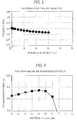
- Fig. 2 illustrates a transmission characteristic measured by setting a ratio of output power to input power as a transmission efficiency (relationship between a transmission distance and a transmission efficiency).
- the transmission efficiency becomes maximum, about 88%, at a transmission distance of around 7.5 mm, and the transmission efficiency is reduced even when closer or farther than that.
- a transmission distance at which the transmission efficiency is 50% is around about 25 mm. It can be seen that the transmission distance is 0.20 times as long as the wavelength ⁇ (in Table 1, how many times as long as the wavelength ⁇ is shown in a column of "wavelength ( ⁇ )"), is over 0.16 times as long as the wavelength ⁇ that is the limit of the near field, and reaches up to the far field.
- Fig. 3 illustrates a relationship between a transmission distance and a frequency at which a transmission efficiency is maximum. It can be seen that a resonance frequency change is smaller than 40 MHz.
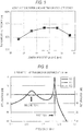
- Fig. 4 illustrates a transmission characteristic (relationship between the excitation line gap and the transmission efficiency) when a gap between the excitation line and the dielectric resonator (axial distance : excitation line gap) is changed.
- the transmission efficiency is almost maximized when the gap is around 23 mm.
- Fig. 5 illustrates a relationship between the length of the excitation line and the transmission efficiency when the transmission distance is 7.5 mm. Since an actual frequency is lower than 2.45 GHz, the transmission efficiency is almost maximized when the length of the excitation line is around 30.6 mm.
- Fig. 6 illustrates an S parameter when the transmission distance is 7.5 mm.
- a frequency is 2.437 GHz
- an attenuation of S21 is 0.56 dB
- a return loss of S11 is 24 dB.
- a frequency is 2.364 GHz
- S21 is 16 dB
- S11 is 1.5 dB.
- the two dielectric resonators opposite to each other are electric-field-coupled, and a coupling coefficient K is 0.030.
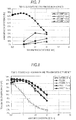
- Fig. 7 illustrates a relationship between a transmission distance and a transmission efficiency when two units are changed to the center distance of 5 mm, 10 mm, and 15 mm from the coaxial shape (that is, by shifting the axes).
- the transmission efficiency is rapidly lowered and becomes smaller than 50%.
- Fig. 8 illustrates a relationship between a transmission distance and a transmission efficiency when an axial position is set to the inside or the outside of the cylindrical waveguide from the flush.
- the dielectric resonator is drawn 5 mm on the outside of the cylindrical waveguide, the transmission efficiency is reduced and the transmission distance is also rapidly reduced.
- the dielectric resonator is put into about 5 to 10 mm inside of the cylindrical waveguide from the flush, the transmission efficiency is increased and the transmission distance is also increased.
- the dielectric resonator is put into 15 mm inside of the cylindrical resonator from the flush, the transmission efficiency is increased until the transmission distance becomes about 7.5 mm, but when beyond that, the transmission efficiency is almost the same as the case of the flush.
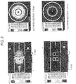
- Fig. 9 illustrates the result obtained when electromagnetic field analysis has been performed in electromagnetic field simulation.
- the mode of the dielectric resonator can be confirmed as being a TE01 ⁇ mode because there is no electromagnetic field change in a circumferential direction, there is one electromagnetic field change in a radial direction, and there is one electromagnetic field change in an axial direction. Also, since an electric field between the waveguides is strong, the dielectric resonators can be confirmed as being mostly coupled by the electric field.
- the dielectric resonator is inserted into the cutoff waveguide.
- a diameter of the cylindrical waveguide is 50.6 mm
- a cutoff frequency of a TM01 mode of the cylindrical waveguide is 4.54 GHz
- a cutoff frequency of a TM11 mode is 7.23 GHz
- a cutoff frequency of a TM02 mode is 10.40 GHz
- a cutoff frequency of a TE11 mode is 3.47 GHz
- a cutoff frequency of a TE21 mode is 5.77 GHz
- a cutoff frequency of a TE01 mode is 7.23 GHz. Therefore, it is a condition of a cutoff frequency or less.
- Fig. 10A illustrates an S parameter when two units in which the dielectric resonator is inserted 7.5 mm on the inside of the cylindrical waveguide are coaxially disposed and a gap (Cut) between the cylindrical waveguides is 0.5 mm.
- Fig. 10B illustrates an S parameter when a gap (AG) between the front end of the coaxial cable (that is, the front end of the excitation line) and the dielectric resonator is changed from 23 mm to 12 mm.
- AG gap
- This characteristic is a two-stage band pass filter in which a center frequency is 2.407 GHz, a bandwidth is about 6 MHz, and an insertion loss is about 0.2 dB (transmission efficiency is about 95%).
- Fig. 10C illustrates an S parameter when a gap between the cylindrical waveguides is 1.0 mm.
- This characteristic is a two-stage band pass filter in which a center frequency is 2.4075 GHz, a bandwidth is about 5 MHz, and an insertion loss is about 0.2 dB (transmission efficiency is about 95%).
- the power transmission apparatus in which the waveguide distance is 0.5 mm or 1.0 mm, can be applied for the purpose of reducing noise with low loss in a non-contact connector or a rotary joint of a waveguide.
- the configuration of the apparatus of embodiment 3 is substantially the same as that of embodiment 1 and corresponds to that illustrated in Fig. 1 .
- a diameter D is 55.6 mm
- a length L is 16.0 mm
- a diameter d of a cylindrical waveguide is 100.1 mm.
- a diameter D is 80.4 mm
- a length L is 16.3 mm
- a diameter d of a cylindrical waveguide is 144.8 mm.
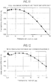
- Figs. 11 and 12 illustrate transmission characteristics (relationship between a transmission distance and a transmission efficiency) of a TM02 ⁇ mode and a TM03 ⁇ mode, respectively, which are measured by setting a distance between two cylindrical waveguides opposite to each other as a transmission distance and setting a ratio of output power to input power as a transmission efficiency.
- the transmission distance at which the transmission efficiency of the TM02 ⁇ mode is 50% is 48 mm, and the transmission distance is 0.40 times as long as the wavelength ⁇ . It can be seen that the transmission distance is over 0.16 times as long as the wavelength ⁇ that is the limit of the near field and reaches up to the far field.
- the transmission distance at which the transmission efficiency of the TM03 ⁇ mode is 50% is 66 mm, and the transmission distance is 0.54 times as long as the wavelength ⁇ . It can be seen that the transmission distance is over 0.16 times as long as the wavelength ⁇ that is the limit of the near field and reaches up to the far field.
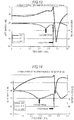
- Figs. 13 and 14 illustrate S parameters of the TM02 ⁇ mode and the TM03 ⁇ mode when the waveguide distance, namely the transmission distance, is 20 mm.
- a frequency is 2.450 GHz
- an attenuation of S21 is 0.53 dB
- a return loss of S11 is 50 dB.
- a frequency is 2.371 GHz
- S21 is 5 dB
- S11 is 6.5 dB.
- a frequency is 2.486 GHz
- an attenuation of S21 is 0.35 dB
- a return loss of S11 is 37 dB.
- a frequency is 2.441 GHz
- S21 is 9 dB
- S11 is 3 dB.
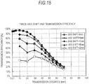
- Figs. 15 and 16 illustrate a relationship between a transmission distance and a transmission efficiency, respectively in the TM02 ⁇ mode and the TM03 ⁇ mode, when two units are changed to 5 mm, 10 mm, 15 mm, 20 mm, 25 mm, and 30 mm from the coaxial shape (that is, by shifting the axes).
- the transmission efficiency is reduced by several percent as compared with the case where the axis is not shifted 5 mm, and the transmission efficiency is maintained 50% or more even when the axis is shifted 15 mm.
- the transmission efficiency is reduced by several percent as compared with the case where the axis is not shifted 5 mm, and the transmission efficiency is maintained 50% or more even when the axis is shifted 20 mm.
- Figs. 17 and 18 illustrate a relationship between a transmission distance and a transmission efficiency, respectively in the TM02 ⁇ mode and the TM03 ⁇ mode, when the end surface of the dielectric resonator of the side opposite to the other unit is set to the inside or the outside of the cylindrical waveguide, instead of the position flush with the open end of the cylindrical waveguide.
- the transmission efficiency is reduced by ten to twenty of %. The transmission efficiency is further reduced with an increase in the transmission distance.
- the transmission efficiency is reduced by several %.
- the transmission efficiency is reduced by several % in a range from 5 mm on the outside of the cylindrical waveguide to 5 mm on the inside of the cylindrical waveguide.
- the transmission efficiency is further reduced by several 10%.
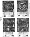
- Figs. 19 and 20 illustrate the result obtained when electromagnetic field analysis has been performed in electromagnetic field simulation, respectively in the TM02 ⁇ mode and the TM03 ⁇ mode.
- the mode of the dielectric resonator can be confirmed as being a TE02 ⁇ mode.
- the dielectric resonators can be confirmed as being mostly coupled by the electric field.
- the mode of the dielectric resonator can be confirmed as being a TE03 ⁇ mode. Also, since an electric field between the waveguides is strong, the dielectric resonators can be confirmed as being mostly coupled by the electric field.
- the cylindrical waveguide having a diameter of 100.1 mm is used as the TE02 ⁇ mode cylindrical waveguide, it is a condition of a frequency higher than a cutoff frequency in the TM01 and TE11 modes of the cylindrical waveguide mode being the same mode as the dielectric resonator. Since the cylindrical waveguide having a diameter of 144.8 mm is used as the TE03 ⁇ mode cylindrical waveguide, it is a condition of a frequency higher than a cutoff frequency in the TM01, TE11 mode and TE21 mode of the cylindrical waveguide mode being the same mode as the dielectric resonator.
- TM02 ⁇ mode electromagnetic field analysis has been performed when a diameter D of the dielectric resonator is 60.6 mm, a length thereof is 14.0 mm, and a diameter d of the cylindrical waveguide is 109.1 mm (see Table 1).
- the configuration of the apparatus of embodiment 4 is substantially the same as that of embodiment 1 and corresponds to that illustrated in Fig. 1 .
- a cylindrical dielectric resonator made of a dielectric ceramic material, of which a relative dielectric constant is 38, is used, and a TM012+ ⁇ mode designed around 2.45 GHz is used.
- a diameter D is 100.0 mm
- a length L is 26.51 mm
- a diameter d of a cylindrical waveguide is 180 mm.
- Fig. 21 illustrates a transmission characteristic (relationship between a transmission distance and a transmission efficiency), which is measured by setting a distance between two cylindrical waveguides opposite to each other as a transmission distance and setting a ratio of output power to input power as a transmission efficiency, and a relationship between a transmission distance and a transmission efficiency when two units are changed from a coaxial shape (that is, axes are shifted).
- the transmission distance at which the transmission efficiency is 50% is 72.5 mm.
- the transmission distance is 0.59 times as long as the wavelength ⁇ . It can be seen that the transmission distance is over 0.16 times as long as the wavelength ⁇ that is the limit of the near field and reaches up to the far field.
- the maximum transmission efficiency is shown at the transmission distance of around 50 mm.
- the transmission efficiency is reduced.
- the transmission efficiency of 50% can be maintained over the distance of around from 40 mm to 70 mm.
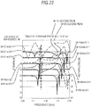
- Fig. 22 illustrates an S parameter when the waveguide distance is between 10 mm to 50 mm.
- a frequency is lowered as the waveguide distance is increased.
- a second peak is slightly increased as the waveguide distance is increased.
- the second peak does not appear over the waveguide distance of 20 mm to 30 mm and is not observed at the waveguide distance of 40 mm or 50 mm. That is, the coupling coefficient is not observed in the vicinity exceeding 19 mm, which is 0.16 times as long as the wavelength ⁇ that is the limit of the near field. Even when the coupling coefficient does not exist, power is transmitted.
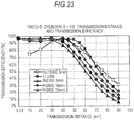
- Fig. 23 illustrates a relationship between a transmission distance and a transmission efficiency when the end surface of the dielectric resonator of the side opposite to the other unit is set to the inside or the outside of the cylindrical waveguide, instead of the position flush with the open end of the cylindrical waveguide.
- the transmission efficiency maintains 90% or more, except for the case where the dielectric resonator is set to 5 mm on the outside of the cylindrical waveguide.
- the transmission efficiency is rapidly reduced in sequence from the side where the resonator is disposed on the inside from the open end of the waveguide.
- the transmission distance distance between the waveguides
- the dielectric resonator when the dielectric resonator is put into 0 mm, 5 mm, 10 mm, and 15 mm inside (the distance between the dielectric resonators is set to 60 mm, 65 mm, 70 mm, and 75 mm), the coupling between the dielectric resonators becomes small and the transmission efficiency is rapidly reduced.
- the transmission efficiency is 50% or more up to the transmission distance of 60 mm.
- Fig. 24 illustrates the result obtained when electromagnetic field analysis has been performed in electromagnetic field simulation.
- the mode of the dielectric resonator can be confirmed as being a TE012+ ⁇ mode because there is no electromagnetic field change in a circumferential direction, there is one electromagnetic change in a radial direction, and there are two electromagnetic field changes in an axial direction. Also, since an electric field between the waveguides is strong, the dielectric resonators can be confirmed as being mostly coupled by the electric field.
- the waveguide having a diameter d of 180 mm is used as the cylindrical waveguide, it is a condition of a cutoff frequency or more in the TM01 mode, the TM11 mode, the TE11 mode, TE21 mode, and TE01 mode being the same cylindrical waveguide mode as the dielectric resonator, and in PTL 2, the cutoff waveguide (constituting a filter at a cutoff frequency or less) is used.
- the cutoff waveguide (constituting a filter at a cutoff frequency or less) is used.
- a power transmission apparatus is realized which maintains a high transmission efficiency at a cutoff frequency or more in any mode.
- the configuration of the apparatus of embodiment 5 is substantially the same as that of embodiment 1 and corresponds to that illustrated in Fig. 1 .
- Fig. 25 illustrates a schematic projection perspective view of a case where a dielectric resonator has a regular triangular prism shape.
- Fig. 26 illustrates a schematic projection perspective view of a case where a dielectric resonator has a square prism shape.
- Fig. 27 illustrates a schematic projection perspective view of a case where a dielectric resonator has a regular pentagonal prism shape.
- Fig. 28 illustrates a schematic projection perspective view of a case where a dielectric resonator has a regular hexagonal prism shape. Dimensions of the dielectric resonators of the respective shapes are shown in Table 1, which is to be described below.
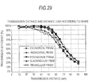
- Fig. 29 illustrates a relationship between a transmission distance and a transmission efficiency according to a shape of a dielectric resonator in the present embodiment.
- a cylindrical resonator shown for reference is shaped such that a diameter D of the resonator illustrated in embodiment 4 is 100 mm, a length L of the resonator is about 19 mm, and a diameter d of the cylindrical waveguide is 180 mm.
- the transmission distance at which the transmission efficiency is 50% is 68 mm, and the transmission distance is 0.56 times as long as the wavelength ⁇ . It can be seen that the transmission distance is over 0.16 times as long as the wavelength ⁇ that is the limit of the near field and reaches up to the far field.
- the transmission distance at which the transmission efficiency is 50% is 72 mm, and the transmission distance is 0.59 times as long as the wavelength ⁇ . It can be seen that the transmission distance is over 0.16 times as long as the wavelength ⁇ that is the limit of the near field and reaches up to the far field.
- a resonance mode can be set to a TM012+ ⁇ mode. Similar to the cylindrical dielectric resonator, a loss to a transmission distance of 50 mm can be maintained at 90% or more.
- a loss to a transmission distance of 50 mm can be maintained at 90% or more.
- the triangular prism or the rectangular prism many modes occur or there are many regions that do not directly contribute to resonance. Since this region is close to an inner cylinder of the cylindrical waveguide, transmission loss is gradually decreased by a factor that degrades a Q value or the like.
- FIG. 30 illustrates the result obtained when electromagnetic field analysis has been performed in electromagnetic field simulation so as to confirm whether the dielectric resonator of the hexagonal prism shape resonates in the TM012+ ⁇ in a similar manner to embodiment 4.
- the mode of the dielectric resonator can be confirmed as being a TE012+ ⁇ mode because there is no magnetic field change in a circumferential direction, there is one magnetic field change in a radial direction, and there are two electromagnetic field changes in an axial direction. Also, since an electric field between the waveguides is strong, the dielectric resonators can be confirmed as being mostly coupled by the electric field.
- a waveguide having a diameter of 187 to 216 mm is used as the waveguide, it is a condition of a cutoff frequency or more in the TM01 mode, the TM11 mode, the TE11 mode, TE21 mode, and TE01 mode being the same cylindrical waveguide mode as the dielectric resonator, and in PTL 2, the cutoff waveguide (constituting a filter at a cutoff frequency or less) is used.
- a power transmission apparatus is realized which maintains a high transmission efficiency at a cutoff frequency or more in any mode.
- the configuration of the apparatus of embodiment 6 is substantially the same as that of embodiment 1 and corresponds to that illustrated in Fig. 1 .
- a cylindrical dielectric resonator made of a dielectric ceramic material, of which a relative dielectric constant is 20, is used, and a TM012+ ⁇ mode designed around 2.45 GHz is used.
- the dielectric resonator configured such that a diameter D is 100 mm, a length L is 26.51 mm, and a diameter d of a cylindrical waveguide is 180 mm, and a dielectric resonator configured such that a diameter D is 140 mm, a length L is 29.5 mm, and a diameter d of a cylindrical waveguide is 216 mm are used.
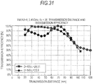
- Fig. 31 illustrates a relationship between a transmission distance and a transmission efficiency according to the present embodiment.
- the transmission efficiency is 50% when the transmission distance is 103 mm, and the transmission distance is 0.84 times as long as the wavelength ⁇ . It can be seen that the transmission distance is over 0.16 times as long as the wavelength ⁇ that is the limit of the near field and reaches up to the far field.
- the transmission efficiency is 50% when the transmission distance is 120 mm, and the transmission distance is 0.98 times as long as the wavelength ⁇ . It can be seen that the transmission distance is over 0.16 times as long as the wavelength ⁇ that is the limit of the near field and reaches up to the far field.
- a waveguide having a diameter of 216 mm is used as the waveguide, it is a condition of a cutoff frequency or more in the TM01 mode, the TM11 mode, the TE11 mode, TE21 mode, and TE01 mode being the same cylindrical waveguide mode as the dielectric resonator, and in PTL 2, the cutoff waveguide (constituting a filter at a cutoff frequency or less) is used.
- the cutoff waveguide (constituting a filter at a cutoff frequency or less) is used.
- a power transmission apparatus is realized which maintains a high transmission efficiency at a cutoff frequency or more in any mode.
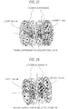
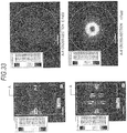
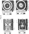
- Figs. 32 to 34 illustrate the results obtained when electromagnetic field analysis has been performed in electromagnetic field simulation.
- Fig. 32 illustrates a resonance mode when a transmission distance is 50 mm in a dielectric resonator having a diameter D of 100 mm
- Fig. 33 illustrates a resonance mode when a transmission distance is 20 mm in a dielectric resonator having a diameter D of 140 mm
- Fig. 34 illustrates a resonance mode when a transmission distance is 70 mm in a dielectric resonator having a diameter D of 140 mm.
- the mode of the dielectric resonator can be confirmed as being a TE012+ ⁇ mode because there is no magnetic field change in a circumferential direction, there is one magnetic field change in a radial direction, and there are two electromagnetic field changes in an axial direction.
- the transmission distance is 20 mm in the dielectric resonator having the diameter D of 140 mm
- the mode of the dielectric resonator can be confirmed as being a TE012+ ⁇ mode because there is no magnetic field change in a circumferential direction, there is one magnetic field change in a radial direction, and there are two electromagnetic field changes in an axial direction.
- the mode of the dielectric resonator can be confirmed as being a TE012+ ⁇ mode because, when a phase is 0 degrees, there is no magnetic field change in a circumferential direction, there is one magnetic field change in a radial direction, and there are two electromagnetic field changes in an axial direction. However, when the phase is around 90 degrees, there is no magnetic field change in a circumferential direction, there are four magnetic field changes in a radial direction, and there is one electromagnetic field change in an axial direction. Therefore, it can be seen that a resonance mode of a TE04 ⁇ mode also occurs and the mode of the dielectric resonator is a hybrid mode of the TE012+ ⁇ mode and the TE04 ⁇ mode.
- the configuration of the apparatus of embodiment 7 is substantially the same as that of embodiment 1 and corresponds to that illustrated in Fig. 1 .
- the cylindrical dielectric resonator used herein was configured to have a diameter D of 25 mm, an inner hole diameter of 15 mm, and a length L of 7.6 mm.
- the cylindrical waveguide used herein was configured to have a diameter d of 45 mm.
- the length of the excitation line was 6.25 mm (about 1/4 of the wavelength of 12 GHz), and the distance (gap) between the front end of the center conductor of the coaxial cable and the dielectric resonator was kept and fixed to 4.5 mm.
- Fig. 35 illustrates a schematic projection perspective view of the apparatus of the present embodiment.
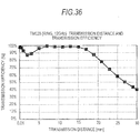
- Fig. 36 illustrates a relationship between a transmission distance and a transmission efficiency according to the present embodiment.
- the transmission efficiency is 50% when the transmission distance is 27 mm, and the transmission distance is 1.08 times as long as the wavelength ⁇ . It can be seen that the transmission distance is over 0.16 times as long as the wavelength ⁇ that is the limit of the near field and sufficiently reaches up to the far field.
- the transmission efficiency is 80% when the transmission distance is 21 mm, and the transmission distance is 0.84 times as long as the wavelength ⁇ . It can be seen that the transmission distance is over 0.16 times as long as the wavelength ⁇ that is the limit of the near field and reaches up to the far field
- Fig. 37 illustrates an S parameter when the transmission distance is 21 mm.
- a frequency is 11.256 GHz
- a value of S11 is 20 dB
- a value of S21 is 1.09 dB.
- 1.09 dB is 77.7% in the transmission efficiency.
- No second peak is observed. It is considered that this is because the transmission distance is far beyond 4 mm, which is 0.16 times as long as the wavelength ⁇ that is the limit of the near field.
- a waveguide having a diameter d of 45 mm is used as the cylindrical waveguide, it is a condition of a cutoff frequency or more in the TM01 mode, the TM11 mode, the TE11 mode, TE21 mode, and TE01 mode being the same cylindrical waveguide mode as the dielectric resonator, and in PTL 2, the cutoff waveguide (constituting a filter at a cutoff frequency or less) is used.
- a power transmission apparatus is realized which maintains a high transmission efficiency at a cutoff frequency or more in any mode.
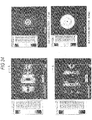
- Fig. 38 illustrates the result obtained when electromagnetic field analysis has been performed in electromagnetic field simulation.
- Fig. 38 illustrates an electromagnetic field distribution when the transmission distance is 21 mm.
- the mode of the dielectric resonator can be confirmed as being a TM02 ⁇ mode because there is no magnetic field change in a circumferential direction, there are two magnetic field changes in a radial direction, and there is one electromagnetic field change in an axial direction.
- a cylindrical dielectric resonator made of a dielectric ceramic material, of which a relative dielectric constant is 24, is used, and a TE012+ ⁇ mode designed around 12 GHz is used.
- the cylindrical dielectric resonator used herein is configured to have a diameter D of 14 mm and a length L of 3.75 mm.
- Fig. 39 illustrates a schematic projection perspective view of the apparatus of the present embodiment.
- Fig. 40 illustrates a schematic perspective view of the excitation structure in the present embodiment.
- the excitation structure is provided for exciting the cylindrical dielectric resonator in the TE mode and is called an Alford antenna.
- the excitation structure is described in Literature: "Ultrahigh-frequency loop antenna", Alford, A. and Kandoian, AIEE Trance.., 59, pp. 843-848 (1940 ). Currents in an axial direction are cancelled with each other, and the TE mode is efficiently excited within a cylindrical waveguide with a narrow space in order for excitation at a current in a circumferential direction.
- One end of the cylindrical waveguide is short-circuited.
- the cylindrical dielectric resonator In the vicinity of the open end of the waveguide, the cylindrical dielectric resonator is fixed to be coaxial with each other with respect to the cylindrical waveguide through a low-dielectric-loss insulator having a low relative dielectric constant and a low dielectric loss tangent, such as Styrofoam or Teflon (registered trademark).
- a coaxial cable is inserted into the short-circuited end of the cylindrical waveguide so as to be coaxial with the cylindrical waveguide and the cylindrical dielectric resonator.
- An external conductor of the coaxial cable is connected to the short-circuited end of the waveguide.
- An Alford antenna is attached to the front end of the coaxial cable, and a distance (gap) between the Alford antenna and the dielectric resonator is maintained and fixed to 3.0 mm. This is set as a unit (resonance device). Two units are manufactured. The open ends of the cylindrical waveguides are opposite to each other to have a coaxial shape, and an arbitrary distance is maintained. Power of about 12 GHz is supplied to the coaxial cable of one unit (first resonance device), and power is taken out from the coaxial cable of the other unit (second resonance device).
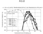
- Fig. 41 illustrates a relationship between a transmission distance and a transmission efficiency according to the present embodiment.
- the transmission efficiency becomes maximum, about 90%, in a transmission distance range of 3 mm to 9 mm, and the transmission efficiency is reduced even when the transmission distance is increased or decreased.
- a transmission distance at which the transmission efficiency is 50% is around about 15.5 mm.
- the transmission distance is 0.62 times as long as the wavelength ⁇ . It can be seen that the transmission distance is over 0.16 times as long as the wavelength ⁇ that is the limit of the near field and reaches up to the far field.
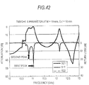
- Fig. 42 illustrates an S parameter when the transmission distance is 105 mm.
- a frequency is 11.045 GHz
- an attenuation of S21 is 0.86 dB
- a return loss of S11 is 29 dB.
- a frequency is 10.845 GHz
- S21 is 2 dB
- S11 is 13 dB.
- the dielectric resonators opposite to each other are magnetic-field-coupled, and when the first peak and the second peak show a coupling, a coupling coefficient K is 0.0183.
- Fig. 43 illustrates the result obtained when electromagnetic field analysis has been performed in electromagnetic field simulation.
- the mode of the dielectric resonator can be confirmed as being a TE012+ ⁇ mode because there is no electromagnetic field change in a circumferential direction, there is one electromagnetic change in a radial direction, and there is one electromagnetic field change in an axial direction. Also, since a magnetic field between the waveguides is strong, the dielectric resonators can be confirmed as being mostly coupled by the magnetic field.
- the dielectric resonator is inserted into the cutoff waveguide.
- the diameter of the cylindrical waveguide is 25.2 mm
- the cutoff frequency is 14.52 GHz when the diameter of the TE01 mode of the cylindrical waveguide being the same mode as the dielectric resonator is 25.2 mm.
- the cutoff frequency of the TE21 mode is 11.58 GHz
- the cutoff frequency of the TE11 mode is 6.98 GHz
- the cutoff frequency of the TM01 mode is 9.11 GHz
- the cutoff frequency of the TM11 mode is 14.52 GHz.
- the frequency is the cutoff frequency or more in the TE01 mode of the waveguide in which the dielectric resonator of at least the TE012+ ⁇ mode becomes a leaky mode.
- the cutoff waveguide (constituting a filter at a cutoff frequency or less) is used.
- a power transmission apparatus is realized which maintains a high transmission efficiency at a cutoff frequency or more.
- an excitation structure of the dielectric resonator including a coaxial cable and a dipole antenna of 1/2 wavelength connected thereto may be used.
- the excitation structure of the dielectric resonator as illustrated in Fig. 45 , an excitation structure that supplies power from a rectangular waveguide may be used. In this case, the resonator can be excited in the TM mode.
- the excitation structure of the dielectric resonator as illustrated in Fig. 46 , an excitation structure that supplies power from a rectangular waveguide may be used. In this case, the resonator can be excited in the TE mode.
- an excitation structure that supplies power from the an intermediate tap of an excitation line when the excitation line of about 1/4 wavelength extends from the internal surface of the waveguide in a direction perpendicular to a radial direction may be used.
- the resonator can be excited in the TE mode.
- the first or second waveguide may have a tapered shape such that a cross-sectional area is gradually reduced from an open end to a short-circuited end.
- the relative dielectric constant of the dielectric resonator used in the resonator is larger.
- the transmission distance at which the transmission efficiency is 50% is 72.5 mm in embodiment 4 when the relative dielectric constant is 38, but is 103 mm in embodiment 6 when the relative dielectric constant is 20.
- the transmission distance is larger when the relative dielectric constant is smaller.
- the larger diameter D of the dielectric resonator can further increase the transmission distance even when the dielectric resonators are in the same resonance mode and at the same relative dielectric constant.
- Fig. 49 illustrates a graph that can calculate the diameter D and the length L of the dielectric resonator when the frequency and the resonance mode of the cylindrical dielectric resonator are set.
- the value of the diameter D is calculated by selecting the resonance mode, determining one point on the graph (straight line) corresponding to the selected mode, reading the vertical-axis value of this point, and determining the wavelength ⁇ and the value of the relative dielectric constant Er.
- the value of the length L is calculated by reading the horizontal-axis value of the point and using the calculated D value.
- Fig. 49 illustrates a flowchart of examples shown in the embodiment.
- the resonators are electromagnetic-field-coupled before the electromagnetic field generated from the conductor, which is called a near field in the conventional art, becomes an electromagnetic wave state of a radio wave, and the transmission efficiency and the transmission distance are combined with each other by the coupling coefficient K and the Q value of the resonator.
- the apparatus that continuously transmit power even at the distance greater than the minimum distance where the coupling is formed, that is, from the near field to the far field by using the parallel-plate type dielectric resonator in the resonance system.
- the surfaces of the dielectric resonators larger than the wavelength or the 1/2 wavelength are easily arranged opposite to each other by using the dielectric resonators.
- the coil being three times longer (length of which is three times longer than the wavelength) is used, and the transmission distance of about half wavelength is not expected by the loss of the coil and the radiation of the radio wave.
- the transmission distance of the half wavelength or more is obtained by inserting the dielectric resonator having a diameter of about 122.5 mm into the cylindrical waveguide.
- the present invention is the apparatus that can transmit power continuously from the near field to the far field even when the waveguide as illustrated in PTL 2 is in the cutoff region or not.
- the present invention is the power transmission apparatus that can handle high power because the transmission efficiency is high.
- two first end surfaces or two second end surfaces was made of single planes parallel to each other and substantially perpendicular to the wave guiding direction of the first waveguide or the wave guiding direction of the second waveguide. That is, in the above embodiment, the first end surface is the first parallel end surface and the second end surface is the second parallel end surface.
- the two first end surfaces or the two second end surfaces located such that the central portion is farther from the second dielectric resonator or the first dielectric resonator than the outer peripheral portion are indicated by assigning separate embodiment numbers below.
- Figs. 50A and 50B illustrate configuration diagrams of embodiment A1.
- one of the two end surfaces is a concave conical surface, and the dimension of one end surface in the surface normal direction, namely the thickness L being the distance between the two end surfaces, is constant regardless of the radial position of the dielectric resonator.
- the dielectric resonator has a relative dielectric constant of 38, a diameter D of 105.3 mm, and a thickness L of 19.3 mm.
- the diameter of the short-circuited cylindrical waveguide is 1.8 times as long as the diameter D of the dielectric resonator which is 189.5 mm.
- the dielectric resonator is located at substantially the same axial position as the open side of the cylindrical waveguide.
- the conductor having a length of about 1/4 wavelength (30.6 mm) is located from the center of the open surface of the waveguide in the axial direction of the dielectric resonator, and the gap between the excitation line and the dielectric resonator is 23 mm.
- An arbitrary distance is maintained by matching the respective centers with the central axis of the dielectric resonator and arranging the open sides of the two cylindrical waveguides to be opposite to each other.
- the excitation line is attached to substantially the center of the short-circuited surface of the cylindrical waveguide, and the center conductor of the coaxial connector is connected to the excitation line.
- the microwave of about 2.45 GHz is supplied to the excitation line through one coaxial connector.
- the microwave power resonates one dielectric resonator from one excitation line and further resonates the other dielectric resonator maintained at an arbitrary distance, and the power transmitted to the other excitation line is taken out from the other coaxial connector. In this manner, the microwave power is transmitted from the connector of one cylindrical waveguide to the connector of the other cylindrical waveguide.
- Fig. 51 illustrates the transmission characteristic.
- the dielectric resonator operates as a two-stage filter that is resonated in the TM mode by the excitation line and the dielectric resonators are connected by the electric-field coupling.
- Figs. 52A to 52C illustrate a case where the distance between two dielectric resonators, namely the transmission distance M, is substantially the half of the diameter D of the dielectric resonator.
- the electromagnetic field generated from the outer peripheral portion, in particular the outer edge, of one dielectric resonator has a spreading portion D' spreading outward in radial direction. Therefore, the electromagnetic field portion that does not pass through the other dielectric resonator occurs.
- Fig. 52A to 52C illustrate a case where the distance between two dielectric resonators, namely the transmission distance M, is substantially the half of the diameter D of the dielectric resonator.
- the electromagnetic field generated from the outer peripheral portion, in particular the outer edge, of one dielectric resonator has a spreading portion D' spreading outward in radial direction. Therefore, the electromagnetic field portion that does not pass through the other dielectric resonator occurs.
- Figs. 52D to 52E illustrate a case where the distance between two dielectric resonators, namely the transmission distance M, is substantially the same as the diameter D of the dielectric resonator.
- the transmission distance of 50% transmission efficiency reaches 115 mm.
- the transmission distance of even 40 mm is expanded.
- both end surfaces of the dielectric resonators are made up of the conical surfaces all over the radial region from the outer peripheral portion to the central portion.
- the concave end surface can be configured as a truncated conical surface (conical dish surface) in which only the outer peripheral region is made up of a conical surface and the central region is made up of a plane perpendicular to the radial direction, and the end surface of the other side can be configured such that the thickness of the dielectric resonator becomes constant.
- the above operation and function can be appropriately set to be well exhibited.
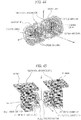
- Figs. 53 and 54 illustrate configuration diagrams of embodiment A2.
- the outer peripheral surface has a hexagonal pyramid shape, one of the two end surfaces is a concave hexagonal conical surface, and the dimension of one end surface in the surface normal direction, namely the thickness L being the distance between the two end surface, is constant regardless of the radial position of the dielectric resonator.
- a relative dielectric constant is 38
- a diameter of a circumscribed circle of a hexagon of an outer peripheral surface shape is 110 mm
- a diameter of an inscribed circle is 99.4 mm
- a thickness L is 19 mm
- an inclination angle of a hexagonal pyramid surface with respect to a plane perpendicular to an axial direction is 12°.
- a diameter of the cylindrical waveguide is 209 mm.
- the outer peripheral surface has a pentagonal prism shape, one of the two end surfaces is a concave pentagonal pyramid surface, and the dimension of one end surface in the surface normal direction, namely the thickness L being the distance between the two end surface, is constant regardless of the radial position of the dielectric resonator.
- a relative dielectric constant is 38
- a diameter of a circumscribed circle of a pentagon of an outer peripheral surface shape is 110 mm
- a diameter of an inscribed circle is 95.3 mm
- a thickness L is 19 mm
- an inclination angle of a pentagonal pyramid surface with respect to a plane perpendicular to an axial direction is 12°.
- a diameter of the cylindrical waveguide is 187 mm.
- Fig. 55 illustrates a relationship between a transmission efficiency and a transmission distance. The transmission distance of 50% transmission efficiency is expanded by 65 mm, that is, from 75 mm of the cylindrical dielectric resonator to 140 mm.
- the end surface of the dielectric resonator is made up of the pyramid surface (polygonal pyramid surface) all over the radial region from the outer peripheral portion to the central portion, but the pyramid is not limited to the pentagonal pyramid or the hexagonal pyramid.
- the outer peripheral region may be made up of the pyramid surface and the central region may be configured by a plane perpendicular to the axial direction. At a boundary position between the outer peripheral region and the central region, the operation and function described in embodiment A1 can be appropriately set to be well exhibited.
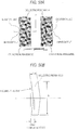
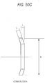
- Figs. 56A and 56B illustrate configuration diagrams of embodiment A3.
- both the two end surfaces are spherical surfaces, and the curvature radius of one end surface is greater than the curvature radius of the other end surface by the thickness L of the dielectric resonator. That is, the thickness L which is the distance between the two end surfaces is constant regardless of the radial position of the dielectric resonator.
- the dielectric resonator has a relative dielectric constant of 38, a diameter D of 105.3 mm, and a thickness L of 19 mm.
- a diameter of the cylindrical waveguide is 189.5 mm.
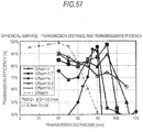
- 57 illustrates a relationship between a transmission efficiency and a transmission distance.
- the end surface of the dielectric resonator is made up of the spherical surface all over the radial region from the outer peripheral portion to the central portion, but, as one modification, only the outer peripheral region may be made up of the spherical surface and the central region may be configured by a plane perpendicular to the axial direction.
- the operation and function described in embodiment A1 can be appropriately set to be well exhibited.
- Figs. 58A and 58B illustrate configuration diagrams of embodiment A4.
- each dielectric resonator the first dielectric resonator or the second dielectric resonator
- one of the two end surfaces is a concave parabolic surface, and the dimension of one end surface in the surface normal direction, namely the thickness L being the distance between the two end surface, is constant regardless of the radial position of the dielectric resonator.
- the dielectric resonator has a relative dielectric constant of 38, a diameter D of 105.3 mm, and a thickness L of 19.3 mm.
- a diameter of the cylindrical waveguide is 189.5 mm.
- the end surface of the dielectric resonator is made up of the parabolic surface all over the radial region from the outer peripheral portion to the central portion, but, as one modification, only the outer peripheral region may be made up of the parabolic surface and the central region may be configured by a plane perpendicular to the axial direction.
- the operation and function described in embodiment A1 can be appropriately set to be well exhibited.
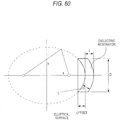
- Fig. 60 illustrates a configuration diagram of embodiment A5.
- each dielectric resonator (the first dielectric resonator or the second dielectric resonator)
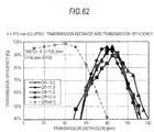
- one of the two end surfaces is a concave elliptical surface, and the dimension of one end surface in the surface normal direction, namely the thickness L being the distance between the two end surface, is constant regardless of the radial position of the dielectric resonator.
- the dielectric resonator has a relative dielectric constant of 38, a diameter D of 105.3 mm, and a thickness L of 19.3 mm.
- a diameter of the cylindrical waveguide is 189.5 mm. Relationships between a transmission efficiency and a transmission distance are illustrated in Fig.
- the end surface of the dielectric resonator is made up of the elliptical surface all over the radial region from the outer peripheral portion to the central portion, but, as one modification, only the outer peripheral region may be made up of the elliptical surface and the central region may be configured by a plane perpendicular to the axial direction.
- the operation and function described in embodiment A1 can be appropriately set to be well exhibited.
- one of the first dielectric resonator and the second dielectric resonator may have the end surface of one of embodiments A1 to A5, and the other may have the different end surface of one of embodiments A1 to A5.
- one of the first dielectric resonator and the second dielectric resonator may have the end surface of one of embodiments 1 to 8, and the other may have the end surface of one of embodiments A1 to A5.
Landscapes
- Engineering & Computer Science (AREA)
- Computer Networks & Wireless Communication (AREA)
- Power Engineering (AREA)
- Physics & Mathematics (AREA)
- Electromagnetism (AREA)
- Control Of Motors That Do Not Use Commutators (AREA)
- Waveguide Aerials (AREA)
Claims (8)
- Dispositif de transmission d'énergie pour une augmentation d'efficacité de transmission sur une large plage d'un champ proche à un champ lointain ; l'appareil de transmission d'énergie comprenant : un premier dispositif de résonance incluant un premier guide d'ondes, un premier résonateur diélectrique disposé coaxial au premier guide d'ondes, et une première structure d'excitation pour exciter le premier résonateur diélectrique ;
le premier guide d'ondes ayant une extrémité ouverte à une extrémité et une extrémité court-circuitée à l'autre extrémité,
le premier résonateur diélectrique ayant deux premières surfaces d'extrémité disposées sur des côtés opposés l'un à l'autre, étant isolé par rapport au premier guide d'ondes à proximité de l'extrémité ouverte du premier guide d'ondes, et étant disposé à l'intérieur du premier guide d'ondes, de manière qu'une épaisseur, qui est une distance entre les deux premières surfaces d'extrémité, soit constante, indépendamment d'une position radiale du premier résonateur diélectrique, caractérisé en ce que l'appareil de transmission d'énergie comprend un deuxième dispositif de résonance incluant un deuxième guide d'ondes, un deuxième résonateur diélectrique disposé coaxial au deuxième guide d'ondes, et une deuxième structure d'excitation pour exciter le deuxième résonateur diélectrique,
le deuxième guide d'ondes ayant une extrémité ouverte à une extrémité et une extrémité court-circuitée à l'autre extrémité,
le deuxième résonateur diélectrique ayant deux deuxièmes surfaces d'extrémité disposées sur des côtés opposés l'un à l'autre, étant isolé par rapport au deuxième guide d'ondes à proximité de l'extrémité ouverte du deuxième guide d'ondes, et étant disposé à l'intérieur du deuxième guide d'ondes, de manière qu'une épaisseur, qui est une distance entre les deux deuxièmes surfaces d'extrémité, soit constante, indépendamment d'une position radiale du deuxième résonateur diélectrique, et
le premier dispositif de résonance et le deuxième dispositif de résonance étant disposés de manière que l'extrémité ouverte du premier guide d'ondes et l'extrémité ouverte du deuxième guide d'ondes soient opposées l'une à l'autre, et une entrée d'énergie vers la première structure d'excitation étant délivrée en sortie à partir de la deuxième structure d'excitation ; dans lequel une des deux premières surfaces d'extrémité est disposée dans la position en affleurement avec l'extrémité ouverte du premier guide d'ondes ou à l'extérieur de l'extrémité ouverte du premier guide d'ondes dans la direction axiale du premier résonateur diélectrique, l'une de deux premières surfaces d'extrémité étant opposée au deuxième dispositif de résonance, et une de deux deuxièmes surfaces d'extrémité est disposée dans la position en affleurement avec l'extrémité ouverte du deuxième guide d'ondes ou à l'extérieur de l'extrémité ouverte du deuxième guide d'ondes dans la direction axiale du deuxième résonateur diélectrique, l'une de deux deuxièmes surfaces d'extrémité étant opposée au premier dispositif de résonance. - Dispositif de transmission d'énergie selon la revendication 1,
dans lequel les deux premières surfaces d'extrémité ou les deux deuxièmes surfaces d'extrémité sont constituées de plans parallèles entre eux et sensiblement perpendiculaires à une direction de guidage d'ondes du premier guide d'ondes ou une direction de guidage d'ondes du deuxième guide d'ondes. - Dispositif de transmission d'énergie selon la revendication 1,
dans lequel une première surface d'extrémité faisant face au deuxième résonateur diélectrique est une surface concave, la première surface d'extrémité étant une des deux premières surfaces d'extrémité, ou une deuxième surface d'extrémité faisant face au premier résonateur diélectrique est une surface concave, la deuxième surface d'extrémité étant une des deux deuxièmes surfaces d'extrémité. - Dispositif de transmission d'énergie selon la revendication 3,
dans lequel la première surface d'extrémité ou la deuxième surface d'extrémité est constituée d'au moins une partie d'une surface conique, d'une surface pyramidale, d'une surface sphérique, d'une surface parabolique ou d'une surface elliptique, qui a un axe de symétrie coaxial avec le premier guide d'ondes ou le deuxième guide d'ondes dans au moins une portion périphérique extérieure. - Dispositif de transmission d'énergie selon la revendication 2,
dans lequel une forme du premier résonateur diélectrique ou du deuxième résonateur diélectrique est un prisme polygonal, un cylindre polygonal, un prisme cylindrique ou un cylindre circulaire, qui a la première surface d'extrémité ou la deuxième surface d'extrémité pour les deux surfaces d'extrémité. - Dispositif de transmission d'énergie selon l'une quelconque des revendications 1 à 5,
dans lequel une forme en coupe transversale du premier guide d'ondes ou du deuxième guide d'ondes est un cylindre polygonal ou un cylindre circulaire. - Dispositif de transmission d'énergie selon l'une quelconque des revendications 1 à 5,
dans lequel le premier guide d'ondes ou le deuxième guide d'ondes a une forme effilée de manière qu'une section transversale soit progressivement réduite de l'extrémité ouverte à l'extrémité court-circuitée. - Dispositif de transmission d'énergie selon l'une quelconque des revendications 1 à 7,
dans lequel la première structure d'excitation ou la deuxième structure d'excitation est disposée pour être isolée par rapport au premier guide d'ondes ou au deuxième guide d'ondes dans l'extrémité court-circuitée du premier guide d'ondes ou l'extrémité court-circuitée du deuxième guide d'ondes, et inclut un conducteur s'étendant dans une direction de guidage d'ondes à l'intérieur du premier guide d'ondes ou du deuxième guide d'ondes.
Applications Claiming Priority (3)
| Application Number | Priority Date | Filing Date | Title |
|---|---|---|---|
| JP2012082365 | 2012-03-30 | ||
| JP2012199469 | 2012-09-11 | ||
| PCT/JP2013/057962 WO2013146494A1 (fr) | 2012-03-30 | 2013-03-21 | Procédé et dispositif de transmission d'électricité, ainsi que dispositif résonant utilisé dans ceux-ci |
Publications (3)
| Publication Number | Publication Date |
|---|---|
| EP2833512A1 EP2833512A1 (fr) | 2015-02-04 |
| EP2833512A4 EP2833512A4 (fr) | 2015-11-25 |
| EP2833512B1 true EP2833512B1 (fr) | 2019-06-05 |
Family
ID=49259751
Family Applications (1)
| Application Number | Title | Priority Date | Filing Date |
|---|---|---|---|
| EP13769519.3A Active EP2833512B1 (fr) | 2012-03-30 | 2013-03-21 | Procédé et dispositif de transmission d'électricité, ainsi que dispositif résonant utilisé dans ceux-ci |
Country Status (4)
| Country | Link |
|---|---|
| US (1) | US9577477B2 (fr) |
| EP (1) | EP2833512B1 (fr) |
| JP (1) | JP5850282B2 (fr) |
| WO (1) | WO2013146494A1 (fr) |
Families Citing this family (8)
| Publication number | Priority date | Publication date | Assignee | Title |
|---|---|---|---|---|
| JP5971703B2 (ja) * | 2012-06-15 | 2016-08-17 | 石崎 俊雄 | 無線電力伝送装置 |
| WO2015199077A1 (fr) * | 2014-06-25 | 2015-12-30 | 宇部興産株式会社 | Dispositif de transmission diélectrique sans contact et procédé de transmission sans contact |
| KR102522441B1 (ko) | 2015-11-09 | 2023-04-18 | 삼성전자주식회사 | 근거리 통신 안테나 장치 및 이를 구비한 전자 장치 |
| US10547350B2 (en) * | 2016-05-05 | 2020-01-28 | Texas Instruments Incorporated | Contactless interface for mm-wave near field communication |
| US10613254B2 (en) | 2017-05-24 | 2020-04-07 | Uchicago Argonne, Llc | Ultrathin, polarization-independent, achromatic metalens for focusing visible light |
| US10324314B2 (en) * | 2017-05-24 | 2019-06-18 | Uchicago Argonne, Llc | Ultra-flat optical device with high transmission efficiency |
| EP3675276B1 (fr) * | 2017-11-14 | 2023-07-26 | Huawei Technologies Co., Ltd. | Résonateur diélectrique et filtre |
| KR102858527B1 (ko) * | 2021-01-25 | 2025-09-12 | 삼성전자주식회사 | 링형 공진기 및 링형 공진기를 포함하는 무선 전력 송신 장치 |
Family Cites Families (12)
| Publication number | Priority date | Publication date | Assignee | Title |
|---|---|---|---|---|
| JPS58219802A (ja) | 1982-06-14 | 1983-12-21 | Komatsu Ltd | ホ−ンアンテナ |
| JPH0652841B2 (ja) | 1988-02-15 | 1994-07-06 | 株式会社村田製作所 | 共振器装置 |
| JPH02111107A (ja) * | 1988-10-19 | 1990-04-24 | Murata Mfg Co Ltd | フィルタ内蔵型電磁ラッパアンテナ |
| JP3160348B2 (ja) * | 1992-02-07 | 2001-04-25 | 日本原子力研究所 | 高周波加熱装置の障壁窓 |
| JPH10335096A (ja) * | 1997-06-03 | 1998-12-18 | Hitachi Ltd | プラズマ処理装置 |
| JP2000031727A (ja) | 1998-07-07 | 2000-01-28 | Ricoh Co Ltd | テーパードスロットアンテナ,1次元アンテナアレイおよび2次元アンテナアレイ |
| JP3692273B2 (ja) * | 2000-02-03 | 2005-09-07 | アルプス電気株式会社 | 一次放射器 |
| AU2006269374C1 (en) | 2005-07-12 | 2010-03-25 | Massachusetts Institute Of Technology | Wireless non-radiative energy transfer |
| US8264417B2 (en) * | 2007-06-19 | 2012-09-11 | The United States Of America As Represented By The Secretary Of The Navy | Aperture antenna with shaped dielectric loading |
| TWI361540B (en) | 2007-12-14 | 2012-04-01 | Darfon Electronics Corp | Energy transferring system and method thereof |
| DE102008020036B4 (de) * | 2008-04-21 | 2010-04-01 | Krohne Meßtechnik GmbH & Co KG | Dielektrische Antenne |
| JP5971703B2 (ja) * | 2012-06-15 | 2016-08-17 | 石崎 俊雄 | 無線電力伝送装置 |
-
2013
- 2013-03-21 JP JP2014507764A patent/JP5850282B2/ja not_active Expired - Fee Related
- 2013-03-21 US US14/389,748 patent/US9577477B2/en not_active Expired - Fee Related
- 2013-03-21 EP EP13769519.3A patent/EP2833512B1/fr active Active
- 2013-03-21 WO PCT/JP2013/057962 patent/WO2013146494A1/fr not_active Ceased
Non-Patent Citations (1)
| Title |
|---|
| None * |
Also Published As
| Publication number | Publication date |
|---|---|
| US9577477B2 (en) | 2017-02-21 |
| JPWO2013146494A1 (ja) | 2015-12-10 |
| EP2833512A1 (fr) | 2015-02-04 |
| US20150048692A1 (en) | 2015-02-19 |
| EP2833512A4 (fr) | 2015-11-25 |
| WO2013146494A1 (fr) | 2013-10-03 |
| JP5850282B2 (ja) | 2016-02-03 |
Similar Documents
| Publication | Publication Date | Title |
|---|---|---|
| EP2833512B1 (fr) | Procédé et dispositif de transmission d'électricité, ainsi que dispositif résonant utilisé dans ceux-ci | |
| Heebl et al. | Wireless links in the radiative near field via Bessel beams | |
| EP3347942B1 (fr) | Émission par réseau à déphasage hybride | |
| EP3790113B1 (fr) | Antenne double bande | |
| KR101345764B1 (ko) | 쿼시 야기 안테나 | |
| US20190132025A1 (en) | Excitation and use of guided surface waves | |
| Benassi et al. | Wireless power transfer in the radiative near-field through resonant Bessel-beam launchers at millimeter waves | |
| US9923385B2 (en) | Excitation and use of guided surface waves | |
| US9793612B1 (en) | Reduced profile leaky-wave antenna | |
| KR101755284B1 (ko) | 다면체 구조를 이용한 무선 전력 전송용 3차원 전 방향 공진기, 이를 포함하는 무선 전력 전송 장치 및 무선 전력 전송 시스템 | |
| EP3304639B1 (fr) | Excitation et utilisation d'ondes de surface guidées | |
| Leung et al. | Theory and experiment of the wideband two-layer hemispherical dielectric resonator antenna | |
| Zheng et al. | Broadband dual-polarized cup dielectric resonator antenna with stable omnidirectional radiation patterns | |
| Hamdalla et al. | Design of a 3d printed wide band metasurface antenna for high power applications | |
| CN109786970B (zh) | 一种X/Ka多频宽带多模馈源 | |
| Dong et al. | Generation of plane spiral orbital angular momentum microwave with ring dielectric resonator antenna | |
| CN107069190A (zh) | 高功率低轮廓螺旋天线及其构成的天线阵列 | |
| US20200373786A1 (en) | A system and apparatus for wireless power transfer | |
| Ray et al. | Multilayer multiresonator circular microstrip antennas for broadband and dual‐band operations | |
| EP4231457A1 (fr) | Source d'alimentation à double fréquence et antenne à double fréquence | |
| Washiro | Propagation of Electromagnetic Waves Excited by a Capacitive Coupler in a Cylindrical Water | |
| Yadav et al. | Novel Broadband High Gain Antenna Designed by Suspended Cylinder and Shorting PIN | |
| Ray et al. | A Study and Optimization of Different Probe Positions for Different Feeding Techniques using Particle Swarm Optimization | |
| Kutinlahti | Antenna for Directive Energy Device Against Drones | |
| Jiao et al. | A tri-band nested coaxial quad-ridged horn feed for satellite communication |
Legal Events
| Date | Code | Title | Description |
|---|---|---|---|
| PUAI | Public reference made under article 153(3) epc to a published international application that has entered the european phase |
Free format text: ORIGINAL CODE: 0009012 |
|
| 17P | Request for examination filed |
Effective date: 20141027 |
|
| AK | Designated contracting states |
Kind code of ref document: A1 Designated state(s): AL AT BE BG CH CY CZ DE DK EE ES FI FR GB GR HR HU IE IS IT LI LT LU LV MC MK MT NL NO PL PT RO RS SE SI SK SM TR |
|
| AX | Request for extension of the european patent |
Extension state: BA ME |
|
| DAX | Request for extension of the european patent (deleted) | ||
| RA4 | Supplementary search report drawn up and despatched (corrected) |
Effective date: 20151027 |
|
| RIC1 | Information provided on ipc code assigned before grant |
Ipc: H01P 7/10 20060101ALI20151021BHEP Ipc: H02J 17/00 20060101AFI20151021BHEP Ipc: H01P 5/02 20060101ALI20151021BHEP |
|
| STAA | Information on the status of an ep patent application or granted ep patent |
Free format text: STATUS: EXAMINATION IS IN PROGRESS |
|
| 17Q | First examination report despatched |
Effective date: 20171110 |
|
| REG | Reference to a national code |
Ref country code: DE Ref legal event code: R079 Ref document number: 602013056220 Country of ref document: DE Free format text: PREVIOUS MAIN CLASS: H02J0017000000 Ipc: H01P0005020000 |
|
| GRAP | Despatch of communication of intention to grant a patent |
Free format text: ORIGINAL CODE: EPIDOSNIGR1 |
|
| STAA | Information on the status of an ep patent application or granted ep patent |
Free format text: STATUS: GRANT OF PATENT IS INTENDED |
|
| RIC1 | Information provided on ipc code assigned before grant |
Ipc: H01P 5/02 20060101AFI20190201BHEP |
|
| INTG | Intention to grant announced |
Effective date: 20190226 |
|
| RIN1 | Information on inventor provided before grant (corrected) |
Inventor name: HARADA, NOBUHIRO Inventor name: FUJIYAMA, YOSHIAKI |
|
| GRAS | Grant fee paid |
Free format text: ORIGINAL CODE: EPIDOSNIGR3 |
|
| GRAA | (expected) grant |
Free format text: ORIGINAL CODE: 0009210 |
|
| STAA | Information on the status of an ep patent application or granted ep patent |
Free format text: STATUS: THE PATENT HAS BEEN GRANTED |
|
| AK | Designated contracting states |
Kind code of ref document: B1 Designated state(s): AL AT BE BG CH CY CZ DE DK EE ES FI FR GB GR HR HU IE IS IT LI LT LU LV MC MK MT NL NO PL PT RO RS SE SI SK SM TR |
|
| REG | Reference to a national code |
Ref country code: GB Ref legal event code: FG4D |
|
| REG | Reference to a national code |
Ref country code: CH Ref legal event code: EP |
|
| REG | Reference to a national code |
Ref country code: AT Ref legal event code: REF Ref document number: 1140932 Country of ref document: AT Kind code of ref document: T Effective date: 20190615 |
|
| REG | Reference to a national code |
Ref country code: IE Ref legal event code: FG4D |
|
| REG | Reference to a national code |
Ref country code: DE Ref legal event code: R096 Ref document number: 602013056220 Country of ref document: DE |
|
| REG | Reference to a national code |
Ref country code: NL Ref legal event code: MP Effective date: 20190605 |
|
| REG | Reference to a national code |
Ref country code: LT Ref legal event code: MG4D |
|
| PG25 | Lapsed in a contracting state [announced via postgrant information from national office to epo] |
Ref country code: SE Free format text: LAPSE BECAUSE OF FAILURE TO SUBMIT A TRANSLATION OF THE DESCRIPTION OR TO PAY THE FEE WITHIN THE PRESCRIBED TIME-LIMIT Effective date: 20190605 Ref country code: ES Free format text: LAPSE BECAUSE OF FAILURE TO SUBMIT A TRANSLATION OF THE DESCRIPTION OR TO PAY THE FEE WITHIN THE PRESCRIBED TIME-LIMIT Effective date: 20190605 Ref country code: AL Free format text: LAPSE BECAUSE OF FAILURE TO SUBMIT A TRANSLATION OF THE DESCRIPTION OR TO PAY THE FEE WITHIN THE PRESCRIBED TIME-LIMIT Effective date: 20190605 Ref country code: FI Free format text: LAPSE BECAUSE OF FAILURE TO SUBMIT A TRANSLATION OF THE DESCRIPTION OR TO PAY THE FEE WITHIN THE PRESCRIBED TIME-LIMIT Effective date: 20190605 Ref country code: LT Free format text: LAPSE BECAUSE OF FAILURE TO SUBMIT A TRANSLATION OF THE DESCRIPTION OR TO PAY THE FEE WITHIN THE PRESCRIBED TIME-LIMIT Effective date: 20190605 Ref country code: NO Free format text: LAPSE BECAUSE OF FAILURE TO SUBMIT A TRANSLATION OF THE DESCRIPTION OR TO PAY THE FEE WITHIN THE PRESCRIBED TIME-LIMIT Effective date: 20190905 Ref country code: HR Free format text: LAPSE BECAUSE OF FAILURE TO SUBMIT A TRANSLATION OF THE DESCRIPTION OR TO PAY THE FEE WITHIN THE PRESCRIBED TIME-LIMIT Effective date: 20190605 |
|
| PG25 | Lapsed in a contracting state [announced via postgrant information from national office to epo] |
Ref country code: GR Free format text: LAPSE BECAUSE OF FAILURE TO SUBMIT A TRANSLATION OF THE DESCRIPTION OR TO PAY THE FEE WITHIN THE PRESCRIBED TIME-LIMIT Effective date: 20190906 Ref country code: RS Free format text: LAPSE BECAUSE OF FAILURE TO SUBMIT A TRANSLATION OF THE DESCRIPTION OR TO PAY THE FEE WITHIN THE PRESCRIBED TIME-LIMIT Effective date: 20190605 Ref country code: LV Free format text: LAPSE BECAUSE OF FAILURE TO SUBMIT A TRANSLATION OF THE DESCRIPTION OR TO PAY THE FEE WITHIN THE PRESCRIBED TIME-LIMIT Effective date: 20190605 Ref country code: BG Free format text: LAPSE BECAUSE OF FAILURE TO SUBMIT A TRANSLATION OF THE DESCRIPTION OR TO PAY THE FEE WITHIN THE PRESCRIBED TIME-LIMIT Effective date: 20190905 |
|
| REG | Reference to a national code |
Ref country code: AT Ref legal event code: MK05 Ref document number: 1140932 Country of ref document: AT Kind code of ref document: T Effective date: 20190605 |
|
| PG25 | Lapsed in a contracting state [announced via postgrant information from national office to epo] |
Ref country code: NL Free format text: LAPSE BECAUSE OF FAILURE TO SUBMIT A TRANSLATION OF THE DESCRIPTION OR TO PAY THE FEE WITHIN THE PRESCRIBED TIME-LIMIT Effective date: 20190605 Ref country code: AT Free format text: LAPSE BECAUSE OF FAILURE TO SUBMIT A TRANSLATION OF THE DESCRIPTION OR TO PAY THE FEE WITHIN THE PRESCRIBED TIME-LIMIT Effective date: 20190605 Ref country code: EE Free format text: LAPSE BECAUSE OF FAILURE TO SUBMIT A TRANSLATION OF THE DESCRIPTION OR TO PAY THE FEE WITHIN THE PRESCRIBED TIME-LIMIT Effective date: 20190605 Ref country code: RO Free format text: LAPSE BECAUSE OF FAILURE TO SUBMIT A TRANSLATION OF THE DESCRIPTION OR TO PAY THE FEE WITHIN THE PRESCRIBED TIME-LIMIT Effective date: 20190605 Ref country code: CZ Free format text: LAPSE BECAUSE OF FAILURE TO SUBMIT A TRANSLATION OF THE DESCRIPTION OR TO PAY THE FEE WITHIN THE PRESCRIBED TIME-LIMIT Effective date: 20190605 Ref country code: PT Free format text: LAPSE BECAUSE OF FAILURE TO SUBMIT A TRANSLATION OF THE DESCRIPTION OR TO PAY THE FEE WITHIN THE PRESCRIBED TIME-LIMIT Effective date: 20191007 Ref country code: SK Free format text: LAPSE BECAUSE OF FAILURE TO SUBMIT A TRANSLATION OF THE DESCRIPTION OR TO PAY THE FEE WITHIN THE PRESCRIBED TIME-LIMIT Effective date: 20190605 |
|
| PG25 | Lapsed in a contracting state [announced via postgrant information from national office to epo] |
Ref country code: IS Free format text: LAPSE BECAUSE OF FAILURE TO SUBMIT A TRANSLATION OF THE DESCRIPTION OR TO PAY THE FEE WITHIN THE PRESCRIBED TIME-LIMIT Effective date: 20191005 Ref country code: IT Free format text: LAPSE BECAUSE OF FAILURE TO SUBMIT A TRANSLATION OF THE DESCRIPTION OR TO PAY THE FEE WITHIN THE PRESCRIBED TIME-LIMIT Effective date: 20190605 Ref country code: SM Free format text: LAPSE BECAUSE OF FAILURE TO SUBMIT A TRANSLATION OF THE DESCRIPTION OR TO PAY THE FEE WITHIN THE PRESCRIBED TIME-LIMIT Effective date: 20190605 |
|
| REG | Reference to a national code |
Ref country code: DE Ref legal event code: R097 Ref document number: 602013056220 Country of ref document: DE |
|
| PG25 | Lapsed in a contracting state [announced via postgrant information from national office to epo] |
Ref country code: TR Free format text: LAPSE BECAUSE OF FAILURE TO SUBMIT A TRANSLATION OF THE DESCRIPTION OR TO PAY THE FEE WITHIN THE PRESCRIBED TIME-LIMIT Effective date: 20190605 |
|
| PLBE | No opposition filed within time limit |
Free format text: ORIGINAL CODE: 0009261 |
|
| STAA | Information on the status of an ep patent application or granted ep patent |
Free format text: STATUS: NO OPPOSITION FILED WITHIN TIME LIMIT |
|
| PG25 | Lapsed in a contracting state [announced via postgrant information from national office to epo] |
Ref country code: DK Free format text: LAPSE BECAUSE OF FAILURE TO SUBMIT A TRANSLATION OF THE DESCRIPTION OR TO PAY THE FEE WITHIN THE PRESCRIBED TIME-LIMIT Effective date: 20190605 Ref country code: PL Free format text: LAPSE BECAUSE OF FAILURE TO SUBMIT A TRANSLATION OF THE DESCRIPTION OR TO PAY THE FEE WITHIN THE PRESCRIBED TIME-LIMIT Effective date: 20190605 |
|
| 26N | No opposition filed |
Effective date: 20200306 |
|
| PG25 | Lapsed in a contracting state [announced via postgrant information from national office to epo] |
Ref country code: SI Free format text: LAPSE BECAUSE OF FAILURE TO SUBMIT A TRANSLATION OF THE DESCRIPTION OR TO PAY THE FEE WITHIN THE PRESCRIBED TIME-LIMIT Effective date: 20190605 |
|
| PG25 | Lapsed in a contracting state [announced via postgrant information from national office to epo] |
Ref country code: MC Free format text: LAPSE BECAUSE OF FAILURE TO SUBMIT A TRANSLATION OF THE DESCRIPTION OR TO PAY THE FEE WITHIN THE PRESCRIBED TIME-LIMIT Effective date: 20190605 |
|
| REG | Reference to a national code |
Ref country code: CH Ref legal event code: PL |
|
| REG | Reference to a national code |
Ref country code: BE Ref legal event code: MM Effective date: 20200331 |
|
| PG25 | Lapsed in a contracting state [announced via postgrant information from national office to epo] |
Ref country code: LU Free format text: LAPSE BECAUSE OF NON-PAYMENT OF DUE FEES Effective date: 20200321 |
|
| PG25 | Lapsed in a contracting state [announced via postgrant information from national office to epo] |
Ref country code: CH Free format text: LAPSE BECAUSE OF NON-PAYMENT OF DUE FEES Effective date: 20200331 Ref country code: FR Free format text: LAPSE BECAUSE OF NON-PAYMENT OF DUE FEES Effective date: 20200331 Ref country code: LI Free format text: LAPSE BECAUSE OF NON-PAYMENT OF DUE FEES Effective date: 20200331 Ref country code: IE Free format text: LAPSE BECAUSE OF NON-PAYMENT OF DUE FEES Effective date: 20200321 |
|
| PG25 | Lapsed in a contracting state [announced via postgrant information from national office to epo] |
Ref country code: BE Free format text: LAPSE BECAUSE OF NON-PAYMENT OF DUE FEES Effective date: 20200331 |
|
| GBPC | Gb: european patent ceased through non-payment of renewal fee |
Effective date: 20200321 |
|
| PG25 | Lapsed in a contracting state [announced via postgrant information from national office to epo] |
Ref country code: GB Free format text: LAPSE BECAUSE OF NON-PAYMENT OF DUE FEES Effective date: 20200321 |
|
| PGFP | Annual fee paid to national office [announced via postgrant information from national office to epo] |
Ref country code: DE Payment date: 20210310 Year of fee payment: 9 |
|
| PG25 | Lapsed in a contracting state [announced via postgrant information from national office to epo] |
Ref country code: MT Free format text: LAPSE BECAUSE OF FAILURE TO SUBMIT A TRANSLATION OF THE DESCRIPTION OR TO PAY THE FEE WITHIN THE PRESCRIBED TIME-LIMIT Effective date: 20190605 Ref country code: CY Free format text: LAPSE BECAUSE OF FAILURE TO SUBMIT A TRANSLATION OF THE DESCRIPTION OR TO PAY THE FEE WITHIN THE PRESCRIBED TIME-LIMIT Effective date: 20190605 |
|
| PG25 | Lapsed in a contracting state [announced via postgrant information from national office to epo] |
Ref country code: MK Free format text: LAPSE BECAUSE OF FAILURE TO SUBMIT A TRANSLATION OF THE DESCRIPTION OR TO PAY THE FEE WITHIN THE PRESCRIBED TIME-LIMIT Effective date: 20190605 |
|
| REG | Reference to a national code |
Ref country code: DE Ref legal event code: R119 Ref document number: 602013056220 Country of ref document: DE |
|
| PG25 | Lapsed in a contracting state [announced via postgrant information from national office to epo] |
Ref country code: DE Free format text: LAPSE BECAUSE OF NON-PAYMENT OF DUE FEES Effective date: 20221001 |