EP2041483B1 - Système d'éclairage flexible - Google Patents
Système d'éclairage flexible Download PDFInfo
- Publication number
- EP2041483B1 EP2041483B1 EP07785572.4A EP07785572A EP2041483B1 EP 2041483 B1 EP2041483 B1 EP 2041483B1 EP 07785572 A EP07785572 A EP 07785572A EP 2041483 B1 EP2041483 B1 EP 2041483B1
- Authority
- EP
- European Patent Office
- Prior art keywords
- light
- illumination system
- optical unit
- dimensionally flexible
- flexible illumination
- Prior art date
- Legal status (The legal status is an assumption and is not a legal conclusion. Google has not performed a legal analysis and makes no representation as to the accuracy of the status listed.)
- Active
Links
- 238000005286 illumination Methods 0.000 claims description 52
- 230000003287 optical effect Effects 0.000 claims description 18
- 239000000463 material Substances 0.000 claims description 9
- 239000012530 fluid Substances 0.000 claims description 8
- 239000012876 carrier material Substances 0.000 claims description 6
- 239000011521 glass Substances 0.000 claims description 6
- 238000007373 indentation Methods 0.000 claims 1
- 230000005855 radiation Effects 0.000 description 19
- 230000003595 spectral effect Effects 0.000 description 9
- 238000004519 manufacturing process Methods 0.000 description 8
- 239000004020 conductor Substances 0.000 description 7
- 238000001816 cooling Methods 0.000 description 7
- 238000005516 engineering process Methods 0.000 description 7
- 239000011888 foil Substances 0.000 description 7
- 230000004313 glare Effects 0.000 description 6
- 239000004065 semiconductor Substances 0.000 description 6
- 239000000758 substrate Substances 0.000 description 5
- 230000000694 effects Effects 0.000 description 4
- 230000001795 light effect Effects 0.000 description 4
- 229920003023 plastic Polymers 0.000 description 4
- 239000004033 plastic Substances 0.000 description 4
- 229920002457 flexible plastic Polymers 0.000 description 3
- 230000017525 heat dissipation Effects 0.000 description 3
- 238000005452 bending Methods 0.000 description 2
- 230000015572 biosynthetic process Effects 0.000 description 2
- 239000003086 colorant Substances 0.000 description 2
- 238000010276 construction Methods 0.000 description 2
- 239000000428 dust Substances 0.000 description 2
- 230000007613 environmental effect Effects 0.000 description 2
- 238000009434 installation Methods 0.000 description 2
- 230000010354 integration Effects 0.000 description 2
- 239000002184 metal Substances 0.000 description 2
- 238000000465 moulding Methods 0.000 description 2
- 239000002120 nanofilm Substances 0.000 description 2
- 229920003229 poly(methyl methacrylate) Polymers 0.000 description 2
- 239000004926 polymethyl methacrylate Substances 0.000 description 2
- -1 radiation Substances 0.000 description 2
- 239000000126 substance Substances 0.000 description 2
- XLYOFNOQVPJJNP-UHFFFAOYSA-N water Substances O XLYOFNOQVPJJNP-UHFFFAOYSA-N 0.000 description 2
- 239000000919 ceramic Substances 0.000 description 1
- 238000006243 chemical reaction Methods 0.000 description 1
- 230000001939 inductive effect Effects 0.000 description 1
- 230000001788 irregular Effects 0.000 description 1
- 238000004377 microelectronic Methods 0.000 description 1
- 238000004382 potting Methods 0.000 description 1
- IHQKEDIOMGYHEB-UHFFFAOYSA-M sodium dimethylarsinate Chemical class [Na+].C[As](C)([O-])=O IHQKEDIOMGYHEB-UHFFFAOYSA-M 0.000 description 1
- 238000005476 soldering Methods 0.000 description 1
- 239000007787 solid Substances 0.000 description 1
- 230000003068 static effect Effects 0.000 description 1
- 238000003856 thermoforming Methods 0.000 description 1
- 230000000007 visual effect Effects 0.000 description 1
- 239000002918 waste heat Substances 0.000 description 1
Images



Classifications
-
- F—MECHANICAL ENGINEERING; LIGHTING; HEATING; WEAPONS; BLASTING
- F21—LIGHTING
- F21S—NON-PORTABLE LIGHTING DEVICES; SYSTEMS THEREOF; VEHICLE LIGHTING DEVICES SPECIALLY ADAPTED FOR VEHICLE EXTERIORS
- F21S4/00—Lighting devices or systems using a string or strip of light sources
- F21S4/20—Lighting devices or systems using a string or strip of light sources with light sources held by or within elongate supports
-
- F—MECHANICAL ENGINEERING; LIGHTING; HEATING; WEAPONS; BLASTING
- F21—LIGHTING
- F21V—FUNCTIONAL FEATURES OR DETAILS OF LIGHTING DEVICES OR SYSTEMS THEREOF; STRUCTURAL COMBINATIONS OF LIGHTING DEVICES WITH OTHER ARTICLES, NOT OTHERWISE PROVIDED FOR
- F21V5/00—Refractors for light sources
- F21V5/04—Refractors for light sources of lens shape
- F21V5/045—Refractors for light sources of lens shape the lens having discontinuous faces, e.g. Fresnel lenses
-
- G—PHYSICS
- G09—EDUCATION; CRYPTOGRAPHY; DISPLAY; ADVERTISING; SEALS
- G09F—DISPLAYING; ADVERTISING; SIGNS; LABELS OR NAME-PLATES; SEALS
- G09F9/00—Indicating arrangements for variable information in which the information is built-up on a support by selection or combination of individual elements
- G09F9/30—Indicating arrangements for variable information in which the information is built-up on a support by selection or combination of individual elements in which the desired character or characters are formed by combining individual elements
- G09F9/301—Indicating arrangements for variable information in which the information is built-up on a support by selection or combination of individual elements in which the desired character or characters are formed by combining individual elements flexible foldable or roll-able electronic displays, e.g. thin LCD, OLED
-
- F—MECHANICAL ENGINEERING; LIGHTING; HEATING; WEAPONS; BLASTING
- F21—LIGHTING
- F21Y—INDEXING SCHEME ASSOCIATED WITH SUBCLASSES F21K, F21L, F21S and F21V, RELATING TO THE FORM OR THE KIND OF THE LIGHT SOURCES OR OF THE COLOUR OF THE LIGHT EMITTED
- F21Y2103/00—Elongate light sources, e.g. fluorescent tubes
- F21Y2103/10—Elongate light sources, e.g. fluorescent tubes comprising a linear array of point-like light-generating elements
-
- F—MECHANICAL ENGINEERING; LIGHTING; HEATING; WEAPONS; BLASTING
- F21—LIGHTING
- F21Y—INDEXING SCHEME ASSOCIATED WITH SUBCLASSES F21K, F21L, F21S and F21V, RELATING TO THE FORM OR THE KIND OF THE LIGHT SOURCES OR OF THE COLOUR OF THE LIGHT EMITTED
- F21Y2115/00—Light-generating elements of semiconductor light sources
- F21Y2115/10—Light-emitting diodes [LED]
Definitions
- the present application relates to a formflexibles illumination system with at least one light emitting diode, which is arranged on a flexible substrate.
- a formflexibles lighting system with at least one light emitting diode.
- the light emitting diode is arranged on a flexible carrier material, wherein an optics is provided, which allows a uniform, directional and / or glare light emission.
- the illumination system is flexible in shape compared to the prior art, that is bendable and gives off light directed without glare due to the optics, wherein at the same time individual light spots are essentially not recognizable. Furthermore, the lighting system is characterized by a high integration of the LEDs and variability of the lighting options. In particular, a drop in the radiated radiation intensity between two adjacent light-emitting diodes is avoided or at least greatly reduced. In other words - there is a conversion of the individual light-emitting diode light points in a glare-free light line or light surface. Along this line of light or out of this area of light radiation can emerge particularly evenly.
- the optics as, in particular of the light emitting diode, separate component is formed.
- the separate optics may be different from a potting for a semiconductor chip of the light emitting diode. Due to the interchangeable optics, the illumination system can be variably adapted to different lighting and lighting tasks by replacing the optics.
- the optics can be formed by a lens optic, in particular by Fresnel lenses. Fresnel lenses are characterized in particular by a flat design. The formation of a lighting system of low height is thus simplified.
- the overall height of the illumination system is 10 mm or less, in particular 5 mm or less.
- the overall height may also be further reduced and be 4 mm or less, preferably 3 mm or less, particularly preferably 2 mm or less, for example 1.5 mm or less.
- the lens optic may be made of a rigid material, such as glass.
- the optic is formed by a nano- and / or microstructured film.
- the optics can be formed by macrostructures, such as bulges, waves or nubs in the film.
- the film variant has the advantage that thereby the size of the lighting system can be kept particularly low, at the same time a large, especially mechanical, flexibility is achieved.
- Rigid components LED, lens, etc.
- chain line quasi-flexible arrangement
- a microstructured film in the lateral direction that is to say along a main direction of extent of the film, has a structure with structure sizes of 500 ⁇ m or less, preferably 100 ⁇ m or less, particularly preferably 10 ⁇ m or less.
- the radiation emitted by the at least one light-emitting diode during operation of the illumination system can thus be shaped in a simple and reproducible manner.
- a nanostructured film has a structure with structure sizes of 1000 nm or less in the lateral direction. Further preferably, the structure size in the range of the emission wavelength of the associated light-emitting diode in the material of the film are, in particular between 0.2 times and five times the emission wavelength in the material of the film are.
- the film in particular microstructured or nanostructured, can here be regularly, in particular periodically, recurrently or irregularly structured along one or more spatial directions.
- rigid materials may be advantageous.
- the rigid optics consists of several individual parts, but whose position is unchanged with respect to the light-emitting diodes, in particular also when the illumination system is deformed.
- preferred embodiments of the illumination system may include a mount for the optics and / or at least one luminaire cover, in particular a tube, a (deep-drawn) film or a molded part, wherein the holder and the shell are formed so that they do not deformation of the illumination system obstructing.
- the luminaire cover is flexible.
- the carrier material can be accommodated with the at least one light-emitting diode and optics in at least one flexible luminaire casing.
- the luminaire cover is formed by means of at least one element from the group consisting of molding, tube, film and thermoforming film.
- the holder has at least two, preferably diametrically opposed, supporting elements.
- the optics are supported by these on the carrier material.
- the optics are mounted in such a way that their position relative to the light-emitting diode remains essentially unchanged during a deformation of the illumination system.
- the illumination system emitting diodes flat construction in particular of the type DRAGON ®, ® TOPLEDs, PointLED ® and / or SIDELED ®, which provide the preferred flatness of the illumination system.
- Light-emitting diodes of the type DRAGON manufactured by Osram Opto Semiconductors GmbH, are characterized in particular by a high radiation power with an electrical power consumption of 100 mW or more. These are therefore high-performance light-emitting diodes.
- Light-emitting diodes of the TOPLED type, manufactured by Osram Opto Semiconductors GmbH in particular have a preferred emission direction which is perpendicular or substantially perpendicular to a mounting plane of the light-emitting diode.
- the emission of the light-emitting diode preferably takes place predominantly along the mounting plane.
- Light-emitting diodes of the type PointLED, manufactured by Osram Opto Semiconductors GmbH are characterized in particular by a compact design. The radiation characteristic of these light-emitting diodes can be approximated to that of a punctiform light source.
- the light-emitting diodes of the illumination system are preferably designed as surface-mountable components.
- Surface mountable devices are also referred to as surface mountable device (SMD) devices. Such components can be easily assembled.
- the light-emitting diodes are colored and / or color-changeable. Radiation can be emitted by such light-emitting diodes, leaving a colored, for example red, blue, green or mixed-color impression to the human eye.
- the light-emitting diodes can have a plurality, for example three, light-emitting diode chips which emit radiation in mutually different spectral ranges, for example in the green, blue and red spectral range.
- the illumination system can be equipped with a combination, for example with regard to its spectral characteristic, of different light-emitting diodes.
- the carrier material used in a preferred embodiment variant is a foil conductor and / or a flexplate.
- a flexible lighting system with extremely low height can be achieved.
- Another size minimization can be achieved according to a further embodiment by the use of height-optimized, in particular active or passive electronic, components, such as height-minimized resistors and / or drivers, in particular film resistors, hybrid resistors or the like.
- At least one thin cooling element in particular a cooling plate, with high thermal conductivity is preferably provided. Furthermore, the heat dissipation by a filling of the lamp cover or the molding with a material with high thermal conductivity (metal, filled Plastic, ceramic plates, etc.) can be improved.
- the heat conduction from the integrated heat sink is preferably carried out directly on an external heat sink, ie without insulating plastic light housing.
- the external, for example, rigid heat sink may be formed only partially and magnetically mounted on the heat sink.
- the heat sink can be formed as a flexible corrugated sheet and be connected directly to the sheet, so that a functional combination of holding and cooling is achieved by the heat sink. Due to the thus optimized thermal management, the light output of the lighting system can be further improved with reduced space.
- the lighting system can be designed as a flexible, flat light band.
- a luminaire housing as the light emitting diodes receiving hollow profile rail which is particularly flexible, is formed with a substantially rectangular cross-section, in which the LEDs are arranged adjacent and form a common luminous surface.
- a rail may be made of a flexible plastic, for example as an extruded profile of a plastic, for example of PMMA, manufacturing technology advantageous.
- the light band is preferably depending on the application in divisions (according to the electrical circuit grouping) ablnaturebar.
- the hollow profile rail has an interior for receiving the light-emitting diodes.
- these - tail and / or electrical connector system - are formed in such a manner that at least one side surface in the mounted on the hollow profile rail state with at least one side surface of the hollow profile rail is flush. After an application-specific cutting to length of the light band this is so by means of the tail or the electrical plug-in system, preferably sealed, closed.
- the lighting system can be easily adapted to specific requirements in many areas.
- the hollow profile rail in a preferred embodiment can be inserted in a form-fitting manner in a mounting profile. It is advantageous if the hollow profile rail has at least one projection which engages in at least one guide groove of the mounting profile, or the hollow profile rail has at least one guide groove, in which engages at least one projection of the mounting profile.
- the heat sink or mounting surface for mounting the lighting system is magnetically formed.
- the side walls of the mounting profile at least one groove in which an approximately U-shaped trained stationary Anordbarer holder for fastening the illumination system positively engages.
- the lighting system can continue to be formed as a flexible, pixel-like flat lamp with a plurality of light-emitting diodes.
- the flat lamp can be designed as a preferably active display, in particular for moving images.
- Such a flat lamp or such a flat display is suitable for application to curved surfaces with, even several, parallel or obliquely extending, curvature axes with different, even negative, bending radii.
- the flat lamp can be cut into individual rectangles and can be further electrically connected via a connecting element (- cross).
- the production of the lighting system is easy to automate production technology and suitable for mass production, for example for the production of light wallpapers, advertising space and large-scale displays.
- the illumination system for each pixel may have a light emitting diode in which the emitted radiation power in the red, green and blue spectral range is controlled separately.
- a plurality of light-emitting diodes may be provided for each pixel, which emit radiation in different spectral ranges.
- a display for full-color representation is so easy to produce.
- the illumination system is freely focusable. Furthermore, the most different beam angles can be realized.
- the light-emitting diodes are, according to a preferred embodiment, individually controllable via a drive device, in particular via a bus.
- a drive device in particular via a bus.
- different light effects such as light colors, accents or light dynamics and visual representations, such as static or moving images, realized.
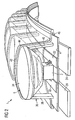
- FIG. 1 shows a schematic representation of a shape-flexible lighting system 1 according to a first embodiment, with a plurality of light-emitting diodes 2 type TOPLED ® .
- the light emitting diodes are designed as surface emitting components and emit in their operation radiation from a side facing away from the respective mounting surface.
- the LEDs are arranged one behind the other on a flexible substrate 4, wherein an optical system 6 is provided, which allows a uniform, directional and / or glare light emission.
- the illumination system 1 has a form-flexible design and emits light directed but without dazzling effect, wherein at the same time the individual light spots of the light-emitting diodes 2 are essentially not recognizable.
- the radiant power emitted by the illumination system thus does not fall off, or at least only weakly, in the region between two adjacent light-emitting diodes 2.
- the lighting system 1 is characterized by a high integration of the LEDs 2 and variability of the lighting options. This results in novel lights that are suitable both for displaying (eg information on screens, traffic signs, advertising space, etc.), marking (backlighting) and for lighting. Due to the small dimensions of the lighting system 1 is still predestined as an installation light. Due to the flexibility, the lighting system 1 can also be used on curved surfaces. Furthermore, the deformation can also be done in free space by the attachment of suitable, not shown devices or kinematics (rods, ropes, tires, etc.).
- the lighting system 1 designed as a flexible, flat light band 8 (light rail) be.
- the luminaire housing as the light-emitting diodes 2 receiving, flexible hollow profile rail 10 is formed with a substantially rectangular cross-section, in which the LEDs 2 are arranged adjacent and form a common luminous surface 12. It is generally advantageous if the light-emitting diodes 2 are colored and / or color-changeable.
- the light-emitting diodes can have a plurality, for example three, light-emitting diode chips which emit radiation in mutually different spectral ranges, for example in the green, blue and red spectral range.
- the lighting system 1 can be equipped with a combination of different light-emitting diodes 2.
- a light rail 8 for example, as an extruded profile of a flexible plastic, such as PMMA, manufacturing technology be made advantageous.
- the light rail 8 can be cut to length depending on the application in divisions (according to the electrical circuit grouping).
- the hollow profile rail 10 is positively in a mounting profile or other holder (not shown) inserted, with projections of the mounting profile or holder in two, preferably opposite , Side surfaces 14, 16 trained guide grooves 18, 20 of the hollow profile rail 10 engage.
- a substrate 4 for the LEDs 2 is in the illustrated embodiment, a printed circuit board 22 provided with flexplate use, so that a flexible lighting system 1 is achieved with an extremely low height of about 6 mm.
- two thin heat sinks 24 are provided with high thermal conductivity on the underside of the flexplate 4. From the illustrated first Deviating example, the attachment can be made on magnetizable surfaces formed by magnets as cooling plates 24 or a magnetic substrate.
- the hollow profile rail 10 has an interior space 26 for receiving the light-emitting diodes 2, which is closable on both sides by an end piece 28 and / or an electrical plug contact 30, 32 (plug 30 or socket 32).
- the lighting system 1 can be easily extended to a light rail of any length.
- the length of the lighting system 1 is thus adjustable by juxtaposing and electrically connecting a plurality of hollow profile rails 10 by means of the plug contacts in a simple and variable manner.
- the end piece 28 or the plug contacts 30, 32 are formed in such a manner that their side surfaces in the mounted on the hollow profile rail 10 state with its side surfaces are flush.
- the end piece 28 and / or the plug contacts 30, 32 are frontally inserted into the rail 8 and held releasably for example by a not shown locking connection in this.
- the optics 6 is formed in this embodiment by a patch on the light emitting diodes 2 rigid lens optics 34 made of glass or plastic. It is particularly advantageous if the lens optics 34 is formed as a separate component, so that the illumination system 1 can be variably adapted to different lighting and lighting tasks by replacing the optics 34. Flexibility is provided in this case by: the rigid optic 6 consists of several individual parts, but whose position is essentially unchanged with respect to the light-emitting diodes 2 during a deformation of the illumination system 1.
- the lenses 32 with a holder 36, which has two diametrically opposed support members 38, 40, supported on the flexplate 4 and a form-fitting encompassing this luminaire cover 42 of laminated laminated films 44, 46 fixed on the light emitting diode 2, wherein the holder 36 and the lamp cover 42 are formed so that they do not obstruct a deformation of the lighting system 1.
- the illumination system 1 is freely alignable and focusable.
- an optically active fluid can be used, whereby due to the different refractive indices between air and fluid, a uniform, directed and / or glare-inducing light effect can be achieved.
- the use of fluids is particularly advantageous if a great deal of flexibility is to be achieved.
- the light-emitting diodes 2 and other electronic components are protected against environmental influences (water, dust, radiation, chemicals, in some cases also external forces) (protection class IP65).
- the cooling plates 24 are also fixed in the lamp cover 42.
- the plug-in system 30, 32 (see FIG. 1 ) preferably also meets the protection class IP65.
- Such a running lighting system can also be used outdoors.
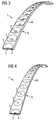
- FIG. 3 shows a second embodiment of an illumination system in which the light rail 8 is carried out further optimized height
- the construction height is preferred 5 mm or less, more preferably 4 mm or less, for example, about 3 mm.
- gorgenminimator LEDs are 2 ® of type PointLED use, arranged on a flexible printed circuit board 4 and are embedded in a casing 48 made of deep-drawn laminated films.
- This solution is characterized in particular by an optics 6 integrated in the foil housing 48 as a microstructure and / or macrostructure, so that it is possible to dispense with further lens systems.
- the microstructured film preferably has a structure with feature sizes of 500 ⁇ m or less, preferably 100 ⁇ m or less, more preferably 10 ⁇ m or less.
- a nanostructured film in particular with structure sizes of 1000 nm or less, can also be used.
- the structure size can be in the range, preferably between 0.2 and 5 times, the emission wavelength of the associated light-emitting diode in the material of the film.
- the radiation characteristic can thus be adjusted for example by means of diffraction effects.
- the structuring of the film can here be regular, in particular periodically recurring along one or more spatial directions, or irregular.
- a further minimization of size is achieved by the use of height-optimized, in particular passive or active electronic, components, in particular height-minimized resistors and / or drivers, in particular foil resistors, hybrid resistors or the like.
- FIG. 4 shows a third embodiment of an illumination system 1, which is again designed minimized.
- the height is preferably 3 mm or less, more preferably 2 mm or less, for example height 1.5 mm.
- This embodiment differs from the above-described embodiment essentially in that the LEDs 2 in this variant directly - ie without housing - are applied to the flex board 4 (COF - Chip on Flexboard).
- the chip-on-flexboard technology is a production technology in microelectronics, in which unhoused semiconductors, for example light-emitting diode chips, are glued directly onto the printed circuit board 4 and then electrically contacted with microwires. Alternatively, the light-emitting diode chips can also be fastened and electrically contacted at least with one contact directly on the printed circuit board. This can be done for example by means of soldering.
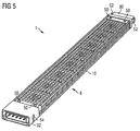
- a light rail 8 is shown, in which on both sides in the approximately rectangular hollow profile rail 10, a 5-pin connector system 30, 32 consisting of a plug 30 and a socket 32 and inserted by means of fasteners 50, such as rivets, screws or in clip art, is fixed.
- the plug 30 are provided for fixing in the socket 32 with locking projections 52 which are inserted and fixed in corresponding recesses 54 of the socket 32 of an adjacent light rail 8.
- a flexible light band consisting of a plurality of light rails 8 can be constructed in a simple manner (plug & play).
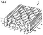
- this fourth embodiment differs from that in FIG. 1 shown essentially in that the light emitting diodes 2 associated optics 6 is formed as a substantially U-shaped, flexible Fresnel lens 56. This is supported on its narrow sides on the flexplate 4 and fixed in the interior 26 of the hollow profile rail 10.
- a cooling plate 24 is arranged with high thermal conductivity under the flexplate 4 to dissipate the waste heat of the light-emitting diodes 2. Due to the thus optimized thermal management, the light output of the lighting system 1 can be further improved with reduced space.
- the hollow profile rail 10 on side surfaces 58, 60, two projections 62, 64, each in a guide groove 66, 68 of a mounting profile 70 engage, so that the hollow profile rail 10 is positively inserted into the mounting profile 70.
- the cooling plate 24 or the mounting surface is magnetically formed.
- the mounting profile 70 is substantially U-shaped and provided on its narrow sides with a respective groove 72, 74, in which an approximately U-shaped, fixedly arranged holder 76 for fixing the lighting system 1 positively intervenes.
- the plug-in system is provided with a connecting cable 78.
- FIG. 8 shows a sixth embodiment in which the hollow profile rail 10 for fixing the lighting system 1, for example, on a ceiling, the floor, the wall or a piece of furniture directly, that is fixed longitudinally displaceable and flexibly flexible without mounting profile 70 in a provided with a closure bracket 80 retaining clip 82 is.
- a plurality of spaced-apart retaining clips 82 are used for fastening the lighting system 1 use.
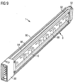
- FIG. 9 shows a seventh embodiment of a light rail 8, in the side, in the direction of a narrow side 84 of the illumination system 1 emitting LEDs 2 type SIDELED ® are used.
- Such light rails 8 require extremely little space and are for fastening the lighting system 1, for example on a ceiling, the floor, the wall or a piece of furniture, two provided on side surfaces 86, 88 of the hollow profile rail 10 projections 90, 92, according to FIG. 10 in each case a guide groove 94, 96 of a mounting profile 98 engage, positively in the mounting profile 98 can be inserted.
- the mounting profile 98 with a substantially U-shaped cross-section is provided on its broad sides, each with a groove 100, 102, in which an approximately U-shaped stationary trained holder 76 for fixing the illumination system 1 engages positively.
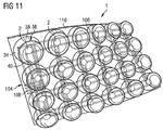
- the lighting system 1 as a flexible, pixel-like flat lamp 104 with a plurality of light-emitting diodes 2 may be formed.
- the flat lamp 104 may be designed as a display, for example for moving images, or as a flat lamp 104 for a spherically curved luminaire or a headliner in vehicle technology.
- the light-emitting diodes 2 are applied in a matrix-like manner to a highly flexible foil conductor 106 and are electrically contacted by conductor tracks 108.
- the light emitting diodes 2 are preferably individually controllable via a drive device, not shown, in particular via a bus, so that different light effects, such as light colors, accents, light dynamics or optical representations can be realized. It is generally advantageous if the light-emitting diodes 2 are colored and / or color-changeable. For example, the light-emitting diodes may have different light-emitting diode chips which emit radiation in mutually different spectral regions. With light-emitting diodes, in which the intensity of the emitted radiation in the red, green and blue spectral range can be set separately, a full-color, active display device can be formed in a simplified manner.
- the lighting system 1 can be equipped with a combination of different light-emitting diodes 2.
- the optics 6 is formed by a respective, the light-emitting diodes 2 superior rigid lens optics 34 made of glass, which is designed as a separate component, so that the illumination system 1 can be adjusted by replacing the optics 34 variably to different lighting and lighting tasks.
- the flexibility is provided by the lenses 32 being supported on the foil conductor 106 by means of a holder 36 made of two support elements 38, 40 disposed diametrically opposite one another, and by a foil 110 engaging around the latter in a form-fitting manner nubs are fixed on the film conductor 106, wherein the holder 36 and the film conductor 106 are formed so that they do not obstruct a deformation of the lighting system 1.
- the illumination system 1 is freely alignable and focusable.
- the film 110 and the film conductor 106 the light-emitting diodes 2 and other electronic components from environmental influences (water, dust, radiation, chemicals, sometimes even external forces) protected (protection class IP65).
- Such a flat lamp 104 or such a flat display is suitable for application to curved surfaces with, even several, parallel or obliquely extending axes of curvature with different, even negative, bending radii.
- the flat lamp 104 can be cut into individual rectangles and can be further electrically connected via connecting elements, not shown, for example, connection crosses.
- the individual lenses 34 can furthermore be connected to each other quasi-elastically, for example via a web or an expanded metal mesh.
- the lens system is also applicable to a light-emitting diode array with different light diode divisions.
- the lighting system 1 is not limited to the illustrated embodiments, but the lighting systems 1 may have different shapes. As already explained at the outset, the illustrated light rails 8 and flat lamps 104 can be arbitrarily varied and combined on account of the dimensionally flexible, modular character of the lighting system 1.
- a formflexibles lighting system 1 with at least one light emitting diode 2, which on a flexible Support material 4 is arranged, wherein an optic 6 is provided, which allows a uniform, directed and / or glare light emission.
Landscapes
- Engineering & Computer Science (AREA)
- General Engineering & Computer Science (AREA)
- Physics & Mathematics (AREA)
- General Physics & Mathematics (AREA)
- Theoretical Computer Science (AREA)
- Non-Portable Lighting Devices Or Systems Thereof (AREA)
- Illuminated Signs And Luminous Advertising (AREA)
- Securing Globes, Refractors, Reflectors Or The Like (AREA)
- Led Device Packages (AREA)
- Arrangement Of Elements, Cooling, Sealing, Or The Like Of Lighting Devices (AREA)
Claims (13)
- Système d'éclairage (1) à flexibilité de forme, comprenant au moins une diode électroluminescente (2) qui est disposée sur un matériau porteur (4) flexible, une optique (6) étant prévue, laquelle permet un rayonnement de lumière régulier, dirigé et/ou anti-éblouissement, l'optique (6) étant réalisée sous la forme d'un élément structural séparé, caractérisé en ce que l'optique est interchangeable.
- Système d'éclairage à flexibilité de forme selon la revendication 1, l'optique (6) étant une optique à lentille (34).
- Système d'éclairage à flexibilité de forme selon la revendication 2, l'optique (6) étant une lentille de Fresnel (56).
- Système d'éclairage à flexibilité de forme selon l'une des revendications précédentes, l'optique (6) possédant une macrostructure.
- Système d'éclairage à flexibilité de forme selon l'une des revendications précédentes, l'optique (6) possédant des grosseurs, des ondes, des boutons ou similaires.
- Système d'éclairage à flexibilité de forme selon l'une des revendications précédentes, l'optique (6) possédant un milieu à action optique.
- Système d'éclairage à flexibilité de forme selon l'une des revendications précédentes, l'optique (6) possédant un fluide à action optique.
- Système d'éclairage à flexibilité de forme selon l'une des revendications 1 à 6, l'optique (6) possédant un film.
- Système d'éclairage à flexibilité de forme selon l'une des revendications précédentes, l'optique (6) étant fabriquée dans un matériau rigide.
- Système d'éclairage à flexibilité de forme selon l'une des revendications précédentes, l'optique (6) étant fabriquée en verre.
- Système d'éclairage à flexibilité de forme selon l'une des revendications précédentes, l'optique (6) étant maintenue par le biais d'un support (36) de telle sorte qu'elle n'empêche pas une déformation du système d'éclairage (1).
- Système d'éclairage à flexibilité de forme selon la revendication 11, le support (36) possédant au moins deux éléments d'appui (38, 40), de préférence disposés diamétralement l'un par rapport à l'autre, et s'appuyant sur le matériau porteur (4) par le biais de ceux-ci.
- Système d'éclairage à flexibilité de forme selon l'une des revendications précédentes, l'optique (6) étant montée de telle sorte que sa position par rapport à la diode électroluminescente (2) reste sensiblement inchangée pendant une déformation du système d'éclairage (1).
Applications Claiming Priority (2)
| Application Number | Priority Date | Filing Date | Title |
|---|---|---|---|
| DE102006031345A DE102006031345A1 (de) | 2006-07-06 | 2006-07-06 | Formflexibles Beleuchtungssystem |
| PCT/DE2007/001139 WO2008003289A2 (fr) | 2006-07-06 | 2007-06-27 | Système d'éclairage flexible |
Publications (2)
| Publication Number | Publication Date |
|---|---|
| EP2041483A2 EP2041483A2 (fr) | 2009-04-01 |
| EP2041483B1 true EP2041483B1 (fr) | 2016-10-05 |
Family
ID=38476186
Family Applications (1)
| Application Number | Title | Priority Date | Filing Date |
|---|---|---|---|
| EP07785572.4A Active EP2041483B1 (fr) | 2006-07-06 | 2007-06-27 | Système d'éclairage flexible |
Country Status (6)
| Country | Link |
|---|---|
| US (2) | US8360608B2 (fr) |
| EP (1) | EP2041483B1 (fr) |
| CN (1) | CN101535710B (fr) |
| DE (1) | DE102006031345A1 (fr) |
| TW (1) | TW200811398A (fr) |
| WO (1) | WO2008003289A2 (fr) |
Families Citing this family (127)
| Publication number | Priority date | Publication date | Assignee | Title |
|---|---|---|---|---|
| DE102008003638B4 (de) * | 2008-01-09 | 2010-03-04 | Continental Automotive Gmbh | Anzeigevorrichtung |
| DE102008013454B4 (de) * | 2008-03-10 | 2012-05-31 | Vossloh-Schwabe Optoelectronic Gmbh & Co. Kg | LED-Baueinheit für Beleuchtungszwecke |
| US9228732B2 (en) | 2008-07-08 | 2016-01-05 | Us Vaopto, Inc. | Modular LED lighting systems, including flexible, rigid, and waterproof lighting strips and connectors |
| DE102009020851A1 (de) * | 2009-05-12 | 2010-11-25 | Osram Gesellschaft mit beschränkter Haftung | Leuchtband und Verfahren zum Herstellen eines Leuchtbands |
| JP5442317B2 (ja) * | 2009-05-14 | 2014-03-12 | 株式会社小糸製作所 | 車両用灯具 |
| DE102009021846A1 (de) * | 2009-05-19 | 2010-12-30 | Osram Gesellschaft mit beschränkter Haftung | Stromversorgungsmodul und Leuchtband |
| DE102009036122B4 (de) * | 2009-08-05 | 2011-07-21 | BJB GmbH & Co. KG, 59755 | Lampensockel und Lampenfassung |
| US9177492B2 (en) * | 2010-01-25 | 2015-11-03 | Gt Biomescilt Light Limited | Flexible LED display screens |
| US8662705B2 (en) * | 2010-03-30 | 2014-03-04 | Virwall Systems, Inc. | Flexible ultraviolet LED sanitizing apparatus |
| DE102010016385B4 (de) * | 2010-04-09 | 2014-11-06 | Selux Aktiengesellschaft | Beleuchtungsanordnung mit Leuchtdioden |
| DE102010014520A1 (de) * | 2010-04-09 | 2011-10-13 | Christian Bartenbach | Leuchte |
| KR101641860B1 (ko) * | 2010-05-12 | 2016-07-29 | 엘지이노텍 주식회사 | 발광소자 어레이, 조명장치 및 백라이트 장치 |
| US9033542B2 (en) | 2010-11-16 | 2015-05-19 | Dialight Corporation | LED luminaire utilizing an extended and non-metallic enclosure |
| US9797560B2 (en) * | 2010-11-16 | 2017-10-24 | Dialight Corporation | LED luminaire utilizing an extended and non-metallic enclosure |
| US9822951B2 (en) | 2010-12-06 | 2017-11-21 | Cree, Inc. | LED retrofit lens for fluorescent tube |
| US10309627B2 (en) | 2012-11-08 | 2019-06-04 | Cree, Inc. | Light fixture retrofit kit with integrated light bar |
| US8637880B2 (en) * | 2010-12-22 | 2014-01-28 | E.I. Du Pont De Nemours And Company | Three dimensional light emitting diode systems, and compositions and methods relating thereto |
| US8629464B2 (en) * | 2010-12-22 | 2014-01-14 | E. I. Du Pont De Nemours And Company | Three dimensional light emitting diode systems, and compositions and methods relating thereto |
| DE102011002849A1 (de) | 2011-01-19 | 2012-07-19 | Ridi - Leuchten Gmbh | Elektrischer Verbinder |
| US9395057B2 (en) * | 2011-02-07 | 2016-07-19 | Cree, Inc. | Lighting device with flexibly coupled heatsinks |
| DE102011001680A1 (de) * | 2011-03-30 | 2012-10-04 | W. Döllken & Co. GmbH | Verfahren zum Herstellen eines Beleuchtungskörpers auf LED-Basis |
| US8845129B1 (en) * | 2011-07-21 | 2014-09-30 | Cooper Technologies Company | Method and system for providing an array of modular illumination sources |
| CA142030S (en) * | 2011-08-31 | 2014-07-04 | Knog Pty Ltd | Portable light |
| DE102011082490A1 (de) * | 2011-09-12 | 2013-03-14 | Siemens Aktiengesellschaft | Lichtprofilschlauch |
| KR20130033743A (ko) * | 2011-09-27 | 2013-04-04 | 삼성디스플레이 주식회사 | 백라이트 어셈블리용 광원 및 이를 포함하는 백라이트 어셈블리 |
| TWI461629B (zh) * | 2012-02-01 | 2014-11-21 | 台達電子工業股份有限公司 | 照明裝置及其照明模組 |
| CN102588921A (zh) * | 2012-02-08 | 2012-07-18 | 深圳市泓亚光电子有限公司 | 灯具散热器及热磁散热led路灯 |
| US9117991B1 (en) * | 2012-02-10 | 2015-08-25 | Flextronics Ap, Llc | Use of flexible circuits incorporating a heat spreading layer and the rigidizing specific areas within such a construction by creating stiffening structures within said circuits by either folding, bending, forming or combinations thereof |
| DK177534B1 (en) * | 2012-03-21 | 2013-09-08 | Martin Professional As | Flexible led pixel string with two shielding ground lines |
| TWI591380B (zh) * | 2012-04-16 | 2017-07-11 | 佛塞安科技公司 | 光源裝置、照明系統及發出光線的方法 |
| JP6166104B2 (ja) * | 2012-06-08 | 2017-07-19 | エルジー イノテック カンパニー リミテッド | ランプユニット及びそれを用いた車両 |
| US9194566B2 (en) * | 2012-06-08 | 2015-11-24 | Lg Innotek Co., Ltd. | Lamp unit and vehicle lamp apparatus using the same |
| EP2685157A3 (fr) * | 2012-07-09 | 2014-02-12 | Ferdinand Pfleghart | Lampe à profil DEL étanche |
| US9482396B2 (en) * | 2012-11-08 | 2016-11-01 | Cree, Inc. | Integrated linear light engine |
| US9441818B2 (en) | 2012-11-08 | 2016-09-13 | Cree, Inc. | Uplight with suspended fixture |
| US10788176B2 (en) | 2013-02-08 | 2020-09-29 | Ideal Industries Lighting Llc | Modular LED lighting system |
| US9494304B2 (en) | 2012-11-08 | 2016-11-15 | Cree, Inc. | Recessed light fixture retrofit kit |
| KR102080610B1 (ko) | 2012-11-14 | 2020-02-25 | 엘지이노텍 주식회사 | 램프 및 그를 이용한 차량 램프 장치 |
| US9874333B2 (en) | 2013-03-14 | 2018-01-23 | Cree, Inc. | Surface ambient wrap light fixture |
| US10584860B2 (en) | 2013-03-14 | 2020-03-10 | Ideal Industries, Llc | Linear light fixture with interchangeable light engine unit |
| CN105142682B (zh) * | 2013-03-18 | 2019-06-21 | 传感器电子技术股份有限公司 | 柔性紫外线装置 |
| US9844608B2 (en) * | 2013-03-18 | 2017-12-19 | Sensor Electronic Technology, Inc. | Flexible ultraviolet device |
| US20140313722A1 (en) * | 2013-04-17 | 2014-10-23 | Raw Thrills, Inc. | Flexible Decorative Lighted Strip, Cabinet Including Same, and Installation Method |
| DE102013007641A1 (de) * | 2013-05-06 | 2014-11-06 | Paulmann Licht Gmbh | Beleuchtungsanordnung |
| US9041021B2 (en) * | 2013-06-14 | 2015-05-26 | Shanghai Huan Hsin Electronics Co., Ltd. | LED light assembly |
| US10240765B2 (en) | 2013-07-25 | 2019-03-26 | Abl Research Group, Llc | Arc modular light devices, systems, and methods |
| US9461024B2 (en) | 2013-08-01 | 2016-10-04 | Cree, Inc. | Light emitter devices and methods for light emitting diode (LED) chips |
| CN105659310B (zh) | 2013-08-13 | 2021-02-26 | 飞利斯有限公司 | 电子显示区域的优化 |
| WO2015031501A1 (fr) * | 2013-08-27 | 2015-03-05 | Polyera Corporation | Dispositif pouvant être attaché ayant un composant électronique souple |
| WO2015031426A1 (fr) | 2013-08-27 | 2015-03-05 | Polyera Corporation | Affichage flexible et détection d'état de flexibilité |
| WO2015038684A1 (fr) | 2013-09-10 | 2015-03-19 | Polyera Corporation | Article à attacher comportant une signalisation, un affichage divisé et des fonctionnalités de messagerie |
| US9835308B2 (en) * | 2013-10-08 | 2017-12-05 | Combustion And Energy S.R.L. | Light indicator |
| US10900653B2 (en) | 2013-11-01 | 2021-01-26 | Cree Hong Kong Limited | LED mini-linear light engine |
| US9869456B2 (en) * | 2013-11-08 | 2018-01-16 | Osram Sylvania Inc. | Fixture design for flexible LED circuit boards |
| US10612747B2 (en) | 2013-12-16 | 2020-04-07 | Ideal Industries Lighting Llc | Linear shelf light fixture with gap filler elements |
| US10100988B2 (en) | 2013-12-16 | 2018-10-16 | Cree, Inc. | Linear shelf light fixture with reflectors |
| EP3087560B9 (fr) | 2013-12-24 | 2021-08-11 | Flexterra, Inc. | Structures de support pour composant électronique flexible |
| KR20160103083A (ko) | 2013-12-24 | 2016-08-31 | 폴리에라 코퍼레이션 | 탈부착형 2차원 플렉서블 전자 기기용 지지 구조물 |
| TWI676880B (zh) | 2013-12-24 | 2019-11-11 | 美商飛利斯有限公司 | 動態可撓物品 |
| WO2015100224A1 (fr) | 2013-12-24 | 2015-07-02 | Polyera Corporation | Dispositif d'affichage électronique souple ayant une interface utilisateur basée sur des mouvements détectés |
| EP2902697B1 (fr) * | 2014-02-03 | 2018-07-04 | CINI & NILLS S.r.l. | Dispositif d'éclairage formé de bande d'élement d'éclairage avec un couplage magnétique |
| US20150227245A1 (en) | 2014-02-10 | 2015-08-13 | Polyera Corporation | Attachable Device with Flexible Electronic Display Orientation Detection |
| US9555610B2 (en) | 2014-03-10 | 2017-01-31 | Forever Bulb, Llc | LED light bulb with internal flexible heatsink and circuit |
| US10261634B2 (en) * | 2014-03-27 | 2019-04-16 | Flexterra, Inc. | Infrared touch system for flexible displays |
| USD757324S1 (en) | 2014-04-14 | 2016-05-24 | Cree, Inc. | Linear shelf light fixture with reflectors |
| EP2933551B1 (fr) * | 2014-04-15 | 2017-06-14 | OSRAM GmbH | Dispositif d'éclairage et un procédé correspondant |
| US9702531B2 (en) | 2014-04-23 | 2017-07-11 | General Led, Inc. | Retrofit system and method for replacing linear fluorescent lamp with LED modules |
| WO2015184045A2 (fr) | 2014-05-28 | 2015-12-03 | Polyera Corporation | Dispositif comportant des composants électroniques souples sur plusieurs surfaces |
| WO2015184458A1 (fr) * | 2014-05-30 | 2015-12-03 | Osram Sylvania Inc. | Moteurs de gestion d'éclairage intégrés comprenant des dispositifs optiques souples et des sources de lumière souples |
| EP3152477B1 (fr) * | 2014-05-30 | 2020-03-18 | Lumileds Holding B.V. | Dels montées sur un châssis de brochage incurvé |
| CN104064124B (zh) * | 2014-07-10 | 2018-02-02 | 刘延平 | 一种拼接精密的可折叠led屏幕 |
| US9285098B2 (en) * | 2014-07-21 | 2016-03-15 | CoreLed Systems, LLC | LED luminaire |
| CN106662318A (zh) * | 2014-08-29 | 2017-05-10 | 飞利浦灯具控股公司 | 照明模块和外壳 |
| CN104332114B (zh) * | 2014-11-04 | 2017-10-31 | 深圳金立翔视效科技有限公司 | 可弯曲led模组、圆形led模组以及波浪形led模组 |
| KR20160056087A (ko) * | 2014-11-11 | 2016-05-19 | 엘지이노텍 주식회사 | 발광 장치 |
| WO2016138356A1 (fr) | 2015-02-26 | 2016-09-01 | Polyera Corporation | Dispositif pouvant être attaché, pourvu d'un composant électronique souple |
| DE102015204057B4 (de) * | 2015-03-06 | 2024-12-12 | Inventronics Gmbh | Herstellen eines Beleuchtungsmoduls |
| US10145552B2 (en) * | 2015-03-26 | 2018-12-04 | Lux Lighting Systems, Llc | Magnetic light emitting diode (LED) lighting system |
| USD814094S1 (en) * | 2015-04-13 | 2018-03-27 | Electronic Controls Company | LED optic |
| US9841152B2 (en) * | 2015-06-02 | 2017-12-12 | Damian L. Stafford | Traffic control light strip |
| JP6688496B2 (ja) * | 2015-06-16 | 2020-04-28 | トライト株式会社 | フレキシブル発光モジュール、及び、フレキシブル発光モジュールの製造方法 |
| US10036531B2 (en) | 2015-09-08 | 2018-07-31 | CoreLed Systems, LLC | Camera flash with fresnel optic |
| EP3163160A1 (fr) | 2015-10-28 | 2017-05-03 | Sebastian Mayer | Dispositif de representation d'image |
| DE102015221938A1 (de) * | 2015-11-09 | 2017-05-11 | Robert Bosch Gmbh | Beleuchtungseinheit |
| DE102015122510A1 (de) * | 2015-12-22 | 2017-06-22 | Rehau Ag + Co | Leuchtvorrichtung mit einer länglichen Leuchte und einem Schutzelement aus einem Kunststoffmaterial |
| US10352510B2 (en) * | 2015-12-28 | 2019-07-16 | ETi Solid State Lighting Inc. | Linkable lighting fixture |
| DE202016100615U1 (de) * | 2016-02-08 | 2017-05-09 | Zumtobel Lighting Gmbh | Leuchtenoptik, Leuchtenoptiksystem sowie Leuchte mit Leuchtenoptik |
| DE102016102292B4 (de) * | 2016-02-10 | 2017-10-05 | Insta Gmbh | Beleuchtungseinrichtung |
| US9537274B1 (en) * | 2016-02-16 | 2017-01-03 | Elemental LED, Inc. | Modular power and connector system for lighting elements |
| DE102016003733A1 (de) * | 2016-03-22 | 2017-05-04 | Diehl Aerospace Gmbh | Leuchtmodul, Leuchte und Leuchtmodulsatz |
| CN107228298A (zh) * | 2016-03-23 | 2017-10-03 | 丽盟有限公司 | 发光结构与具有该发光结构的时钟 |
| US9995445B2 (en) * | 2016-05-17 | 2018-06-12 | Tang-Hao Chien | Lighting system having improved unidirectional intensity |
| US10234087B2 (en) * | 2016-07-01 | 2019-03-19 | BeDazzleLit LLC | Personal mobility assistance devices with light sets and methods |
| FR3056705B1 (fr) * | 2016-09-28 | 2020-07-24 | Valeo Vision | Module d'emission lumineuse a commande amelioree notamment pour vehicule automobile |
| WO2018076029A1 (fr) * | 2016-10-13 | 2018-04-26 | Ncm Innovations (Pty) Ltd | Filet de sécurité éclairant |
| US11585501B2 (en) | 2016-10-20 | 2023-02-21 | Axis Lighting Inc. | Couplers for light fixtures |
| US10215380B2 (en) | 2016-10-20 | 2019-02-26 | Axis Lighting Inc. | Couplers for light fixtures |
| USD1088336S1 (en) | 2016-10-20 | 2025-08-12 | Axis Lighting Inc. | Light fixture |
| US12085258B2 (en) | 2016-10-20 | 2024-09-10 | Axis Lighting Inc. | Couplers for light fixtures |
| US10219570B2 (en) * | 2016-11-18 | 2019-03-05 | Thomas H. Scott | Flexible lighting apparatus with adhesive for mounting to helmet outer surface |
| US10195985B2 (en) * | 2017-03-08 | 2019-02-05 | Ford Global Technologies, Llc | Vehicle light system |
| DE102017108113A1 (de) | 2017-04-13 | 2018-10-18 | Rzb Rudolf Zimmermann, Bamberg Gmbh | Mehrfachlinsenanordnung für eine Beleuchtungsvorrichtung |
| US11199002B2 (en) | 2017-07-14 | 2021-12-14 | Axis Lighting Inc. | Acoustic panel |
| US10731804B2 (en) * | 2018-01-24 | 2020-08-04 | Carl Boehmer | Traffic control system with flexible LED lighted assembly |
| US10443823B2 (en) | 2018-01-31 | 2019-10-15 | Axis Lighting Inc. | Mount interace for light fixtures |
| US11384927B2 (en) | 2018-01-31 | 2022-07-12 | Axis Lighting Inc. | Conduit access for light fixtures |
| JP6773713B2 (ja) * | 2018-03-29 | 2020-10-21 | ファナック株式会社 | ロボットシステム |
| IT201800007704A1 (it) | 2018-07-31 | 2020-01-31 | Teleco Automation Srl | Dispositivo di illuminazione perfezionato |
| US20200049329A1 (en) * | 2018-08-08 | 2020-02-13 | General lighting Electronic Co.,Ltd | Led strip that can be bent in three-dimensional space |
| US10847701B2 (en) * | 2018-09-18 | 2020-11-24 | Aura Technologies, Llc | Semi-flexible lighting module |
| US12613018B2 (en) * | 2019-02-21 | 2026-04-28 | HELLA GmbH & Co. KGaA | Lighting device, in particular lighting device for a vehicle |
| CN110578878B (zh) * | 2019-09-20 | 2025-03-07 | 深圳市彬赢光电有限公司 | 带透镜的柔性灯条及其制造方法 |
| CN110778984A (zh) * | 2019-11-19 | 2020-02-11 | 华域视觉科技(上海)有限公司 | Led总成和低成本省空间曲线状信号灯 |
| CN111055973A (zh) * | 2019-12-11 | 2020-04-24 | 澳龙船艇科技有限公司 | 船舶亮化方法和结构 |
| WO2021142350A1 (fr) | 2020-01-09 | 2021-07-15 | Electronic Controls Company | Feu d'avertissement de véhicule directionnel flexible |
| USD1010179S1 (en) | 2020-01-09 | 2024-01-02 | Electronic Controls Company | Flexible directional vehicle warning light |
| KR102409789B1 (ko) * | 2020-04-29 | 2022-06-20 | 케이에이치필룩스 주식회사 | 조명장치 및 이를 구비하는 조명시스템 |
| FI20206146A1 (fi) | 2020-11-12 | 2022-05-13 | Teknoware Oy | Ledinauha ja menetelmä ledinauhan valmistamiseksi |
| US20240050612A1 (en) * | 2021-03-15 | 2024-02-15 | Shanghai Sansi Electronic Engineering Co. Ltd. | Led package structure, and disinfection device and disinfection lamp applying same |
| US11679171B2 (en) | 2021-06-08 | 2023-06-20 | Steribin, LLC | Apparatus and method for disinfecting substances as they pass through a pipe |
| WO2023012507A1 (fr) * | 2021-08-06 | 2023-02-09 | Stepan Engineering Gmbh | Technique de liaison de connexion pour un système de profilé de del, et système de profilé de del |
| DE102022126489A1 (de) * | 2022-10-12 | 2024-04-18 | HELLA GmbH & Co. KGaA | Anordnung aus zwei Leuchten und einem Lichtband einer Kraftfahrzeugaußenbeleuchtung |
| FR3141230B1 (fr) * | 2022-10-25 | 2025-01-10 | Valeo Vision | Dispositif optique pour un dispositif lumineux de signalisation |
| WO2025051748A1 (fr) * | 2023-09-04 | 2025-03-13 | Valeo Vision | Module optique, appareil de lampe et véhicule à moteur |
| US12320493B1 (en) * | 2023-11-17 | 2025-06-03 | Juluen Enterprise Co., Ltd. | Flexible warning light |
| IT202400003031A1 (it) * | 2024-02-13 | 2025-08-13 | Linea Light S R L | Apparecchio d’illuminazione lineare e relativo metodo di realizzazione |
| US20260063254A1 (en) * | 2024-08-30 | 2026-03-05 | Celebright Inc. | Integrated switching power supply in light string for permanent holiday lighting systems |
Family Cites Families (22)
| Publication number | Priority date | Publication date | Assignee | Title |
|---|---|---|---|---|
| US4924362A (en) * | 1986-08-15 | 1990-05-08 | Alliko Unlimited Corporation | Illuminated article and waterproof illuminated harness |
| US5128843A (en) * | 1991-05-13 | 1992-07-07 | Guritz Steven P W | Multipurpose optical display for articulating surfaces |
| US5404869A (en) * | 1992-04-16 | 1995-04-11 | Tir Technologies, Inc. | Faceted totally internally reflecting lens with individually curved faces on facets |
| US5890794A (en) * | 1996-04-03 | 1999-04-06 | Abtahi; Homayoon | Lighting units |
| DE19621148A1 (de) * | 1996-05-14 | 1997-12-04 | Magna Reflex Holding Gmbh | Leuchtelement |
| DE19627856A1 (de) * | 1996-07-11 | 1998-01-15 | Happich Fahrzeug & Ind Teile | Beleuchtungsleiste und Verfahren zur Herstellung |
| DE19909399C1 (de) | 1999-03-04 | 2001-01-04 | Osram Opto Semiconductors Gmbh | Flexibles LED-Mehrfachmodul, insb. für ein Leuchtengehäuse eines Kraftfahrzeuges |
| US6520669B1 (en) * | 2000-06-19 | 2003-02-18 | Light Sciences Corporation | Flexible substrate mounted solid-state light sources for exterior vehicular lighting |
| US6891200B2 (en) * | 2001-01-25 | 2005-05-10 | Matsushita Electric Industrial Co., Ltd. | Light-emitting unit, light-emitting unit assembly, and lighting apparatus produced using a plurality of light-emitting units |
| JP4067802B2 (ja) | 2001-09-18 | 2008-03-26 | 松下電器産業株式会社 | 照明装置 |
| US20030147253A1 (en) | 2002-02-06 | 2003-08-07 | Jack Shy | Curved warning light device for attaching to vehicle |
| US6851832B2 (en) * | 2002-05-21 | 2005-02-08 | Dwayne A. Tieszen | Led tube light housings |
| US8322883B2 (en) | 2003-02-04 | 2012-12-04 | Ilight Technologies, Inc. | Flexible illumination device for simulating neon lighting |
| DE10332771A1 (de) * | 2003-07-17 | 2005-03-03 | Marco Schmidt | Bestrahlungs-Handgerät |
| US7128438B2 (en) * | 2004-02-05 | 2006-10-31 | Agilight, Inc. | Light display structures |
| CN2677740Y (zh) | 2004-02-11 | 2005-02-09 | 林原 | 半导体霓虹灯管 |
| US7213941B2 (en) * | 2004-04-14 | 2007-05-08 | Sloanled, Inc. | Flexible perimeter lighting apparatus |
| CN100383455C (zh) | 2004-04-22 | 2008-04-23 | 中国科学院上海光学精密机械研究所 | 可控发光二极管舞台灯 |
| US20060087866A1 (en) * | 2004-10-22 | 2006-04-27 | Ng Kee Y | LED backlight |
| TWI274215B (en) * | 2005-08-10 | 2007-02-21 | Ind Tech Res Inst | Direct type backlight module |
| TWI276894B (en) * | 2005-08-17 | 2007-03-21 | Au Optronics Corp | Backlight unit and light guide plate within and method for diminishing corner shadow area |
| JP2009528685A (ja) * | 2006-09-12 | 2009-08-06 | ポール・ロ | 一体的に成形された一体成形発光ダイオードライトワイヤ |
-
2006
- 2006-07-06 DE DE102006031345A patent/DE102006031345A1/de not_active Withdrawn
-
2007
- 2007-06-27 EP EP07785572.4A patent/EP2041483B1/fr active Active
- 2007-06-27 US US12/306,966 patent/US8360608B2/en not_active Expired - Fee Related
- 2007-06-27 WO PCT/DE2007/001139 patent/WO2008003289A2/fr not_active Ceased
- 2007-06-27 CN CN200780031187.XA patent/CN101535710B/zh active Active
- 2007-07-04 TW TW096124284A patent/TW200811398A/zh unknown
-
2013
- 2013-01-24 US US13/748,952 patent/US8974084B2/en active Active
Also Published As
| Publication number | Publication date |
|---|---|
| WO2008003289A3 (fr) | 2008-03-13 |
| US8360608B2 (en) | 2013-01-29 |
| EP2041483A2 (fr) | 2009-04-01 |
| US20130135855A1 (en) | 2013-05-30 |
| TW200811398A (en) | 2008-03-01 |
| CN101535710A (zh) | 2009-09-16 |
| CN101535710B (zh) | 2016-10-26 |
| US20120182755A1 (en) | 2012-07-19 |
| DE102006031345A1 (de) | 2008-01-10 |
| US8974084B2 (en) | 2015-03-10 |
| WO2008003289A2 (fr) | 2008-01-10 |
Similar Documents
| Publication | Publication Date | Title |
|---|---|---|
| EP2041483B1 (fr) | Système d'éclairage flexible | |
| DE102017124429B4 (de) | Beleuchtungsvorrichtung, Verfahren zur Herstellung einer Beleuchtungsvorrichtung und Lichtverteiler | |
| EP1033525B1 (fr) | Système flexible à diodes électroluminescentes , notamment pour un boîtier de lampe du véhicule | |
| DE112011101270T5 (de) | Niedrigprofil-Extrusion | |
| EP1923626B1 (fr) | Module DEL avec commande intégrée | |
| DE102007043903A1 (de) | Leucht-Vorrichtung | |
| DE102007023651A1 (de) | Beleuchtungseinrichtung, Hinterleuchtungsvorrichtung und Anzeigevorrichtung | |
| DE102009022723A1 (de) | Von rückwärts anzubringendes Leuchtdioden-Modul für Kombinationsrücklichter an Kraftfahrzeugen | |
| DE202011003828U1 (de) | Leuchte für eine Deckenbeleuchtung eines Tunnels | |
| WO2009033477A1 (fr) | Dispositif d'éclairage | |
| DE102012212925A1 (de) | Linsenhalter für LEDs | |
| DE112021005453T5 (de) | LED-Optiksystem | |
| DE102005019018A1 (de) | Leuchte mit wenigstens einem Lichtleiter und mehreren Lichtquellen | |
| EP3353581B1 (fr) | Couche optique et luminaire comprenant une telle couche | |
| DE102013108248A1 (de) | Beleuchtungssystem, insbesondere für einen Kraftfahrzeugscheinwerfer mit einem Kühlkörper | |
| DE102023107164A1 (de) | Eigenständig beleuchtete Vorderwand für ein Fahrzeug | |
| EP2834080B1 (fr) | Plaque en verre composite avec un élément fonctionnel | |
| DE102008016675B4 (de) | Leuchtanordnung mit einem Lichtleiter und Leuchtdioden | |
| AT13039U1 (de) | Reflektoreinheit für leds, led lichtquelle, poster-box sowie verfahren zur montage der led lichtquelle | |
| EP3353582B1 (fr) | Film optique et luminaire comprenant un tel film | |
| EP0978683A1 (fr) | Dispositif d'affichage optique | |
| WO2016096608A1 (fr) | Support à del muni d'une del et lampe munie d'un tel support à del | |
| DE202010005819U1 (de) | Beleuchtungseinrichtung eines Kraftfahrzeugs | |
| DE102014200606A1 (de) | Beleuchtetes Fensterelement | |
| EP2058582B1 (fr) | Lampe à DEL |
Legal Events
| Date | Code | Title | Description |
|---|---|---|---|
| PUAI | Public reference made under article 153(3) epc to a published international application that has entered the european phase |
Free format text: ORIGINAL CODE: 0009012 |
|
| 17P | Request for examination filed |
Effective date: 20090204 |
|
| AK | Designated contracting states |
Kind code of ref document: A2 Designated state(s): AT BE BG CH CY CZ DE DK EE ES FI FR GB GR HU IE IS IT LI LT LU LV MC MT NL PL PT RO SE SI SK TR |
|
| AX | Request for extension of the european patent |
Extension state: AL BA HR MK RS |
|
| DAX | Request for extension of the european patent (deleted) | ||
| RAP1 | Party data changed (applicant data changed or rights of an application transferred) |
Owner name: OSRAM AG |
|
| 17Q | First examination report despatched |
Effective date: 20130103 |
|
| RAP1 | Party data changed (applicant data changed or rights of an application transferred) |
Owner name: OSRAM GMBH |
|
| RAP1 | Party data changed (applicant data changed or rights of an application transferred) |
Owner name: OSRAM GMBH |
|
| GRAP | Despatch of communication of intention to grant a patent |
Free format text: ORIGINAL CODE: EPIDOSNIGR1 |
|
| RIC1 | Information provided on ipc code assigned before grant |
Ipc: F21S 4/00 20160101AFI20160302BHEP Ipc: F21Y 103/00 20160101ALI20160302BHEP Ipc: F21S 4/20 20160101ALI20160302BHEP Ipc: G09F 9/30 20060101ALI20160302BHEP Ipc: F21V 5/04 20060101ALI20160302BHEP |
|
| INTG | Intention to grant announced |
Effective date: 20160318 |
|
| GRAP | Despatch of communication of intention to grant a patent |
Free format text: ORIGINAL CODE: EPIDOSNIGR1 |
|
| INTG | Intention to grant announced |
Effective date: 20160601 |
|
| GRAS | Grant fee paid |
Free format text: ORIGINAL CODE: EPIDOSNIGR3 |
|
| GRAA | (expected) grant |
Free format text: ORIGINAL CODE: 0009210 |
|
| AK | Designated contracting states |
Kind code of ref document: B1 Designated state(s): AT BE BG CH CY CZ DE DK EE ES FI FR GB GR HU IE IS IT LI LT LU LV MC MT NL PL PT RO SE SI SK TR |
|
| REG | Reference to a national code |
Ref country code: GB Ref legal event code: FG4D Free format text: NOT ENGLISH |
|
| REG | Reference to a national code |
Ref country code: CH Ref legal event code: EP |
|
| REG | Reference to a national code |
Ref country code: AT Ref legal event code: REF Ref document number: 834977 Country of ref document: AT Kind code of ref document: T Effective date: 20161015 |
|
| REG | Reference to a national code |
Ref country code: IE Ref legal event code: FG4D Free format text: LANGUAGE OF EP DOCUMENT: GERMAN |
|
| REG | Reference to a national code |
Ref country code: DE Ref legal event code: R096 Ref document number: 502007015166 Country of ref document: DE |
|
| REG | Reference to a national code |
Ref country code: CH Ref legal event code: NV Representative=s name: PATENTANWALTSKANZLEI NUECKEL, CH |
|
| REG | Reference to a national code |
Ref country code: NL Ref legal event code: MP Effective date: 20161005 |
|
| REG | Reference to a national code |
Ref country code: LT Ref legal event code: MG4D |
|
| PG25 | Lapsed in a contracting state [announced via postgrant information from national office to epo] |
Ref country code: LV Free format text: LAPSE BECAUSE OF FAILURE TO SUBMIT A TRANSLATION OF THE DESCRIPTION OR TO PAY THE FEE WITHIN THE PRESCRIBED TIME-LIMIT Effective date: 20161005 |
|
| PG25 | Lapsed in a contracting state [announced via postgrant information from national office to epo] |
Ref country code: SE Free format text: LAPSE BECAUSE OF FAILURE TO SUBMIT A TRANSLATION OF THE DESCRIPTION OR TO PAY THE FEE WITHIN THE PRESCRIBED TIME-LIMIT Effective date: 20161005 Ref country code: LT Free format text: LAPSE BECAUSE OF FAILURE TO SUBMIT A TRANSLATION OF THE DESCRIPTION OR TO PAY THE FEE WITHIN THE PRESCRIBED TIME-LIMIT Effective date: 20161005 Ref country code: GR Free format text: LAPSE BECAUSE OF FAILURE TO SUBMIT A TRANSLATION OF THE DESCRIPTION OR TO PAY THE FEE WITHIN THE PRESCRIBED TIME-LIMIT Effective date: 20170106 |
|
| PG25 | Lapsed in a contracting state [announced via postgrant information from national office to epo] |
Ref country code: ES Free format text: LAPSE BECAUSE OF FAILURE TO SUBMIT A TRANSLATION OF THE DESCRIPTION OR TO PAY THE FEE WITHIN THE PRESCRIBED TIME-LIMIT Effective date: 20161005 Ref country code: FI Free format text: LAPSE BECAUSE OF FAILURE TO SUBMIT A TRANSLATION OF THE DESCRIPTION OR TO PAY THE FEE WITHIN THE PRESCRIBED TIME-LIMIT Effective date: 20161005 Ref country code: PL Free format text: LAPSE BECAUSE OF FAILURE TO SUBMIT A TRANSLATION OF THE DESCRIPTION OR TO PAY THE FEE WITHIN THE PRESCRIBED TIME-LIMIT Effective date: 20161005 Ref country code: PT Free format text: LAPSE BECAUSE OF FAILURE TO SUBMIT A TRANSLATION OF THE DESCRIPTION OR TO PAY THE FEE WITHIN THE PRESCRIBED TIME-LIMIT Effective date: 20170206 Ref country code: NL Free format text: LAPSE BECAUSE OF FAILURE TO SUBMIT A TRANSLATION OF THE DESCRIPTION OR TO PAY THE FEE WITHIN THE PRESCRIBED TIME-LIMIT Effective date: 20161005 Ref country code: IS Free format text: LAPSE BECAUSE OF FAILURE TO SUBMIT A TRANSLATION OF THE DESCRIPTION OR TO PAY THE FEE WITHIN THE PRESCRIBED TIME-LIMIT Effective date: 20170205 |
|
| REG | Reference to a national code |
Ref country code: FR Ref legal event code: PLFP Year of fee payment: 11 |
|
| REG | Reference to a national code |
Ref country code: DE Ref legal event code: R097 Ref document number: 502007015166 Country of ref document: DE |
|
| PG25 | Lapsed in a contracting state [announced via postgrant information from national office to epo] |
Ref country code: SK Free format text: LAPSE BECAUSE OF FAILURE TO SUBMIT A TRANSLATION OF THE DESCRIPTION OR TO PAY THE FEE WITHIN THE PRESCRIBED TIME-LIMIT Effective date: 20161005 Ref country code: CZ Free format text: LAPSE BECAUSE OF FAILURE TO SUBMIT A TRANSLATION OF THE DESCRIPTION OR TO PAY THE FEE WITHIN THE PRESCRIBED TIME-LIMIT Effective date: 20161005 Ref country code: EE Free format text: LAPSE BECAUSE OF FAILURE TO SUBMIT A TRANSLATION OF THE DESCRIPTION OR TO PAY THE FEE WITHIN THE PRESCRIBED TIME-LIMIT Effective date: 20161005 Ref country code: DK Free format text: LAPSE BECAUSE OF FAILURE TO SUBMIT A TRANSLATION OF THE DESCRIPTION OR TO PAY THE FEE WITHIN THE PRESCRIBED TIME-LIMIT Effective date: 20161005 Ref country code: RO Free format text: LAPSE BECAUSE OF FAILURE TO SUBMIT A TRANSLATION OF THE DESCRIPTION OR TO PAY THE FEE WITHIN THE PRESCRIBED TIME-LIMIT Effective date: 20161005 |
|
| PLBE | No opposition filed within time limit |
Free format text: ORIGINAL CODE: 0009261 |
|
| STAA | Information on the status of an ep patent application or granted ep patent |
Free format text: STATUS: NO OPPOSITION FILED WITHIN TIME LIMIT |
|
| PG25 | Lapsed in a contracting state [announced via postgrant information from national office to epo] |
Ref country code: BG Free format text: LAPSE BECAUSE OF FAILURE TO SUBMIT A TRANSLATION OF THE DESCRIPTION OR TO PAY THE FEE WITHIN THE PRESCRIBED TIME-LIMIT Effective date: 20170105 |
|
| 26N | No opposition filed |
Effective date: 20170706 |
|
| PG25 | Lapsed in a contracting state [announced via postgrant information from national office to epo] |
Ref country code: SI Free format text: LAPSE BECAUSE OF FAILURE TO SUBMIT A TRANSLATION OF THE DESCRIPTION OR TO PAY THE FEE WITHIN THE PRESCRIBED TIME-LIMIT Effective date: 20161005 |
|
| PG25 | Lapsed in a contracting state [announced via postgrant information from national office to epo] |
Ref country code: MC Free format text: LAPSE BECAUSE OF FAILURE TO SUBMIT A TRANSLATION OF THE DESCRIPTION OR TO PAY THE FEE WITHIN THE PRESCRIBED TIME-LIMIT Effective date: 20161005 |
|
| REG | Reference to a national code |
Ref country code: CH Ref legal event code: PCAR Free format text: NEW ADDRESS: OBERDORFSTRASSE 16, 8820 WAEDENSWIL (CH) |
|
| REG | Reference to a national code |
Ref country code: IE Ref legal event code: MM4A |
|
| PG25 | Lapsed in a contracting state [announced via postgrant information from national office to epo] |
Ref country code: IE Free format text: LAPSE BECAUSE OF NON-PAYMENT OF DUE FEES Effective date: 20170627 Ref country code: LU Free format text: LAPSE BECAUSE OF NON-PAYMENT OF DUE FEES Effective date: 20170627 |
|
| REG | Reference to a national code |
Ref country code: BE Ref legal event code: MM Effective date: 20170630 |
|
| REG | Reference to a national code |
Ref country code: FR Ref legal event code: PLFP Year of fee payment: 12 |
|
| PG25 | Lapsed in a contracting state [announced via postgrant information from national office to epo] |
Ref country code: BE Free format text: LAPSE BECAUSE OF NON-PAYMENT OF DUE FEES Effective date: 20170630 |
|
| PG25 | Lapsed in a contracting state [announced via postgrant information from national office to epo] |
Ref country code: MT Free format text: LAPSE BECAUSE OF FAILURE TO SUBMIT A TRANSLATION OF THE DESCRIPTION OR TO PAY THE FEE WITHIN THE PRESCRIBED TIME-LIMIT Effective date: 20161005 |
|
| PG25 | Lapsed in a contracting state [announced via postgrant information from national office to epo] |
Ref country code: HU Free format text: LAPSE BECAUSE OF FAILURE TO SUBMIT A TRANSLATION OF THE DESCRIPTION OR TO PAY THE FEE WITHIN THE PRESCRIBED TIME-LIMIT; INVALID AB INITIO Effective date: 20070627 |
|
| PG25 | Lapsed in a contracting state [announced via postgrant information from national office to epo] |
Ref country code: CY Free format text: LAPSE BECAUSE OF NON-PAYMENT OF DUE FEES Effective date: 20161005 |
|
| PG25 | Lapsed in a contracting state [announced via postgrant information from national office to epo] |
Ref country code: TR Free format text: LAPSE BECAUSE OF FAILURE TO SUBMIT A TRANSLATION OF THE DESCRIPTION OR TO PAY THE FEE WITHIN THE PRESCRIBED TIME-LIMIT Effective date: 20161005 |
|
| REG | Reference to a national code |
Ref country code: GB Ref legal event code: 732E Free format text: REGISTERED BETWEEN 20230316 AND 20230322 |
|
| REG | Reference to a national code |
Ref country code: DE Ref legal event code: R081 Ref document number: 502007015166 Country of ref document: DE Owner name: OPTOTRONIC GMBH, DE Free format text: FORMER OWNER: OSRAM GMBH, 80807 MUENCHEN, DE Ref country code: DE Ref legal event code: R082 Ref document number: 502007015166 Country of ref document: DE Ref country code: DE Ref legal event code: R081 Ref document number: 502007015166 Country of ref document: DE Owner name: INVENTRONICS GMBH, DE Free format text: FORMER OWNER: OSRAM GMBH, 80807 MUENCHEN, DE |
|
| PGFP | Annual fee paid to national office [announced via postgrant information from national office to epo] |
Ref country code: FR Payment date: 20230622 Year of fee payment: 17 Ref country code: DE Payment date: 20230627 Year of fee payment: 17 |
|
| PGFP | Annual fee paid to national office [announced via postgrant information from national office to epo] |
Ref country code: AT Payment date: 20230616 Year of fee payment: 17 |
|
| PGFP | Annual fee paid to national office [announced via postgrant information from national office to epo] |
Ref country code: IT Payment date: 20230630 Year of fee payment: 17 Ref country code: GB Payment date: 20230622 Year of fee payment: 17 Ref country code: CH Payment date: 20230702 Year of fee payment: 17 |
|
| REG | Reference to a national code |
Ref country code: AT Ref legal event code: PC Ref document number: 834977 Country of ref document: AT Kind code of ref document: T Owner name: OPTOTRONIC GMBH, DE Effective date: 20231018 |
|
| REG | Reference to a national code |
Ref country code: DE Ref legal event code: R081 Ref document number: 502007015166 Country of ref document: DE Owner name: INVENTRONICS GMBH, DE Free format text: FORMER OWNER: OPTOTRONIC GMBH, 85748 GARCHING, DE |
|
| REG | Reference to a national code |
Ref country code: DE Ref legal event code: R119 Ref document number: 502007015166 Country of ref document: DE |
|
| REG | Reference to a national code |
Ref country code: CH Ref legal event code: PL |
|
| REG | Reference to a national code |
Ref country code: AT Ref legal event code: MM01 Ref document number: 834977 Country of ref document: AT Kind code of ref document: T Effective date: 20240627 |
|
| GBPC | Gb: european patent ceased through non-payment of renewal fee |
Effective date: 20240627 |
|
| PG25 | Lapsed in a contracting state [announced via postgrant information from national office to epo] |
Ref country code: DE Free format text: LAPSE BECAUSE OF NON-PAYMENT OF DUE FEES Effective date: 20250101 |
|
| PG25 | Lapsed in a contracting state [announced via postgrant information from national office to epo] |
Ref country code: AT Free format text: LAPSE BECAUSE OF NON-PAYMENT OF DUE FEES Effective date: 20240627 Ref country code: CH Free format text: LAPSE BECAUSE OF NON-PAYMENT OF DUE FEES Effective date: 20240630 |
|
| PG25 | Lapsed in a contracting state [announced via postgrant information from national office to epo] |
Ref country code: FR Free format text: LAPSE BECAUSE OF NON-PAYMENT OF DUE FEES Effective date: 20240630 |
|
| PG25 | Lapsed in a contracting state [announced via postgrant information from national office to epo] |
Ref country code: GB Free format text: LAPSE BECAUSE OF NON-PAYMENT OF DUE FEES Effective date: 20240627 Ref country code: IT Free format text: LAPSE BECAUSE OF NON-PAYMENT OF DUE FEES Effective date: 20240627 |