EP2835257B1 - Prüfdruckmaschine - Google Patents
Prüfdruckmaschine Download PDFInfo
- Publication number
- EP2835257B1 EP2835257B1 EP14179975.9A EP14179975A EP2835257B1 EP 2835257 B1 EP2835257 B1 EP 2835257B1 EP 14179975 A EP14179975 A EP 14179975A EP 2835257 B1 EP2835257 B1 EP 2835257B1
- Authority
- EP
- European Patent Office
- Prior art keywords
- cylinder
- rollers
- plate cylinder
- form rollers
- collecting cylinder
- Prior art date
- Legal status (The legal status is an assumption and is not a legal conclusion. Google has not performed a legal analysis and makes no representation as to the accuracy of the status listed.)
- Active
Links
Images




Classifications
-
- B—PERFORMING OPERATIONS; TRANSPORTING
- B41—PRINTING; LINING MACHINES; TYPEWRITERS; STAMPS
- B41F—PRINTING MACHINES OR PRESSES
- B41F9/00—Rotary intaglio printing presses
- B41F9/04—Rotary intaglio printing presses specially adapted for proof printing
-
- B—PERFORMING OPERATIONS; TRANSPORTING
- B41—PRINTING; LINING MACHINES; TYPEWRITERS; STAMPS
- B41F—PRINTING MACHINES OR PRESSES
- B41F31/00—Inking arrangements or devices
- B41F31/30—Arrangements for tripping, lifting, adjusting, or removing inking rollers; Supports, bearings, or forks therefor
- B41F31/301—Devices for tripping and adjusting form rollers
-
- B—PERFORMING OPERATIONS; TRANSPORTING
- B41—PRINTING; LINING MACHINES; TYPEWRITERS; STAMPS
- B41F—PRINTING MACHINES OR PRESSES
- B41F33/00—Indicating, counting, warning, control or safety devices
- B41F33/04—Tripping devices or stop-motions
- B41F33/10—Tripping devices or stop-motions for starting or stopping operation of damping or inking units
-
- B—PERFORMING OPERATIONS; TRANSPORTING
- B41—PRINTING; LINING MACHINES; TYPEWRITERS; STAMPS
- B41F—PRINTING MACHINES OR PRESSES
- B41F9/00—Rotary intaglio printing presses
- B41F9/002—Sheet printing presses
-
- B—PERFORMING OPERATIONS; TRANSPORTING
- B41—PRINTING; LINING MACHINES; TYPEWRITERS; STAMPS
- B41F—PRINTING MACHINES OR PRESSES
- B41F9/00—Rotary intaglio printing presses
- B41F9/06—Details
- B41F9/061—Inking devices
- B41F9/063—Using inking rollers
Definitions
- the present invention relates to a proof printing press configured to perform proof printing.
- proof printing for checking the printed state is performed before the intaglio printing.
- a proof printing press configured to perform such proof printing, while an impression cylinder holds sheets one by one, ink of each color supplied from each ink supply device to each chablon cylinder is transferred from the chablon cylinder to a collecting cylinder and then transferred to an intaglio printing plate surface of a plate cylinder. After a wiping roller removes extra ink on the intaglio printing plate surface of the plate cylinder, the ink supplied into a recessed portion of the intaglio printing plate of the plate cylinder is transferred to the sheet held on the impression cylinder. After that, the sheet is released from the impression cylinder. In this manner, proof printing can be performed on a sheet (see, for example, Patent Literature 1 and the like below).
- a proof printing press including a double-diameter plate cylinder on which two intaglio printing plates are mounted, an impression cylinder, a color-collect cylinder, and a wiping device is disclosed in EP0563007-A1 .
- the wiping roller removes extra ink on the surface of the intaglio printing plate of the plate cylinder.
- the pressing force of the wiping roller against the plate cylinder serves as a disturbance, which causes uneven transfer onto a sheet, resulting in printing failure in some cases.
- an object of the present invention is to provide a proof printing press capable of reducing uneven transfer onto a sheet and thereby reducing printing failure.
- the wiping means is not in contact with the intaglio printing plates on the plate cylinder while inks are transferred from the blanket on the collecting cylinder to the intaglio printing plates on the plate cylinder. Accordingly, it is possible to prevent a disturbance to the intaglio printing plate, and the inks can be transferred evenly from the blanket to the intaglio printing plate.
- the wiping means removes all extra inks on the surfaces of the intaglio printing plate on the plate cylinder, the intaglio printing plate on the plate cylinder come into contact with a sheet held on the working surface of the impression cylinder to transfer the inks.
- the inks are transferred from the intaglio printing plates on the plate cylinder to the sheet, it is possible to prevent a disturbance to the intaglio printing plates, and the inks can be transferred evenly from the intaglio printing plates to the sheet. This makes it possible to reduce uneven transfer onto a sheet and thereby reduce printing failure.
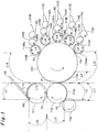
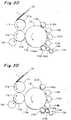
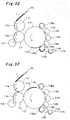
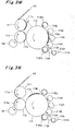
- Amain embodiment of the proof printing press according to the present invention will be described below based on Figs. 1 , 2 , and 3A to 3N .
- an impression cylinder 111 is rotatably disposed at a forward edge side of a sheet feed table 101 of a sheet feed device that is sheet feeding means for feeding sheets one by one.
- the impression cylinder 111 includes only one holding surface (working surface) 111a on an outer circumference thereof, the holding surface (working surface) 111a having a length L1 in a circumferential direction and configured to hold the sheet.
- the impression cylinder 111 has a grip device (not shown) configured to hold the sheet on the holding surface (working surface) 111a by gripping a forward edge side (gripping side) of the sheet, and is set to have such a diameter that the impression cylinder 111 has a size large enough to hold two sheets aligned in the circumferential direction, in other words, a size of a so-called "double-size cylinder.”
- a plate cylinder 112 is rotatably disposed to face the impression cylinder 111.
- the plate cylinder 112 is set to have such a diameter that the plate cylinder 112 has a size large enough to mount thereon two intaglio printing plates described above aligned in the circumferential direction, in other words, a size of a so-called "double-size cylinder.”
- a collecting cylinder 113 is rotatably disposed to face the plate cylinder 112.
- the collecting cylinder 113 is set to have such a diameter that the collecting cylinder 113 has a size large enough to mount thereon four blankets described above in the circumferential direction, in other words, a size of a so-called "quadruple-size cylinder.”
- chablon cylinders 114A to 114E are rotatably disposed to face the collecting cylinder 113, at predetermined intervals along the circumferential direction of the collecting cylinder 113.
- the chablon cylinders 114A to 114E are set to have such diameters that the chablon cylinders 114A to 114E each have a size large enough to install corresponding one of the mounting surfaces (working surfaces) 114Aa to 114Ea in the circumferential direction, in other words, a size of a so-called “single cylinder (single-size cylinder)."
- Form rollers 115A to 115E are rotatably disposed to face the chablon cylinders 114A to 114E, respectively.
- Fountain rollers 116A to 116E are rotatably disposed to face the form rollers 115A to 115E, respectively.
- the fountain rollers 116A to 116E are respectively provided with ink fountains 117A to 117E configured to store inks.
- a wiping roller 118 is rotatably disposed to face an outer circumferential surface of the plate cylinder 112, the outer circumferential surface located between a downstream side of a facing position P1 where the plate cylinder 112 faces the collecting cylinder 113 in a rotation direction of the plate cylinder 112 and an upstream side of a facing position P3 where the plate cylinder 112 faces the impression cylinder 111 in the rotation direction of the plate cylinder 112.
- the wiping roller 118 is configured to remove ink on the surfaces of the intaglio printing plates of the plate cylinder 112.
- the impression cylinder 111, the plate cylinder 112, the collecting cylinder 113, and the chablon cylinders 114A to 114E are connected to one another via a gear train in such a manner as to be rotatable in synchronism with one another.
- the plate cylinder 112 is provided with a rotary encoder 131(see Fig. 2 ) that is phase detecting means for detecting a rotation phase of the plate cylinder 112, in other words, detecting rotation phases of the cylinders 111 to 113 and 114A to 114E, to put it differently, detecting a phase of the printing press.
- the fountain rollers 116A to 116E are supported in such a manner as to be movable toward and away (thrown on/off) from the form rollers 115A to 115E.
- the ink fountains 117A to 117E are supported in such a manner as to be integrally movable in accordance with the above-described movements of the fountain rollers 116A to 116E.
- the form rollers 115A to 115E are supported in such a manner as to be movable toward and away (thrown on/off) from the chablon cylinders 114A to 114E (for example, the mechanism described in Patent Literature 2) .
- the impression cylinder 111 is supported by an eccentric bearing or the like in such a manner as to be movable toward and away (thrown on/off) from the plate cylinder 112.
- the sheet feed device including the sheet feed table 101 and the like is supported movably in such a manner as to follow a movement of the impression cylinder 111.
- the rotation phases of the chablon cylinders 114A to 114E and the collecting cylinder 113 are set such that when the mounting surfaces (working surfaces) 114Aa to 114Ea and 113a face each other in accordance with the rotations, the chablon cylinders 114A to 114E and the collecting cylinder 113 rotate in synchronism and in contact with each other, in other words, an end portion at a downstream side in a rotation direction of the mounting surface (working surface) 113a of the collecting cylinder 113 and an end portion at a downstream side in a rotation direction of each of the mounting surfaces (working surfaces) 114Aa to 114Ea of the chablon cylinders 114A to 114E rotate in synchronism and in contact with each other (see Fig. 3E ).
- the chablon cylinders 114A to 114E and the collecting cylinder 113 are not in contact with each other unless the mounting surfaces (working surfaces) 114Aa to 114Ea
- the rotation phases of the collecting cylinder 113 and the plate cylinder 112 are set such that when the mounting surfaces (working surfaces) 113a and 112a face each other in accordance with the rotations, the collecting cylinder 113 and the plate cylinder 112 rotate in synchronism and in contact with each other, in other words, the end portion at the downstream side in the rotation direction of the mounting surface (working surface) 113a of the collecting cylinder 113 and an end portion at a downstream side in a rotation direction of the mounting surface (working surface) 112a of the plate cylinder 112 rotate in synchronism and in contact with each other (see Figs. 3G to 3I ). Hence, the collecting cylinder 113 and the plate cylinder 112 are not in contact with each other unless the mounting surfaces (working surfaces) 113a and 112a face each other.
- the rotation phase of the impression cylinder 111 is set such that when the impression cylinder 111 approaches the plate cylinder 112 and rotates, the holding surface (working surface) 111a is rotatable in synchronism and in contact with the mounting surface (working surface) 112a of the plate cylinder 112 (see Fig. 3L ).
- the impression cylinder 111, the collecting cylinder 113, and the wiping roller 118 are positioned relative to the plate cylinder 112 such that a length L11 of the outer circumference of the plate cylinder 112 at the downstream side of the facing position P1 in the rotation direction of the plate cylinder 112 is longer than the length L2 of the mounting surface (working surface) 112a of the plate cylinder 112 (L11>L2), where the length L11 extends between the facing position P1 where the plate cylinder 112 faces the collecting cylinder 113 and a facing position P2 where the plate cylinder 112 faces the wiping roller 118, and that a length L12 of the outer circumference of the plate cylinder 112 at a downstream side of the facing position P2 in the rotation direction of the plate cylinder 112 is longer than the length L2 of the mounting surface (working surface) 112a of the plate cylinder 112 (L12>L2), where the length L12 extends between the facing position P2 and the facing position P3 where the plate cylinder 112
- the chablon cylinders 114A located at the most upstream side of the facing position P1 in the rotation direction of the collecting cylinder 113 and the chablon cylinder 114E located at the most downstream side of the facing position P1 in the rotation direction of the collecting cylinder 113 as well as the other chablon cylinders 114B to 114D located between the chablon cylinders 114A and 114E are positioned relative to the collecting cylinder 113 such that a length L13 of the outer circumference of the collecting cylinder 113 at the downstream side of the facing position P1 in the rotation direction of the collecting cylinder 113 is longer than the length L3 of the mounting surface (working surface) 113a of the collecting cylinder 113 (L13>L3), where the length L13 extends between the facing position P1 and a facing position P4 where the collecting cylinder 113 faces the chablon cylinder 114A located at the most upstream side, and that a length L14 of the outer circumference of the collecting cylinder 113
- the sheet feed table 101 is positioned relative to the impression cylinder 111 such that a length L15 of the outer circumference of the impression cylinder 111 at a downstream side of a supplying position P6 in a rotation direction of the impression cylinder 111 is longer than the length L1 of the holding surface (working surface) 111a of the impression cylinder 111 (L15>L1), where the length L15 extends between the facing position P3 and the supplying position P6, the supplying position P6 is a position where the sheet 1 is supplied from the sheet feed table 101 to the holding surface (working surface) 111a of the impression cylinder 111, and that a length L16 of the outer circumference of the impression cylinder 111 at an upstream side of the supplying position P6 in the rotation direction of the impression cylinder 111 is longer than the length L1 of the holding surface (working surface) 111a of the impression cylinder 111 (L16>L1), where the length L16 extends between the facing position P3 and the supplying position P6.
- the rotary encoder 131 is electrically connected to an input portion of the controller 130 that is controlling means.
- An output portion of the controller 130 is electrically connected to: a drive motor 121 configured to rotate the cylinders 111 to 113 and 114A to 114E; drive motors 122A to 122E that are form-roller-rotation driving means and configured to rotate the form rollers 115A to 115E; drive motors 123A to 123E that are fountain-roller-rotation driving means and configured to rotate the fountain rollers 116A to 116E; a drive motor 124 configured to rotate the wiping roller 118; an impression-cylinder throw-on/off device 125 that is impression-cylinder-throw-on/off driving means such as a pneumatic cylinder configured to rotate the eccentric bearing or the like in such a manner that the impression cylinder 111 is moved toward and away (thrown on/off) from the plate cylinder 112; ink-supplying throw-on/off devices 126A to 126E that
- the input portion of the controller 130 is electrically connected to a printing operation start switch 130a configured to output a signal to start a printing operation.
- the controller 130 is capable of controlling operations of the motors 121, 122A to 122E, 123A to 123E, 124, the throw-on/off device 125, 126A to 126E, 127A to 127E, and the feeder 128 on the basis of signals from the switch 130a and the rotary encoder 131 (the details will be described later).
- the fountain rollers 116A to 116E, the ink fountains 117A to 117E, and the like constitute multiple (five) ink supplying means; the wiping roller 118, the drive motor 124, and the like constitute wiping means; and the drive motor 121, the gear train, and the like constitute cylinder-rotation driving means.
- the impression cylinder 111 is located at a position away (thrown off) from the plate cylinder 112
- the form rollers 115A to 115E are located at positions away (thrown off) from the chablon cylinders 114A to 114E
- the fountain rollers 116A to 116E are located at positions away (thrown off) from the form rollers 115A to 115E (see Fig. 3A ).
- the controller 130 controls the operation of the drive motor 121 in such a manner that the cylinders 111 to 113 and 114A to 114E are rotated in synchronism with one another, and controls the operation of the drive motor 124 in such a manner that the wiping roller 118 is rotated, on the basis of the signal from the printing operation start switch 130a.
- the controller 130 controls the operations of the ink-supplying throw-on/off devices 12 6A to 126E in such a manner that the fountain rollers 116A to 116E are brought into contact with (thrown on) the form rollers 115A to 115E, and controls the operations of the drive motors 122A to 122E and 123A to 123E in such a manner that the fountain rollers 116A to 116E and the form rollers 115A to 115E are rotated (see Fig. 3B ).
- inks are supplied to outer circumferential surfaces of the form rollers 115A to 115E between upstream sides of positions facing the chablon cylinders 114A to 114E in the rotation directions of the form rollers 115A to 115E and downstream sides of positions facing the fountain rollers 116A to 116E in the rotation directions (see Fig. 3C ).
- inks in the ink fountains 117A to 117E are extracted in accordance with the rotations of the fountain rollers 116A to 116E.
- the inks are supplied to the outer circumferential surfaces of the form rollers 115A to 115E.
- the controller 130 controls the operations of the form-roller-throw-on/off devices 127A to 127E on the basis of information from the rotary encoder 131 in such a manner that the form rollers 115A to 115E are brought into contact with (thrown on) segment plates mounted on the mounting surfaces (working surfaces) 114Aa to 114Ea of the chablon cylinders 114A to 114E (see Fig. 3C ).
- inks are supplied from the fountain rollers 116A to 116E via the form rollers 115A to 115E to the segment plates on the chablon cylinders 114A to 114E.
- the controller 130 controls the operations of the ink-supplying throw-on/off devices 126A to 126E in such a manner that the fountain rollers 116A to 116E are moved away (thrown off) from the form rollers 115A to 115E, and simultaneously controls the operations of the drive motors 123A to 123E in such a manner that the rotations of the fountain rollers 116A to 116E are stopped, on the basis of information from the rotary encoder 130 (see Fig.
- each outer circumferential surface of the form rollers 115A to 115E is supplied with ink in an amount corresponding to the length L4 of the mounting surfaces (working surfaces) 114Aa to 114Ea of the chablon cylinders 114A to 114E.
- the controller 130 controls the operations of the form-roller-throw-on/off devices 127A to 127E in such a manner that the form rollers 115A to 115E are moved away (thrown off) from the chablon cylinders 114A to 114E, and simultaneously controls the operations of the drive motors 122A to 122E in such a manner that the rotations of the form rollers 115A to 115E are stopped, on the basis of information from the rotary encoder 131 (see Fig. 3E ).
- the inks having been supplied to the outer circumferential surfaces of the form rollers 115A to 115E are completely supplied over the entire lengths of the segment plates on the mounting surfaces (working surfaces) 114Aa to 114Ea of the chablon cylinders 114A to 114E.
- the inks are supplied to the segment plates on the mounting surfaces (working surfaces) 114Aa to 114Ea of the chablon cylinders 114A to 114E, the inks are sequentially transferred to the blankets mounted on the mounting surface (working surface) 113a of the collecting cylinder 113 in accordance with the rotation of the collecting cylinder 113 (see Fig. 3F ).
- the blankets on the collecting cylinder 113 are brought into contact with the intaglio printing plates mounted on the mounting surface (working surface) 112a of the plate cylinder 112 to transfer the inks (see Fig. 3G ).
- the wiping roller is not in contact with the intaglio printing plates on the plate cylinder 112. Accordingly, it is possible to prevent a disturbance to the intaglio printing plates, so that the inks can be transferred evenly from the blankets to the intaglio printing plates.
- the blankets on the collecting cylinder 113 transfer the inks to the intaglio printing plates on the plate cylinder 112. Accordingly, when the inks are transferred from the blankets on the collecting cylinder 113 to the intaglio printing plates on the plate cylinder 112, it is possible to prevent a disturbance to the blankets, and the inks can be transferred evenly from the blankets to the intaglio printing plates more reliably
- the controller 130 controls the operations of the ink-supplying throw-on/off devices 126A to 126E in such a manner that the fountain rollers 116A to 116E are brought into contact with (thrown on) the form rollers 115A to 115E again, and controls the operations of the drive motors 122A to 122E and 123A to 123E in such a manner that the fountain rollers 116A to 116E and the form rollers 115A to 115E are rotated again (see Fig. 3H ) .
- the controller 130 controls the operations of the form-roller-throw-on/off devices 127A to 127E on the basis of information from the rotary encoder 131 in such a manner that the form rollers 115A to 115E are again brought into contact with (thrown on) the segment plates on the mounting surfaces (working surfaces) 114Aa to 114Ea of the chablon cylinders 114A to 114E (see Fig. 3I ).
- the controller 130 controls the operation of the impression-cylinder throw-on/off device 125 in such a manner that the impression cylinder 111 is moved toward (thrown on) the plate cylinder 112, and controls the operation of the feeder 128 in such a manner that the sheet 1 on the sheet feed table 101 is fed to the impression cylinder 111, on the basis of information from the rotary encoder 131.
- a forward edge side (gripping side) of the sheet 1 on the sheet feed table 101 is gripped by the grip device of the impression cylinder 111 and thereby held on the holding surface (working surface) 111a.
- the wiping roller 118 removes extra inks on the surfaces of the intaglio printing plates on the plate cylinder 112 (see Fig. 3J ).
- inks are supplied from the fountain rollers 116A to 116E via the form rollers 115A to 115E to the segment plates on the chablon cylinders 114A to 114E.
- the controller 130 controls the operations of the ink-supplying throw-on/off devices 126A to 126E in such a manner that the fountain rollers 116A to 116E are moved away (thrown off) from the form rollers 115A to 115E again, and simultaneously controls the operations of the drive motors 123A to 123E in such a manner that the rotations of the fountain rollers 116A to 116E are stopped again, on the basis of information from the rotary encoder 130 (see Fig. 3J ).
- each outer circumferential surface of the form rollers 115A to 115E is again supplied with ink in an amount corresponding to the length L4 of the mounting surfaces (working surfaces) 114Aa to 114Ea of the chablon cylinders 114A to 114E.
- the controller 130 controls the operations of the form-roller-throw-on/off devices 127A to 127E in such a manner that the chablon cylinders 114A to 114E are moved away (thrown off) from the form rollers 115A to 115E again, and simultaneously controls the operations of the drive motors 122A to 122E in such a manner that the rotations of the form rollers 115A to 115E are stopped again, on the basis of information from the
- the inks having been supplied again to the outer circumferential surfaces of the form rollers 115A to 115E are completely supplied again over the entire lengths of the segment plates on the mounting surfaces (working surfaces) 114Aa to 114Ea of the chablon cylinders 114A to 114E.
- the inks are supplied again to the segment plates on the mounting surfaces (working surfaces) 114Aa to 114Ea of the chablon cylinders 114A to 114E, the inks are again sequentially transferred to the blankets on the mounting surface (working surface) 113a of the collecting cylinder 113 in accordance with the rotation of the collecting cylinder 113 (see Figs. 3L to 3N ).
- the sheet 1 is transported while being held over the entire surface of the holding surface ⁇ working surface) 111a of the impression cylinder 111, and the wiping roller 118 removes all the extra inks on the surfaces of the intaglio printing plates on the plate cylinder 112 ⁇ see Fig. 3K ).
- the sheet 1 on the holding surface (working surface) 111a of the impression cylinder 111 is brought into contact with the intaglio printing plates on the plate cylinder 112, so that the ink corresponding to a pattern on the intaglio printing plates is transferred to the sheet 1 (see Fig. 3L ).
- the wiping roller 118 removes all the extra inks on the surfaces of the intaglio printing plates on the plate cylinder 112
- the intaglio printing plates on the plate cylinder 112 come into contact with the sheet 1 transported while being held on the holding surface (working surface) 111a of the impression cylinder 111 to transfer the inks. Accordingly, it is possible to prevent a disturbance to the intaglio printing plates when the inks are transferred from the intaglio printing plates to the sheet 1, and the inks can be transferred evenly from the intaglio printing plates to the sheet 1.
- the intaglio printing plates on the plate cylinder 112 come into contact with the sheet 1 on the impression cylinder 111 to transfer the inks. Accordingly, it is possible to prevent a disturbance to the sheet 1 when the inks are transferred from the intaglio printing plates to the sheet 1, and the inks can be transferred evenly from the intaglio printing plates to the sheet 1 more reliably.
- the controller 130 controls the operation of the impression-cylinder throw-on/off device 125 on the basis of a signal from the rotary encoder 131 in such a manner that the impression cylinder 111 is moved away (thrown off) from the plate cylinder 112 (see Fig. 3M ).
- the forward edge side (gripping side) of the sheet 1 held on the holding surface 111a of the impression cylinder 111 is released from the grip device, and the sheet 1 is collected from the holding surface 111a of the impression cylinder 111 (see Fig. 3N ).
- the proof printing press 100 is capable of significantly reducing printing failure.
- a fountain roller having a length L6' in a circumferential direction of an outer circumferential surface thereof, the length L6' being longer than the length in the circumferential direction of the outer circumferential surfaces of the form rollers 115A to 115E, or a fountain roller having a length L6" in a circumferential direction of an outer circumferential surface thereof, the length L6" being shorter than the length in the circumferential direction of the outer circumferential surfaces of the form rollers 115A to 115E.
- the drive motors 122A to 122E configured to rotate the form rollers 115A to 115E and the drive motors 123A to 123E configured to rotate the fountain rollers 116A to 116E are independently provided.
- the form rollers and the fountain rollers may be connected to the same drive motor via an electromagnetic clutch or the like, and a control may be performed on the operation to turn on and off the electromagnetic clutch or the like.
- the drive motors 122A to 122E configured to rotate the form rollers 115A to 115E may be omitted, but the form rollers 115A to 115E are brought into contact with (thrown on) the fountain rollers 116A to 116E and the chablon cylinders 114A to 114E, so that the form rollers 115A to 115E can rotate automatically only in an manner accompanying the rotations of the fountain rollers 116A to 116E and the chablon cylinders 114A to 114E.
- the form-roller-rotation driving means may be constituted of the drive motor 121, the drive motors 123A to 123E, the ink-supplying throw-on/off devices 126A to 126E, the form-roller-throw-on/off devices 127A to 127E, and the like.
- form-roller-rotation braking means having a brake shoe or the like configured to stop the rotations of the form rollers 115A to 115E is provided.
- the operation of the form-roller-rotation braking means may be controlled by the controlling means so that the form rollers 115A to 115E can rotate in a manner accompanying the rotations of the fountain rollers 116A to 116E or the chablon cylinders 114A to 114E.
- the operation of the form-roller-rotation braking means may be controlled by the controlling means so that the rotations of the form rollers 115A to 115E are stopped quickly.
- the fountain rollers 116A to 116E and the ink fountains 117A to 117E are movable toward and away (thrown on/off) from the form rollers 115A to 115E by the ink-supplying throw-on/off devices 126A to 126E, while the form rollers 115A to 115E are movable toward and away (thrown on/off) from the chablon cylinders 114A to 114E by the form-roller-throw-on/off devices 127A to 127E.
- the form roller can be configured to be movable toward and away (thrown on/off) from each of the fountain roller and the chablon cylinder by the form-roller-throw-on/off driving means.
- a photosensor or the like may be disposed to face the outer circumferential surface of the collecting cylinder 113 or the plate cylinder 112 so as to constitute position detecting means for detecting a rotation direction position of the mounting surface (working surface) 113a of the collecting cylinder 113 or a rotation direction position of the mounting surface (working surface) 112a of the plate cylinder 112, so that ink supply from the ink supplying means can be controlled.
- the sheet feed device including the sheet feed table 101, the feeder 128, and the like is substituted with a sheet feed device configured to sequentially send multiple sheets stacked on a paper feed tray onto a feeder board and feed the sheets one by one to an impression cylinder using a swing arm shaft pregripper.
- the photosensor or the like may be disposed on and face the feeder board so as to constitute position detecting means for detecting a position of a sheet fed to the impression cylinder, so that ink supply from ink supplying means can be controlled.
- the impression cylinder 111, the plate cylinder 112, the collecting cylinder 113, and the chablon cylinders 114A to 114E are connected to one another via the gear train in such a manner as to be rotatable in synchronism with one another by the operation of the drive motor 121.
- drive motors may be connected respectively to the cylinders 111 to 113 and 114A to 114E, and the operations of these drive motors may be controlled in synchronism with one another by the controlling means in such a manner that the cylinders 111 to 113 and 114A to 114E can rotate in synchronism with one another.
- the impression cylinder, the plate cylinder, and the collecting cylinder may be cylinders of the same size.
- the proof printing press according to the present invention is capable of reducing uneven transfer onto a sheet and thereby reducing printing failure, and therefore is quite beneficially usable in the printing industry.
Landscapes
- Engineering & Computer Science (AREA)
- Mechanical Engineering (AREA)
- Rotary Presses (AREA)
- Inking, Control Or Cleaning Of Printing Machines (AREA)
Claims (6)
- Prüfdruckmaschine (100) miteinem drehbar gelagerten Plattenzylinder (112), der an seinem äußeren Umfang eine Arbeitsfläche (112a) aufweist, auf der eine Tiefdruckplatte angebracht ist;einem drehbar gelagerten Druckzylinder (111), der dem Plattenzylinder (112) gegenüberliegt und an seinem äußeren Umfang eine Arbeitsfläche (111a) aufweist, die zum Halten eines Blatts (1) eingerichtet ist;einem drehbar gelagerten Sammelzylinder (113), der dem Plattenzylinder (112) gegenüberliegt und an seinem äußeren Umfang eine Arbeitsfläche (113a) aufweist, auf der ein Drucktuch angebracht ist;einer Anzahl von Chablon-Zylindern (114A bis 114E), die entlang einer Umfangsrichtung des Sammelzylinders (113) angeordnet sind und drehbar gelagert sind, um dem Sammelzylinder (113) gegenüberzuliegen, und an ihrem äußeren Umfang Arbeitsflächen (114Aa bis 114Ea) aufweisen, auf denen Segmentplatten angebracht sind;einer Anzahl von drehbar gelagerten Formrollen (115A bis 115E), die jeweils den Chablon-Zylindern (114A bis 114E) gegenüberliegen;einer Anzahl von Druckfarben-Zufuhreinrichtungen (116A bis 116E, 117A bis 117E) zum Zuführen von Druckfarben zu den jeweiligen Formrollen (115A bis 115E); undWischeinrichtungen (118, 124), die gegenüber dem Plattenzylinder (112) zwischen einer stromabwärts gelegenen Seite einer gegenüberliegenden Position (P1), wo der Plattenzylinder (112) dem Sammelzylinder (113) gegenüberliegt, in Drehrichtung des Plattenzylinders (112), und einer stromaufwärts gelegenen Seite einer gegenüberliegenden Position (P3), wo der Plattenzylinder (112) dem Druckzylinder (111) gegenüberliegt, in Drehrichtung des Plattenzylinders (112), angeordnet sind, wobei die Wischeinrichtungen (118, 124) zum Entfernen von Druckfarbe an einer Oberfläche der Tiefdruckplatte des Plattenzylinders (112) sind,wobei der Plattenzylinder (112) eine Größe eines vielfachen Zylinders hat und groß genug ist, um darauf eine Anzahl von Tiefdruckplatten in Umfangsrichtung ausgerichtet anzubringen, während die Anzahl der Arbeitsflächen (112a) des Plattenzylinders (112) lediglich eins beträgt,wobei die Chablon-Zylinder (114A bis 114E) Zylinder on Einzelgröße sind,wobei die Chablon-Zylinder (114A bis 114E) sich eine Anzahl von Malen drehen, während der Plattenzylinder (112) sich einmal dreht,wobei der Druckzylinder (111), der Sammelzylinder (113) und die Wischeinrichtungen (118, 124) relativ zu dem Plattenzylinder (112) derart angeordnet sind, dasseine Länge (L11) des äußeren Umfangs des Plattenzylinders (112) an einer stromabwärts gelegenen Seite der gegenüberliegenden Position (P1), wo der Plattenzylinder (112) dem Sammelzylinder (113) gegenüberliegt, in einer Drehrichtung des Plattenzylinders (112), länger ist als eine Länge (L2) der Arbeitsfläche (112a) des Plattenzylinders (112) in einer Umfangsrichtung des Plattenzylinders (112), wobei sich die Länge (L11) des äußeren Umfangs des Plattenzylinders (112) zwischen der gegenüberliegenden Position (P1), wo der Plattenzylinder (112) dem Sammelzylinder (113) gegenüberliegt, und einer gegenüberliegenden Position (P2), wo der Plattenzylinder (112) den Wischeinrichtungen (118, 124) gegenüberliegt, erstreckt, und eine Länge (L12) des äußeren Umfangs des Plattenzylinders (112) an einer stromabwärts gelegenen Seite der gegenüberliegenden Position (P2), wo der Plattenzylinder (112) den Wischeinrichtungen (118, 124) gegenüberliegt, in der Drehrichtung des Plattenzylinders (112), länger ist als die Länge (L2) in der Umfangsrichtung der Arbeitsfläche (112a) des Plattenzylinders (112), wobei sich die Länge (L12) des äußeren Umfangs des Plattenzylinders (112) zwischen der gegenüberliegenden Position (P2), wo der Plattenzylinder (112) den Wischeinrichtungen (118, 124) gegenüberliegt, und der gegenüberliegenden Position (P3), wo der Plattenzylinder (112) dem Druckzylinder (111) gegenüberliegt, erstreckt,wobei Drehphasen des Sammelzylinders (113) und der Chablon-Zylinder (114A bis 114E) so eingestellt sind, dass sich ein Endbereich an einer stromabwärts gelegenen Seite in einer Drehrichtung der Arbeitsfläche (113a) des Sammelzylinders (113) und ein Endbereich an einer stromabwärts gelegenen Seite in einer Drehrichtung jeder der Arbeitsflächen (114Aa bis 114Ea) der Chablon-Zylinder (114A bis 114E) synchron und in Kontakt miteinander gemäß den Drehbewegungen des Sammelzylinders (113) und der Chablon-Zylinder (114A bis 114E) drehen,wobei eine Länge der äußeren Umfangsflächen der Formrollen (115A bis 115E) in einer Umfangsrichtung der Formrollen (115A bis 115E) gleich ist zu einer Länge (L4) in einer Umfangsrichtung der Arbeitsflächen (114Aa bis 114Ea) der Chablon-Zylinder (114A bis 114E), undwobei die Wischeinrichtungen (118, 124) nicht in Kontakt mit den Tiefdruckplatten auf dem Plattenzylinder (112) sind, während Druckfarben von dem Drucktuch auf dem Sammelzylinder (113) zu den Tiefdruckplatten auf dem Plattenzylinder (112) übertragen werden.
- Prüfdruckmaschine (100) nach Anspruch 1, dadurch gekennzeichnet, dass fünf der Chablon-Zylinder (114A bis 114E) entlang der Umfangsrichtung des Sammelzylinders (113) angeordnet sind und die Chablon-Zylinder (114A bis 114E) derart angeordnet sind, dasseine Länge (L13) des äußeren Umfangs des Sammelzylinders (113) an der stromabwärts gelegenen Seite der gegenüberliegenden Position (P1), wo der Plattenzylinder (112) dem Sammelzylinder (113) gegenüberliegt, in der Drehrichtung des Sammelzylinders (113), länger ist als eine Länge (L3) der Arbeitsfläche (113a) des Sammelzylinders (113) in der Umfangsrichtung des Sammelzylinders (113), wobei sich die Länge (L13) des äußeren Umfangs des Sammelzylinders (113) zwischen der gegenüberliegenden Position (P1), wo der Plattenzylinder (112) dem Sammelzylinder (113) gegenüberliegt, und einer gegenüberliegenden Position (P4) erstreckt, wo der Sammelzylinder (113) dem Chablon-Zylinder (114A) gegenüberliegt, der an der am meisten stromaufwärts gelegenen Seite der gegenüberliegenden Position (P1) gelegen ist, wo der Plattenzylinder (112) dem Sammelzylinder (113) gegenüberliegt, in der Drehrichtung des Sammelzylinders (113a), undeine Länge (L14) des äußeren Umfangs des Sammelzylinders (113) an einer stromaufwärts gelegenen Seite der gegenüberliegenden Position (P1), wo der Plattenzylinder (112) dem Sammelzylinder (113) gegenüberliegt, in der Drehrichtung des Sammelzylinders (113), länger ist als die Länge (L3) in der Umfangsrichtung der Arbeitsfläche (113a) des Sammelzylinders (113), wobei sich die Länge (L14) des äußeren Umfangs des Sammelzylinders (113) zwischen der gegenüberliegenden Position (P1), wo der Plattenzylinder (112) dem Sammelzylinder (113) gegenüberliegt, und einer gegenüberliegenden Position (P5), wo der Sammelzylinder (113) dem Chablon-Zylinder (114E) gegenüberliegt, der sich an der am meisten stromabwärts gelegenen Seite der gegenüberliegenden Position (P1) befindet, wo der Plattenzylinder (112) dem Sammelzylinder (113) gegenüberliegt, in der Drehrichtung des Sammelzylinders (113).
- Prüfdruckmaschine (100) nach einem der Ansprüche 1 und 2, dadurch gekennzeichnet, dass die Prüfdruckmaschine (100) aufweist:wenigstens eine Erfassungseinrichtungeiner Positionserfassungseinrichtung zum Erfassen wenigstens einer Position einer Drehrichtungsposition der Arbeitsfläche (112a) des Plattenzylinders (112), einer Drehrichtungsposition der Arbeitsfläche (113a) des Sammelzylinders (113) und einer Position des dem Druckzylinder (111) zugeführten Blatts (1), undeiner Phasenerfassungseinrichtung (131) zum Erfassen einer Phase der Druckmaschine (100); undeine Steuereinrichtung (130) zum Steuern der Druckfarbenzufuhr von den Druckfarben-Zufuhreinrichtungen (116A bis 116E, 117A bis 117E) auf Basis von Information von den Erfassungseinrichtungen auf eine solche Weise, dass dann, wenn die Endbereiche an den stromabwärts gelegenen Seiten in den Drehrichtungen der Arbeitsflächen (114Aa bis 114Ea) der Chablon-Zylinder (114A bis 114E) den Formrollen (115A bis 115E) gegenüberliegen, die Druckfarben den äußeren Umfangsflächen der Formrollen (115A bis 115E) zwischen stromaufwärts gelegenen Seiten von Positionen, die den Chablon-Zylindern (114A bis 114E) in Drehrichtung der Formrollen (115A bis 115E) gegenüberliegen, und stromabwärts gelegenen Seiten von Druckfarben-Zufuhrpositionen von den Druckfarben-Zufuhreinrichtungen (116A bis 116E, 117A bis 117E) in den Drehrichtungen der Formrollen (115A bis 115E) zugeführt werden.
- Prüfdruckmaschine (100) nach Anspruch 3, dadurch gekennzeichnet, dassdie Formrollen (115A bis 115E) auf solche Weise gelagert sind, dass sie auf die Chablon-Zylinder (114A bis 114E) zu und davon weg bewegbar sind,die Druckfarben-Zufuhreinrichtungen (116A bis 116E, 117 A bis 117E) Tauchwalzen (116A bis 116E) aufweisen, die auf eine solche Weise drehbar gelagert sind, dass sie auf die Formrollen (115A bis 115E) zu und davon weg bewegbar sind, und die dazu eingerichtet sind, Druckfarben in Druckfarben-Farbwerken (117A bis 117E) den Formrollen (115A bis 115E) zuzuführen,wobei die Prüfdruckmaschine (100) aufweist:Formrollen-Drehantriebseinrichtungen (122A bis 122E) zum Drehen der Formrollen (115A bis 115E);Formrollen-Anwerf/Abwerf-Antriebseinrichtungen (127A bis 127E) zum Bewegen der Formrollen (115A bis 115E) auf die Chablon-Zylinder (114A bis 114E) zu und davon weg;Tauchwalzen-Drehantriebseinrichtungen (123A bis 123E) zum Drehen der Tauchwalzen (116A bis 116E); undTauchwalzen-Anwerf/Abwerf-Antriebseinrichtungen (126A bis 126E) zum Bewegen der Tauchwalzen (116A bis 116E); auf die Formrollen (115A bis 115E) zu und davon weg,wobei die Erfassungseinrichtungen wenigstens die Phasenerfassungseinrichtung (131) aufweisen, undwobei die Steuereinrichtung (130)die Tauchwalzen-Anwerf/Abwerf-Antriebseinrichtungen (126A bis 126E) auf eine solche Weise steuert, dass die Tauchwalzen (116A bis 116E) in Kontakt mit den Formrollen (115A bis 115E) gebracht werden, und die Formrollen-Drehantriebsteinrichtungen (122A bis 122E) und die Tauchwalzen-Drehantriebseinrichtungen (123A bis 123E) auf eine solche Weise steuert, dass die Tauchwalzen (116A bis 116E) und die Formrollen (115A bis 115E) gedreht werden, auf Basis von Information von der Phasenerfassungseinrichtung (131), so dass dann, wenn die Endbereiche an den stromabwärts gelegenen Seiten in den Drehrichtungen der Arbeitsflächen (114Aa bis 114Ea) der Chablon-Zylinder (114A bis 114E) den Formzylindern (115A bis 115E) gegenüberliegen, Druckfarben den äußeren Umfangsflächen der Formrollen (115A bis 115E) zwischen den stromaufwärts gelegenen Seiten der den Chablon-Zylindern (114A bis 114E) gegenüberliegenden Positionen in den Drehrichtungen der Formrollen (115A bis 115E) und den stromabwärts gelegenen Seiten der den Tauchwalzen (116A bis 116E) gegenüberliegenden Positionen in den Drehrichtungen der Formrollen (115A bis 115E) zugeführt werden,die Formrollen-Anwerf/Abwerf-Antriebseinrichtungen (127A bis 127E) auf eine solche Weise steuert, dass die Formrollen (115A bis 115E) in Kontakt mit den Segmentplatten an den Arbeitsflächen (114Aa bis 114Ea) der Chablon-Zylinder (114A bis 114E) gebracht werden, auf Basis von Information von der Phasenerfassungseinrichtung (131), wenn die Endbereiche der stromabwärts gelegenen Seiten in den Drehrichtungen der Arbeitsflächen (114Aa bis 114Ea) der Chablon-Zylinder (114A bis 114E) den Formrollen (115A bis 115E) gegenüberliegen,die Tauchwalzen-Anwerf/Abwerf-Antriebseinrichtungen (126A bis 126E) auf eine solche Weise steuert, dass die Tauchwalzen (116A bi 116E) von den Formrollen (115A bis 115E) wegbewegt werden, auf Basis von Information von der Phasenerfassungseinrichtung (131), bei Vervollständigung einer Drehbewegung der Formrollen (115A bis 115E), nach Beginn der Zufuhr von Druckfarben zu den Formrollen (115A bis 115E), unddie Formrollen-Anwerf/Abwerf-Antriebseinrichtungen (127A bis 127E) auf eine solche Weise steuert, dass die Formrollen (115A bis 115E) von den Chablon-Zylindern (114A bis 114E) wegbewegt werden, und gleichzeitig die Formrollen-Drehantriebseinrichtungen (122A bis 122E) auf eine solche Weise steuert, dass die Drehbewegungen der Formrollen (115A bis 115E) gestoppt werden, auf Basis von Information von der Phasenerfassungseinrichtung (131), bei Beendigung einer Drehbewegung, nachdem die Formrollen (115A bis 115E) in Kontakt mit den Segmentplatten an den Arbeitsflächen (114Aa bis 114Ea) der Chablon-Zylinder (114A bis 114E) gebracht sind.
- Prüfdruckmaschine (100) nach Anspruch 4, dadurch gekennzeichnet, dassdie Prüfdruckmaschine (100) Blattzufuhreinrichtungen (101, 128) zum Zuführen des Blatts (1) an den Druckzylinder (111) aufweist unddie Steuereinrichtung (130) die Blattzufuhreinrichtungen (101, 128) auf eine solche Weise steuert, dass das Blatt (1) dem Druckzylinder (111) zugeführt wird, auf Basis von Information von der Phasenerfassungseinrichtung (131), nachdem die Druckfarben von den Chablon-Zylindern (114A bis 114E) auf das Drucktuch an dem Sammelzylinder (113) übertragen sind und die Druckfarben von dem Drucktuch an dem Sammelzylinder (113) auf die Tiefdruckplatten an der Arbeitsfläche (112a) des Plattenzylinders (112) übertragen sind.
- Prüfdruckmaschine (100) nach Anspruch 5, dadurch gekennzeichnet, dass die Steuereinrichtung (130)die Tauchwalzen-Anwerf/Abwerf-Antriebseinrichtungen (126A bis 126E) auf eine solche Weise steuert, dass die Tauchwalzen (116A bis 116E) erneut in Kontakt mit den Formrollen (115A bis 115E) gebracht werden, und die Formrollen-Drehantriebseinrichtungen (122A bis 122E) und die Tauchwalzen-Drehantriebseinrichtungen (123A bis 123E) auf eine solche Weise steuert, dass die Tauchwalzen (116A bis 116E) und die Formrollen (115A bis 115E) erneut gedreht werden, auf Basis von Information von der Phasenerfassungseinrichtung (131), so dass, wenn die von den Chablon-Zylindern (114A bis 114E) auf das Drucktuch an dem Sammelzylinder (113) übertragenen Druckfarben vollständig von dem Drucktuch an dem Sammelzylinder (113) zu den Tiefdruckplatten auf der Arbeitsfläche (112a) des Plattenzylinders (112) übertragen sind und dann die Endbereiche an den stromabwärts gelegenen Seiten, in den Drehrichtungen der Arbeitsflächen (114Aa bis 114Ea) der Chablon-Zylinder (114A bis 114E), wiederum den Formrollen (115A bis 115E) gegenüberliegen, Druckfarben wiederum den äußeren Umfangsflächen der Formrollen (115A bis 115E) zwischen den stromaufwärts gelegenen Seiten der den Chablon-Zylindern (114A bis 114E) gegenüberliegenden Positionen in den Drehrichtungen der Formrollen (115A bis 115E) und den stromabwärts gelegenen Seiten der den Tauchwalzen (116A bis 116E) gegenüberliegenden Positionen in den Drehrichtungen der Formrollen (115A bis 115E) zugeführt werden,die Formrollen-Anwerf/Abwerf-Antriebseinrichtungen (127A bis 127E) auf eine solche Weise steuert, dass die Formrollen (115A bis 115E) wiederum in Kontakt mit den Segmentplatten an den Arbeitsflächen (114Aa bis 114Ea) der Chablon-Zylinder (114A bis 114E) gebracht werden, auf Basis von Information von der Phasenerfassungseinrichtung (131), wenn die Endbereiche an den stromabwärts gelegenen Seiten in den Drehrichtungen der Arbeitsflächen (114Aa bis 114Ea) der Chablon-Zylinder (114A bis 114E) den Formrollen (115A bis 115E) gegenüberliegen,die Tauchwalzen-Anwerf/Abwerf-Antriebseinrichtungen (126A bis 126E) auf eine solche Weise steuert, dass die Tauchwalzen (116A bis 116E) wieder von den Formrollen (115A bis 115E) wegbewegt werden, auf Basis von Information von der Phasenerfassungseinrichtung (131), bei Beendigung einer Drehbewegung der Formrollen (115A bis 115E) nach Beginn einer erneuten Zuführung von Druckfarben an die Formrollen (115A bis 115E), unddie Formrollen-Anwerf/Abwerf-Antriebseinrichtungen (127A bis 127E) auf eine solche Weise steuert, dass die Formrollen (115A bis 115E) wieder von den Chablon-Zylindern (114A bis 114E) wegbewegt werden, und gleichzeitig die Formrollen-Drehantriebseinrichtungen (122A bis 112E) auf eine solche Weise steuert, dass die Drehbewegungen der Formrollen (115A bis 115E) wieder gestoppt werden, auf Basis von Information von der Phasenerfassungseinrichtung (131), bei Beendigung einer Drehbewegung, nachdem die Formrollen (115A bis 115E) wiederum in Kontakt mit den Segmentplatten an den Arbeitsflächen (114Aa bis 114Ea) der Chablon-Zylinder (114A bis 114E) gebracht sind.
Applications Claiming Priority (1)
| Application Number | Priority Date | Filing Date | Title |
|---|---|---|---|
| JP2013163855A JP6137541B2 (ja) | 2013-08-07 | 2013-08-07 | 校正印刷機 |
Publications (3)
| Publication Number | Publication Date |
|---|---|
| EP2835257A2 EP2835257A2 (de) | 2015-02-11 |
| EP2835257A3 EP2835257A3 (de) | 2015-03-25 |
| EP2835257B1 true EP2835257B1 (de) | 2017-11-01 |
Family
ID=51266175
Family Applications (1)
| Application Number | Title | Priority Date | Filing Date |
|---|---|---|---|
| EP14179975.9A Active EP2835257B1 (de) | 2013-08-07 | 2014-08-06 | Prüfdruckmaschine |
Country Status (4)
| Country | Link |
|---|---|
| US (1) | US9302461B2 (de) |
| EP (1) | EP2835257B1 (de) |
| JP (1) | JP6137541B2 (de) |
| CN (1) | CN104339823B (de) |
Families Citing this family (6)
| Publication number | Priority date | Publication date | Assignee | Title |
|---|---|---|---|---|
| US9555616B2 (en) * | 2013-06-11 | 2017-01-31 | Ball Corporation | Variable printing process using soft secondary plates and specialty inks |
| DE102019103788B4 (de) * | 2019-02-05 | 2026-06-25 | Koenig & Bauer Ag | Druckwerk und Druckmaschine mit einem Druckwerk |
| JP7060766B2 (ja) * | 2019-02-05 | 2022-04-26 | ケーニッヒ ウント バウアー アー・ゲー | 基材に印刷する凹版印刷装置、このような凹版印刷装置を備える印刷機械、インキ転移版および凹版印刷装置に含まれるインキ装置シリンダをセットアップする方法 |
| DE102024112328A1 (de) * | 2024-05-02 | 2025-11-06 | Koenig & Bauer Ag | Druckwerk zum Bedrucken von Substrat nach einem Tiefdruckverfahren |
| DE102024112333A1 (de) * | 2024-05-02 | 2025-11-06 | Koenig & Bauer Ag | Druckwerk zum Bedrucken von Substrat nach einem Tiefdruckverfahren |
| DE102024112330A1 (de) | 2024-05-02 | 2025-11-06 | Koenig & Bauer Ag | Druckwerk zum Bedrucken von Substrat nach einem Tiefdruckverfahren sowie ein Verfahren zum Betreiben eines nach einem Tiefdruckverfahren arbeitenden Druckwerks |
Family Cites Families (15)
| Publication number | Priority date | Publication date | Assignee | Title |
|---|---|---|---|---|
| US2659305A (en) * | 1950-01-23 | 1953-11-17 | Giori Gualtiero | Multicolor rotary, intaglio, letterpress, and offset printing press |
| US4056056A (en) * | 1973-03-21 | 1977-11-01 | De La Rue Giori S.A. | Rotary printing press |
| CH566210A5 (de) * | 1973-03-21 | 1975-09-15 | De La Rue Giori Sa | |
| US3898929A (en) * | 1973-11-21 | 1975-08-12 | Tor Arild | Hickey picking device for letter press or offset printing presses |
| JPH0647724Y2 (ja) | 1985-08-13 | 1994-12-07 | 株式会社小森コーポレーション | 輪転印刷機のロ−ラ着脱装置 |
| DE69008941T2 (de) * | 1989-06-29 | 1994-12-15 | De La Rue Giori Sa | Tiefdruckmaschine zum Drucken von Wertpapieren. |
| ATE140186T1 (de) * | 1992-03-26 | 1996-07-15 | De La Rue Giori Sa | Stichtiefdruckmaschine |
| JPH0647724A (ja) | 1992-06-29 | 1994-02-22 | Misawa Homes Co Ltd | コンクリート建材の製造方法 |
| DE29901697U1 (de) * | 1999-02-01 | 2000-07-13 | Heidelberger Druckmaschinen Ag, 69115 Heidelberg | Farbwerk in einer Druckmaschine |
| JP2000301688A (ja) * | 1999-04-19 | 2000-10-31 | Komori Corp | 印刷機 |
| EP1442878A1 (de) * | 2003-02-03 | 2004-08-04 | Kba-Giori S.A. | Antrieb des Einfärbwerkes in einer Tiefdruckmaschine |
| JP2005059259A (ja) * | 2003-08-08 | 2005-03-10 | Komori Corp | 凹版印刷機 |
| EP1602483A1 (de) * | 2004-06-03 | 2005-12-07 | Kba-Giori S.A. | Intaglio Druckmaschine und dessen Verfahren |
| GB2428634B (en) * | 2005-08-04 | 2008-09-17 | Goss Graphic Systems Ltd | Printing press |
| ES2487498T3 (es) * | 2005-11-25 | 2014-08-21 | Kba-Notasys Sa | Método para detectar la aparición de errores de impresión en sustratos impresos durante el procesamiento de los mismos en una prensa de imprenta |
-
2013
- 2013-08-07 JP JP2013163855A patent/JP6137541B2/ja not_active Expired - Fee Related
-
2014
- 2014-08-05 CN CN201410387401.7A patent/CN104339823B/zh not_active Expired - Fee Related
- 2014-08-06 EP EP14179975.9A patent/EP2835257B1/de active Active
- 2014-08-06 US US14/452,610 patent/US9302461B2/en not_active Expired - Fee Related
Non-Patent Citations (1)
| Title |
|---|
| None * |
Also Published As
| Publication number | Publication date |
|---|---|
| JP6137541B2 (ja) | 2017-05-31 |
| US9302461B2 (en) | 2016-04-05 |
| US20150040784A1 (en) | 2015-02-12 |
| CN104339823A (zh) | 2015-02-11 |
| CN104339823B (zh) | 2018-06-05 |
| JP2015030262A (ja) | 2015-02-16 |
| EP2835257A3 (de) | 2015-03-25 |
| EP2835257A2 (de) | 2015-02-11 |
Similar Documents
| Publication | Publication Date | Title |
|---|---|---|
| CN102712191B (zh) | 带有集墨滚子的凹版印刷机 | |
| US9302461B2 (en) | Proof printing press | |
| US8925453B2 (en) | Intaglio printing press | |
| JP2013043449A (ja) | 刷版を交換する方法および装置 | |
| JP2008509026A (ja) | 枚葉紙材料用の加工機を制御するための方法 | |
| EP3210777B1 (de) | Rotationssiebdrucker | |
| JP2009137298A (ja) | 枚葉紙印刷機の運転方法 | |
| US7404357B2 (en) | Device for pressing on a flexible printing form when it is being pulled onto a form cylinder of an offset printing press | |
| EP2842748A1 (de) | Flüssigkeitsübertragungsvorrichtung und flüssigkeitsübertragungsverfahren | |
| US20080092758A1 (en) | Stop position control method and apparatus of rotary stencil printing press | |
| JP6137749B2 (ja) | 凹版印刷機及び凹版印刷機の運転方法 | |
| JP2007307905A (ja) | 枚葉紙印刷機の運転方法 | |
| JP5815618B2 (ja) | 印刷機の制御装置 | |
| JP2014148095A (ja) | 印刷用紙への転写方法及び装置 | |
| JP2009137297A (ja) | 枚葉紙材料加工機械の駆動のための方法および駆動装置 | |
| JP2006168303A (ja) | 枚葉印刷機の版張装置及び版張り方法 | |
| JP6399647B2 (ja) | 凹版印刷機のワイピング・ローラの接触圧調整方法及び装置 | |
| JP4800133B2 (ja) | 枚葉紙材料用の加工機を制御するための方法 | |
| JP2010089455A (ja) | デジタル印刷機の乾燥装置 | |
| JP2005014232A (ja) | 両面枚葉印刷機における版交換方法 | |
| JP2007038482A (ja) | 印刷機およびその印刷方法 | |
| JP2014237247A (ja) | 印刷機の制御装置及び制御方法 | |
| JP2015066870A (ja) | 印刷機の制御装置 | |
| JP2016203440A (ja) | 印刷機 | |
| JP2010047011A (ja) | 印刷機の運転方法 |
Legal Events
| Date | Code | Title | Description |
|---|---|---|---|
| PUAI | Public reference made under article 153(3) epc to a published international application that has entered the european phase |
Free format text: ORIGINAL CODE: 0009012 |
|
| 17P | Request for examination filed |
Effective date: 20140806 |
|
| AK | Designated contracting states |
Kind code of ref document: A2 Designated state(s): AL AT BE BG CH CY CZ DE DK EE ES FI FR GB GR HR HU IE IS IT LI LT LU LV MC MK MT NL NO PL PT RO RS SE SI SK SM TR |
|
| AX | Request for extension of the european patent |
Extension state: BA ME |
|
| PUAL | Search report despatched |
Free format text: ORIGINAL CODE: 0009013 |
|
| AK | Designated contracting states |
Kind code of ref document: A3 Designated state(s): AL AT BE BG CH CY CZ DE DK EE ES FI FR GB GR HR HU IE IS IT LI LT LU LV MC MK MT NL NO PL PT RO RS SE SI SK SM TR |
|
| AX | Request for extension of the european patent |
Extension state: BA ME |
|
| RIC1 | Information provided on ipc code assigned before grant |
Ipc: B41F 9/04 20060101AFI20150213BHEP Ipc: B41F 33/10 20060101ALI20150213BHEP Ipc: B41F 31/30 20060101ALI20150213BHEP |
|
| R17P | Request for examination filed (corrected) |
Effective date: 20150925 |
|
| RBV | Designated contracting states (corrected) |
Designated state(s): AL AT BE BG CH CY CZ DE DK EE ES FI FR GB GR HR HU IE IS IT LI LT LU LV MC MK MT NL NO PL PT RO RS SE SI SK SM TR |
|
| GRAP | Despatch of communication of intention to grant a patent |
Free format text: ORIGINAL CODE: EPIDOSNIGR1 |
|
| INTG | Intention to grant announced |
Effective date: 20170512 |
|
| GRAS | Grant fee paid |
Free format text: ORIGINAL CODE: EPIDOSNIGR3 |
|
| GRAA | (expected) grant |
Free format text: ORIGINAL CODE: 0009210 |
|
| AK | Designated contracting states |
Kind code of ref document: B1 Designated state(s): AL AT BE BG CH CY CZ DE DK EE ES FI FR GB GR HR HU IE IS IT LI LT LU LV MC MK MT NL NO PL PT RO RS SE SI SK SM TR |
|
| REG | Reference to a national code |
Ref country code: GB Ref legal event code: FG4D |
|
| REG | Reference to a national code |
Ref country code: CH Ref legal event code: EP Ref country code: CH Ref legal event code: NV Representative=s name: R.A. EGLI AND CO, PATENTANWAELTE, CH Ref country code: AT Ref legal event code: REF Ref document number: 941646 Country of ref document: AT Kind code of ref document: T Effective date: 20171115 |
|
| REG | Reference to a national code |
Ref country code: IE Ref legal event code: FG4D |
|
| REG | Reference to a national code |
Ref country code: NL Ref legal event code: FP |
|
| REG | Reference to a national code |
Ref country code: DE Ref legal event code: R096 Ref document number: 602014016485 Country of ref document: DE |
|
| REG | Reference to a national code |
Ref country code: LT Ref legal event code: MG4D |
|
| REG | Reference to a national code |
Ref country code: AT Ref legal event code: MK05 Ref document number: 941646 Country of ref document: AT Kind code of ref document: T Effective date: 20171101 |
|
| PG25 | Lapsed in a contracting state [announced via postgrant information from national office to epo] |
Ref country code: SE Free format text: LAPSE BECAUSE OF FAILURE TO SUBMIT A TRANSLATION OF THE DESCRIPTION OR TO PAY THE FEE WITHIN THE PRESCRIBED TIME-LIMIT Effective date: 20171101 Ref country code: FI Free format text: LAPSE BECAUSE OF FAILURE TO SUBMIT A TRANSLATION OF THE DESCRIPTION OR TO PAY THE FEE WITHIN THE PRESCRIBED TIME-LIMIT Effective date: 20171101 Ref country code: NO Free format text: LAPSE BECAUSE OF FAILURE TO SUBMIT A TRANSLATION OF THE DESCRIPTION OR TO PAY THE FEE WITHIN THE PRESCRIBED TIME-LIMIT Effective date: 20180201 Ref country code: ES Free format text: LAPSE BECAUSE OF FAILURE TO SUBMIT A TRANSLATION OF THE DESCRIPTION OR TO PAY THE FEE WITHIN THE PRESCRIBED TIME-LIMIT Effective date: 20171101 Ref country code: LT Free format text: LAPSE BECAUSE OF FAILURE TO SUBMIT A TRANSLATION OF THE DESCRIPTION OR TO PAY THE FEE WITHIN THE PRESCRIBED TIME-LIMIT Effective date: 20171101 |
|
| PG25 | Lapsed in a contracting state [announced via postgrant information from national office to epo] |
Ref country code: BG Free format text: LAPSE BECAUSE OF FAILURE TO SUBMIT A TRANSLATION OF THE DESCRIPTION OR TO PAY THE FEE WITHIN THE PRESCRIBED TIME-LIMIT Effective date: 20180201 Ref country code: GR Free format text: LAPSE BECAUSE OF FAILURE TO SUBMIT A TRANSLATION OF THE DESCRIPTION OR TO PAY THE FEE WITHIN THE PRESCRIBED TIME-LIMIT Effective date: 20180202 Ref country code: HR Free format text: LAPSE BECAUSE OF FAILURE TO SUBMIT A TRANSLATION OF THE DESCRIPTION OR TO PAY THE FEE WITHIN THE PRESCRIBED TIME-LIMIT Effective date: 20171101 Ref country code: RS Free format text: LAPSE BECAUSE OF FAILURE TO SUBMIT A TRANSLATION OF THE DESCRIPTION OR TO PAY THE FEE WITHIN THE PRESCRIBED TIME-LIMIT Effective date: 20171101 Ref country code: IS Free format text: LAPSE BECAUSE OF FAILURE TO SUBMIT A TRANSLATION OF THE DESCRIPTION OR TO PAY THE FEE WITHIN THE PRESCRIBED TIME-LIMIT Effective date: 20180301 Ref country code: AT Free format text: LAPSE BECAUSE OF FAILURE TO SUBMIT A TRANSLATION OF THE DESCRIPTION OR TO PAY THE FEE WITHIN THE PRESCRIBED TIME-LIMIT Effective date: 20171101 Ref country code: LV Free format text: LAPSE BECAUSE OF FAILURE TO SUBMIT A TRANSLATION OF THE DESCRIPTION OR TO PAY THE FEE WITHIN THE PRESCRIBED TIME-LIMIT Effective date: 20171101 |
|
| REG | Reference to a national code |
Ref country code: FR Ref legal event code: PLFP Year of fee payment: 5 |
|
| PG25 | Lapsed in a contracting state [announced via postgrant information from national office to epo] |
Ref country code: CY Free format text: LAPSE BECAUSE OF FAILURE TO SUBMIT A TRANSLATION OF THE DESCRIPTION OR TO PAY THE FEE WITHIN THE PRESCRIBED TIME-LIMIT Effective date: 20171101 Ref country code: DK Free format text: LAPSE BECAUSE OF FAILURE TO SUBMIT A TRANSLATION OF THE DESCRIPTION OR TO PAY THE FEE WITHIN THE PRESCRIBED TIME-LIMIT Effective date: 20171101 Ref country code: EE Free format text: LAPSE BECAUSE OF FAILURE TO SUBMIT A TRANSLATION OF THE DESCRIPTION OR TO PAY THE FEE WITHIN THE PRESCRIBED TIME-LIMIT Effective date: 20171101 Ref country code: CZ Free format text: LAPSE BECAUSE OF FAILURE TO SUBMIT A TRANSLATION OF THE DESCRIPTION OR TO PAY THE FEE WITHIN THE PRESCRIBED TIME-LIMIT Effective date: 20171101 Ref country code: SK Free format text: LAPSE BECAUSE OF FAILURE TO SUBMIT A TRANSLATION OF THE DESCRIPTION OR TO PAY THE FEE WITHIN THE PRESCRIBED TIME-LIMIT Effective date: 20171101 |
|
| REG | Reference to a national code |
Ref country code: DE Ref legal event code: R097 Ref document number: 602014016485 Country of ref document: DE |
|
| PG25 | Lapsed in a contracting state [announced via postgrant information from national office to epo] |
Ref country code: PL Free format text: LAPSE BECAUSE OF FAILURE TO SUBMIT A TRANSLATION OF THE DESCRIPTION OR TO PAY THE FEE WITHIN THE PRESCRIBED TIME-LIMIT Effective date: 20171101 Ref country code: SM Free format text: LAPSE BECAUSE OF FAILURE TO SUBMIT A TRANSLATION OF THE DESCRIPTION OR TO PAY THE FEE WITHIN THE PRESCRIBED TIME-LIMIT Effective date: 20171101 Ref country code: RO Free format text: LAPSE BECAUSE OF FAILURE TO SUBMIT A TRANSLATION OF THE DESCRIPTION OR TO PAY THE FEE WITHIN THE PRESCRIBED TIME-LIMIT Effective date: 20171101 Ref country code: IT Free format text: LAPSE BECAUSE OF FAILURE TO SUBMIT A TRANSLATION OF THE DESCRIPTION OR TO PAY THE FEE WITHIN THE PRESCRIBED TIME-LIMIT Effective date: 20171101 |
|
| PLBE | No opposition filed within time limit |
Free format text: ORIGINAL CODE: 0009261 |
|
| STAA | Information on the status of an ep patent application or granted ep patent |
Free format text: STATUS: NO OPPOSITION FILED WITHIN TIME LIMIT |
|
| 26N | No opposition filed |
Effective date: 20180802 |
|
| PG25 | Lapsed in a contracting state [announced via postgrant information from national office to epo] |
Ref country code: SI Free format text: LAPSE BECAUSE OF FAILURE TO SUBMIT A TRANSLATION OF THE DESCRIPTION OR TO PAY THE FEE WITHIN THE PRESCRIBED TIME-LIMIT Effective date: 20171101 |
|
| PG25 | Lapsed in a contracting state [announced via postgrant information from national office to epo] |
Ref country code: MC Free format text: LAPSE BECAUSE OF FAILURE TO SUBMIT A TRANSLATION OF THE DESCRIPTION OR TO PAY THE FEE WITHIN THE PRESCRIBED TIME-LIMIT Effective date: 20171101 |
|
| PG25 | Lapsed in a contracting state [announced via postgrant information from national office to epo] |
Ref country code: LU Free format text: LAPSE BECAUSE OF NON-PAYMENT OF DUE FEES Effective date: 20180806 |
|
| REG | Reference to a national code |
Ref country code: BE Ref legal event code: MM Effective date: 20180831 |
|
| REG | Reference to a national code |
Ref country code: IE Ref legal event code: MM4A |
|
| PG25 | Lapsed in a contracting state [announced via postgrant information from national office to epo] |
Ref country code: IE Free format text: LAPSE BECAUSE OF NON-PAYMENT OF DUE FEES Effective date: 20180806 |
|
| PG25 | Lapsed in a contracting state [announced via postgrant information from national office to epo] |
Ref country code: BE Free format text: LAPSE BECAUSE OF NON-PAYMENT OF DUE FEES Effective date: 20180831 |
|
| PGFP | Annual fee paid to national office [announced via postgrant information from national office to epo] |
Ref country code: NL Payment date: 20190712 Year of fee payment: 6 |
|
| PGFP | Annual fee paid to national office [announced via postgrant information from national office to epo] |
Ref country code: FR Payment date: 20190711 Year of fee payment: 6 |
|
| PGFP | Annual fee paid to national office [announced via postgrant information from national office to epo] |
Ref country code: GB Payment date: 20190731 Year of fee payment: 6 |
|
| PG25 | Lapsed in a contracting state [announced via postgrant information from national office to epo] |
Ref country code: MT Free format text: LAPSE BECAUSE OF NON-PAYMENT OF DUE FEES Effective date: 20180806 |
|
| PG25 | Lapsed in a contracting state [announced via postgrant information from national office to epo] |
Ref country code: TR Free format text: LAPSE BECAUSE OF FAILURE TO SUBMIT A TRANSLATION OF THE DESCRIPTION OR TO PAY THE FEE WITHIN THE PRESCRIBED TIME-LIMIT Effective date: 20171101 |
|
| PG25 | Lapsed in a contracting state [announced via postgrant information from national office to epo] |
Ref country code: PT Free format text: LAPSE BECAUSE OF FAILURE TO SUBMIT A TRANSLATION OF THE DESCRIPTION OR TO PAY THE FEE WITHIN THE PRESCRIBED TIME-LIMIT Effective date: 20171101 Ref country code: HU Free format text: LAPSE BECAUSE OF FAILURE TO SUBMIT A TRANSLATION OF THE DESCRIPTION OR TO PAY THE FEE WITHIN THE PRESCRIBED TIME-LIMIT; INVALID AB INITIO Effective date: 20140806 |
|
| PG25 | Lapsed in a contracting state [announced via postgrant information from national office to epo] |
Ref country code: MK Free format text: LAPSE BECAUSE OF NON-PAYMENT OF DUE FEES Effective date: 20171101 |
|
| PG25 | Lapsed in a contracting state [announced via postgrant information from national office to epo] |
Ref country code: AL Free format text: LAPSE BECAUSE OF FAILURE TO SUBMIT A TRANSLATION OF THE DESCRIPTION OR TO PAY THE FEE WITHIN THE PRESCRIBED TIME-LIMIT Effective date: 20171101 |
|
| REG | Reference to a national code |
Ref country code: NL Ref legal event code: MM Effective date: 20200901 |
|
| GBPC | Gb: european patent ceased through non-payment of renewal fee |
Effective date: 20200806 |
|
| PG25 | Lapsed in a contracting state [announced via postgrant information from national office to epo] |
Ref country code: FR Free format text: LAPSE BECAUSE OF NON-PAYMENT OF DUE FEES Effective date: 20200831 |
|
| PG25 | Lapsed in a contracting state [announced via postgrant information from national office to epo] |
Ref country code: GB Free format text: LAPSE BECAUSE OF NON-PAYMENT OF DUE FEES Effective date: 20200806 |
|
| PG25 | Lapsed in a contracting state [announced via postgrant information from national office to epo] |
Ref country code: NL Free format text: LAPSE BECAUSE OF NON-PAYMENT OF DUE FEES Effective date: 20200901 |
|
| PGFP | Annual fee paid to national office [announced via postgrant information from national office to epo] |
Ref country code: DE Payment date: 20220629 Year of fee payment: 9 |
|
| PGFP | Annual fee paid to national office [announced via postgrant information from national office to epo] |
Ref country code: CH Payment date: 20220803 Year of fee payment: 9 |
|
| REG | Reference to a national code |
Ref country code: DE Ref legal event code: R119 Ref document number: 602014016485 Country of ref document: DE |
|
| REG | Reference to a national code |
Ref country code: CH Ref legal event code: PL |
|
| PG25 | Lapsed in a contracting state [announced via postgrant information from national office to epo] |
Ref country code: CH Free format text: LAPSE BECAUSE OF NON-PAYMENT OF DUE FEES Effective date: 20230831 |
|
| PG25 | Lapsed in a contracting state [announced via postgrant information from national office to epo] |
Ref country code: DE Free format text: LAPSE BECAUSE OF NON-PAYMENT OF DUE FEES Effective date: 20240301 |