EP2835471A2 - Fraiseuse routière et procédé de fraisage et de transport du flux de matériau fraisé - Google Patents
Fraiseuse routière et procédé de fraisage et de transport du flux de matériau fraisé Download PDFInfo
- Publication number
- EP2835471A2 EP2835471A2 EP20140176858 EP14176858A EP2835471A2 EP 2835471 A2 EP2835471 A2 EP 2835471A2 EP 20140176858 EP20140176858 EP 20140176858 EP 14176858 A EP14176858 A EP 14176858A EP 2835471 A2 EP2835471 A2 EP 2835471A2
- Authority
- EP
- European Patent Office
- Prior art keywords
- milling machine
- shielding device
- road milling
- conveying
- shielding
- Prior art date
- Legal status (The legal status is an assumption and is not a legal conclusion. Google has not performed a legal analysis and makes no representation as to the accuracy of the status listed.)
- Granted
Links
Images



Classifications
-
- E—FIXED CONSTRUCTIONS
- E01—CONSTRUCTION OF ROADS, RAILWAYS, OR BRIDGES
- E01C—CONSTRUCTION OF, OR SURFACES FOR, ROADS, SPORTS GROUNDS, OR THE LIKE; MACHINES OR AUXILIARY TOOLS FOR CONSTRUCTION OR REPAIR
- E01C23/00—Auxiliary devices or arrangements for constructing, repairing, reconditioning, or taking-up road or like surfaces
- E01C23/06—Devices or arrangements for working the finished surface; Devices for repairing or reconditioning the surface of damaged paving; Recycling in place or on the road
- E01C23/08—Devices or arrangements for working the finished surface; Devices for repairing or reconditioning the surface of damaged paving; Recycling in place or on the road for roughening or patterning; for removing the surface down to a predetermined depth high spots or material bonded to the surface, e.g. markings; for maintaining earth roads, clay courts or like surfaces by means of surface working tools, e.g. scarifiers, levelling blades
- E01C23/085—Devices or arrangements for working the finished surface; Devices for repairing or reconditioning the surface of damaged paving; Recycling in place or on the road for roughening or patterning; for removing the surface down to a predetermined depth high spots or material bonded to the surface, e.g. markings; for maintaining earth roads, clay courts or like surfaces by means of surface working tools, e.g. scarifiers, levelling blades using power-driven tools, e.g. vibratory tools
- E01C23/088—Rotary tools, e.g. milling drums
-
- B—PERFORMING OPERATIONS; TRANSPORTING
- B65—CONVEYING; PACKING; STORING; HANDLING THIN OR FILAMENTARY MATERIAL
- B65G—TRANSPORT OR STORAGE DEVICES, e.g. CONVEYORS FOR LOADING OR TIPPING, SHOP CONVEYOR SYSTEMS OR PNEUMATIC TUBE CONVEYORS
- B65G47/00—Article or material-handling devices associated with conveyors; Methods employing such devices
- B65G47/34—Devices for discharging articles or materials from conveyor
- B65G47/44—Arrangements or applications of hoppers or chutes
-
- E—FIXED CONSTRUCTIONS
- E01—CONSTRUCTION OF ROADS, RAILWAYS, OR BRIDGES
- E01C—CONSTRUCTION OF, OR SURFACES FOR, ROADS, SPORTS GROUNDS, OR THE LIKE; MACHINES OR AUXILIARY TOOLS FOR CONSTRUCTION OR REPAIR
- E01C23/00—Auxiliary devices or arrangements for constructing, repairing, reconditioning, or taking-up road or like surfaces
- E01C23/06—Devices or arrangements for working the finished surface; Devices for repairing or reconditioning the surface of damaged paving; Recycling in place or on the road
- E01C23/12—Devices or arrangements for working the finished surface; Devices for repairing or reconditioning the surface of damaged paving; Recycling in place or on the road for taking-up, tearing-up, or full-depth breaking-up paving, e.g. sett extractor
- E01C23/122—Devices or arrangements for working the finished surface; Devices for repairing or reconditioning the surface of damaged paving; Recycling in place or on the road for taking-up, tearing-up, or full-depth breaking-up paving, e.g. sett extractor with power-driven tools, e.g. oscillated hammer apparatus
- E01C23/127—Devices or arrangements for working the finished surface; Devices for repairing or reconditioning the surface of damaged paving; Recycling in place or on the road for taking-up, tearing-up, or full-depth breaking-up paving, e.g. sett extractor with power-driven tools, e.g. oscillated hammer apparatus rotary, e.g. rotary hammers
-
- B—PERFORMING OPERATIONS; TRANSPORTING
- B65—CONVEYING; PACKING; STORING; HANDLING THIN OR FILAMENTARY MATERIAL
- B65G—TRANSPORT OR STORAGE DEVICES, e.g. CONVEYORS FOR LOADING OR TIPPING, SHOP CONVEYOR SYSTEMS OR PNEUMATIC TUBE CONVEYORS
- B65G21/00—Supporting or protective framework or housings for endless load-carriers or traction elements of belt or chain conveyors
- B65G21/08—Protective roofs or arch supports therefor
Definitions
- the invention relates to a self-propelled road milling machine for processing of ground surfaces, in particular roadways, according to the preamble of claim 1, as well as a method for milling and removal of a milled material flow of a road milling machine according to the preamble of claim 12.
- a Frontladerfräse is for example from the EP 1 507 925 .
- Fig. 1 known.
- the known road milling machines have a machine frame carried by crawler tracks or wheels.
- a milling drum is mounted transversely to the direction of travel.
- the milling drum is usually surrounded by a housing in which the pointing in the direction of travel wall is designed as a cover plate with a passage opening for the milled material.
- the processed by the milling drum material is taken over by a first conveyor belt, which transmits the processed material at the front end of the milling machine on a second conveyor belt, which is for transport to a loading area of a truck in the inclination and laterally pivotable.
- Small milling machines have only a single conveyor belt, which is directed in the direction of travel to the rear and also in the inclination and laterally pivotable can.
- An embodiment of this road milling machine, the so-called rear loader mill, is for example in Fig. 5 of the EP 1 507 925 shown.
- the milled material flow occurs in operation at the upper discharge end of the conveyor belt consisting of at least one conveyor in the form of a parcel of the conveyor and is on a discharge point, z. B. on a cargo bed of a truck, unloaded.
- the parabola depends on the variably adjustable conveying speed, on the composition of the milled material and on the pitch angle of the last conveyor belt.
- loading operations and the positioning of the conveyor or the truck can be automated ( DE 10 2012 215 013 A1 ).
- the invention is therefore an object of the invention to provide a road milling machine and a method for milling and removal of a milled material flow, in which the discharge of the milled material flow is better calculated and better reproducible executable.
- the invention provides that the conveyor at the discharge end has a shielding that shields the milled off and the conveyor leaving material without affecting the parabola, at least on an initial part of the way to the discharge point at least with side panels.
- the invention provides in an advantageous manner that at the discharge end of the conveyor a shielding device is arranged, which shields on the one hand external influences such as strong wind speed in the transverse direction inwards and on the other hand, the detachment of individual parts of the milled material from the Feldgutstrom to the outside shields without the to influence due to the conveying speed of the pitch angle of the conveyor and the type of milled material resulting parabola.
- the covering device is arranged so that it can not get into contact with the Hauptgutstrom.
- the shielding device is preferably arranged in an operating position during operation, while it may be arranged in a transport position for transporting the road milling machine. This has the advantage that the overall length of the machine is not unnecessarily increased when transporting or moving the machine to another workstation.
- the shielding device can be transferred from an operating position into a transport position.
- the shielding device for example, by a pivoting operation, or via a transmission, preferably a linkage, or a rail guide from the operating position to a transport position and be transferred back.
- the shielding device can be mounted / dismounted in the operating or transport position.
- the shielding device can be laterally pivotable about an axis extending substantially orthogonally to the loading surface of the conveyor, or a substantially vertical axis from an operating position into a transport position.
- the shielding device may be pivotable or displaceable in the longitudinal direction of the conveyor from a rear transport position to a front operating position and back. This can be done, for example, by means of a linkage or a rail guide.
- the shielding device can be pivotable about an essentially horizontal axis from an operating position preferably downwards into a transport position.
- the shielding device has a U-shaped cross section which shields the milled material laterally with side parts and upwards with a cover. Such shielding surrounds the parabola both side and up.
- the shielding device is formed in several parts from laterally pivotable or displaceable or mountable flaps with or without a cover.
- the cover of the shielding device may comprise a cover plate or a screen plate or a flexible sheet.
- a flexible sheet z.
- At least the cover of the shielding device may have a radius of curvature in the conveying direction, which is greater than or equal to the widest projecting parabola at maximum conveying speed of the milled material. In this way it is ensured that the shielding device can not influence the parabola and in particular can not produce a diffuser effect.
- the side parts of the shielding device can have a height that widens downwards in the conveying direction. This has the advantage that lateral shielding is ensured even at the lowest conveying speed.
- FIG Fig. 1 A milling machine 1 for processing ground surfaces in the embodiment of a front-end mill is shown in FIG Fig. 1 shown. It is understood that the invention is also applicable to other types of milling machines, which are provided with at least one conveyor, in particular a conveyor belt 18.
- the milling machine 1 is used for milling of ground surfaces, in particular roadways made of asphalt, concrete o. The like.
- the milling machine 1 has a machine frame 2, which is supported by crawler tracks 4 or wheels.
- a milling drum 8 is mounted, which extends transversely to the direction of travel. It is understood that himself a corresponding conveyor belt 18 also z. B. can be located as a single conveyor on a rear loading router.
- a rear loader milling machine the milled material 3 is thrown against the direction of travel, while in a front loader milling machine according to Fig. 1 the milled material 3 is conveyed forward in the direction of travel on a transport vehicle 10.
- a first conveying device 14 consisting of a conveyor belt is arranged.
- the first conveyor belt 14 conveys the milled material 3 to a second, consisting of a conveyor belt 18 conveyor.
- the second conveyor belt 18 is adjustable in height via an adjustable inclination angle and can additionally be laterally pivoted by ⁇ 30 °, for example, so that transport vehicles 10 traveling alongside the driving lane of the road milling machine 1 can also be loaded.
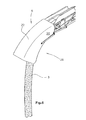
- Fig. 2 shows a arranged at a discharge end 12 of the conveyor 18 substantially in cross-section U-shaped shielding 6 with side panels 20 which project substantially vertically on both sides of a cover 22 of the shielding down.
- the shielding device 6 is in the Fig. 2 shown as a one-piece element. It is understood, however, that the shielding device 6 can also be designed in several parts, as in connection with the FIGS. 4a and 4b will be explained.
- the shielding device 6 is in Fig. 2 shown in its operating position 26, in which it encloses the material 3, which is dropped along a pitch parabola 9, without affecting the paravola 9 itself and without touching the Hauptgutstrom the material flow.
- the curvature of the cover 22 is therefore curved with a radius of curvature in the conveying direction 24, which is greater than or equal to the widest projecting parabola 9 at maximum conveying speed of the conveyor for the milled material 3.
- the shielding device 6 can ensure a shield even at low conveying speeds, it can be provided that the side parts 20 have a height which increases in the conveying direction downwards, as in the exemplary embodiment of FIG Fig. 6 shown.
- FIGS. 3a to 3c show different embodiments in which the shielding 6 of the in Fig. 2 shown operating position 26 has been transferred to a transport position 28.
- Fig. 3a a lateral pivoting of the shielding 6 about a substantially vertical axis or an axis orthogonal to the discharge end 12 of the conveyor 18 or about a substantially orthogonal to the loading surface at the discharge end 12 of the conveyor 18 extending axis.
- the shielding device 6 is pivoted laterally next to the discharge end 12 of the conveyor 18.
- Fig. 3b shows another embodiment in which the shielding 6 is pivotable about a substantially horizontal axis, preferably downwardly to be transferred to a transport position 28 and locked there.
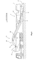
- Fig. 3c schematically shows an embodiment in which the shielding 6 is displaced against the conveyor 24 to the rear, z. B. by means of correspondingly shaped rail guides or by means of a four-bar mechanism, as in the FIGS. 5a, 5b and 6 shown.
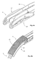
- Fig. 4a shows a multi-part shielding device 6, which consists either only of two laterally pivotable side parts 20, or as in Fig. 4b may additionally consist of a cover 22 in the operating position 26.
- the side parts 20 may in the embodiments of the FIGS. 4a and 4b , as in Fig. 6 shown, expand in the conveying direction to ensure lateral shielding even at the lowest conveying speed.
- the cover 22 may be formed of various materials, e.g. B. from a continuous sheet metal part or a screen plate or from a roll-up tissue, in particular a rubber fabric or a tarpaulin, wherein the cover can be transferred from the transport position 28 in an operating position 26 in the manner of a roller shutter along guides on the side panels 20.
- cover 22 may be designed to be displaceable or rollable, while the side parts are pivotable.
- the various embodiments of the shielding device 6 allow the shielding of external influences such as strong winds, so that they can not affect the trajectory along the parabola 9.
- the cover 22 upwards on the one hand does not affect the trajectory of Abschparabel and a contact with the milled material 3 basically avoids, but on the other hand, together with the side panels 20 is suitable for leaving the normally resulting parachute 9 of Hauptgutstroms by exclude individual particles as far as possible.
- Fig. 6 shows a pivotable about a four-bar linkage shielding 6 with downwardly extended side flaps 20 at a Hauptgutstrom with the lowest conveying speed of the conveyor 18th
Landscapes
- Engineering & Computer Science (AREA)
- Mining & Mineral Resources (AREA)
- Architecture (AREA)
- Civil Engineering (AREA)
- Structural Engineering (AREA)
- Mechanical Engineering (AREA)
- Road Repair (AREA)
- Disintegrating Or Milling (AREA)
- Excavating Of Shafts Or Tunnels (AREA)
Applications Claiming Priority (1)
| Application Number | Priority Date | Filing Date | Title |
|---|---|---|---|
| DE201310214675 DE102013214675A1 (de) | 2013-07-26 | 2013-07-26 | Selbstfahrende Straßenfräsmaschine, sowie Verfahren zum Abfräsen und Abtransportieren eines abgefrästen Materialstroms |
Publications (4)
| Publication Number | Publication Date |
|---|---|
| EP2835471A2 true EP2835471A2 (fr) | 2015-02-11 |
| EP2835471A3 EP2835471A3 (fr) | 2015-06-24 |
| EP2835471B1 EP2835471B1 (fr) | 2016-09-14 |
| EP2835471B2 EP2835471B2 (fr) | 2020-01-01 |
Family
ID=51176961
Family Applications (1)
| Application Number | Title | Priority Date | Filing Date |
|---|---|---|---|
| EP14176858.0A Active EP2835471B2 (fr) | 2013-07-26 | 2014-07-14 | Fraiseuse routière et procédé de fraisage et de transport du flux de matériau fraisé |
Country Status (4)
| Country | Link |
|---|---|
| US (2) | US9416500B2 (fr) |
| EP (1) | EP2835471B2 (fr) |
| CN (2) | CN104343074B (fr) |
| DE (1) | DE102013214675A1 (fr) |
Cited By (1)
| Publication number | Priority date | Publication date | Assignee | Title |
|---|---|---|---|---|
| EP2835471B1 (fr) | 2013-07-26 | 2016-09-14 | Wirtgen GmbH | Fraiseuse routière et procédé de fraisage et de transport du flux de matériau fraisé |
Families Citing this family (6)
| Publication number | Priority date | Publication date | Assignee | Title |
|---|---|---|---|---|
| USD774561S1 (en) * | 2014-01-24 | 2016-12-20 | Bomag Gmbh | Cold milling machine |
| USD774562S1 (en) * | 2014-07-22 | 2016-12-20 | Bomag Gmbh | Cold milling machine |
| US9719218B2 (en) | 2015-08-12 | 2017-08-01 | Caterpillar Paving Products Inc. | Cold planer secondary conveyor with adjusting discharge |
| DE102016223454A1 (de) * | 2016-11-25 | 2018-05-30 | Wirtgen Gmbh | System und Verfahren zum Nachverfolgen von Fräsgut |
| US10982397B2 (en) * | 2019-06-12 | 2021-04-20 | Caterpillar Paving Products Inc. | Milling rotor |
| CN115821711B (zh) * | 2022-11-01 | 2024-12-10 | 浙江江河建设有限公司 | 一种沥青路面的老化层剔除装置 |
Citations (2)
| Publication number | Priority date | Publication date | Assignee | Title |
|---|---|---|---|---|
| EP1507925A1 (fr) | 2002-05-28 | 2005-02-23 | WIRTGEN GmbH | Unite et procede d'aspiration pour eliminer la poussiere sur des fraiseuses |
| DE102012215013A1 (de) | 2012-08-23 | 2014-02-27 | Wirtgen Gmbh | Selbstfahrende Fräsmaschine, sowie Verfahren zum Abladen von Fräsgut |
Family Cites Families (8)
| Publication number | Priority date | Publication date | Assignee | Title |
|---|---|---|---|---|
| US4037391A (en) * | 1974-09-20 | 1977-07-26 | Harrington Manufacturing Company | Leaf guide means for tobacco harvester |
| US5505598A (en) * | 1994-07-29 | 1996-04-09 | Wirtgen America, Inc. | Milling machine with multi-width cutter |
| JP4453855B2 (ja) † | 2000-12-25 | 2010-04-21 | 株式会社小松製作所 | 破砕装置 |
| CN1184383C (zh) * | 2003-04-30 | 2005-01-12 | 长沙中联重工科技发展股份有限公司 | 路面铣刨机遇障保护方法及装置 |
| DE10323199A1 (de) † | 2003-05-22 | 2004-12-09 | Wolfgang Schmailzl | Transportfahrzeug mit Bankettfräseinrichtung |
| US8794867B2 (en) * | 2011-05-26 | 2014-08-05 | Trimble Navigation Limited | Asphalt milling machine control and method |
| CN102619158B (zh) * | 2012-04-17 | 2016-05-04 | 陕西长大实业有限公司 | 路面铣刨机 |
| DE102013214675A1 (de) | 2013-07-26 | 2015-01-29 | Wirtgen Gmbh | Selbstfahrende Straßenfräsmaschine, sowie Verfahren zum Abfräsen und Abtransportieren eines abgefrästen Materialstroms |
-
2013
- 2013-07-26 DE DE201310214675 patent/DE102013214675A1/de not_active Withdrawn
-
2014
- 2014-07-14 EP EP14176858.0A patent/EP2835471B2/fr active Active
- 2014-07-18 US US14/335,412 patent/US9416500B2/en active Active
- 2014-07-28 CN CN201410362578.1A patent/CN104343074B/zh active Active
- 2014-07-28 CN CN201420418896.0U patent/CN204039889U/zh not_active Withdrawn - After Issue
-
2016
- 2016-08-10 US US15/232,902 patent/US9938675B2/en active Active
Patent Citations (2)
| Publication number | Priority date | Publication date | Assignee | Title |
|---|---|---|---|---|
| EP1507925A1 (fr) | 2002-05-28 | 2005-02-23 | WIRTGEN GmbH | Unite et procede d'aspiration pour eliminer la poussiere sur des fraiseuses |
| DE102012215013A1 (de) | 2012-08-23 | 2014-02-27 | Wirtgen Gmbh | Selbstfahrende Fräsmaschine, sowie Verfahren zum Abladen von Fräsgut |
Cited By (1)
| Publication number | Priority date | Publication date | Assignee | Title |
|---|---|---|---|---|
| EP2835471B1 (fr) | 2013-07-26 | 2016-09-14 | Wirtgen GmbH | Fraiseuse routière et procédé de fraisage et de transport du flux de matériau fraisé |
Also Published As
| Publication number | Publication date |
|---|---|
| US20150028653A1 (en) | 2015-01-29 |
| CN204039889U (zh) | 2014-12-24 |
| US9416500B2 (en) | 2016-08-16 |
| CN104343074B (zh) | 2017-04-12 |
| EP2835471A3 (fr) | 2015-06-24 |
| EP2835471B1 (fr) | 2016-09-14 |
| US9938675B2 (en) | 2018-04-10 |
| DE102013214675A1 (de) | 2015-01-29 |
| EP2835471B2 (fr) | 2020-01-01 |
| US20170030032A1 (en) | 2017-02-02 |
| CN104343074A (zh) | 2015-02-11 |
Similar Documents
| Publication | Publication Date | Title |
|---|---|---|
| EP2835471B1 (fr) | Fraiseuse routière et procédé de fraisage et de transport du flux de matériau fraisé | |
| EP1507925B1 (fr) | Unite et procede d'aspiration pour eliminer la poussiere sur des fraiseuses | |
| DE102006062129B4 (de) | Straßenbaumaschine sowie Verfahren zur Messung der Frästiefe | |
| EP2886720B1 (fr) | Engin et procédé de fraisage et de transport d'un flux de matériau enlevé à l'aide d'un engin | |
| DE102012018918B4 (de) | Abstreifvorrichtung für Fräswalzen einer Baumaschine und Baumaschine | |
| DE2550391A1 (de) | Verfahren zum entnehmen von bettungsmaterial aus schotterbettungen | |
| DE4343148C2 (de) | Fahrbare Gleisbett-Bearbeitungsmaschine | |
| DE102018127560A1 (de) | Materialabweiser für eine bodenfräsmaschine | |
| EP4092191A1 (fr) | Engin de construction routière pourvu de dispositif à barrière d'air et procédé | |
| DE19832787B4 (de) | Selbstfahrender Kompostumsetzer | |
| EP0824164B1 (fr) | Machine de construction pour voie ferrée pour enlever le ballast | |
| CH616472A5 (fr) | ||
| AT508499B1 (de) | Vortriebsmaschine | |
| DE102021119491A1 (de) | BODENFRÄSMASCHINE, INSBESONDERE STRAßENFRÄSE, MIT EINER FÖRDEREINRICHTUNG ZUM TRANSPORT VON FRÄSGUT SOWIE VERFAHREN ZUM FÖRDERN VON FRÄSGUT EINER BODENFRÄSMASCHINE | |
| DD158116A5 (de) | Gleisbaumaschinen mit einer schotterbrett-raeum-und planiervorrichtung | |
| DE3151030C2 (fr) | ||
| DE2927256C2 (fr) | ||
| AT520040B1 (de) | Schienenfahrzeug zur Gleisoberbausanierung | |
| EP0663472A1 (fr) | Dispositif de nettoyage d'un lit de ballast d'un chemin de fer | |
| EP2168692B1 (fr) | Dispositif de séparation pour des matériaux de chargement | |
| DE3223350C2 (de) | Fahrbare Gleisbearbeitungsmaschine | |
| DE102022112640B3 (de) | Aufbereitungsanlage | |
| EP2599682B1 (fr) | Dispositif de protection pour un composant sur la face inférieure d'un véhicule sur rails | |
| EP4617429A1 (fr) | Finisseuse de route dotée d'une tôle de raclage réglable en hauteur | |
| DE102021118785A1 (de) | BODENFRÄSMASCHINE, INSBESONDERE STRAßENFRÄSE, SOWIE VERFAHREN ZUM ERHALT EINES REINIGUNGSZUGRIFFS ZU EINEM VON EINER ÜBERGABEBEREICHSABDECKUNG WENIGSTENS TEILWEISE ZUR AUßENSEITE HIN ABGEDICHTETEN INNENRAUM EINES MATERIALÜBERGABEBEREICHES EINER BODENFRÄSMASCHINE |
Legal Events
| Date | Code | Title | Description |
|---|---|---|---|
| PUAI | Public reference made under article 153(3) epc to a published international application that has entered the european phase |
Free format text: ORIGINAL CODE: 0009012 |
|
| 17P | Request for examination filed |
Effective date: 20140714 |
|
| AK | Designated contracting states |
Kind code of ref document: A2 Designated state(s): AL AT BE BG CH CY CZ DE DK EE ES FI FR GB GR HR HU IE IS IT LI LT LU LV MC MK MT NL NO PL PT RO RS SE SI SK SM TR |
|
| AX | Request for extension of the european patent |
Extension state: BA ME |
|
| PUAL | Search report despatched |
Free format text: ORIGINAL CODE: 0009013 |
|
| AK | Designated contracting states |
Kind code of ref document: A3 Designated state(s): AL AT BE BG CH CY CZ DE DK EE ES FI FR GB GR HR HU IE IS IT LI LT LU LV MC MK MT NL NO PL PT RO RS SE SI SK SM TR |
|
| AX | Request for extension of the european patent |
Extension state: BA ME |
|
| RIC1 | Information provided on ipc code assigned before grant |
Ipc: E01C 23/088 20060101AFI20150521BHEP Ipc: E01C 23/12 20060101ALI20150521BHEP Ipc: B65G 21/08 20060101ALI20150521BHEP |
|
| R17P | Request for examination filed (corrected) |
Effective date: 20151216 |
|
| RBV | Designated contracting states (corrected) |
Designated state(s): AL AT BE BG CH CY CZ DE DK EE ES FI FR GB GR HR HU IE IS IT LI LT LU LV MC MK MT NL NO PL PT RO RS SE SI SK SM TR |
|
| GRAP | Despatch of communication of intention to grant a patent |
Free format text: ORIGINAL CODE: EPIDOSNIGR1 |
|
| RIC1 | Information provided on ipc code assigned before grant |
Ipc: E01C 23/12 20060101ALI20160208BHEP Ipc: B65G 21/08 20060101ALI20160208BHEP Ipc: E01C 23/088 20060101AFI20160208BHEP |
|
| INTG | Intention to grant announced |
Effective date: 20160303 |
|
| GRAS | Grant fee paid |
Free format text: ORIGINAL CODE: EPIDOSNIGR3 |
|
| GRAA | (expected) grant |
Free format text: ORIGINAL CODE: 0009210 |
|
| AK | Designated contracting states |
Kind code of ref document: B1 Designated state(s): AL AT BE BG CH CY CZ DE DK EE ES FI FR GB GR HR HU IE IS IT LI LT LU LV MC MK MT NL NO PL PT RO RS SE SI SK SM TR |
|
| REG | Reference to a national code |
Ref country code: GB Ref legal event code: FG4D Free format text: NOT ENGLISH |
|
| REG | Reference to a national code |
Ref country code: CH Ref legal event code: EP |
|
| REG | Reference to a national code |
Ref country code: IE Ref legal event code: FG4D Free format text: LANGUAGE OF EP DOCUMENT: GERMAN |
|
| REG | Reference to a national code |
Ref country code: AT Ref legal event code: REF Ref document number: 829144 Country of ref document: AT Kind code of ref document: T Effective date: 20161015 |
|
| REG | Reference to a national code |
Ref country code: DE Ref legal event code: R096 Ref document number: 502014001436 Country of ref document: DE |
|
| REG | Reference to a national code |
Ref country code: SE Ref legal event code: TRGR |
|
| REG | Reference to a national code |
Ref country code: LT Ref legal event code: MG4D |
|
| REG | Reference to a national code |
Ref country code: NL Ref legal event code: MP Effective date: 20160914 |
|
| PG25 | Lapsed in a contracting state [announced via postgrant information from national office to epo] |
Ref country code: LT Free format text: LAPSE BECAUSE OF FAILURE TO SUBMIT A TRANSLATION OF THE DESCRIPTION OR TO PAY THE FEE WITHIN THE PRESCRIBED TIME-LIMIT Effective date: 20160914 Ref country code: NO Free format text: LAPSE BECAUSE OF FAILURE TO SUBMIT A TRANSLATION OF THE DESCRIPTION OR TO PAY THE FEE WITHIN THE PRESCRIBED TIME-LIMIT Effective date: 20161214 Ref country code: HR Free format text: LAPSE BECAUSE OF FAILURE TO SUBMIT A TRANSLATION OF THE DESCRIPTION OR TO PAY THE FEE WITHIN THE PRESCRIBED TIME-LIMIT Effective date: 20160914 Ref country code: FI Free format text: LAPSE BECAUSE OF FAILURE TO SUBMIT A TRANSLATION OF THE DESCRIPTION OR TO PAY THE FEE WITHIN THE PRESCRIBED TIME-LIMIT Effective date: 20160914 Ref country code: RS Free format text: LAPSE BECAUSE OF FAILURE TO SUBMIT A TRANSLATION OF THE DESCRIPTION OR TO PAY THE FEE WITHIN THE PRESCRIBED TIME-LIMIT Effective date: 20160914 |
|
| PG25 | Lapsed in a contracting state [announced via postgrant information from national office to epo] |
Ref country code: NL Free format text: LAPSE BECAUSE OF FAILURE TO SUBMIT A TRANSLATION OF THE DESCRIPTION OR TO PAY THE FEE WITHIN THE PRESCRIBED TIME-LIMIT Effective date: 20160914 Ref country code: LV Free format text: LAPSE BECAUSE OF FAILURE TO SUBMIT A TRANSLATION OF THE DESCRIPTION OR TO PAY THE FEE WITHIN THE PRESCRIBED TIME-LIMIT Effective date: 20160914 Ref country code: GR Free format text: LAPSE BECAUSE OF FAILURE TO SUBMIT A TRANSLATION OF THE DESCRIPTION OR TO PAY THE FEE WITHIN THE PRESCRIBED TIME-LIMIT Effective date: 20161215 |
|
| PG25 | Lapsed in a contracting state [announced via postgrant information from national office to epo] |
Ref country code: EE Free format text: LAPSE BECAUSE OF FAILURE TO SUBMIT A TRANSLATION OF THE DESCRIPTION OR TO PAY THE FEE WITHIN THE PRESCRIBED TIME-LIMIT Effective date: 20160914 Ref country code: RO Free format text: LAPSE BECAUSE OF FAILURE TO SUBMIT A TRANSLATION OF THE DESCRIPTION OR TO PAY THE FEE WITHIN THE PRESCRIBED TIME-LIMIT Effective date: 20160914 |
|
| PG25 | Lapsed in a contracting state [announced via postgrant information from national office to epo] |
Ref country code: IS Free format text: LAPSE BECAUSE OF FAILURE TO SUBMIT A TRANSLATION OF THE DESCRIPTION OR TO PAY THE FEE WITHIN THE PRESCRIBED TIME-LIMIT Effective date: 20170114 Ref country code: ES Free format text: LAPSE BECAUSE OF FAILURE TO SUBMIT A TRANSLATION OF THE DESCRIPTION OR TO PAY THE FEE WITHIN THE PRESCRIBED TIME-LIMIT Effective date: 20160914 Ref country code: PL Free format text: LAPSE BECAUSE OF FAILURE TO SUBMIT A TRANSLATION OF THE DESCRIPTION OR TO PAY THE FEE WITHIN THE PRESCRIBED TIME-LIMIT Effective date: 20160914 Ref country code: SM Free format text: LAPSE BECAUSE OF FAILURE TO SUBMIT A TRANSLATION OF THE DESCRIPTION OR TO PAY THE FEE WITHIN THE PRESCRIBED TIME-LIMIT Effective date: 20160914 Ref country code: CZ Free format text: LAPSE BECAUSE OF FAILURE TO SUBMIT A TRANSLATION OF THE DESCRIPTION OR TO PAY THE FEE WITHIN THE PRESCRIBED TIME-LIMIT Effective date: 20160914 Ref country code: SK Free format text: LAPSE BECAUSE OF FAILURE TO SUBMIT A TRANSLATION OF THE DESCRIPTION OR TO PAY THE FEE WITHIN THE PRESCRIBED TIME-LIMIT Effective date: 20160914 Ref country code: BG Free format text: LAPSE BECAUSE OF FAILURE TO SUBMIT A TRANSLATION OF THE DESCRIPTION OR TO PAY THE FEE WITHIN THE PRESCRIBED TIME-LIMIT Effective date: 20161214 Ref country code: PT Free format text: LAPSE BECAUSE OF FAILURE TO SUBMIT A TRANSLATION OF THE DESCRIPTION OR TO PAY THE FEE WITHIN THE PRESCRIBED TIME-LIMIT Effective date: 20170116 |
|
| REG | Reference to a national code |
Ref country code: DE Ref legal event code: R026 Ref document number: 502014001436 Country of ref document: DE |
|
| PLBI | Opposition filed |
Free format text: ORIGINAL CODE: 0009260 |
|
| PLAX | Notice of opposition and request to file observation + time limit sent |
Free format text: ORIGINAL CODE: EPIDOSNOBS2 |
|
| REG | Reference to a national code |
Ref country code: FR Ref legal event code: PLFP Year of fee payment: 4 |
|
| 26 | Opposition filed |
Opponent name: CATERPILLAR INC. Effective date: 20170614 |
|
| PG25 | Lapsed in a contracting state [announced via postgrant information from national office to epo] |
Ref country code: DK Free format text: LAPSE BECAUSE OF FAILURE TO SUBMIT A TRANSLATION OF THE DESCRIPTION OR TO PAY THE FEE WITHIN THE PRESCRIBED TIME-LIMIT Effective date: 20160914 |
|
| PG25 | Lapsed in a contracting state [announced via postgrant information from national office to epo] |
Ref country code: SI Free format text: LAPSE BECAUSE OF FAILURE TO SUBMIT A TRANSLATION OF THE DESCRIPTION OR TO PAY THE FEE WITHIN THE PRESCRIBED TIME-LIMIT Effective date: 20160914 |
|
| PLBB | Reply of patent proprietor to notice(s) of opposition received |
Free format text: ORIGINAL CODE: EPIDOSNOBS3 |
|
| REG | Reference to a national code |
Ref country code: CH Ref legal event code: PL |
|
| REG | Reference to a national code |
Ref country code: IE Ref legal event code: MM4A |
|
| PG25 | Lapsed in a contracting state [announced via postgrant information from national office to epo] |
Ref country code: LI Free format text: LAPSE BECAUSE OF NON-PAYMENT OF DUE FEES Effective date: 20170731 Ref country code: IE Free format text: LAPSE BECAUSE OF NON-PAYMENT OF DUE FEES Effective date: 20170714 Ref country code: CH Free format text: LAPSE BECAUSE OF NON-PAYMENT OF DUE FEES Effective date: 20170731 |
|
| REG | Reference to a national code |
Ref country code: BE Ref legal event code: MM Effective date: 20170731 |
|
| PG25 | Lapsed in a contracting state [announced via postgrant information from national office to epo] |
Ref country code: LU Free format text: LAPSE BECAUSE OF NON-PAYMENT OF DUE FEES Effective date: 20170714 |
|
| REG | Reference to a national code |
Ref country code: FR Ref legal event code: PLFP Year of fee payment: 5 |
|
| PG25 | Lapsed in a contracting state [announced via postgrant information from national office to epo] |
Ref country code: BE Free format text: LAPSE BECAUSE OF NON-PAYMENT OF DUE FEES Effective date: 20170731 |
|
| PG25 | Lapsed in a contracting state [announced via postgrant information from national office to epo] |
Ref country code: MT Free format text: LAPSE BECAUSE OF FAILURE TO SUBMIT A TRANSLATION OF THE DESCRIPTION OR TO PAY THE FEE WITHIN THE PRESCRIBED TIME-LIMIT Effective date: 20160914 |
|
| PG25 | Lapsed in a contracting state [announced via postgrant information from national office to epo] |
Ref country code: AL Free format text: LAPSE BECAUSE OF FAILURE TO SUBMIT A TRANSLATION OF THE DESCRIPTION OR TO PAY THE FEE WITHIN THE PRESCRIBED TIME-LIMIT Effective date: 20160914 |
|
| PG25 | Lapsed in a contracting state [announced via postgrant information from national office to epo] |
Ref country code: HU Free format text: LAPSE BECAUSE OF FAILURE TO SUBMIT A TRANSLATION OF THE DESCRIPTION OR TO PAY THE FEE WITHIN THE PRESCRIBED TIME-LIMIT; INVALID AB INITIO Effective date: 20140714 Ref country code: MC Free format text: LAPSE BECAUSE OF FAILURE TO SUBMIT A TRANSLATION OF THE DESCRIPTION OR TO PAY THE FEE WITHIN THE PRESCRIBED TIME-LIMIT Effective date: 20160914 |
|
| PG25 | Lapsed in a contracting state [announced via postgrant information from national office to epo] |
Ref country code: CY Free format text: LAPSE BECAUSE OF FAILURE TO SUBMIT A TRANSLATION OF THE DESCRIPTION OR TO PAY THE FEE WITHIN THE PRESCRIBED TIME-LIMIT Effective date: 20160914 |
|
| PG25 | Lapsed in a contracting state [announced via postgrant information from national office to epo] |
Ref country code: MK Free format text: LAPSE BECAUSE OF FAILURE TO SUBMIT A TRANSLATION OF THE DESCRIPTION OR TO PAY THE FEE WITHIN THE PRESCRIBED TIME-LIMIT Effective date: 20160914 |
|
| PUAH | Patent maintained in amended form |
Free format text: ORIGINAL CODE: 0009272 |
|
| STAA | Information on the status of an ep patent application or granted ep patent |
Free format text: STATUS: PATENT MAINTAINED AS AMENDED |
|
| 27A | Patent maintained in amended form |
Effective date: 20200101 |
|
| AK | Designated contracting states |
Kind code of ref document: B2 Designated state(s): AL AT BE BG CH CY CZ DE DK EE ES FI FR GB GR HR HU IE IS IT LI LT LU LV MC MK MT NL NO PL PT RO RS SE SI SK SM TR |
|
| REG | Reference to a national code |
Ref country code: DE Ref legal event code: R102 Ref document number: 502014001436 Country of ref document: DE |
|
| PG25 | Lapsed in a contracting state [announced via postgrant information from national office to epo] |
Ref country code: TR Free format text: LAPSE BECAUSE OF FAILURE TO SUBMIT A TRANSLATION OF THE DESCRIPTION OR TO PAY THE FEE WITHIN THE PRESCRIBED TIME-LIMIT Effective date: 20160914 |
|
| REG | Reference to a national code |
Ref country code: SE Ref legal event code: RPEO |
|
| REG | Reference to a national code |
Ref country code: AT Ref legal event code: MM01 Ref document number: 829144 Country of ref document: AT Kind code of ref document: T Effective date: 20190714 |
|
| PG25 | Lapsed in a contracting state [announced via postgrant information from national office to epo] |
Ref country code: AT Free format text: LAPSE BECAUSE OF NON-PAYMENT OF DUE FEES Effective date: 20190714 |
|
| P01 | Opt-out of the competence of the unified patent court (upc) registered |
Effective date: 20230525 |
|
| PGFP | Annual fee paid to national office [announced via postgrant information from national office to epo] |
Ref country code: DE Payment date: 20250722 Year of fee payment: 12 |
|
| PGFP | Annual fee paid to national office [announced via postgrant information from national office to epo] |
Ref country code: IT Payment date: 20250731 Year of fee payment: 12 |
|
| PGFP | Annual fee paid to national office [announced via postgrant information from national office to epo] |
Ref country code: GB Payment date: 20250724 Year of fee payment: 12 |
|
| PGFP | Annual fee paid to national office [announced via postgrant information from national office to epo] |
Ref country code: FR Payment date: 20250723 Year of fee payment: 12 |
|
| PGFP | Annual fee paid to national office [announced via postgrant information from national office to epo] |
Ref country code: SE Payment date: 20250723 Year of fee payment: 12 |