EP4092191A1 - Engin de construction routière pourvu de dispositif à barrière d'air et procédé - Google Patents
Engin de construction routière pourvu de dispositif à barrière d'air et procédé Download PDFInfo
- Publication number
- EP4092191A1 EP4092191A1 EP21174880.1A EP21174880A EP4092191A1 EP 4092191 A1 EP4092191 A1 EP 4092191A1 EP 21174880 A EP21174880 A EP 21174880A EP 4092191 A1 EP4092191 A1 EP 4092191A1
- Authority
- EP
- European Patent Office
- Prior art keywords
- air
- construction machine
- road construction
- driver
- barrier device
- Prior art date
- Legal status (The legal status is an assumption and is not a legal conclusion. Google has not performed a legal analysis and makes no representation as to the accuracy of the status listed.)
- Granted
Links
Images
Classifications
-
- E—FIXED CONSTRUCTIONS
- E01—CONSTRUCTION OF ROADS, RAILWAYS, OR BRIDGES
- E01C—CONSTRUCTION OF, OR SURFACES FOR, ROADS, SPORTS GROUNDS, OR THE LIKE; MACHINES OR AUXILIARY TOOLS FOR CONSTRUCTION OR REPAIR
- E01C19/00—Machines, tools or auxiliary devices for preparing or distributing paving materials, for working the placed materials, or for forming, consolidating, or finishing the paving
- E01C19/48—Machines, tools or auxiliary devices for preparing or distributing paving materials, for working the placed materials, or for forming, consolidating, or finishing the paving for laying-down the materials and consolidating them, or finishing the surface, e.g. slip forms therefor, forming kerbs or gutters in a continuous operation in situ
- E01C19/488—Machines, tools or auxiliary devices for preparing or distributing paving materials, for working the placed materials, or for forming, consolidating, or finishing the paving for laying-down the materials and consolidating them, or finishing the surface, e.g. slip forms therefor, forming kerbs or gutters in a continuous operation in situ with rollers for consolidating or finishing combined with tamping, vibrating, pressing or smoothing consolidation or finishing means
-
- E—FIXED CONSTRUCTIONS
- E01—CONSTRUCTION OF ROADS, RAILWAYS, OR BRIDGES
- E01C—CONSTRUCTION OF, OR SURFACES FOR, ROADS, SPORTS GROUNDS, OR THE LIKE; MACHINES OR AUXILIARY TOOLS FOR CONSTRUCTION OR REPAIR
- E01C19/00—Machines, tools or auxiliary devices for preparing or distributing paving materials, for working the placed materials, or for forming, consolidating, or finishing the paving
- E01C19/48—Machines, tools or auxiliary devices for preparing or distributing paving materials, for working the placed materials, or for forming, consolidating, or finishing the paving for laying-down the materials and consolidating them, or finishing the surface, e.g. slip forms therefor, forming kerbs or gutters in a continuous operation in situ
-
- E—FIXED CONSTRUCTIONS
- E01—CONSTRUCTION OF ROADS, RAILWAYS, OR BRIDGES
- E01C—CONSTRUCTION OF, OR SURFACES FOR, ROADS, SPORTS GROUNDS, OR THE LIKE; MACHINES OR AUXILIARY TOOLS FOR CONSTRUCTION OR REPAIR
- E01C2301/00—Machine characteristics, parts or accessories not otherwise provided for
- E01C2301/30—Cabin details
-
- E—FIXED CONSTRUCTIONS
- E01—CONSTRUCTION OF ROADS, RAILWAYS, OR BRIDGES
- E01C—CONSTRUCTION OF, OR SURFACES FOR, ROADS, SPORTS GROUNDS, OR THE LIKE; MACHINES OR AUXILIARY TOOLS FOR CONSTRUCTION OR REPAIR
- E01C2301/00—Machine characteristics, parts or accessories not otherwise provided for
- E01C2301/50—Methods or devices for preventing dust by spraying or sucking
Definitions
- the present invention relates to a road construction machine, in particular a road finisher or a feeder vehicle for a road finisher, according to claim 1.
- the invention also relates to a method for generating an air flow according to claim 15.
- vapors and bituminous aerosols can arise in the immediate vicinity of the road finisher or feeder vehicle. They can be caused in particular when hot paving material is being transported or installed.
- EP 0 843 044 A1 discloses a road finisher and a feeder with an extraction system which is designed to extract vapors and aerosols from an area above the auger positioned in front of the screed and to eject them above the driver's canopy of a driver's operating platform. Furthermore, the extraction system is designed to extract vapors from a bunker area for installation material and eject them above the roof structure. On the feeder vehicle, the extraction system can on the one hand extract vapors and aerosols that arise in the goods bunker area, as well as vapors and aerosols that arise along a conveyor device of the feeder, and eject them above the roof structure in order to reduce the concentration of vapors and aerosols in the area around the feeder vehicle.
- DE 10 2012 007 869 A1 also discloses a road finisher with a suction device, by means of which vapors and aerosols can be sucked off along a longitudinal transport device for paving material, which runs below the driver's control station within the chassis, and can be introduced into an exhaust gas emission system, so that the vapors end up together with exhaust gases from above the driver's canopy exhaust pipe to be blown out into the environment.
- JP 2014-139 388 A discloses a further suction system which is designed to suction from an area of the transverse distributor, which laterally distributes the paving material in front of the screed, and to eject it above a driver's operating area.
- the above suction devices are designed to suck off vapors and/or aerosols at the point of origin and above on road finishers or feeder vehicles of a roof structure or above an operating platform set up for the driver.
- the disadvantage of this is that experience has shown that the performance of these extraction systems is not entirely sufficient to prevent vapors and/or aerosols from penetrating the driver's operating area or other operating areas provided on the road finisher or feeder that are intended for an operator.
- WO 2013/185867 A1 discloses a suction device, the suction opening of which is assigned to an area of the transverse distribution auger of a road finisher, with a blowing device for forming an air flushing horizontally covering the suction flow also being provided above the area of material distribution.
- JP 2014-139 389 A discloses a road finisher with a blowing device positioned at the front of an engine compartment cover, which generates a forward-directed air flow above a material bunker in the direction of travel of the road finisher, with which the rising vapors and/or aerosols from the material bunker can be covered.
- DE 10 2020 123 723 A1 discloses a road finisher which, viewed in the production direction, has at least one air nozzle unit in front of the screed for generating a vertical and/or horizontal air curtain, with the air curtain produced by means of the air nozzle unit delimiting the area between a first side plate and a second side plate of the screed, so that vapors from the Paving material from this area can be better sucked off by a suction device.
- Such an air curtain has the same technical effect as a horizontal or vertical cover around the area of the auger.
- DE 10 2020 123 723 A1 an air nozzle unit, which is arranged at a control station of the paver to create an air curtain around the control station so that vapors cannot reach the area of the control station.
- the object of the invention is to provide a road construction machine, in particular a road finisher or a feeder vehicle for a road finisher, with which vapors and/or aerosols can be kept away from the operating personnel of the road construction machine even better. Furthermore, it is the object of the invention to provide a corresponding method.
- the invention relates to a road construction machine which is designed in particular in the form of a road finisher or feeder vehicle for a road finisher.
- the road construction machine according to the invention comprises at least one driver's control platform for a driver of the road construction machine and/or an external control station for an operator of the road construction machine.
- the road construction machine according to the invention has at least one first air barrier device for the driver of the road construction machine and/or at least one second air barrier device for the operator of the external control panel of the road construction machine.
- the road construction machine according to the invention comprises a material bunker arranged in front of the driver's operating platform in the direction of travel, with lateral material bunker halves for receiving a paving material.
- the invention is characterized in that, viewed from above, the first air barrier device for generating at least one directed air flow in the form of an air wall extending within an area to the side of the driver's operating platform and/or that the second air barrier device for generating at least one air flow within an area to the side of the outside operator's platform present range extending, directed air flow is formed in the form of an air wall.
- the areas mentioned above are located to the side of the actual geometry of the road construction machine when viewed from above and are often used by the driver and/or operator in practice to control and/or monitor the operation of the road construction machine from there.
- the air wall formed within these outer regions in the invention provides an air barrier to isolate the driver and/or operator from vapors and/or aerosols. Furthermore, the air flow used to generate the air wall can provide a suction effect for transporting away air that may be contaminated with vapors and/or aerosols.
- the driver's operating platform can have open outer sides when viewed in the direction of travel. Vapors and/or aerosols can conventionally be drawn into the area of the driver's operating platform through these open outer sides.
- the air wall according to the invention can be designed in such a way next to the driver's operating platform, i.e. within a laterally adjacent zone of the driver's operating platform, that vapors and/or aerosols can be better kept away from the open outer sides.
- the air wall generated outside of the driver's operating platform by means of the first air barrier device makes it possible, in particular, to seal off the area lying to the side of the driver's operating platform Area in front of the bunker, especially from the lateral halves of the bunker, rising vapors and/or aerosols.
- this positive foreclosure effect for the driver of the road construction machine occurs when he is positioned to the side of the driver's control platform, for example when the driver's seat console he uses is swung out to the side, beyond the driver's control platform, which means that the driver himself is within this zone, i.e. to the side positioned on the driver's control platform.
- the air wall created by the second air barrier device next to the outside control station offers an operator positioned to the side of the outside control station a comparable sealing effect against rising vapors and/or aerosols as the first air barrier device to the side of the driver's operating platform. Above all, vapors and/or aerosols from a transverse distribution channel can thus be better kept away from the operator.
- an air wall formed in these zones is special for them effective for sealing off rising vapors and/or aerosols.
- the air wall generated by means of the first and/or by means of the second air barrier device is preferably designed as an air wall that intersects the direction of travel of the road construction machine.
- the air flow for generating the air wall can be blown out from the road construction machine transversely to the direction of travel or at a predetermined angle to the side. This achieves a double effect.
- the air wall designed in this way as such can excellently shield a driver and/or operator positioned within the side zones, ie a driver and/or operator positioned next to the driver's control platform and/or next to the outside control station, from rising vapors and/or aerosols.
- Such an air wall forms, so to speak, an air curtain for the driver and/or the operator of the road construction machine, which serves to at least reduce vapors and/or aerosols in the area in which it is located at the side.
- the air flow that is expelled outwards from the road construction machine or tends to be angled forwards can transport aerosols and/or vapors sideways away from the driver and/or operator.
- the air wall created is next to the Driver's control platform and/or next to the outside control station within adjoining zones at an angle of between 30° and 60° to the direction of travel.
- the first air barrier device comprises at least one nozzle arranged on a roof segment that can be extended transversely to the direction of travel, at least one nozzle arranged on a driver's seat console that can be pivoted sideways to the driver's operating platform, at least one nozzle arranged on an A-pillar of a roof structure and/or at least one Nozzle arranged on the bunker halves to generate the air wall.
- the area to the side of the driver's operating platform can be effectively sealed off from rising vapors and/or aerosols.
- the nozzle of the first air barrier device is formed integrally on a component of the extendable roof segment.
- the nozzle is arranged on a carrier of the extendable roof segment that faces the material bunker, for example in the form of a blowing strip, which extends essentially along the carrier.
- the air wall that can be generated from top to bottom within the area on the side of the driver's operating platform by means of this blowing bar is essentially transverse to the direction of travel of the road construction machine and can protect a driver positioned behind, outside of the driver's operating platform or on the driver's operating platform from vapors rising from the bunker area and/or Shield aerosols.
- the nozzle of the first air barrier device is preferably formed integrally on a substructure of the driver's seat console, for example on a floor panel, and/or integrally on a fall-out protection of the driver's seat console, for example within a railing section. This ensures that the air wall that can be generated by means of the nozzle is assigned directly to the driver's seat console and thus to the driver sitting on it for shielding from vapors and/or aerosols, especially when the driver's seat console is swung out laterally beyond the driver's operating platform.
- the nozzle would be possible, for example, for the nozzle to run along an outer edge of the substructure at the front in the direction of travel or to be designed as part of an upper railing section of the fall-out protection, for example in the form of a cylindrical tube with a number of blow-out openings that serve to generate the directed air flow.
- the nozzle of the first air barrier device is designed to be integrated within the A pillar, so that the A pillar forms a housing for the nozzle.
- the A pillar is designed in the form of a hollow profile, with the nozzle extending in the form of a pipeline at least in sections within the A pillar.
- nozzle blow-out openings be aligned with exhaust ports formed in the A-pillar to create the air wall of the invention to protect the driver from rising vapors and/or aerosols.
- the first air barrier device preferably comprises a first nozzle fitted along the A pillar and a second nozzle fitted along a B pillar positioned behind the A pillar in the direction of travel, so that the two air walls generated by these nozzles at a distance from one another have a side of the driver's operating platform for train the driver positioned in this zone at least to the front and to the rear with limited air ducts.
- the driver can be shielded from both vapors and/or aerosols from the material bunker area and from vapors and/or aerosols rising from a transverse distribution duct behind him in the direction of travel, especially when he is positioned on the driver's seat console to the side of the driver's operating platform.
- An advantageous embodiment of the invention provides that the nozzle of the first air barrier device is formed within an upper edge of the half of the material bunker. In this way, vapors and/or aerosols escalating from an outer area of the halves of the material bunker can be shielded directly at the upper edge of the material bunker.
- the nozzle preferably extends at least in sections along an upper edge of a rear wall of the half of the crop bunker and/or at least in sections along an upper edge of an outer wall of the half of the crop bunker in order to advantageously intercept, dilute and remove the vapors and/or aerosols rising from the outer area of the crop bunker to transport.
- the air wall thus generated functionally forms an extension on the rear wall of the bunker and/or on the outer wall of the bunker and can form an air drop side that extends beyond the bunker wall made of metal. In this way, vapors and/or aerosols from the material bunker can both be shielded better and transported away better above a height level of the driver and other operators working in the area of the road construction machine.
- the first air barrier device or at least one fan device that is provided on the road construction machine and supports the first air barrier device is designed to generate at least one directed air flow in the direction of travel that is assigned at least in sections along a front area of the driver's operating platform in the form of an air wall.
- This air wall can extend in the direction of travel directly in front of the driver's operating platform and in particular protrude as an air barrier from the driver's operating platform.
- the air flow formed along the front area of the driver's operating platform preferably has the same flow direction as the air flow generated by means of the first air barrier device for generating the air flow within the area present at the side of the driver's operating platform.
- the two air flows can be controlled in such a way that they merge into one another across areas, resulting in an enlarged, closed air barrier for the driver of the road construction machine.
- the airflow formed in front of the driver's operating platform could be directed transversely to the direction of travel in order to entrain air that may be contaminated with aerosols and/or vapors sideways from the front area of the driver's operating platform.
- polluted air can be pushed sideways out of the driver's area.
- This further improves the air quality in the area of the driver's operating platform.
- a nozzle could be used, for example, which is attached at least in sections along the A-pillar and is preferably integrated therein. The air flow generated by means of this nozzle can extend transversely from the A pillar having the nozzle in the form of an air wall to a further A pillar arranged offset to the side.
- the air wall generated in front of the driver's operating platform could be formed by an upwardly directed airflow flowing out of an engine cover part adjacent to the front area of the driver's operating platform.
- an air flow which is preferably directed vertically upwards, can entrain polluted air upwards, i.e. transport it away to an area above the operator.
- the air flow formed in front of the driver's operating platform is in the form of an air wall formed directly behind a windshield in the direction of travel.
- the windscreen can thus be defogged and, on the other hand, it can also serve as a guide geometry for the air flow.
- an air wall running essentially parallel to the windscreen and formed directly behind it has the advantage that the driver on the driver's operating platform is not blown on as a result.
- the second air barrier device preferably has at least one nozzle arranged on a side slide of the outside control station for generating the air wall and/or at least one nozzle arranged on a roof of the outside control station for generating the air wall.
- the nozzle could be in the form of a substantially vertical blowing bar, offset laterally in the direction of travel relative to the outside control station to create an air wall in the adjacent area to shield vapors and/or aerosols.
- the nozzle located on the canopy of the outside control station is positioned along a cross-directional front beam of the canopy to form a top-down curtain of air to the side of the outside station immediately in front of an operator positioned below.
- the second air barrier device has at least one nozzle arranged on a rear wall of the screed for generating an upward air flow and/or at least one nozzle arranged below a screed walkway for generating an air flow directed counter to the direction of travel of the road construction machine.
- Such nozzles can effectively supplement the air wall generated by the second air barrier device on the side of the outside control station in order to additionally protect the operator of the outside control station from rising vapors and/or aerosols, even if he changes sides of the screed via the catwalk attached to the rear wall of the screed.
- a nozzle arranged below the screed walkway would have the advantage that the air wall thus generated could spread out like a carpet above a newly laid paving course, which means that vapors and/or aerosols can be retained on the surface of the newly laid paving course.
- the nozzle arranged along the rear wall of the screed and/or the nozzle arranged below the screed catwalk can generate an air flow that can be dynamically adjusted depending on a distance measurement to a following compactor vehicle, for example to a roller.
- the air flow produced by means of these nozzles could be automatically increased in order to better protect the driver of the following compactor vehicle from rising aerosols and/or vapors.
- the first and/or the second air barrier device can be operated using a fan configured in the engine compartment of the road construction machine to generate a flow of cooling air and/or comprises at least one filter unit for cleaning the air conveyed therein.
- a fan thus fulfills a dual function in that it can be used on the one hand to drive the cooling air flow to dissipate heat in the area of the motor and on the other hand as a drive for the first and/or second air barrier device.
- a volume flow generated by means of the first and/or the second air barrier device can be varied dynamically as a function of a set and/or recorded process parameter of the road construction machine.
- the first and/or the second air barrier device may therefore be connected to a controller configured to dynamically control the fan speed of a separate fan drive or the aforesaid fan based on a temperature of the mounting material.
- this can be designed in the form of a rail or a blowing strip which has a plurality of blowing-out openings.
- a wall of air created in this way can thus be designed directly as a transparent border of the outer work areas available to the driver and/or the operator of the outside control station.
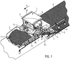
- figure 1 shows a road construction machine, which is designed in the form of a road finisher 1.
- the road finisher 1 is configured to produce a paving layer 3 from a paving material 2 in the direction of travel R.
- the road finisher 1 has a paving screed 4 , the paving width of which can be adjusted by means of pull-out parts 5 .
- Pull-out part 5 shown is an external control station 6 for an operator B provided.
- the operator B can set and monitor working functions of the screed 4 , in particular of the extension part 5 , at the outside control station 6 .
- the outside control station 6 is attached to a side shifter 7 .
- the side shifter 7 limits the width of the built-in layer 3.
- the road finisher 1 off figure 1 also has a driver's operating platform 8, which is located below a driver's overhead guard 9.
- a driver F of the road finisher 1 can control and monitor work processes running on the road finisher 1 on the driver operating platform 8 .
- figure 1 also shows that the driver F of the road finisher 1 is positioned on a driver's seat console 10, which is pivoted sideways out of the area of the driver's operating platform 8, so that the driver F can see processes running on the road finisher 1, in particular a fill level of the material stored in front of him within a material bunker 11 Installation material 2, can have a better overview.
- the paving material 2 is stored within the bunker 11 up to the side halves 12 of the bunker.
- the paving material 2 stored within the material bunker 11, in particular within the lateral halves 12 of the material bunker, is transported backwards to the screed 4 by means of a longitudinal conveyor device (not shown), counter to the direction of travel R of the road finisher 1, and is distributed in front of this within a transverse distribution channel 13 in the direction of the extension parts 5.
- the paving material 2 thus distributed transversely in front of the screed 4 and the extension parts 5 formed thereon is compacted to form the paving layer 3 while the paver 1 is paving.
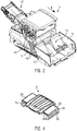
- FIG 2 shows a road construction machine, which is designed in the form of a feeder vehicle 14.
- the feeder vehicle 14 can during a material transfer process in the direction of travel R before the in figure 1 Road finisher 1 shown drive ahead and supply its material bunker 11 with paving material 2.
- This in figure 2 The feeder vehicle 14 shown has a material bunker 15 which comprises lateral material bunker halves 16 .
- the paving material 2 is transported from the material bunker 15 of the feeder vehicle 14 by means of a longitudinal conveyor against the direction of travel R to a feeder belt 17 and thrown by this into the material bunker 11 of the road finisher 1 driving closely behind.
- the feeder vehicle 14 shown has a driver operating platform 18, which is the same as in figure 1 shown driver operating platform 8 is structurally similar. Above all, the feeder vehicle 14 can figure 2 also have a swing-out driver's seat console 19 for a driver F.
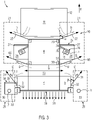
- FIG 3 shows a schematic representation of the road finisher 1 from the top view.
- the road finisher 1 has a first air barrier device 20, which generates an air wall 22 within an area 21 that is positioned to the side of the driver's operating platform 8, by means of which rising vapors and/or aerosols D , in particular those from the bunker halves 12, can be shielded by the driver F, who is positioned within the area 21, and transported away to the side.
- This air barrier principle is in figure 3 formed on both laterally adjacent zones of the driver's operating platform 8 .
- the first air barrier device 22 has a nozzle 24 positioned within an A-pillar 23 in order to generate the air wall 22 at an angle ⁇ to the direction of travel R.
- an air wall serving to protect the driver F positioned within area 21 could also be installed by means of a nozzle 27, which is arranged on a front edge 25 of an extendable roof segment 26, and/or by means of a nozzle 29, which is arranged on a substructure 28 the swing-out driver's seat console 10 is formed, are generated.
- On the other side of the paver 1 there could be a similar nozzle structure for creating the air wall 22 and/or another air wall lying within the area 21 .
- FIG. 3 a B-pillar 50 for the driver's overhead guard 9, which is positioned behind the A-pillar 23 in the direction of travel R.
- An air wall 60 is blown out of the B pillar 50 by means of a nozzle 51 installed therein, which forms an air duct K for the driver F together with the air wall 22 blown out of the A pillar 23 further forward.
- the driver F shown is positioned in a sealed position both against vapors and/or aerosols D rising in front of him from the material bunker area and against vapors and/or aerosols D rising behind him from the transverse distribution channel 13 .
- FIG. 12 further shows a second air barrier device 29, which is primarily assigned to a lateral area 30 of the external control station 6, in order to generate an air wall 31 blown out at an angle ⁇ to the direction of travel R in this zone.
- the air wall 31 protects an operator B of the external control station 6 positioned within the area 30 from vapors and/or aerosols D rising from the transverse distribution channel 13.
- figure 3 12 further shows that the second air barrier device 29 generates the air wall 31 by means of a nozzle 32 positioned on the side shifter 7 .
- a canopy 33 for the operator B is provided for the outside control station 6 on the left side of the screed.
- a nozzle 35 is formed along a front edge 34 to form a vertical air curtain directed in the direction of travel R in front of the operator B from top to bottom.
- figure 3 shows that the second air barrier device 29 is formed both on the left-hand and on the right-hand outside control station 6.
- a further nozzle 37 is formed along a rear wall 36 of the screed in order to produce an upwardly directed wall of air 45 essentially along the set screed width (see Figure 5B ) that rises as an air wall between the road finisher 1 and a following compactor vehicle.
- FIG. 3 shows figure 3 an air flow 38 which is blown out behind the paving screed 4 in the opposite direction to the travel direction R and covers the paving layer 3 produced in the form of an air carpet.
- figure 4 shows that in figure 1 driver's canopy 9 with extendable roof segments 26 that can be used for the road finisher 1.
- the driver's canopy 9 can also be used for the feeder vehicle 14 figure 2 be used.
- the roof segments 26 are positioned in the extended position.
- One of the two roof segments 26 is extended automatically, for example, in response to the driver's seat console 10, 19 positioned underneath pivoting out.
- figure 3 form an air wall for driver F.
- figure 4 that exits along an outer edge 39 of the roof segments 25 directed from top to bottom air flow.
- a driver F positioned underneath can thus be shielded within an air cabin from vapors and/or aerosols D rising from the goods bunker area.
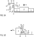
- Figure 5A shows a schematic representation of the screed 4 viewed from behind in the direction of travel R with the extension parts 5 and an external control station 6 arranged thereon with a canopy 33.
- An air flow 40 emerges from the canopy 33 from above through the nozzle 35 in front of the operator B positioned below.
- Figure 5A shows Figure 5A a vertically erected nozzle 41 for blowing out a sideways airflow 42 blowing away vapors and/or aerosols in front of the operator B sideways.
- Figure 5B shows in a schematic representation that a further nozzle 44 is arranged below a catwalk 43 fastened to the rear wall 36 of the screed.
- the nozzle 44 is designed to below the catwalk 43 to generate an air flow 38 directed counter to the direction of travel R directly above the built-in layer 3 in order to cover vapors and/or aerosols D rising from the built-in layer 3 .
- the first and/or second air barrier device 20, 29 shown in the figures can be figures 1 and 2 shown engine compartment opening 46, 46 'directly above the chassis of the road finisher 1 or the loading vehicle 14 draw air.
Landscapes
- Engineering & Computer Science (AREA)
- Architecture (AREA)
- Civil Engineering (AREA)
- Structural Engineering (AREA)
- Road Paving Machines (AREA)
Priority Applications (7)
| Application Number | Priority Date | Filing Date | Title |
|---|---|---|---|
| PL21174880.1T PL4092191T3 (pl) | 2021-05-20 | 2021-05-20 | Maszyno do budowy dróg z urządzeniem bariery powietrznej oraz sposób |
| EP21174880.1A EP4092191B1 (fr) | 2021-05-20 | 2021-05-20 | Engin de construction routière pourvu de dispositif à barrière d'air et procédé |
| BR102022009241-9A BR102022009241A2 (pt) | 2021-05-20 | 2022-05-12 | Máquina de construção de estrada e método para gerar um fluxo de ar durante a operação da mesma |
| CN202210563226.7A CN115387181B (zh) | 2021-05-20 | 2022-05-19 | 具有空气屏障装置的道路施工机械及方法 |
| CN202221222847.0U CN218090392U (zh) | 2021-05-20 | 2022-05-19 | 道路施工机械 |
| JP2022082533A JP2022179443A (ja) | 2021-05-20 | 2022-05-19 | エアーバリア装置を有する道路建設機械及び方法 |
| US17/749,967 US12134865B2 (en) | 2021-05-20 | 2022-05-20 | Road construction machine with air barrier device and method |
Applications Claiming Priority (1)
| Application Number | Priority Date | Filing Date | Title |
|---|---|---|---|
| EP21174880.1A EP4092191B1 (fr) | 2021-05-20 | 2021-05-20 | Engin de construction routière pourvu de dispositif à barrière d'air et procédé |
Publications (2)
| Publication Number | Publication Date |
|---|---|
| EP4092191A1 true EP4092191A1 (fr) | 2022-11-23 |
| EP4092191B1 EP4092191B1 (fr) | 2024-02-28 |
Family
ID=76034473
Family Applications (1)
| Application Number | Title | Priority Date | Filing Date |
|---|---|---|---|
| EP21174880.1A Active EP4092191B1 (fr) | 2021-05-20 | 2021-05-20 | Engin de construction routière pourvu de dispositif à barrière d'air et procédé |
Country Status (6)
| Country | Link |
|---|---|
| US (1) | US12134865B2 (fr) |
| EP (1) | EP4092191B1 (fr) |
| JP (1) | JP2022179443A (fr) |
| CN (2) | CN115387181B (fr) |
| BR (1) | BR102022009241A2 (fr) |
| PL (1) | PL4092191T3 (fr) |
Cited By (2)
| Publication number | Priority date | Publication date | Assignee | Title |
|---|---|---|---|---|
| EP4438810A1 (fr) * | 2023-03-27 | 2024-10-02 | Joseph Vögele AG | Engin de construction de routes avec console de siège pour l'alimentation en air frais et procédé |
| EP4438811A1 (fr) * | 2023-03-27 | 2024-10-02 | Joseph Vögele AG | Finisseuse de route ou véhicule chargeur comprenant un système d'air frais |
Families Citing this family (2)
| Publication number | Priority date | Publication date | Assignee | Title |
|---|---|---|---|---|
| PL4092191T3 (pl) * | 2021-05-20 | 2024-07-15 | Joseph Vögele AG | Maszyno do budowy dróg z urządzeniem bariery powietrznej oraz sposób |
| EP4159923B1 (fr) * | 2021-09-30 | 2024-06-05 | Joseph Vögele AG | Finisseuse routière pourvue de nébuliseur |
Citations (10)
| Publication number | Priority date | Publication date | Assignee | Title |
|---|---|---|---|---|
| EP0843044A1 (fr) | 1996-11-19 | 1998-05-20 | Joseph Vögele AG | Finisseur automobile |
| DE202004004748U1 (de) * | 2004-03-23 | 2004-06-03 | Sonnen, Klaus | Straßendeckenfertiger |
| DE202012002966U1 (de) * | 2012-03-06 | 2012-04-10 | Abg Allgemeine Baumaschinen-Gesellschaft Mbh | Straßenfertiger |
| DE102012007869A1 (de) | 2012-03-22 | 2013-09-26 | Dynapac Gmbh | Straßenfertiger |
| WO2013185867A1 (fr) | 2012-06-12 | 2013-12-19 | Abg Allgemeine Baumaschinen-Gesellschaft Mbh | Finisseur |
| JP2014139388A (ja) | 2013-01-21 | 2014-07-31 | Sumitomo (Shi) Construction Machinery Co Ltd | アスファルト舗装機械 |
| JP2014139389A (ja) | 2013-01-21 | 2014-07-31 | Sumitomo (Shi) Construction Machinery Co Ltd | アスファルト舗装機械 |
| JP2015101898A (ja) * | 2013-11-26 | 2015-06-04 | 住友建機株式会社 | アスファルト舗装機械 |
| DE202018104562U1 (de) * | 2018-08-08 | 2019-11-12 | Joseph Vögele AG | Straßenfertiger oder Beschickerfahrzeug mit Tank |
| DE102020123723A1 (de) | 2019-09-11 | 2021-03-11 | Dynapac Gmbh | Straßenfertiger |
Family Cites Families (12)
| Publication number | Priority date | Publication date | Assignee | Title |
|---|---|---|---|---|
| US6302066B1 (en) * | 1999-04-30 | 2001-10-16 | Caterpillar Inc. | Apparatus and method of cooling a work machine |
| US8033899B2 (en) * | 2005-08-31 | 2011-10-11 | Kubota Corporation | Cabin for a work vehicle |
| ATE457388T1 (de) * | 2006-08-01 | 2010-02-15 | Kuepper Weisser Gmbh | Winterdienst-streufahrzeug |
| PL2514872T3 (pl) * | 2011-04-18 | 2015-12-31 | Joseph Voegele Ag | Wykańczarka do wbudowywania nawierzchni drogowej |
| DE202012003669U1 (de) * | 2012-04-12 | 2013-07-15 | Joseph Vögele AG | Fahrerdach für Bedienstand einer Straßenbaumaschine |
| JP2014012933A (ja) * | 2012-07-03 | 2014-01-23 | Sumitomo (Shi) Construction Machinery Co Ltd | アスファルト舗装機械 |
| PL2821551T3 (pl) * | 2013-07-05 | 2016-08-31 | Joseph Voegele Ag | Maszyna budowlana z ogrzewalnymi strukturami łożyskowymi |
| JP6787267B2 (ja) * | 2017-07-20 | 2020-11-18 | 株式会社デンソー | ブロワシステム |
| US20200079175A1 (en) * | 2018-09-06 | 2020-03-12 | Cnh Industrial America Llc | Cab with fresh air path through the posts |
| JP7161184B2 (ja) * | 2018-10-04 | 2022-10-26 | 株式会社トルネックス | 清浄空気供給装置 |
| CN212022818U (zh) * | 2020-04-20 | 2020-11-27 | 唐山大成路桥有限公司 | 一种带有驾驶员防护装置的沥青路面摊铺机 |
| PL4092191T3 (pl) * | 2021-05-20 | 2024-07-15 | Joseph Vögele AG | Maszyno do budowy dróg z urządzeniem bariery powietrznej oraz sposób |
-
2021
- 2021-05-20 PL PL21174880.1T patent/PL4092191T3/pl unknown
- 2021-05-20 EP EP21174880.1A patent/EP4092191B1/fr active Active
-
2022
- 2022-05-12 BR BR102022009241-9A patent/BR102022009241A2/pt unknown
- 2022-05-19 CN CN202210563226.7A patent/CN115387181B/zh active Active
- 2022-05-19 CN CN202221222847.0U patent/CN218090392U/zh active Active
- 2022-05-19 JP JP2022082533A patent/JP2022179443A/ja active Pending
- 2022-05-20 US US17/749,967 patent/US12134865B2/en active Active
Patent Citations (10)
| Publication number | Priority date | Publication date | Assignee | Title |
|---|---|---|---|---|
| EP0843044A1 (fr) | 1996-11-19 | 1998-05-20 | Joseph Vögele AG | Finisseur automobile |
| DE202004004748U1 (de) * | 2004-03-23 | 2004-06-03 | Sonnen, Klaus | Straßendeckenfertiger |
| DE202012002966U1 (de) * | 2012-03-06 | 2012-04-10 | Abg Allgemeine Baumaschinen-Gesellschaft Mbh | Straßenfertiger |
| DE102012007869A1 (de) | 2012-03-22 | 2013-09-26 | Dynapac Gmbh | Straßenfertiger |
| WO2013185867A1 (fr) | 2012-06-12 | 2013-12-19 | Abg Allgemeine Baumaschinen-Gesellschaft Mbh | Finisseur |
| JP2014139388A (ja) | 2013-01-21 | 2014-07-31 | Sumitomo (Shi) Construction Machinery Co Ltd | アスファルト舗装機械 |
| JP2014139389A (ja) | 2013-01-21 | 2014-07-31 | Sumitomo (Shi) Construction Machinery Co Ltd | アスファルト舗装機械 |
| JP2015101898A (ja) * | 2013-11-26 | 2015-06-04 | 住友建機株式会社 | アスファルト舗装機械 |
| DE202018104562U1 (de) * | 2018-08-08 | 2019-11-12 | Joseph Vögele AG | Straßenfertiger oder Beschickerfahrzeug mit Tank |
| DE102020123723A1 (de) | 2019-09-11 | 2021-03-11 | Dynapac Gmbh | Straßenfertiger |
Cited By (2)
| Publication number | Priority date | Publication date | Assignee | Title |
|---|---|---|---|---|
| EP4438810A1 (fr) * | 2023-03-27 | 2024-10-02 | Joseph Vögele AG | Engin de construction de routes avec console de siège pour l'alimentation en air frais et procédé |
| EP4438811A1 (fr) * | 2023-03-27 | 2024-10-02 | Joseph Vögele AG | Finisseuse de route ou véhicule chargeur comprenant un système d'air frais |
Also Published As
| Publication number | Publication date |
|---|---|
| US20220372715A1 (en) | 2022-11-24 |
| PL4092191T3 (pl) | 2024-07-15 |
| BR102022009241A2 (pt) | 2023-01-03 |
| CN115387181B (zh) | 2026-01-30 |
| CN218090392U (zh) | 2022-12-20 |
| EP4092191B1 (fr) | 2024-02-28 |
| JP2022179443A (ja) | 2022-12-02 |
| US12134865B2 (en) | 2024-11-05 |
| CN115387181A (zh) | 2022-11-25 |
Similar Documents
| Publication | Publication Date | Title |
|---|---|---|
| EP4092191B1 (fr) | Engin de construction routière pourvu de dispositif à barrière d'air et procédé | |
| EP1507925B1 (fr) | Unite et procede d'aspiration pour eliminer la poussiere sur des fraiseuses | |
| EP4056759B1 (fr) | Finisseuse de route pourvu de dispositif d'aspiration | |
| EP0255004B1 (fr) | Aménagement pour l'aération d'un véhicule à moteur | |
| EP2038154B1 (fr) | Véhicule ferroviaire équipé d'un système de refroidissement pour des composants placés dans une zone sous plancher | |
| EP2880220B1 (fr) | Finisseur | |
| EP2921327B1 (fr) | Cabine de conducteur d'une machine-outil à usage agricole ou dans les travaux publics | |
| EP2835471B2 (fr) | Fraiseuse routière et procédé de fraisage et de transport du flux de matériau fraisé | |
| DE102015110896B4 (de) | Geräuschdämmender Schnorchelkanal für Umluftöffnung einer Fahrzeuglüftungsanlage | |
| DE102020123723A1 (de) | Straßenfertiger | |
| EP1325824A2 (fr) | Dispositif de ventilation pour un toit de véhicule | |
| EP4438810B1 (fr) | Engin de construction de routes avec console de siège pour l'alimentation en air frais et procédé | |
| DE102021118686A1 (de) | Bodenfräsmaschine und verfahren zum absaugen und ausblasen staubbelasteter luft bei einer bodenfräsmaschine | |
| EP3075622B1 (fr) | Véhicule équipé d'une gaine d'aération débouchant à la surface du véhicule | |
| EP4306717B1 (fr) | Finisseuse de routes | |
| DE2724019A1 (de) | Heizungs- und/oder belueftungseinrichtung fuer ein kraftfahrzeug | |
| DE102005006250B3 (de) | Fahrzeugkarosserie eines Kraftwagens | |
| EP2642027A1 (fr) | Finisseuse | |
| EP0843044A1 (fr) | Finisseur automobile | |
| EP4306716B1 (fr) | Machine de construction routière avec dispositif de soufflage | |
| EP3040149B1 (fr) | Dispositif de soudure avec distribution de gaz | |
| EP4438811A1 (fr) | Finisseuse de route ou véhicule chargeur comprenant un système d'air frais | |
| DE9113985U1 (de) | Selbstfahrende Saugkehrmaschine | |
| DE102016222150B4 (de) | Anordnung und Verfahren zur Zuführung von Belüftungsluft zu einer Belüftungseinrichtung für einen Fahrzeuginnenraum sowie Kraftfahrzeug | |
| DE29907779U1 (de) | Vorrichtung zum Fernhalten von in einem Lackierraum erzeugten Lack-Overspray von einem Overspray-geschützten Raum |
Legal Events
| Date | Code | Title | Description |
|---|---|---|---|
| PUAI | Public reference made under article 153(3) epc to a published international application that has entered the european phase |
Free format text: ORIGINAL CODE: 0009012 |
|
| STAA | Information on the status of an ep patent application or granted ep patent |
Free format text: STATUS: THE APPLICATION HAS BEEN PUBLISHED |
|
| AK | Designated contracting states |
Kind code of ref document: A1 Designated state(s): AL AT BE BG CH CY CZ DE DK EE ES FI FR GB GR HR HU IE IS IT LI LT LU LV MC MK MT NL NO PL PT RO RS SE SI SK SM TR |
|
| STAA | Information on the status of an ep patent application or granted ep patent |
Free format text: STATUS: REQUEST FOR EXAMINATION WAS MADE |
|
| 17P | Request for examination filed |
Effective date: 20230523 |
|
| P01 | Opt-out of the competence of the unified patent court (upc) registered |
Effective date: 20230524 |
|
| RBV | Designated contracting states (corrected) |
Designated state(s): AL AT BE BG CH CY CZ DE DK EE ES FI FR GB GR HR HU IE IS IT LI LT LU LV MC MK MT NL NO PL PT RO RS SE SI SK SM TR |
|
| GRAP | Despatch of communication of intention to grant a patent |
Free format text: ORIGINAL CODE: EPIDOSNIGR1 |
|
| STAA | Information on the status of an ep patent application or granted ep patent |
Free format text: STATUS: GRANT OF PATENT IS INTENDED |
|
| INTG | Intention to grant announced |
Effective date: 20230925 |
|
| RIN1 | Information on inventor provided before grant (corrected) |
Inventor name: ERDTMANN, BERNHARD Inventor name: WEBER, STEFAN Inventor name: PONTIUS, JOHANNES Inventor name: KESSLER, HELMUT Inventor name: GRIMM, FRANK Inventor name: SEITHER, THOMAS Inventor name: THEOBALD, MAXIMILIAN Inventor name: HERZBERG, INGO Inventor name: DRAXLER, DANIEL Inventor name: BOELLERT, TOBIAS Inventor name: FLEISCHER, BASTIAN Inventor name: OETTINGER, KLAUS |
|
| GRAS | Grant fee paid |
Free format text: ORIGINAL CODE: EPIDOSNIGR3 |
|
| GRAA | (expected) grant |
Free format text: ORIGINAL CODE: 0009210 |
|
| STAA | Information on the status of an ep patent application or granted ep patent |
Free format text: STATUS: THE PATENT HAS BEEN GRANTED |
|
| AK | Designated contracting states |
Kind code of ref document: B1 Designated state(s): AL AT BE BG CH CY CZ DE DK EE ES FI FR GB GR HR HU IE IS IT LI LT LU LV MC MK MT NL NO PL PT RO RS SE SI SK SM TR |
|
| REG | Reference to a national code |
Ref country code: GB Ref legal event code: FG4D Free format text: NOT ENGLISH |
|
| REG | Reference to a national code |
Ref country code: CH Ref legal event code: EP |
|
| REG | Reference to a national code |
Ref country code: DE Ref legal event code: R096 Ref document number: 502021002803 Country of ref document: DE |
|
| REG | Reference to a national code |
Ref country code: IE Ref legal event code: FG4D Free format text: LANGUAGE OF EP DOCUMENT: GERMAN |
|
| REG | Reference to a national code |
Ref country code: LT Ref legal event code: MG9D |
|
| PG25 | Lapsed in a contracting state [announced via postgrant information from national office to epo] |
Ref country code: IS Free format text: LAPSE BECAUSE OF FAILURE TO SUBMIT A TRANSLATION OF THE DESCRIPTION OR TO PAY THE FEE WITHIN THE PRESCRIBED TIME-LIMIT Effective date: 20240628 |
|
| REG | Reference to a national code |
Ref country code: NL Ref legal event code: MP Effective date: 20240228 |
|
| PG25 | Lapsed in a contracting state [announced via postgrant information from national office to epo] |
Ref country code: LT Free format text: LAPSE BECAUSE OF FAILURE TO SUBMIT A TRANSLATION OF THE DESCRIPTION OR TO PAY THE FEE WITHIN THE PRESCRIBED TIME-LIMIT Effective date: 20240228 |
|
| PG25 | Lapsed in a contracting state [announced via postgrant information from national office to epo] |
Ref country code: GR Free format text: LAPSE BECAUSE OF FAILURE TO SUBMIT A TRANSLATION OF THE DESCRIPTION OR TO PAY THE FEE WITHIN THE PRESCRIBED TIME-LIMIT Effective date: 20240529 |
|
| PG25 | Lapsed in a contracting state [announced via postgrant information from national office to epo] |
Ref country code: RS Free format text: LAPSE BECAUSE OF FAILURE TO SUBMIT A TRANSLATION OF THE DESCRIPTION OR TO PAY THE FEE WITHIN THE PRESCRIBED TIME-LIMIT Effective date: 20240528 Ref country code: NL Free format text: LAPSE BECAUSE OF FAILURE TO SUBMIT A TRANSLATION OF THE DESCRIPTION OR TO PAY THE FEE WITHIN THE PRESCRIBED TIME-LIMIT Effective date: 20240228 Ref country code: HR Free format text: LAPSE BECAUSE OF FAILURE TO SUBMIT A TRANSLATION OF THE DESCRIPTION OR TO PAY THE FEE WITHIN THE PRESCRIBED TIME-LIMIT Effective date: 20240228 |
|
| PG25 | Lapsed in a contracting state [announced via postgrant information from national office to epo] |
Ref country code: ES Free format text: LAPSE BECAUSE OF FAILURE TO SUBMIT A TRANSLATION OF THE DESCRIPTION OR TO PAY THE FEE WITHIN THE PRESCRIBED TIME-LIMIT Effective date: 20240228 |
|
| PG25 | Lapsed in a contracting state [announced via postgrant information from national office to epo] |
Ref country code: RS Free format text: LAPSE BECAUSE OF FAILURE TO SUBMIT A TRANSLATION OF THE DESCRIPTION OR TO PAY THE FEE WITHIN THE PRESCRIBED TIME-LIMIT Effective date: 20240528 Ref country code: NO Free format text: LAPSE BECAUSE OF FAILURE TO SUBMIT A TRANSLATION OF THE DESCRIPTION OR TO PAY THE FEE WITHIN THE PRESCRIBED TIME-LIMIT Effective date: 20240528 Ref country code: NL Free format text: LAPSE BECAUSE OF FAILURE TO SUBMIT A TRANSLATION OF THE DESCRIPTION OR TO PAY THE FEE WITHIN THE PRESCRIBED TIME-LIMIT Effective date: 20240228 Ref country code: LT Free format text: LAPSE BECAUSE OF FAILURE TO SUBMIT A TRANSLATION OF THE DESCRIPTION OR TO PAY THE FEE WITHIN THE PRESCRIBED TIME-LIMIT Effective date: 20240228 Ref country code: IS Free format text: LAPSE BECAUSE OF FAILURE TO SUBMIT A TRANSLATION OF THE DESCRIPTION OR TO PAY THE FEE WITHIN THE PRESCRIBED TIME-LIMIT Effective date: 20240628 Ref country code: HR Free format text: LAPSE BECAUSE OF FAILURE TO SUBMIT A TRANSLATION OF THE DESCRIPTION OR TO PAY THE FEE WITHIN THE PRESCRIBED TIME-LIMIT Effective date: 20240228 Ref country code: GR Free format text: LAPSE BECAUSE OF FAILURE TO SUBMIT A TRANSLATION OF THE DESCRIPTION OR TO PAY THE FEE WITHIN THE PRESCRIBED TIME-LIMIT Effective date: 20240529 Ref country code: FI Free format text: LAPSE BECAUSE OF FAILURE TO SUBMIT A TRANSLATION OF THE DESCRIPTION OR TO PAY THE FEE WITHIN THE PRESCRIBED TIME-LIMIT Effective date: 20240228 Ref country code: ES Free format text: LAPSE BECAUSE OF FAILURE TO SUBMIT A TRANSLATION OF THE DESCRIPTION OR TO PAY THE FEE WITHIN THE PRESCRIBED TIME-LIMIT Effective date: 20240228 Ref country code: BG Free format text: LAPSE BECAUSE OF FAILURE TO SUBMIT A TRANSLATION OF THE DESCRIPTION OR TO PAY THE FEE WITHIN THE PRESCRIBED TIME-LIMIT Effective date: 20240228 |
|
| PG25 | Lapsed in a contracting state [announced via postgrant information from national office to epo] |
Ref country code: PT Free format text: LAPSE BECAUSE OF FAILURE TO SUBMIT A TRANSLATION OF THE DESCRIPTION OR TO PAY THE FEE WITHIN THE PRESCRIBED TIME-LIMIT Effective date: 20240628 |
|
| PG25 | Lapsed in a contracting state [announced via postgrant information from national office to epo] |
Ref country code: SE Free format text: LAPSE BECAUSE OF FAILURE TO SUBMIT A TRANSLATION OF THE DESCRIPTION OR TO PAY THE FEE WITHIN THE PRESCRIBED TIME-LIMIT Effective date: 20240228 Ref country code: PT Free format text: LAPSE BECAUSE OF FAILURE TO SUBMIT A TRANSLATION OF THE DESCRIPTION OR TO PAY THE FEE WITHIN THE PRESCRIBED TIME-LIMIT Effective date: 20240628 Ref country code: LV Free format text: LAPSE BECAUSE OF FAILURE TO SUBMIT A TRANSLATION OF THE DESCRIPTION OR TO PAY THE FEE WITHIN THE PRESCRIBED TIME-LIMIT Effective date: 20240228 |
|
| PG25 | Lapsed in a contracting state [announced via postgrant information from national office to epo] |
Ref country code: DK Free format text: LAPSE BECAUSE OF FAILURE TO SUBMIT A TRANSLATION OF THE DESCRIPTION OR TO PAY THE FEE WITHIN THE PRESCRIBED TIME-LIMIT Effective date: 20240228 |
|
| PG25 | Lapsed in a contracting state [announced via postgrant information from national office to epo] |
Ref country code: SM Free format text: LAPSE BECAUSE OF FAILURE TO SUBMIT A TRANSLATION OF THE DESCRIPTION OR TO PAY THE FEE WITHIN THE PRESCRIBED TIME-LIMIT Effective date: 20240228 |
|
| PG25 | Lapsed in a contracting state [announced via postgrant information from national office to epo] |
Ref country code: EE Free format text: LAPSE BECAUSE OF FAILURE TO SUBMIT A TRANSLATION OF THE DESCRIPTION OR TO PAY THE FEE WITHIN THE PRESCRIBED TIME-LIMIT Effective date: 20240228 Ref country code: CZ Free format text: LAPSE BECAUSE OF FAILURE TO SUBMIT A TRANSLATION OF THE DESCRIPTION OR TO PAY THE FEE WITHIN THE PRESCRIBED TIME-LIMIT Effective date: 20240228 |
|
| PG25 | Lapsed in a contracting state [announced via postgrant information from national office to epo] |
Ref country code: SK Free format text: LAPSE BECAUSE OF FAILURE TO SUBMIT A TRANSLATION OF THE DESCRIPTION OR TO PAY THE FEE WITHIN THE PRESCRIBED TIME-LIMIT Effective date: 20240228 |
|
| PG25 | Lapsed in a contracting state [announced via postgrant information from national office to epo] |
Ref country code: SM Free format text: LAPSE BECAUSE OF FAILURE TO SUBMIT A TRANSLATION OF THE DESCRIPTION OR TO PAY THE FEE WITHIN THE PRESCRIBED TIME-LIMIT Effective date: 20240228 Ref country code: SK Free format text: LAPSE BECAUSE OF FAILURE TO SUBMIT A TRANSLATION OF THE DESCRIPTION OR TO PAY THE FEE WITHIN THE PRESCRIBED TIME-LIMIT Effective date: 20240228 Ref country code: RO Free format text: LAPSE BECAUSE OF FAILURE TO SUBMIT A TRANSLATION OF THE DESCRIPTION OR TO PAY THE FEE WITHIN THE PRESCRIBED TIME-LIMIT Effective date: 20240228 Ref country code: EE Free format text: LAPSE BECAUSE OF FAILURE TO SUBMIT A TRANSLATION OF THE DESCRIPTION OR TO PAY THE FEE WITHIN THE PRESCRIBED TIME-LIMIT Effective date: 20240228 Ref country code: DK Free format text: LAPSE BECAUSE OF FAILURE TO SUBMIT A TRANSLATION OF THE DESCRIPTION OR TO PAY THE FEE WITHIN THE PRESCRIBED TIME-LIMIT Effective date: 20240228 Ref country code: CZ Free format text: LAPSE BECAUSE OF FAILURE TO SUBMIT A TRANSLATION OF THE DESCRIPTION OR TO PAY THE FEE WITHIN THE PRESCRIBED TIME-LIMIT Effective date: 20240228 |
|
| REG | Reference to a national code |
Ref country code: DE Ref legal event code: R026 Ref document number: 502021002803 Country of ref document: DE |
|
| PLBI | Opposition filed |
Free format text: ORIGINAL CODE: 0009260 |
|
| REG | Reference to a national code |
Ref country code: CH Ref legal event code: PL |
|
| 26 | Opposition filed |
Opponent name: DYNAPAC GMBH Effective date: 20241122 |
|
| PG25 | Lapsed in a contracting state [announced via postgrant information from national office to epo] |
Ref country code: MC Free format text: LAPSE BECAUSE OF FAILURE TO SUBMIT A TRANSLATION OF THE DESCRIPTION OR TO PAY THE FEE WITHIN THE PRESCRIBED TIME-LIMIT Effective date: 20240228 |
|
| PG25 | Lapsed in a contracting state [announced via postgrant information from national office to epo] |
Ref country code: LU Free format text: LAPSE BECAUSE OF NON-PAYMENT OF DUE FEES Effective date: 20240520 |
|
| PG25 | Lapsed in a contracting state [announced via postgrant information from national office to epo] |
Ref country code: MC Free format text: LAPSE BECAUSE OF FAILURE TO SUBMIT A TRANSLATION OF THE DESCRIPTION OR TO PAY THE FEE WITHIN THE PRESCRIBED TIME-LIMIT Effective date: 20240228 Ref country code: LU Free format text: LAPSE BECAUSE OF NON-PAYMENT OF DUE FEES Effective date: 20240520 Ref country code: CH Free format text: LAPSE BECAUSE OF NON-PAYMENT OF DUE FEES Effective date: 20240531 |
|
| PLAX | Notice of opposition and request to file observation + time limit sent |
Free format text: ORIGINAL CODE: EPIDOSNOBS2 |
|
| REG | Reference to a national code |
Ref country code: BE Ref legal event code: MM Effective date: 20240531 |
|
| PG25 | Lapsed in a contracting state [announced via postgrant information from national office to epo] |
Ref country code: IE Free format text: LAPSE BECAUSE OF NON-PAYMENT OF DUE FEES Effective date: 20240520 |
|
| PG25 | Lapsed in a contracting state [announced via postgrant information from national office to epo] |
Ref country code: SI Free format text: LAPSE BECAUSE OF FAILURE TO SUBMIT A TRANSLATION OF THE DESCRIPTION OR TO PAY THE FEE WITHIN THE PRESCRIBED TIME-LIMIT Effective date: 20240228 Ref country code: BE Free format text: LAPSE BECAUSE OF NON-PAYMENT OF DUE FEES Effective date: 20240531 |
|
| PLBB | Reply of patent proprietor to notice(s) of opposition received |
Free format text: ORIGINAL CODE: EPIDOSNOBS3 |
|
| PGFP | Annual fee paid to national office [announced via postgrant information from national office to epo] |
Ref country code: PL Payment date: 20250507 Year of fee payment: 5 Ref country code: DE Payment date: 20250528 Year of fee payment: 5 |
|
| PGFP | Annual fee paid to national office [announced via postgrant information from national office to epo] |
Ref country code: GB Payment date: 20250524 Year of fee payment: 5 |
|
| PGFP | Annual fee paid to national office [announced via postgrant information from national office to epo] |
Ref country code: IT Payment date: 20250529 Year of fee payment: 5 |
|
| PGFP | Annual fee paid to national office [announced via postgrant information from national office to epo] |
Ref country code: FR Payment date: 20250520 Year of fee payment: 5 |
|
| PGFP | Annual fee paid to national office [announced via postgrant information from national office to epo] |
Ref country code: AT Payment date: 20250721 Year of fee payment: 5 |
|
| PG25 | Lapsed in a contracting state [announced via postgrant information from national office to epo] |
Ref country code: CY Free format text: LAPSE BECAUSE OF FAILURE TO SUBMIT A TRANSLATION OF THE DESCRIPTION OR TO PAY THE FEE WITHIN THE PRESCRIBED TIME-LIMIT; INVALID AB INITIO Effective date: 20210520 |
|
| PG25 | Lapsed in a contracting state [announced via postgrant information from national office to epo] |
Ref country code: HU Free format text: LAPSE BECAUSE OF FAILURE TO SUBMIT A TRANSLATION OF THE DESCRIPTION OR TO PAY THE FEE WITHIN THE PRESCRIBED TIME-LIMIT; INVALID AB INITIO Effective date: 20210520 |