EP2835531A2 - Machine à piston axial hydrostatique dans une construction à axe oblique - Google Patents
Machine à piston axial hydrostatique dans une construction à axe oblique Download PDFInfo
- Publication number
- EP2835531A2 EP2835531A2 EP20140179555 EP14179555A EP2835531A2 EP 2835531 A2 EP2835531 A2 EP 2835531A2 EP 20140179555 EP20140179555 EP 20140179555 EP 14179555 A EP14179555 A EP 14179555A EP 2835531 A2 EP2835531 A2 EP 2835531A2
- Authority
- EP
- European Patent Office
- Prior art keywords
- drive shaft
- cylinder drum
- axial piston
- piston machine
- rotation
- Prior art date
- Legal status (The legal status is an assumption and is not a legal conclusion. Google has not performed a legal analysis and makes no representation as to the accuracy of the status listed.)
- Withdrawn
Links
Images


Classifications
-
- F—MECHANICAL ENGINEERING; LIGHTING; HEATING; WEAPONS; BLASTING
- F04—POSITIVE - DISPLACEMENT MACHINES FOR LIQUIDS; PUMPS FOR LIQUIDS OR ELASTIC FLUIDS
- F04B—POSITIVE-DISPLACEMENT MACHINES FOR LIQUIDS; PUMPS
- F04B1/00—Multi-cylinder machines or pumps characterised by number or arrangement of cylinders
- F04B1/12—Multi-cylinder machines or pumps characterised by number or arrangement of cylinders having cylinder axes coaxial with, or parallel or inclined to, main shaft axis
- F04B1/20—Multi-cylinder machines or pumps characterised by number or arrangement of cylinders having cylinder axes coaxial with, or parallel or inclined to, main shaft axis having rotary cylinder block
-
- F—MECHANICAL ENGINEERING; LIGHTING; HEATING; WEAPONS; BLASTING
- F01—MACHINES OR ENGINES IN GENERAL; ENGINE PLANTS IN GENERAL; STEAM ENGINES
- F01B—MACHINES OR ENGINES, IN GENERAL OR OF POSITIVE-DISPLACEMENT TYPE, e.g. STEAM ENGINES
- F01B3/00—Reciprocating-piston machines or engines with cylinder axes coaxial with, or parallel or inclined to, main shaft axis
- F01B3/0082—Details
- F01B3/0085—Pistons
-
- F—MECHANICAL ENGINEERING; LIGHTING; HEATING; WEAPONS; BLASTING
- F04—POSITIVE - DISPLACEMENT MACHINES FOR LIQUIDS; PUMPS FOR LIQUIDS OR ELASTIC FLUIDS
- F04B—POSITIVE-DISPLACEMENT MACHINES FOR LIQUIDS; PUMPS
- F04B1/00—Multi-cylinder machines or pumps characterised by number or arrangement of cylinders
- F04B1/12—Multi-cylinder machines or pumps characterised by number or arrangement of cylinders having cylinder axes coaxial with, or parallel or inclined to, main shaft axis
- F04B1/20—Multi-cylinder machines or pumps characterised by number or arrangement of cylinders having cylinder axes coaxial with, or parallel or inclined to, main shaft axis having rotary cylinder block
- F04B1/2092—Means for connecting rotating cylinder barrels and rotating inclined swash plates
-
- F—MECHANICAL ENGINEERING; LIGHTING; HEATING; WEAPONS; BLASTING
- F01—MACHINES OR ENGINES IN GENERAL; ENGINE PLANTS IN GENERAL; STEAM ENGINES
- F01B—MACHINES OR ENGINES, IN GENERAL OR OF POSITIVE-DISPLACEMENT TYPE, e.g. STEAM ENGINES
- F01B3/00—Reciprocating-piston machines or engines with cylinder axes coaxial with, or parallel or inclined to, main shaft axis
- F01B3/02—Reciprocating-piston machines or engines with cylinder axes coaxial with, or parallel or inclined to, main shaft axis with wobble-plate
-
- F—MECHANICAL ENGINEERING; LIGHTING; HEATING; WEAPONS; BLASTING
- F03—MACHINES OR ENGINES FOR LIQUIDS; WIND, SPRING, OR WEIGHT MOTORS; PRODUCING MECHANICAL POWER OR A REACTIVE PROPULSIVE THRUST, NOT OTHERWISE PROVIDED FOR
- F03C—POSITIVE-DISPLACEMENT ENGINES DRIVEN BY LIQUIDS
- F03C1/00—Reciprocating-piston liquid engines
- F03C1/02—Reciprocating-piston liquid engines with multiple-cylinders, characterised by the number or arrangement of cylinders
- F03C1/06—Reciprocating-piston liquid engines with multiple-cylinders, characterised by the number or arrangement of cylinders with cylinder axes generally coaxial with, or parallel or inclined to, main shaft axis
- F03C1/0602—Component parts, details
- F03C1/0607—Driven means
-
- F—MECHANICAL ENGINEERING; LIGHTING; HEATING; WEAPONS; BLASTING
- F03—MACHINES OR ENGINES FOR LIQUIDS; WIND, SPRING, OR WEIGHT MOTORS; PRODUCING MECHANICAL POWER OR A REACTIVE PROPULSIVE THRUST, NOT OTHERWISE PROVIDED FOR
- F03C—POSITIVE-DISPLACEMENT ENGINES DRIVEN BY LIQUIDS
- F03C1/00—Reciprocating-piston liquid engines
- F03C1/02—Reciprocating-piston liquid engines with multiple-cylinders, characterised by the number or arrangement of cylinders
- F03C1/06—Reciprocating-piston liquid engines with multiple-cylinders, characterised by the number or arrangement of cylinders with cylinder axes generally coaxial with, or parallel or inclined to, main shaft axis
- F03C1/0636—Reciprocating-piston liquid engines with multiple-cylinders, characterised by the number or arrangement of cylinders with cylinder axes generally coaxial with, or parallel or inclined to, main shaft axis having rotary cylinder block
- F03C1/0644—Component parts
- F03C1/0668—Swash or actuated plate
- F03C1/0671—Swash or actuated plate bearing means or driven axis bearing means
-
- F—MECHANICAL ENGINEERING; LIGHTING; HEATING; WEAPONS; BLASTING
- F03—MACHINES OR ENGINES FOR LIQUIDS; WIND, SPRING, OR WEIGHT MOTORS; PRODUCING MECHANICAL POWER OR A REACTIVE PROPULSIVE THRUST, NOT OTHERWISE PROVIDED FOR
- F03C—POSITIVE-DISPLACEMENT ENGINES DRIVEN BY LIQUIDS
- F03C1/00—Reciprocating-piston liquid engines
- F03C1/02—Reciprocating-piston liquid engines with multiple-cylinders, characterised by the number or arrangement of cylinders
- F03C1/06—Reciprocating-piston liquid engines with multiple-cylinders, characterised by the number or arrangement of cylinders with cylinder axes generally coaxial with, or parallel or inclined to, main shaft axis
- F03C1/0636—Reciprocating-piston liquid engines with multiple-cylinders, characterised by the number or arrangement of cylinders with cylinder axes generally coaxial with, or parallel or inclined to, main shaft axis having rotary cylinder block
- F03C1/0673—Connection between rotating cylinder and rotating inclined swash plate
-
- F—MECHANICAL ENGINEERING; LIGHTING; HEATING; WEAPONS; BLASTING
- F04—POSITIVE - DISPLACEMENT MACHINES FOR LIQUIDS; PUMPS FOR LIQUIDS OR ELASTIC FLUIDS
- F04B—POSITIVE-DISPLACEMENT MACHINES FOR LIQUIDS; PUMPS
- F04B1/00—Multi-cylinder machines or pumps characterised by number or arrangement of cylinders
- F04B1/12—Multi-cylinder machines or pumps characterised by number or arrangement of cylinders having cylinder axes coaxial with, or parallel or inclined to, main shaft axis
- F04B1/20—Multi-cylinder machines or pumps characterised by number or arrangement of cylinders having cylinder axes coaxial with, or parallel or inclined to, main shaft axis having rotary cylinder block
- F04B1/2014—Details or component parts
- F04B1/2078—Swash plates
- F04B1/2085—Bearings for swash plates or driving axles
-
- F—MECHANICAL ENGINEERING; LIGHTING; HEATING; WEAPONS; BLASTING
- F04—POSITIVE - DISPLACEMENT MACHINES FOR LIQUIDS; PUMPS FOR LIQUIDS OR ELASTIC FLUIDS
- F04B—POSITIVE-DISPLACEMENT MACHINES FOR LIQUIDS; PUMPS
- F04B1/00—Multi-cylinder machines or pumps characterised by number or arrangement of cylinders
- F04B1/12—Multi-cylinder machines or pumps characterised by number or arrangement of cylinders having cylinder axes coaxial with, or parallel or inclined to, main shaft axis
- F04B1/26—Control
- F04B1/30—Control of machines or pumps with rotary cylinder blocks
- F04B1/32—Control of machines or pumps with rotary cylinder blocks by varying the relative positions of a swash plate and a cylinder block
- F04B1/328—Control of machines or pumps with rotary cylinder blocks by varying the relative positions of a swash plate and a cylinder block by changing the inclination of the axis of the cylinder barrel relative to the swash plate
-
- F—MECHANICAL ENGINEERING; LIGHTING; HEATING; WEAPONS; BLASTING
- F04—POSITIVE - DISPLACEMENT MACHINES FOR LIQUIDS; PUMPS FOR LIQUIDS OR ELASTIC FLUIDS
- F04B—POSITIVE-DISPLACEMENT MACHINES FOR LIQUIDS; PUMPS
- F04B27/00—Multi-cylinder pumps specially adapted for elastic fluids and characterised by number or arrangement of cylinders
- F04B27/08—Multi-cylinder pumps specially adapted for elastic fluids and characterised by number or arrangement of cylinders having cylinders coaxial with, or parallel or inclined to, main shaft axis
- F04B27/0804—Multi-cylinder pumps specially adapted for elastic fluids and characterised by number or arrangement of cylinders having cylinders coaxial with, or parallel or inclined to, main shaft axis having rotary cylinder block
- F04B27/0821—Multi-cylinder pumps specially adapted for elastic fluids and characterised by number or arrangement of cylinders having cylinders coaxial with, or parallel or inclined to, main shaft axis having rotary cylinder block component parts, details, e.g. valves, sealings, lubrication
- F04B27/086—Multi-cylinder pumps specially adapted for elastic fluids and characterised by number or arrangement of cylinders having cylinders coaxial with, or parallel or inclined to, main shaft axis having rotary cylinder block component parts, details, e.g. valves, sealings, lubrication swash plate
- F04B27/0865—Multi-cylinder pumps specially adapted for elastic fluids and characterised by number or arrangement of cylinders having cylinders coaxial with, or parallel or inclined to, main shaft axis having rotary cylinder block component parts, details, e.g. valves, sealings, lubrication swash plate swash plate bearing means or driving axis bearing means
-
- F—MECHANICAL ENGINEERING; LIGHTING; HEATING; WEAPONS; BLASTING
- F04—POSITIVE - DISPLACEMENT MACHINES FOR LIQUIDS; PUMPS FOR LIQUIDS OR ELASTIC FLUIDS
- F04B—POSITIVE-DISPLACEMENT MACHINES FOR LIQUIDS; PUMPS
- F04B27/00—Multi-cylinder pumps specially adapted for elastic fluids and characterised by number or arrangement of cylinders
- F04B27/08—Multi-cylinder pumps specially adapted for elastic fluids and characterised by number or arrangement of cylinders having cylinders coaxial with, or parallel or inclined to, main shaft axis
- F04B27/0804—Multi-cylinder pumps specially adapted for elastic fluids and characterised by number or arrangement of cylinders having cylinders coaxial with, or parallel or inclined to, main shaft axis having rotary cylinder block
- F04B27/0869—Multi-cylinder pumps specially adapted for elastic fluids and characterised by number or arrangement of cylinders having cylinders coaxial with, or parallel or inclined to, main shaft axis having rotary cylinder block connection between rotating cylinder barrel and rotating inclined swash plate
-
- F—MECHANICAL ENGINEERING; LIGHTING; HEATING; WEAPONS; BLASTING
- F16—ENGINEERING ELEMENTS AND UNITS; GENERAL MEASURES FOR PRODUCING AND MAINTAINING EFFECTIVE FUNCTIONING OF MACHINES OR INSTALLATIONS; THERMAL INSULATION IN GENERAL
- F16J—PISTONS; CYLINDERS; SEALINGS
- F16J1/00—Pistons; Trunk pistons; Plungers
- F16J1/10—Connection to driving members
- F16J1/14—Connection to driving members with connecting-rods, i.e. pivotal connections
- F16J1/22—Connection to driving members with connecting-rods, i.e. pivotal connections with universal joint, e.g. ball-joint
Definitions
- the invention relates to a hydrostatic axial piston machine in oblique-axis design with a drive shaft rotatably mounted about a rotation axis, which is provided with a drive flange, and a cylinder rotatable about a rotation axis arranged cylinder drum, wherein the cylinder drum is provided with a plurality of concentric with the axis of rotation of the cylinder drum piston recesses in which in each case a piston is arranged to be longitudinally displaceable, wherein the pistons are hinged to the drive flange, and wherein between the drive shaft and the cylinder drum a follower joint for rotationally synchronous rotation of the cylinder drum and the drive shaft is arranged.
- the piston arranged longitudinally displaceably in the cylinder drum are usually fastened by means of a ball joint to the drive flange of a drive shaft.
- the piston forces are based here on the piston on the drive shaft located on the drive flange and generate a torque.
- axial piston machines in Schrägachsenbauweise principle takes place in a rotation no entrainment of the cylinder drum with the piston arranged therein. For the entrainment of the cylinder drum an additional device is required.
- Constant velocity joints used as a follower joint for rotationally synchronous driving of the cylinder drum In known axial piston machines in Schrägachsenbauweise this are constant velocity joints according to the Rzeppa principle in which run as balls rolling elements, which run in groove-shaped raceways of the drive flange and the cylinder drum, the torque transmitted between the drive shaft and cylinder drum to take the cylinder drum, or after the tripod principle used, in which between the cylinder drum and the drive shaft a coupling shaft is arranged, which is provided at the two shaft ends with finger-like journal, are mounted on the rolling elements in the form of rollers which run in corresponding raceways on the drive flange and the cylinder drum and the torque transferred to take the cylinder drum.
- An axial piston machines in Schrägachsenbauweise with a constant velocity joints according to the Rzeppa principle is for example from DE 38 00 031 C2 known.
- Such constant velocity joints according to the Rzeppa principle or according to the tripod principle allow a rotationally synchronous entrainment of the cylinder drum, however, cause due to the complex to produce raceways for the balls or rollers a high construction cost.
- high Hertzian pressures can occur at corresponding high torques to be transmitted in the entrainment of the cylinder drum on the formed as balls or rollers rolling elements in such constant velocity joints, which require a deep hardening of the raceways.
- the present invention has for its object to provide an axial piston machine in Schrägachsenbauweise of the aforementioned type which has an exact rotationally synchronous entrainment of the cylinder drum with low construction costs for the driving pin and is simplified in terms of construction costs and can be used in a simple way for universal applications ,
- the follower joint is designed as a cone beam half-roll joint.
- driving joint driving the cylinder drum can be achieved in an axial piston oblique-axis design with low construction costs for the driving joint.
- Such a cone-beam half-roll joint between the drive shaft and the cylinder drum can be performed in a simple manner by appropriate geometric design as a homokinetic constant velocity joint, in which an exact and uniform entrainment of the cylinder drum.
- the drive shaft are passed through the axial piston in the axial direction, so that the axial piston machine according to the invention is suitable for universal applications in which by a fürösbeckkeit a torque pickup at both Pages of the drive shaft is desired or a torque to drive a further load through the axial piston machine to be passed.
- the cone-beam half-roll joint is formed by at least one pair of rollers with two semi-cylindrical half-rollers, the semi-cylindrical half-rollers are flattened to a rotation axis and the half-rollers on the flattened sides form flat sliding surfaces on which the half-rollers of the pair of rollers under training abut one another on a surface contact.
- the half rollers are thus arranged in pairs.
- the half-rollers of a pair of rollers of the conical-beam half-roller joint are essentially formed up to the axis of rotation and thus flattened to the longitudinal axis of the cylindrical bodies.
- the contact surfaces between the two half rollers of a pair of rollers are formed as flat sliding surfaces and a surface contact between the two half rollers of a pair of rollers for power transmission occurs, even at high forces to be transferred when taking the cylinder drum low Hertzian pressure.
- the cone beam half-roll joint formed by corresponding pairs of rolls is therefore still robust against overload, which can arise, for example, by a high rotational acceleration.
- the inventive Axial piston machine can also be used in applications with high spins.
- the half rollers are arranged in the radial direction within the piston and spaced from the axes of rotation of the drive shaft and the cylinder drum.
- the cone-beam half-roll joint is thus arranged within the rim and the pitch circle of the pistons, whereby a space-saving design of the axial piston machine can be achieved.
- This arrangement of the half-rollers of the cone-beam half-roll joint also makes it possible in a simple manner to pass the drive shaft through the cylinder drum and the axial piston machine and to create a fürtriebsdorfkeit.
- each roller pair has a cylindrical drum-side half-roller belonging to the cylinder drum and a drive shaft-side half-roller belonging to the drive shaft, so that the forces and a torque for driving the cylinder drum can be transmitted in a simple manner.
- the cylindrical drum-side half roller of a pair of rollers is received according to a preferred embodiment of the invention in a cylindrical, in particular partially cylindrical, cylinder drum side recording and the drive shaft side half roller of a pair of rollers in a cylindrical, in particular part-cylindrical, drive shaft side recording.
- Such recordings in which the corresponding half-roll is received and bedded can be prepared in a simple manner and with little manufacturing effort, which causes in conjunction with the simple and inexpensive to produce half-rolls Mit Erasmusgelenk a low production cost.
- the axis of rotation of the drive shaft side half-roller is inclined according to an embodiment of the invention to the axis of rotation of the drive shaft by an inclination angle and intersects the axis of rotation of the drive shaft. If several drive shaft side half rollers are provided, their axes of rotation form a cone beam with respect to the drive shaft.
- the rotation axis of the cylinder-drum-side half-roller is inclined to the rotation axis of the cylinder drum by an inclination angle and intersects the rotation axis of the cylinder drum. If several cylindrical drum-side half rollers are provided, their axes of rotation also form a cone jet with respect to the cylinder drum.
- the inclination angles are identical in magnitude and the axis of rotation of the cylindrical drum side half roller and the axis of rotation of the drive shaft side half roller of each pair of rollers intersects in a plane perpendicular to the bisector between the axis of rotation of the drive shaft and the axis of rotation of the Cylinder drum is, and the half rollers of a pair of rollers are arranged in the region of the intersection of the axes of rotation of the half rollers.
- the respective axes of rotation belonging to the drive shaft half rollers cut the axes of rotation of the cylinder rollers belonging to the half rollers in a plane inclined at half the pivot angle plane.
- the pivot angle corresponds Herbei the inclination angle of the axis of rotation of the cylinder drum to the axis of rotation of the drive shaft.
- intersections of the axes of rotation of the roller pairs are thus in a plane which is perpendicular to the bisector between the axis of rotation of the drive shaft and the axis of rotation of the cylinder drum. In these intersections takes place at the Both, with the flat sliding surfaces aneinderembraced half rollers of each pair of rollers the force transfer to take the cylinder drum.
- the position of the points of intersection of the axes of rotation of the half rollers of each pair of rollers on the bisector results in that the vertical and thus radial distances of the intersections are equal to the axis of rotation of the cylinder drum and to the axis of rotation of the drive flange.
- the axial piston machine according to the invention can be operated only in one direction of rotation, it being sufficient to provide one or more pairs of rollers for this direction of rotation, which enable transmission of a driving torque in the desired direction of rotation between the drive shaft and the cylinder drum.
- the axial piston machine according to an embodiment of the invention is operable in both directions of rotation, there are particular advantages if at least one pair of rollers is provided for rotationally synchronous entrainment of the cylinder drum and transmission of a driving torque for each direction of rotation. As a result, a transfer of a driving torque in both directions of rotation between the drive shaft and the cylinder drum is achieved in a simple manner.
- the torque to be transmitted between the drive shaft and the cylinder drum it may be sufficient for small torques to be transmitted to provide only a single pair of rollers for each direction of rotation and thus each moment direction of the driving torque.
- the number of pairs of rollers for the corresponding direction of rotation can be increased. If distributed over the circumference of a plurality of pairs of rollers, in particular at least two pairs of rollers, distributed, preferably evenly distributed, a radial force compensation for each direction of the driving torque is achieved.
- the at least one pair of rollers may be arranged in the longitudinal direction of the cylinder drum outside of the cylinder drum.
- the at least one pair of rollers in the longitudinal direction of the cylinder drum is disposed at least partially within the cylinder drum, a compact design in the axial direction is made possible, which allows the execution of the axial piston as axially compact axial piston machine.
- the respective received in a cylindrical receptacle half roller is secured in the receptacle in the longitudinal direction of the axis of rotation. In this way, during operation of the axial piston machine, sliding out of the half rollers from the respective cylindrical receptacle can be reliably prevented.
- Such a backup of the half-rollers in the longitudinal direction can be achieved with low construction costs, when the half-rollers are provided on the cylindrical portion with a collar which engages in a groove of the receptacle.
- a trained example as an annular collar or a groove than an annular groove can be made on the corresponding half-roll or the corresponding recording in a simple manner and with little manufacturing effort and allows axial securing of the respective half-roller in the associated recording.
- the drive shaft side receptacles for the drive shaft side half rollers of the corresponding pairs of rollers may be formed in the drive shaft or in the drive flange, so that the support of the drive shaft side half rollers of the corresponding pairs of rollers takes place directly on the drive shaft.
- the driveshaft side recordings may be formed in a rotatably connected to the drive shaft component.
- advantages can be achieved with respect to a simple manufacture and production of the driveshaft side recordings.
- the provided with the drive shaft side recordings component can in this case easily by a positive or non-positive torque connection with the drive shaft are rotatably connected.
- the drive flange can be integrally formed on the drive shaft according to an embodiment of the invention.
- the drive flange is thus carried out separately from the drive shaft and can be rotatably connected via a suitable torque connection, such as a shaft-hub connection, which may be formed by a spline, with the drive shaft.
- the cylindrical drum side receptacles for the cylinder drum side half rollers of the corresponding pairs of rollers can be arranged directly in the cylinder drum, whereby the support of the cylinder drum side half rollers of the corresponding pairs of rollers takes place directly on the cylinder drum.
- the cylinder drum side half rollers may be arranged in a sleeve-shaped driving element, which is rotatably connected to the cylinder drum.
- the driver element provided with the cylindrical drum-side receptacles can in this case be connected in a rotationally secure manner to the cylinder drum in a simple manner by means of a positive or non-positive torque connection.
- the driver element or the cylinder drum is provided with at least one finger-shaped elevation extending in the direction of the drive shaft and in each of which a cylindrical drum side receptacle is formed for a cylinder drum side half-roller.
- finger-shaped elevations is easily possible to arrange the two half rollers of the pair of rollers for transmitting the driving torque between the cylinder drum and the drive shaft.
- the drive shaft or the drive flange or the component rotatably connected to the drive shaft is provided with at least one pocket-shaped recess, into which the driver element or the cylinder drum engages, each with a finger-shaped elevation, wherein in the pocket-shaped Recess in each case a drive shaft side receptacle for a drive shaft side half-roller is formed.
- the finger-shaped elevation on the entrainment element or the cylinder drum thus engage in each case in a pocket-shaped drive shaft-side recess, whereby a space-saving arrangement of the trained as a hemispherical joint roller driving joint between the drive shaft and the cylinder drum is achieved.
- a spherical guide is formed between the drive shaft and the cylinder drum.
- a spherical guide which is formed by a spherical portion on the drive shaft and a hollow spherical portion on the cylinder drum or the sleeve-shaped driving element, the cylinder drum can be centered and stored in a simple manner. If the follower joint is arranged with the roller pairs in the region of the spherical guide, a space-saving design of the axial piston machine is made possible.
- the cylinder drum is provided with a concentric with the axis of rotation of the cylinder drum arranged longitudinal recess through which the drive shaft provided with the drive flange extends through the cylinder drum.
- the driving cone according to the invention formed as a cone beam half-roll joint between the drive shaft and the cylinder drum allows in conjunction with the spherical guide between the drive shaft and the cylinder drum to provide the cylinder drum with a concentric with the axis of rotation of the cylinder drum longitudinal recess through which the drive shaft can be passed in order to achieve a fürösdorfkeit in the axial piston machine according to the invention.
- the sleeve-shaped driver element is advantageously arranged rotatably in the longitudinal recess of the cylinder drum.
- the drive shaft thus also extends through the sleeve-shaped driver element.
- the drive shaft is provided at both ends for torque transmission, each with a torque transmitting means.
- a universal application of the axial piston machine according to the invention can be achieved, in which a torque can be tapped on both sides of the drive shaft and a torque for driving a further consumer can be passed through the axial piston machine.
- the drive shaft is designed as a hollow shaft through which a axial piston machine passing through drive shaft is passed.
- a universal application of the axial piston machine according to the invention can be achieved, wherein on the drive shaft and through the drive shaft formed as a hollow drive shaft through drive shaft different torques can prevail at different speeds and / or different directions of rotation.
- the drive shaft can be mounted on one side in the region of the drive flange in a housing of the axial piston machine according to an embodiment of the invention. This results in a flying mounting of the drive flange.
- the drive shaft is mounted in a housing on both sides of the cylinder drum.
- a broad bearing base of the drive shaft is achieved, whereby a compact length of the axial piston machine according to the invention can be achieved.
- a two-sided storage of the drive shaft has advantages in a guided through the axial piston drive shaft.
- the centers of the joints of the piston with the drive flange can be arranged according to an embodiment of the invention in the longitudinal direction of the cylinder drum outside of the cylinder drum. During a rotation of the cylinder drum thus are the joints of the piston with the drive flange outside the longitudinal extent of the cylinder drum.
- this construction allows that between the drive shaft and the cylinder drum an enlarged clearance can be achieved, so that the pivot angle of the cylinder drum can be increased and an increase in the power density of the axial piston machine can be achieved or the diameter of the drive shaft can be increased to increase the To achieve through-drive torque.
- the axial piston machine can be designed as a constant machine with a fixed displacement volume.
- the driving cone designed as a cone-beam half-roll joint which can be easily implemented as a constant velocity joint, for driving the cylinder drum is also a change in the pivot angle, i. the axes of rotation of the drive shaft and the cylinder drum to each other possible, so that the designed as a cone beam half-roller joint driving joint is suitable for an adjusting machine with a variable displacer volume.
- the Mit.gelenk invention has the advantage that with a reduction of the swing angle by pivoting back the cylinder drum no clearance occurs with the attendant disadvantages as in the axial piston machines in Schrägsachsenbauweise the prior art with a driving the cylinder drum via connecting rods or on the piston.
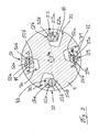
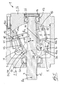
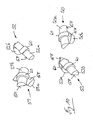
- the hydrostatic axial piston machine 1 designed as a bent-axis machine according to the FIG. 1 has a housing 2, which consists of a housing pot 2a and a housing cover 2b.
- a housing 2 a provided with a drive flange 3 drive shaft 4 by means of bearings 5a, 5b about a rotation axis R t is rotatably supported.
- the drive flange 3 is integrally formed on the drive shaft 4.
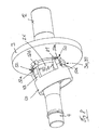
- a cylinder drum 7 is arranged in the housing 2, which is provided with a plurality of KolbenausEnglishept 8, which are arranged concentrically to a rotation axis R z of the cylinder drum 7.
- a piston 10 is arranged longitudinally displaceable.
- the rotation axis R t of the drive shaft 4 intersects the rotation axis R z of the cylinder drum 7 at the point of intersection S.
- the cylinder drum 7 is provided with a central, concentric with the axis of rotation R z of the cylinder drum 7 arranged longitudinal recess 11 through which the drive shaft 4 extends therethrough.
- the drive shaft 4 guided through the axial piston machine is mounted on both sides of the cylinder drum 7 by means of the bearings 5a, 5b.
- the drive shaft 4 is mounted with the bearing 5a in the housing pot 2a and with the bearing 5b in the housing cover 2b.
- the drive shaft 4 is designed at the drive flange end with a torque transmission means 12, for example a spline, for introducing a drive torque or tapping off an output torque.
- the opposite, cylindrical drum-side end of the drive shaft 4 can also be provided with a torque transmitting means to achieve a drive through the axial piston machine 1.
- a torque can be passed through the axial piston machine 1 or in a designed as a motor Axialkolbenmaschen a two-sided output possible.
- a through hole 13 is formed for the drive shaft 4, which is closed by a cover 14 in the illustrated embodiment.
- the in the FIG. 1 shown axial piston machine is designed as a constant machine with a fixed displacement volume, wherein the axis of rotation R z of the cylinder drum 7 to the rotation axis R t of the drive shaft 4 has a fixed tilt angle or swivel angle ⁇ .
- the cylinder drum 7 is located to control the supply and discharge of pressure medium in the displacers V formed by the piston recesses 8 and the piston 10 at a formed on the housing cover 2b control surface 15 which is provided with not shown kidney-shaped control recesses having an inlet port 16 and an outlet port of the axial piston machine 1 form.
- the cylinder drum 7 is provided with a control opening 18 on each piston recess 8.
- the pistons 10 are each hinged to the drive flange 3.
- each formed as a spherical joint articulation 20 is formed between the respective piston 10 and the drive flange 3 .
- the articulation 20 is formed in the illustrated embodiment as a ball joint, which is formed by a ball head 10a of the piston 10 and a spherical cap 3a in the drive flange 3, in which the piston 10 is attached to the ball head 10a.
- the pistons 10 each have a collar portion 10b, with which the piston 10 is arranged in the piston recess 8.
- a piston rod 10c of the piston 10 connects the collar portion 10b with the ball head 10b.
- the collar portion 10b of the piston 10 is arranged with play in the piston recess 8.
- the collar portion 10b of the piston 10 may be designed to be spherical.
- a sealing means 21 for example a piston ring, is arranged on the collar portion 10b of the piston 10.
- a spherical guide 25 is formed between the cylinder drum 7 and the drive shaft 4.
- the spherical guide 25 is formed by a spherical portion 26 of the drive shaft 4, on which the cylinder drum 7 is arranged with a arranged in the region of the central longitudinal recess 11 hollow spherical portion 27.
- the center of the sections 26, 27 lies on the intersection point S of the axis of rotation R t of the drive shaft 4 and the axis of rotation R z of the cylinder drum 7.
- the centers M of the articulated connections 20 of the pistons 10 with the drive flange 3 are arranged completely outside the cylinder drum 7 in the longitudinal direction of the cylinder drum 7.
- the centers M of the articulated connections 20 are thus always outside the longitudinal extension of the cylinder drum 7 when the cylinder drum 7 rotates about the axis of rotation R z .
- a driving joint 30 is arranged between the drive shaft 4 and the cylinder drum 7, which couples the drive shaft 4 and the cylinder drum 7 in the direction of rotation.
- the driving joint 30 is formed as a constant velocity joint, which allows a rotationally synchronous entrainment of the cylinder drum 7 with the drive shaft 4, so that a uniform, synchronous rotation of the cylinder drum 7 with the drive shaft 4 results.
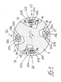
- a constant velocity joint driving joint 30 is formed as a cone beam half-roll joint 31.
- the cone-beam half-roll joint 31 is formed by a plurality of roller pairs 50, 51, 52, 53, which are arranged between the drive shaft 4 and a sleeve-shaped driver element 40 connected in a rotationally fixed manner to the cylinder drum 7.
- the sleeve-shaped driver element 40 is arranged in the central longitudinal recess 11 of the cylinder drum 7.
- the driver element 40 is on the cylinder drum. 7 secured in the longitudinal direction of the cylinder drum 7 in the axial direction and in the circumferential direction.
- the driver element 40 rests with an end face against a diameter shoulder 11a of the longitudinal recess 11.
- the rotation is effected by means of a securing means 45, which is formed in the illustrated embodiment by a arranged between the sleeve-shaped driver element 40 and the cylinder drum 7 connecting pin.
- the drive shaft 4 guided through the axial piston machine 1 also extends through the sleeve-shaped driver element 40.
- Each of the plurality of roller pairs 50-53 of the cone-beam half-roller joint 31 consists of two and thus a pair of semi-cylindrical half rollers 50a, 50b, 51a, 51b, 52a, 52b, 53a, 53b.
- the semi-cylindrical half rollers 50a, 50b, 51a, 51b, 52a, 52b, 53a, 53b are - as in connection with the FIG. 10 is illustrated - each of substantially to a rotational axis RR t , RR z flattened cylindrical body.
- the paired half rollers 50a, 50b, 51a, 51b, 52a, 52b, 53a, 53b form flat sliding surfaces GF, on which the two half rollers 50a, 50b, 51a, 51b, 52a, 52b, 53a , 53b of a pair of rollers 50, 51, 52, 53 abut one another to form a surface contact.
- the half rollers 50a, 50b, 51a, 51b, 52a, 52b, 53a, 53b are arranged in the radial direction within the pitch circle of the pistons 10 and spaced from the axes of rotation R t , R z .
- the cone-beam half-roll joint 31 can therefore be arranged to save space within the pitch circle of the pistons 10.
- Each roller pair 50-53 has a cylindrical drum-side half-roller 50a, 51a, 52a, 53a belonging to the cylinder drum 7 and a drive shaft 4 belonging to the drive shaft side half-roller 50b, 51b, 52b, 53b, which abut the flat sliding surfaces GF and each other stay in contact.
- the cylindrical drum-side half roller 50a, 51a, 52a, 53a of the corresponding roller pair 50-53 are each in a cylindrical, in particular partially cylindrical, cylinder drum side receptacle 55a, 56a, 57a, 58a and the drive shaft side half roller 50b, 51b, 52b, 53b of a roller pair 50th -53 in a cylindrical, in particular part-cylindrical, drive shaft side receiving 55b, 56b, 57b, 58b added.
- the half rollers 50a, 51a, 52a, 53a, 50b, 51b, 52b, 53b are secured in the respective cylindrical receptacle 55a, 56a, 57a, 58a, 55b, 56b, 57b, 58b in the longitudinal direction of the corresponding axis of rotation.
- each half-rollers 50a, 51a, 52a, 53a, 50b, 51b, 52b, 53b are provided in the cylindrical portion with a collar 60 which in a groove 61 of the corresponding receptacle 55a, 56a, 57a, 58a, 55b, 56b , 57b, 58b.
- the drive shaft-side half-roller 50b is shown by the roller pair 50 with thick lines and the cylindrical drum-side half-roller 50a resting on the half-roller 50b is shown with thin lines.
- the cylindrical drum-side half roller 51a is shown with thick lines and the thin shaft on the half roller 51a resting on the drive shaft side half roller 51 b.
- the half rollers 50b and 51a are in the sectional plane of the FIG. 2 lying flattened, flat sliding surfaces GF shown.
- the rotational axes RR z of the cylinder-drum-side half rollers 50a, 51a, 52a, 53a are inclined to the rotation axis R z of the cylinder drum 7 by an inclination angle ⁇ .
- the rotation axes RR z of the cylindrical drum-side half rollers 50a, 51a, 52a, 53a intersect the rotation axis R z of the cylinder drum 7 at the point of intersection S z .
- the individual rotation axes RR z of the plurality of cylindrical drum-side half rollers 50a, 51a, 52a, 53a form one in the FIG. 2 illustrated cone beam about the rotation axis R z of the cylinder drum 7 with the tip at the intersection S z .
- the inclination angles ⁇ of the rotation axes RR z of the cylinder drum side half rollers 50a, 51a, 52a, 53a to the rotation axis R z of the cylinder drum 7 and the rotation axes RR t of the drive shaft side half rollers 50b, 51b, 52b, 53b to the rotation axis R t of the drive shaft 4 are identical in magnitude .
- the inclination angles ⁇ of the rotation axes RR z , RR t of the half rollers of the drive shaft 4 and the cylinder drum 7 to be coupled together are thus the same.
- the plane E is therefore inclined at half the inclination angle or swivel angle ⁇ / 2 with respect to a plane E 1 perpendicular to the axis of rotation R t of the drive shaft 4 and a plane E 2 perpendicular to the axis of rotation R z of the cylinder drum 7.
- the plane E passes through the intersection S of the axes of rotation R t , R z .
- the half rollers 50a, 50b, 51a, 51b, 52a, 52b, 53a, 53b of the respective roller pair 50, 51, 52, 53 are arranged in the region of the points of intersection SP of the axes of rotation RR t , RR z , whereby at the intersections SP of the two Half rolls of the respective roller pair 50-53, the power transmission between the flat sliding surface GF takes place to take the cylinder drum 7.
- each paired half rollers 50a, 50b, 51a, 51b, 52a, 52b, 53a, 53b Due to the inclination of the axes of rotation RR t , RR z of each paired half rollers 50a, 50b, 51a, 51b, 52a, 52b, 53a, 53b to each other by rotation in the corresponding receptacles 55a, 56a, 57a, 58a, 55b , 56b, 57b, 58b align the flat surfaces and thus the sliding surfaces GF of the adjacent half rollers to each other.
- the in the FIG. 1 illustrated axial piston machine 1 is operable in both directions of rotation.
- at least one pair of rollers 50-53 is provided for each direction of rotation and thus torque direction of the driving torque for the entrainment of the cylinder drum 7.
- the roller pairs 50, 51 serve to entrain the cylinder drum 7 in a rotation of the drive shaft 4 in the counterclockwise direction.
- FIG. 3 are for this direction of rotation of the drive shaft 4 to the flat sliding surfaces GF of the half rollers 50a, 50b and 51a, 51b of the roller pairs 50, 51 transmitted forces F1, F2, which generate the driving torque M2 for driving the cylinder drum 7, shown.
- the torque M1 is applied via the drive shaft 4 and the forces F1 are applied to the drive shaft-side half rollers 50b, 51b, which generate the take-up torque M2 for driving the cylinder drum 7 via the forces F2 occurring on the cylinder-drum-side half rollers 50a, 51a.
- the roller pairs serve 52, 53 for driving the cylinder drum 7 in an opposite rotation of the drive shaft 4 clockwise.
- FIG. 4 are for this direction of rotation of the drive shaft 4 to the flat sliding surfaces GF of the half rollers 52a, 52b and 53a, 53b of the roller pairs 52, 53 transmitted from the force acting on the drive shaft 4 torque M1 forces F1, F2, the driving torque M2 for driving the cylinder drum 7 generate, shown.
- the torque M1 is applied via the drive shaft 4, and the forces F1 are applied to the drive shaft-side half rollers 52b, 53b, which generate the take-up torque M2 for driving the cylinder drum 7 via the forces F2 occurring on the cylinder-drum-side half rollers 52a, 53a.
- two pairs of rollers 50, 51 and 52, 53 are provided for each direction of rotation, wherein the pairs of rollers 50, 51 for the first direction of rotation and the roller pairs 52, 53 for the second direction of rotation are distributed uniformly over the circumference.
- a radial force balance can be achieved.
- the pairs of rollers 50, 51 are arranged offset by a rotation angle of 180 ° and the pairs of rollers 52, 53 offset by a rotation angle of 180 °.
- the roller pairs 50, 51 for the first direction of rotation are offset from the pairs of rollers 52, 53 for the second direction of rotation by a rotation angle of 90 °.
- the drive shaft side receptacles 55 b, 56 b, 57 b, 58 b are formed in the drive shaft 4 for the drive shaft side half rollers 50 b, 51 b, 52 b, 53 b.
- the drive shaft 4 is provided for this purpose with pocket-shaped recess 70, 71, 72, 73, on whose side surfaces in each case a drive shaft-side receptacle 55b, 56b, 57b, 58b is formed.
- the cylindrical drum side receptacles 55a, 56a, 57a, 58a for the cylindrical drum side half rollers 50a, 51a, 52a, 53a are formed in the sleeve-shaped driving element 40.
- the sleeve-shaped driver element 40 is for this purpose provided with finger-shaped elevations 41, 42, 43, 44, which extend in the direction of the drive shaft 4 and in which in each case a cylindrical drum-side receptacle 55 a, 56 a, 57, 58 a is formed.
- the sleeve-shaped driver element 40 is further provided with the hollow spherical portion 27 of the spherical guide 25.
- Each finger-shaped elevation 41, 42, 43, 44 of the driver element 40 engages in an associated pocket-shaped recess 70, 71, 72, 73 of the drive shaft 4 a.
- FIGS. 5 to 7 Further embodiments of an axial piston according to the invention are shown in a bent-axis design, with the FIG. 1 identical components are provided with identical reference numerals.
- the in the FIGS. 5 to 7 Embodiments shown are in terms of the execution of the cone beam half-roller joint 31 for driving the cylinder drum 7 with the FIGS. 1 to 4 and 8 to 13 identical.
- the axial piston machine 1 of FIG. 5 is designed as an adjusting machine with a variable displacer volume.
- the adjustment of the inclination angle ⁇ of the axis of rotation R z of the cylinder drum 7 with respect to the axis of rotation R t of the drive shaft 4 is adjustable to change the displacer volume.
- the control surface 15 against which the cylinder drum 7 abuts is for this purpose formed on a weighing body 100, which is arranged pivotably in the housing 2 about a pivot axis SA.
- the pivot axis SA of the weighing body 100 and thus the cylinder drum 7 is located at the intersection S of the axis of rotation R t of the drive shaft 4 and the axis of rotation R z of the cylinder drum 7 and is perpendicular to the axes of rotation R t and R z .
- the inclination angle ⁇ of the rotation axis R z of the cylinder drum 7 changes to the rotation axis R t of the drive shaft 4.
- the cylinder drum 7 can be pivoted to a zero position in which the rotation axis R z of the cylinder drum 7 coaxial with the axis of rotation R t the drive shaft 4 is. Starting from this zero position, the cylinder drum 7 can be entangled to one or both sides, so that the axial piston machine of FIG. 5 can be executed as unilaterally pivotable or as two-sided pivotable adjusting.
- a device for pivoting the weighing body 100 and thus the cylinder drum 7 is in the FIG. 5 not shown in detail.
- FIG. 6 an embodiment of the axial piston machine 1 is shown, in which the centers M of the joints 20 of the piston 120 are arranged with the drive flange 4 in the longitudinal direction of the cylinder drum 7 at least partially within the cylinder drum 7.
- the centers M of the articulated connections 20 are arranged at least partially within the longitudinal extent of the cylinder drum 7 during rotation of the cylinder drum 7.
- a dimension L illustrates, by which the centers M of the articulated joints 20 protrude into the piston recesses 8 of the cylinder drum 7.
- finger-shaped elevations 3 b are formed on the end face of the drive flange 3 facing the cylinder drum 7, at whose ends the spherical caps 3 a of the articulated connections 20 are arranged.
- roller pairs 50-53 of the cone-beam half-roller joint 31 are in the FIG. 6 seen in the longitudinal direction of the cylinder drum 7 at least partially disposed within the cylinder drum 7.
- FIG. 6 allows a longitudinal direction of the drive shaft 4 compact design of the axial piston 1. Further arises between the drive shaft 4 and the cylinder drum 7, a larger space. This increased clearance can be used to increase the pivot angle ⁇ of the cylinder drum 7 and thus to increase the power density of the axial piston machine 1 and / or to increase the diameter of the drive shaft 4 thus increasing the through-drive torque.
- axial piston machine 1 is instead of the two-sided storage of the drive shaft 4 in the housing 2 according to the FIGS. 1 . 5 and 6 provided with the drive flange 3 drive shaft 4 by means of the two bearings 5a, 5b on one side and thus cantilevered.
- the axial piston machine 1 of FIG. 7 is designed as an adjusting machine. It is understood that the axial piston machine can alternatively be designed as a constant machine.
- the central longitudinal recess 11 of the cylinder drum 7 can also be dispensed with.
- An axial piston machine 1 according to the invention with a cone beam half-roller joint 31 for entrainment of the cylinder drum 7 has a number of advantages.
- the bevel beam half-roll joint 31 can be easily designed as a homokinetic constant velocity joint by appropriate choice of the inclination angle ⁇ of the axes of rotation RR z , RR t of the half-rollers.
- the inventive, designed as constant velocity joint cone beam half-roll joint 31 is suitable for axial piston machines 1 with a constant or an adjustable displacement volume. In an adjusting machine occurs when swinging back the cylinder drum 7 to a reduced displacement volume no backlash.
- the drive shaft 4 can be mounted on both sides of the cylinder drum 7 in the housing 2, whereby advantages in terms of a compact design of the axial piston machine 1 are achieved in the axial direction.
- the cone-beam half-roll joint 31 has a surface contact. Due to the surface contact on the flat sliding surfaces GF of the two half rollers of a pair of rollers 51-53 occur only small Hertzian pressure, whereby the cone beam half-roller joint 31 of the invention is insensitive and robust against overload, which may arise for example by a high spin.
- the cone-beam half-roll joint 31 is therefore suitable for an axial piston machine 1, preferably a hydraulic motor, in applications with high rotational accelerations.
- the function torque entrainment of the cylinder drum 7 by the cone-beam half-roll joint 31 and the function storage of the cylinder drum 7 by the spherical guide 25 are separated. Both functions are simple and inexpensive to manufacture by the required, geometrically simple surfaces and components. In particular, the receptacles for the half rolls of the cone-beam half-roll joint 31 and the half-rolls themselves can be produced in a simple and cost-effective manner.
- the invention is not limited to the illustrated embodiments.
- the embodiment of the FIG. 6 can also be performed as adjusting machine as a constant machine as an alternative to the illustrated embodiment.
- an arrangement and immersion of the centers M of the articulated joints 20 in the piston recess according to the FIG. 6 be realized.
- the axial piston of the FIGS. 1 . 5 . 6 and 7 instead of being operable in both directions Axialkolbenmaschine1 be executed operable only in a single direction of rotation, wherein the conical beam half-roller joint 31 is simplified accordingly.
- the cone beam half roller joint 31 is not limited to the illustrated number of roller pairs. It is understood that for higher to be transmitted driving torques M2 of the cylinder drum 7 instead of two pairs of rollers per direction of rotation a higher number of roller pairs can be used. Accordingly, only a single pair of rollers per direction of rotation can be provided for lower to be transmitted driving torques M2 of the cylinder drum 7.
- a pair of rollers or several pairs of rollers are required correspondingly only for the desired direction of rotation in order to be able to transmit the driving torques M2 of the cylinder drum 7.
- the drive shaft-side receptacles 55b, 56b, 57b, 58b for receiving and supporting the drive shaft side half rollers 50b, 51b, 52b, 53b may alternatively be formed in a training in the drive shaft 4 in the drive flange 3 or a non-rotatably connected to the drive shaft 4 component ,
- the drive flange 3 and the drive shaft 4 can also be made split, wherein the drive flange 3 via a suitable torque transmitting means, such as a toothing, with the drive shaft 4 is rotatably connected.
- the drive shaft side receptacles 55b, 56b, 57b, 58b for ballast of the drive shaft side half rollers 50b, 51b, 52b, 53b can also be optionally arranged in the drive flange 3 or the drive shaft 4 in such a split embodiment of the drive shaft 4 and the drive flange.
- the cylinder drum-side receptacles 55a, 56a, 57a, 58a for receiving and supporting the cylindrical drum side half rollers 50a, 51a, 52a, 53a may alternatively be formed on the sleeve-shaped driver element 40 directly on the cylinder drum 7, the preferred for this purpose with the finger-shaped Elevations 41, 42, 43, 44 is provided.
Landscapes
- Engineering & Computer Science (AREA)
- General Engineering & Computer Science (AREA)
- Mechanical Engineering (AREA)
- Chemical & Material Sciences (AREA)
- Combustion & Propulsion (AREA)
- Reciprocating Pumps (AREA)
- Hydraulic Motors (AREA)
Applications Claiming Priority (1)
| Application Number | Priority Date | Filing Date | Title |
|---|---|---|---|
| DE201310108406 DE102013108406A1 (de) | 2013-08-05 | 2013-08-05 | Hydrostatische Axialkolbenmaschine in Schrägachsenbauweise |
Publications (2)
| Publication Number | Publication Date |
|---|---|
| EP2835531A2 true EP2835531A2 (fr) | 2015-02-11 |
| EP2835531A3 EP2835531A3 (fr) | 2015-07-15 |
Family
ID=51260729
Family Applications (1)
| Application Number | Title | Priority Date | Filing Date |
|---|---|---|---|
| EP14179555.9A Withdrawn EP2835531A3 (fr) | 2013-08-05 | 2014-08-01 | Machine à piston axial hydrostatique dans une construction à axe oblique |
Country Status (5)
| Country | Link |
|---|---|
| US (1) | US9617984B2 (fr) |
| EP (1) | EP2835531A3 (fr) |
| JP (1) | JP6395492B2 (fr) |
| CN (1) | CN104343467A (fr) |
| DE (1) | DE102013108406A1 (fr) |
Families Citing this family (1)
| Publication number | Priority date | Publication date | Assignee | Title |
|---|---|---|---|---|
| CN112664386A (zh) * | 2020-12-19 | 2021-04-16 | 王建设 | 一种压斜式水动力机 |
Citations (3)
| Publication number | Priority date | Publication date | Assignee | Title |
|---|---|---|---|---|
| DE2805492C2 (de) | 1978-02-09 | 1982-10-07 | Linde Ag, 6200 Wiesbaden | Anordnung zum Kühlen der Kolben bei einer hydraulischen Axialkolbenmaschine |
| DE3800031C2 (fr) | 1988-01-04 | 1992-04-30 | Hans Dipl.-Ing. Dr.-Ing.E.H. 7502 Malsch De Molly | |
| DE102009005390A1 (de) | 2009-01-21 | 2010-07-22 | Robert Bosch Gmbh | Axialkolbenmaschine in Schrägachsenbauweise |
Family Cites Families (8)
| Publication number | Priority date | Publication date | Assignee | Title |
|---|---|---|---|---|
| US2633104A (en) * | 1949-07-15 | 1953-03-31 | Borg Warner | Motor port construction |
| GB1069671A (en) * | 1963-06-19 | 1967-05-24 | Lucas Industries Ltd | Hydraulic reciprocating pumps and motors |
| US3566746A (en) * | 1969-04-29 | 1971-03-02 | Nemo Corp | Hydraulic steering system for boats |
| JPH0631612B2 (ja) * | 1984-11-12 | 1994-04-27 | 株式会社島津製作所 | ピストンポンプまたはモ−タ |
| SE465281B (sv) * | 1987-09-18 | 1991-08-19 | Volvo Hydraulik Ab | Ansaettningsanordning foer cylindertrumman vid en axialkolvmaskin med variabelt deplacement |
| JPH09250447A (ja) * | 1996-03-15 | 1997-09-22 | Hitachi Ltd | 流体供給ポンプ及び燃料供給ポンプ |
| DE102005057988A1 (de) | 2005-08-04 | 2007-02-08 | Bosch Rexroth Ag | Axialkolbenmaschine |
| DE102007011441A1 (de) * | 2007-03-08 | 2008-09-11 | Robert Bosch Gmbh | Axialkolbenmaschine |
-
2013
- 2013-08-05 DE DE201310108406 patent/DE102013108406A1/de not_active Withdrawn
-
2014
- 2014-08-01 US US14/449,191 patent/US9617984B2/en not_active Expired - Fee Related
- 2014-08-01 EP EP14179555.9A patent/EP2835531A3/fr not_active Withdrawn
- 2014-08-04 CN CN201410379419.2A patent/CN104343467A/zh active Pending
- 2014-08-05 JP JP2014159587A patent/JP6395492B2/ja active Active
Patent Citations (3)
| Publication number | Priority date | Publication date | Assignee | Title |
|---|---|---|---|---|
| DE2805492C2 (de) | 1978-02-09 | 1982-10-07 | Linde Ag, 6200 Wiesbaden | Anordnung zum Kühlen der Kolben bei einer hydraulischen Axialkolbenmaschine |
| DE3800031C2 (fr) | 1988-01-04 | 1992-04-30 | Hans Dipl.-Ing. Dr.-Ing.E.H. 7502 Malsch De Molly | |
| DE102009005390A1 (de) | 2009-01-21 | 2010-07-22 | Robert Bosch Gmbh | Axialkolbenmaschine in Schrägachsenbauweise |
Also Published As
| Publication number | Publication date |
|---|---|
| JP6395492B2 (ja) | 2018-09-26 |
| US9617984B2 (en) | 2017-04-11 |
| CN104343467A (zh) | 2015-02-11 |
| US20150075365A1 (en) | 2015-03-19 |
| DE102013108406A1 (de) | 2015-02-05 |
| JP2015031290A (ja) | 2015-02-16 |
| EP2835531A3 (fr) | 2015-07-15 |
Similar Documents
| Publication | Publication Date | Title |
|---|---|---|
| DE2343540C3 (de) | Gleichgang-Universalgelenk des Tripod-Typs | |
| DE2633578C2 (de) | Vibrator mit verstellbarer Schwungmasse | |
| EP2937567B1 (fr) | Machine à piston axial hydrostatique dans une construction à axe oblique dotée d'un élément articulé d'entraînement destiné à l'entraînement d'un tambour cylindrique | |
| WO2023227157A1 (fr) | Agencements de direction pour un véhicule et véhicule ayant une colonne de direction et un agencement de direction | |
| DE19506815A1 (de) | Homokinetisches Gelenk und dieses Gelenk verwendende Axialkolbenpumpe | |
| DE2626170A1 (de) | Differenzialgetriebe | |
| DE10226106A1 (de) | Antriebsstrang-Winkelreduziereinrichtung | |
| DE102008046821B4 (de) | Kurbelwelle für eine Brennkraftmaschine mit varibaler Verdichtung und Brennkraftmaschine mit variabler Verdichtung | |
| EP2848806B1 (fr) | Machine à piston axial hydrostatique dans une construction à axe oblique dotée d'un joint homocinétique destiné à l'entraînement d'un tambour cylindrique | |
| EP2835531A2 (fr) | Machine à piston axial hydrostatique dans une construction à axe oblique | |
| DE10154921A1 (de) | Hydrostatische Axialkolbenmaschine in Triebflanschbauweise | |
| DE102009027855B3 (de) | Gleichlauf-Universalgelenk | |
| DE102008001490A1 (de) | Einstufiges Taumelradgetriebe mit Stirnverzahnung | |
| EP2848807B1 (fr) | Machine à piston axial hydrostatique dans une construction à axe oblique | |
| DE60110314T2 (de) | Axialkolbenpumpe | |
| DE102013222602A1 (de) | Hydrostatische Axialkolbenmaschine | |
| EP0736377B1 (fr) | Rouleau de transport de feuilles avec correction de repérage diagonal | |
| DE102015100620A1 (de) | Hydrostatische Axialkolbenmaschine in Schrägachsenbauweise mit einem Gleichlaufgelenk zur Mitnahme der Zylindertrommel | |
| DE3625429C2 (fr) | ||
| EP3211230A1 (fr) | Machine à piston axial, en particulier pompe à pistons axiaux | |
| DE102015100621A1 (de) | Hydrostatische Axialkolbenmaschine in Schrägachsenbauweise mit einem Mitnahmegelenk zur Mitnahme der Zylindertrommel | |
| DE2262026A1 (de) | Axialkolbenmaschine | |
| EP2930360A2 (fr) | Machine à piston axial dans une construction à axe oblique avec patins de guidage dans le plateau d'entraînement | |
| DE3712810A1 (de) | Gleichlaufdrehgelenk und anwendung desselben | |
| DE3125210A1 (de) | "wellenkupplung" |
Legal Events
| Date | Code | Title | Description |
|---|---|---|---|
| PUAI | Public reference made under article 153(3) epc to a published international application that has entered the european phase |
Free format text: ORIGINAL CODE: 0009012 |
|
| 17P | Request for examination filed |
Effective date: 20140801 |
|
| AK | Designated contracting states |
Kind code of ref document: A2 Designated state(s): AL AT BE BG CH CY CZ DE DK EE ES FI FR GB GR HR HU IE IS IT LI LT LU LV MC MK MT NL NO PL PT RO RS SE SI SK SM TR |
|
| AX | Request for extension of the european patent |
Extension state: BA ME |
|
| PUAL | Search report despatched |
Free format text: ORIGINAL CODE: 0009013 |
|
| AK | Designated contracting states |
Kind code of ref document: A3 Designated state(s): AL AT BE BG CH CY CZ DE DK EE ES FI FR GB GR HR HU IE IS IT LI LT LU LV MC MK MT NL NO PL PT RO RS SE SI SK SM TR |
|
| AX | Request for extension of the european patent |
Extension state: BA ME |
|
| RIC1 | Information provided on ipc code assigned before grant |
Ipc: F04B 1/32 20060101ALI20150608BHEP Ipc: F04B 1/20 20060101AFI20150608BHEP Ipc: F03C 1/06 20060101ALI20150608BHEP |
|
| R17P | Request for examination filed (corrected) |
Effective date: 20151221 |
|
| RBV | Designated contracting states (corrected) |
Designated state(s): AL AT BE BG CH CY CZ DE DK EE ES FI FR GB GR HR HU IE IS IT LI LT LU LV MC MK MT NL NO PL PT RO RS SE SI SK SM TR |
|
| STAA | Information on the status of an ep patent application or granted ep patent |
Free format text: STATUS: REQUEST FOR EXAMINATION WAS MADE |
|
| STAA | Information on the status of an ep patent application or granted ep patent |
Free format text: STATUS: THE APPLICATION IS DEEMED TO BE WITHDRAWN |
|
| 18D | Application deemed to be withdrawn |
Effective date: 20200303 |