EP2835568A1 - Raccord de tube, climatiseur, procédé de production de tube de raccordement, tube de raccordement et procédé de raccordement - Google Patents
Raccord de tube, climatiseur, procédé de production de tube de raccordement, tube de raccordement et procédé de raccordement Download PDFInfo
- Publication number
- EP2835568A1 EP2835568A1 EP13772404.3A EP13772404A EP2835568A1 EP 2835568 A1 EP2835568 A1 EP 2835568A1 EP 13772404 A EP13772404 A EP 13772404A EP 2835568 A1 EP2835568 A1 EP 2835568A1
- Authority
- EP
- European Patent Office
- Prior art keywords
- connecting pipe
- pipe joint
- pipe
- face
- bead
- Prior art date
- Legal status (The legal status is an assumption and is not a legal conclusion. Google has not performed a legal analysis and makes no representation as to the accuracy of the status listed.)
- Granted
Links
Images





Classifications
-
- F—MECHANICAL ENGINEERING; LIGHTING; HEATING; WEAPONS; BLASTING
- F16—ENGINEERING ELEMENTS AND UNITS; GENERAL MEASURES FOR PRODUCING AND MAINTAINING EFFECTIVE FUNCTIONING OF MACHINES OR INSTALLATIONS; THERMAL INSULATION IN GENERAL
- F16L—PIPES; JOINTS OR FITTINGS FOR PIPES; SUPPORTS FOR PIPES, CABLES OR PROTECTIVE TUBING; MEANS FOR THERMAL INSULATION IN GENERAL
- F16L19/00—Joints in which sealing surfaces are pressed together by means of a member, e.g. a swivel nut, screwed on, or into, one of the joint parts
- F16L19/02—Pipe ends provided with collars or flanges, integral with the pipe or not, pressed together by a screwed member
- F16L19/0212—Pipe ends provided with collars or flanges, integral with the pipe or not, pressed together by a screwed member using specially adapted sealing means
-
- B—PERFORMING OPERATIONS; TRANSPORTING
- B21—MECHANICAL METAL-WORKING WITHOUT ESSENTIALLY REMOVING MATERIAL; PUNCHING METAL
- B21D—WORKING OR PROCESSING OF SHEET METAL OR METAL TUBES, RODS OR PROFILES WITHOUT ESSENTIALLY REMOVING MATERIAL; PUNCHING METAL
- B21D17/00—Forming single grooves in sheet metal or tubular or hollow articles
- B21D17/02—Forming single grooves in sheet metal or tubular or hollow articles by pressing
- B21D17/025—Forming single grooves in sheet metal or tubular or hollow articles by pressing by pressing tubes axially
-
- B—PERFORMING OPERATIONS; TRANSPORTING
- B21—MECHANICAL METAL-WORKING WITHOUT ESSENTIALLY REMOVING MATERIAL; PUNCHING METAL
- B21D—WORKING OR PROCESSING OF SHEET METAL OR METAL TUBES, RODS OR PROFILES WITHOUT ESSENTIALLY REMOVING MATERIAL; PUNCHING METAL
- B21D19/00—Flanging or other edge treatment, e.g. of tubes
- B21D19/08—Flanging or other edge treatment, e.g. of tubes by single or successive action of pressing tools, e.g. vice jaws
-
- B—PERFORMING OPERATIONS; TRANSPORTING
- B21—MECHANICAL METAL-WORKING WITHOUT ESSENTIALLY REMOVING MATERIAL; PUNCHING METAL
- B21D—WORKING OR PROCESSING OF SHEET METAL OR METAL TUBES, RODS OR PROFILES WITHOUT ESSENTIALLY REMOVING MATERIAL; PUNCHING METAL
- B21D39/00—Application of procedures in order to connect objects or parts, e.g. coating with sheet metal otherwise than by plating; Tube expanders
- B21D39/04—Application of procedures in order to connect objects or parts, e.g. coating with sheet metal otherwise than by plating; Tube expanders of tubes with tubes; of tubes with rods
-
- F—MECHANICAL ENGINEERING; LIGHTING; HEATING; WEAPONS; BLASTING
- F16—ENGINEERING ELEMENTS AND UNITS; GENERAL MEASURES FOR PRODUCING AND MAINTAINING EFFECTIVE FUNCTIONING OF MACHINES OR INSTALLATIONS; THERMAL INSULATION IN GENERAL
- F16L—PIPES; JOINTS OR FITTINGS FOR PIPES; SUPPORTS FOR PIPES, CABLES OR PROTECTIVE TUBING; MEANS FOR THERMAL INSULATION IN GENERAL
- F16L15/00—Screw-threaded joints; Forms of screw-threads for such joints
- F16L15/04—Screw-threaded joints; Forms of screw-threads for such joints with additional sealings
-
- F—MECHANICAL ENGINEERING; LIGHTING; HEATING; WEAPONS; BLASTING
- F16—ENGINEERING ELEMENTS AND UNITS; GENERAL MEASURES FOR PRODUCING AND MAINTAINING EFFECTIVE FUNCTIONING OF MACHINES OR INSTALLATIONS; THERMAL INSULATION IN GENERAL
- F16L—PIPES; JOINTS OR FITTINGS FOR PIPES; SUPPORTS FOR PIPES, CABLES OR PROTECTIVE TUBING; MEANS FOR THERMAL INSULATION IN GENERAL
- F16L19/00—Joints in which sealing surfaces are pressed together by means of a member, e.g. a swivel nut, screwed on, or into, one of the joint parts
- F16L19/02—Pipe ends provided with collars or flanges, integral with the pipe or not, pressed together by a screwed member
- F16L19/0212—Pipe ends provided with collars or flanges, integral with the pipe or not, pressed together by a screwed member using specially adapted sealing means
- F16L19/0225—Pipe ends provided with collars or flanges, integral with the pipe or not, pressed together by a screwed member using specially adapted sealing means without sealing rings
-
- F—MECHANICAL ENGINEERING; LIGHTING; HEATING; WEAPONS; BLASTING
- F16—ENGINEERING ELEMENTS AND UNITS; GENERAL MEASURES FOR PRODUCING AND MAINTAINING EFFECTIVE FUNCTIONING OF MACHINES OR INSTALLATIONS; THERMAL INSULATION IN GENERAL
- F16L—PIPES; JOINTS OR FITTINGS FOR PIPES; SUPPORTS FOR PIPES, CABLES OR PROTECTIVE TUBING; MEANS FOR THERMAL INSULATION IN GENERAL
- F16L19/00—Joints in which sealing surfaces are pressed together by means of a member, e.g. a swivel nut, screwed on, or into, one of the joint parts
- F16L19/02—Pipe ends provided with collars or flanges, integral with the pipe or not, pressed together by a screwed member
- F16L19/025—Pipe ends provided with collars or flanges, integral with the pipe or not, pressed together by a screwed member the pipe ends having integral collars or flanges
- F16L19/028—Pipe ends provided with collars or flanges, integral with the pipe or not, pressed together by a screwed member the pipe ends having integral collars or flanges the collars or flanges being obtained by deformation of the pipe wall
-
- F—MECHANICAL ENGINEERING; LIGHTING; HEATING; WEAPONS; BLASTING
- F16—ENGINEERING ELEMENTS AND UNITS; GENERAL MEASURES FOR PRODUCING AND MAINTAINING EFFECTIVE FUNCTIONING OF MACHINES OR INSTALLATIONS; THERMAL INSULATION IN GENERAL
- F16L—PIPES; JOINTS OR FITTINGS FOR PIPES; SUPPORTS FOR PIPES, CABLES OR PROTECTIVE TUBING; MEANS FOR THERMAL INSULATION IN GENERAL
- F16L19/00—Joints in which sealing surfaces are pressed together by means of a member, e.g. a swivel nut, screwed on, or into, one of the joint parts
- F16L19/02—Pipe ends provided with collars or flanges, integral with the pipe or not, pressed together by a screwed member
- F16L19/025—Pipe ends provided with collars or flanges, integral with the pipe or not, pressed together by a screwed member the pipe ends having integral collars or flanges
- F16L19/028—Pipe ends provided with collars or flanges, integral with the pipe or not, pressed together by a screwed member the pipe ends having integral collars or flanges the collars or flanges being obtained by deformation of the pipe wall
- F16L19/0283—Pipe ends provided with collars or flanges, integral with the pipe or not, pressed together by a screwed member the pipe ends having integral collars or flanges the collars or flanges being obtained by deformation of the pipe wall and having a bell-mouthed shape
-
- F—MECHANICAL ENGINEERING; LIGHTING; HEATING; WEAPONS; BLASTING
- F25—REFRIGERATION OR COOLING; COMBINED HEATING AND REFRIGERATION SYSTEMS; HEAT PUMP SYSTEMS; MANUFACTURE OR STORAGE OF ICE; LIQUEFACTION SOLIDIFICATION OF GASES
- F25B—REFRIGERATION MACHINES, PLANTS OR SYSTEMS; COMBINED HEATING AND REFRIGERATION SYSTEMS; HEAT PUMP SYSTEMS
- F25B2500/00—Problems to be solved
- F25B2500/22—Preventing, detecting or repairing leaks of refrigeration fluids
- F25B2500/221—Preventing leaks from developing
Definitions
- the present disclosure relates to a pipe joint, an air conditioner, a method for producing a connecting pipe, a connecting pipe, and a connection method.
- a pipe joint in accordance with an application is utilized.
- a coolant pipe to allow a coolant of an air conditioner to flow is connected with a connection port of an indoor equipment of an air conditioner or an outdoor equipment thereof, in general, a flare pipe joint in compatible with JIS B 8607 is utilized (see, for example, Patent Literature 1).
- Patent Literature 1 Unexamined Japanese Patent Application Kokai Publication No. 2003-74768
- the present disclosure has been made in view of the aforementioned circumstances, and it is an objective to provide a pipe joint, an air conditioner, a method for producing a connecting pipe, a connecting pipe, and a connection method with an assurance of an excellent sealing performance.
- a pipe joint to be connected with a connecting pipe, and includes a pipe joint body and a nut member.
- the pipe joint body has a male thread formed on the outer circumference, and has a first insertion hole into which the connecting pipe is fitted, and which includes a first joining face joined with the connecting pipe.
- the nut member has a female thread to be engaged with the male thread, and a second insertion hole into which the connecting pipe is fitted and which includes a second joining face joined with the connecting pipe.
- a connecting pipe that has a bead which is expanded in the radial direction and which is formed at an end of the connecting pipe is connected, three sealed portions: a first sealed portion; a second sealed portion; and a third sealed portion are formed.
- a pipe joint, an air conditioner, a method for producing a connecting pipe, a connecting pipe, and a connection method with an assurance of an excellent sealing performance.
- FIGS. 1 to 8 An explanation will be below given of a pipe joint 10 and an air conditioner 100 according to a first embodiment of the present disclosure with reference to FIGS. 1 to 8 .
- an XYZ coordinate system is set and is referred as needed.
- the air conditioner 100 is utilized to adjust a temperature inside a room subjected to air conditioning.
- the air conditioner 100 includes indoor equipment 102, of outdoor equipment 103, and multiple connecting pipes 101 that connect the indoor equipment 102 with the outdoor equipment 103.
- the connecting pipe 101 is a piping through which a coolant forming a cooling cycle flows.
- An example coolant applied is R32 containing difluoromethane (CH 2 F 2 ).
- the indoor equipment 102 is installed in the room, and performs heat exchange with air in the room.
- the outdoor equipment 103 is installed outside the room, and performs heat exchange with air outside the room.
- each connecting pipe 101 is provided with a shut-off valve 104. The shut-off valve 104 shuts off the flow of the coolant in the connecting pipe 101, or releases the flow thereof.
- the pipe joint 10 is applied to connect the connecting pipe 101 with a connection port 102a of the indoor equipment 102.
- the pipe joint 10 includes a pipe joint body 20 and a nut member 30.
- a Z-axis direction corresponds to the axial direction of the pipe joint body 20 and that of the connecting pipe 101.
- the pipe joint body 20 is a substantially cylindrical member comprising a male thread 25 formed on an outer circumference.
- the pipe joint body 20 is formed of, for example, metal, such as stainless steel, steel, or an aluminum alloy, or, a resin.
- an insertion hole 21 (first insertion hole) is formed in the pipe joint body 20.
- the connecting pipe 101 is inserted in the insertion hole 21 from the +Z side, thereby forming a passage through which the coolant of the cooling cycle flows.
- a tapered face 22 (first joining face) is formed in the inner circumference of the insertion hole 21.
- the tapered face 22 is formed so as to be inclined relative to the Z-axis direction (axial direction of connecting pipe 101).
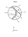
- An inclination angle ⁇ 1 of the tapered face 22 is, for example, 45 degrees. Still further, a straight hole face 23 is formed at the opening of the insertion hole 21 at the +Z side. This straight hole face 23 is formed in parallel with the Z-axis direction (axial direction of connecting pipe 101). As illustrated in FIG. 3 , the connection port 102a of the indoor equipment 102 is connected to the end of the pipe joint body 20 at the +Z side. The connection port 102a is connected by, for example, brazing.
- the nut member 30 is a hexagonal nut.
- the nut member 30 is formed of, for example, metal, such as stainless steel, steel, brass, or an aluminum alloy, or, a resin.
- An insertion hole 31 (second insertion hole) is formed in the nut member 30 so as to pass all the way therethrough in the Z-axis direction. A portion of the connecting pipe 101 where no bead 101a is formed is inserted in this insertion hole 31.
- a holding face 32 that holds the connecting pipe 101 in a position in the radial direction
- a female thread 33 to be engaged with the male thread 25 of the pipe joint body 20
- a tapered face 34 second joining face formed between the holding face 32 and the female thread 33.
- the tapered face 34 is formed so as to be inclined relative to the Z-axis direction (axial direction of connecting pipe 101). Still further, the tapered face 34 is formed so as to face the tapered face 22 of the pipe joint body 20, and holds the bead 101a of the connecting pipe 101 together with the tapered face 22.
- An inclination angle ⁇ 2 of this tapered face 34 is, for example, 45 degrees.
- the nut member 30 is formed in a shape in compliance with JIS B 8607. The present disclosure is not limited to this case, and the nut member 30 may be formed in shapes not in compliance with the JIS.
- a tapered face 24 (third joining face) inclined relative to the Z-axis direction is formed at an end face of the pipe joint body 20.
- the tapered face 24 is formed in parallel with the tapered face 34 of the insertion hole 31 of the nut member 30, and is joined with the tapered face 34 of the nut member 30 when the male thread 25 of the pipe joint body 20 is engaged with the female thread 33 of the nut member 30.
- an inclination angle ⁇ 3 of the tapered face 24 is, for example, 45 degrees consistent with the inclination angle ⁇ 2 of the tapered face 34.
- the connecting pipe 101 illustrated in FIG. 1 is piping that serves as a passage of the coolant flowing through between the indoor equipment 102 of the air conditioner 100 and the outdoor equipment 103 thereof.
- the connecting pipe 101 is, for example, a metal pipe (copper pipe).
- the connecting pipe 101 includes a connecting pipe body 101b, and the bead 101a.
- the bead 101a is formed at the end of the connecting pipe body 101b at the -Z side so as to expand like a balloon.
- the bead 101a includes a diameter-increasing portion 101c expanded in the radial direction from the connecting pipe body 101b, and a diameter-reducing portion 101d narrowed in the radial direction from the diameter-increasing portion 101c.
- the bead 101a is formed at the end of the connecting pipe body 101b at the -Z side.
- the present disclosure is, however, not limited to this case, and the bead may be formed at least a part of the connecting pipe body 101b.
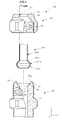
- the bead 101a of the connecting pipe 101 is formed using a conventional flaring tool (diameter enlarging jig) 50.
- the flaring tool 50 includes, for example, a flare dice (fastener jig) 51 that fastens the connecting pipe 101, and a flare cone (rotary punching jig) 52 that increases the diameter of the open end of the connecting pipe 101.
- a base pipe 110 comprising no bead 101a formed is prepared. This base pipe 110 is fitted with the above-explained nut member 30 in advance. Next, the base pipe 110 is fastened to the flare dice 51.
- the base pipe 110 is fitted in a through-hole 51a of the flare dice 51, and is tightened by, for example, a clamper in the radial direction to secure the base pipe 110 to the flare dice 51.
- This flare dice 51 is disposed at a position by a predetermined distance L (projection dimension) from the end of the base pipe 110 at the -Z direction.
- a tapered face 51b is formed in the edge of the opening of the through-hole 51a of the flare dice 51 at the -Z side.
- An inclination angle ⁇ 4 of this tapered face 51b is, for example, 45 degrees consistent with the inclination angle ⁇ 2 of the tapered face 34.
- the adapter 60 is a substantially cylindrical member formed with a flange 61, and is fitted from the -Z side of the base pipe 110. A surface of the flange 61 at the +Z side abuts the end of the base pipe 110 at the -Z side.
- the flare cone 52 of the flaring tool 50 is moved in the +Z direction while being rotated around the Z-axis.
- the flare cone 52 smoothly rotates relative to the adapter 60.
- the adapter 60 compresses the end of the base pipe 110 at the -Z side in the Z-axis direction.
- the compressed end of the base pipe 110 increases in the diameter, while at the same time, is deformed so as to expand like a balloon while being held by the tapered face 51b of the flare dice 51.
- the connecting pipe 101 formed with the bead 101a is finished.
- the bead 101a formed as explained above is held between the tapered face 22 of the insertion hole 21 of the pipe joint body 20 and the tapered face 34 of the insertion hole 31 of the nut member 30 in the Z-axis direction (axial direction of connecting pipe 101) and is fastened therebetween when the pipe joint body 20 is engaged with the nut member 30.
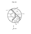
- a sealed portion S1 first sealed portion
- a sealed portion S2 second sealed portion
- the bead 101a of the connecting pipe 101 is held between the tapered face 22 of the pipe joint body 20 and the tapered face 34 of the nut member 30, while at the same time, abuts the straight hole face 23. Accordingly, the sealed portions S1, S2, and S4 are formed.
- the tapered face 34 of the nut member 30 is joined with the tapered face 24 of the pipe joint body 20, thereby forming the sealed portion S3.
- the leakage route E1 is a route in which the coolant travels along the outer circumference of the bead 101a of the connecting pipe 101, and leaks out from the holding face 32 of the nut member 30.
- the leakage route E2 is a route in which the coolant travels along the outer circumference of the bead 101a of the connecting pipe 101, and leaks out from the threaded portion between the male thread 25 and the female thread 33.
- the coolant leaks through the leakage route E2
- the coolant passes through the three locations: the sealed portion S1; the sealed portion S4; and the sealed portion S3.
- the remaining sealed portions S1 to S4 keep maintaining the sealed condition, and thus the coolant is prevented from leaking to the exterior of the pipe joint 10.
- this structure employs only one sealed portion. Accordingly, when there is concavity and convexity like scratches in the sealed portion between the flared portion and the pipe joint body, the sealing performance of the pipe joint is deteriorated, resulting in a leakage of the coolant.
- the four sealed portions S1 to S4 ensure the sealed condition, and thus even if there are concavity and convexity like scratches in any one of the sealed portion, the pipe joint 10 can appropriately prevent the coolant from leaking to the exterior of the pipe joint.
- the pipe joint 10 of this first embodiment includes the pipe joint body 20 and the nut member 30. Hence, it is unnecessary to additionally use components like a front ferule and a back ferule to be disposed between the pipe joint body 20 and the nut member 30 in order to enhance the sealing performance. Therefore, an increase of the production costs due to the increase of the number of components can be avoided.
- the connecting pipe 101 connected with the pipe joint 10 of this first embodiment is formed using a conventional flaring tool (diameter enlarging jig) 50 with the adapter 60 being fitted with the base pipe 110.
- a conventional flaring tool diameter enlarging jig
- the connecting pipe 101 easily formed with the bead 101a is easily obtainable.
- the variability of the work precision on the formed connecting pipe 101 can be reduced.
- the explanation was given of an example case in which the tapered face 22 of the insertion hole 21 of the pipe joint body 20 has the inclination angle ⁇ 1 of 45 degrees.
- the present disclosure is not limited to this case, and the inclination angle ⁇ 1 may be other degrees than 45 degrees.
- the inclination angle ⁇ 1 should be between 43 and 47 degrees, and further preferably, 45 degrees as indicated in this embodiment.
- the explanation was given of an example case in which the tapered face 34 of the insertion hole 31 of the nut member 30 has the inclination angle ⁇ 2 of 45 degrees.
- the present disclosure is not limited to this case, and the inclination angle ⁇ 2 may be other degrees than 45 degrees.
- the inclination angle ⁇ 2 should be between 43 and 47 degrees, and further preferably, 45 degrees as indicated in this embodiment.
- the explanation was given of an example case in which the tapered face 24 formed at the end face of the pipe joint body 20 has the inclination angle ⁇ 3 of 45 degrees.
- the present disclosure is, however, not limited to this case, and the inclination angle ⁇ 3 may be other angles than 45 degrees. However, it is preferable that this inclination angle should be substantially equal to the inclination angle ⁇ 2 of the tapered face 34 of the insertion hole 31 of the nut member 30.
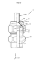
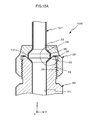
- a connecting pipe 201 formed with a flared portion 201a (diameter-increasing portion) can be connected to the pipe joint 10 of this embodiment.
- the connecting pipe 201 is connected with the pipe joint 10.
- a conventional pipe joint connected with the connecting pipe 201 having already formed with the flared portion 201a is interchangeable with the pipe joint 10 of this embodiment.
- a user can select either one of the pipe joint 10 of this embodiment or the conventional pipe joint as needed.
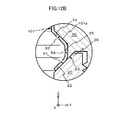
- the pipe joint body 20 has the straight hole face 23 that forms the sealed portion S4.
- the straight hole face 23 can be omitted.
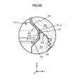
- the three sealed portions S1, S2, and S3 ensure the sealed condition, thereby suitably preventing the coolant from leaking to the exterior of the pipe joint 10A.
- the four sealed portions S1, S2, S3, and S4 ensure the sealed condition.
- the pipe joint body 20 has the straight hole face 23 that forms the sealed portion S4.
- the nut member 30 may have a straight hole face 35.
- the sealed portions S1, S2, and S4 are formed.
- the sealed portion S3 metal seal
- the coolant of the cooling cycle is R32 containing difluoromethane (CH 2 F 2 ).
- the coolant may be HFO1234yf (hydro-floro-olefin) or may be a mixed coolant of R32 and HFO1234yf.
- R32 and HFO1234yf are utilized as an alternative for conventional coolants (for example, R22, and R410A) for the purpose of global warming suppression, but are burnable unlike the conventional coolants.
- R32 and HFO1234yf are utilized as an alternative for conventional coolants (for example, R22, and R410A) for the purpose of global warming suppression, but are burnable unlike the conventional coolants.
- the pipe joint 10 of the embodiments as explained above, an excellent sealing performance is ensured. Hence, when a burnable alternative is utilized, the air conditioner 100 can be safely operated.
- the pipe joint 10 is utilized for a connection between the connecting pipe 101 and the connection port 102a of the indoor equipment 102 of the air conditioner 100, but the present disclosure is not limited to this case.
- the pipe joint can be utilized for a connection between the connecting pipe 101 and the connection port of the outdoor equipment 103.
- the pipe joint 10 is used for the connecting pipe 101 that feeds the coolant of the air conditioner 100, but the present disclosure is not limited to this case.
- the pipe joint is applicable to other pipes than the connecting pipe 101 of the air conditioner 100 as long as such pipes are to feed liquid or gas.
- the pipe joint of the present disclosure is suitable for interconnecting connecting pipes of an air conditioner together.
- the air conditioner of the present disclosure is suitable for air-conditioning of an air-conditioning target.
- the method for producing a connecting pipe according to the present disclosure is suitable to produce the connecting pipe utilized for the air conditioner.
- the connection method of the present disclosure is suitable to connect the pipe joint of the air conditioner with the connecting pipe.
Landscapes
- Engineering & Computer Science (AREA)
- General Engineering & Computer Science (AREA)
- Mechanical Engineering (AREA)
- Joints With Pressure Members (AREA)
- Branch Pipes, Bends, And The Like (AREA)
Applications Claiming Priority (2)
| Application Number | Priority Date | Filing Date | Title |
|---|---|---|---|
| JP2012084258 | 2012-04-02 | ||
| PCT/JP2013/056340 WO2013150858A1 (fr) | 2012-04-02 | 2013-03-07 | Raccord de tube, climatiseur, procédé de production de tube de raccordement, tube de raccordement et procédé de raccordement |
Publications (3)
| Publication Number | Publication Date |
|---|---|
| EP2835568A1 true EP2835568A1 (fr) | 2015-02-11 |
| EP2835568A4 EP2835568A4 (fr) | 2016-01-06 |
| EP2835568B1 EP2835568B1 (fr) | 2019-07-24 |
Family
ID=49023570
Family Applications (1)
| Application Number | Title | Priority Date | Filing Date |
|---|---|---|---|
| EP13772404.3A Active EP2835568B1 (fr) | 2012-04-02 | 2013-03-07 | Raccord de tube raccorde avec un tube et son procede de raccordement |
Country Status (6)
| Country | Link |
|---|---|
| US (1) | US9797532B2 (fr) |
| EP (1) | EP2835568B1 (fr) |
| JP (1) | JP5968427B2 (fr) |
| CN (2) | CN203162387U (fr) |
| AU (1) | AU2013244568B2 (fr) |
| WO (1) | WO2013150858A1 (fr) |
Families Citing this family (19)
| Publication number | Priority date | Publication date | Assignee | Title |
|---|---|---|---|---|
| RU2573864C2 (ru) * | 2011-04-01 | 2016-01-27 | Паркер Ханнифин Мэньюфекчуринг Джемени Гмбх Унд Ко. Кг | Высокопрочное на сжатие резьбовое соединение для трубо-или шлангопроводов с конической резьбой |
| EP2835568B1 (fr) * | 2012-04-02 | 2019-07-24 | Mitsubishi Electric Corporation | Raccord de tube raccorde avec un tube et son procede de raccordement |
| DE102013105300A1 (de) * | 2013-05-23 | 2014-11-27 | Voss Fluid Gmbh | Rohrverbindung |
| JP5891537B2 (ja) * | 2014-07-07 | 2016-03-23 | Smc株式会社 | 管継手 |
| US10060628B2 (en) * | 2015-03-26 | 2018-08-28 | General Electric Company | Systems and methods for creating a seal about a liquid fuel injector in a gas turbine engine |
| GB2539456A (en) * | 2015-06-16 | 2016-12-21 | Woodford Heating & Energy Ltd | A pipe for connection with a pipe fitting |
| DE102015111455A1 (de) * | 2015-07-15 | 2017-01-19 | Esser-Werke Gmbh & Co. Kg | Verfahren zur Herstellung eines Förderrohres für den Feststofftransport sowie Förderrohr für den Feststofftransport |
| SE1551317A1 (en) * | 2015-10-13 | 2017-04-14 | Sapa As | Brake tube connector and brake tube connector assembly |
| US11035509B2 (en) * | 2016-05-19 | 2021-06-15 | Control Flow, Inc. | Metal-to-metal well equipment seal |
| JP6734179B2 (ja) * | 2016-10-31 | 2020-08-05 | 三桜工業株式会社 | 燃料配管 |
| CN107631110B (zh) * | 2017-10-18 | 2023-08-01 | 台州市路桥振兴机械有限公司 | 一种螺母组件及其连接方法 |
| WO2020142710A1 (fr) * | 2019-01-03 | 2020-07-09 | Mega Fluid Systems, Inc. | Dispositifs, ensembles et accouplements d'ajustement d'insert |
| JP7233977B2 (ja) * | 2019-03-07 | 2023-03-07 | 株式会社ブリヂストン | 管継手、配管施工管理システム、及び、配管施工管理方法 |
| WO2021109674A1 (fr) * | 2019-12-04 | 2021-06-10 | 浙江盾安人工环境股份有限公司 | Ensemble écrou anti-démontage et système de climatisation |
| KR102713842B1 (ko) * | 2021-01-25 | 2024-10-10 | 화이트 나이트 플루이드 핸들링 인크. | 튜브 내에 와이어를 밀봉하기 위한 끼워맞춤 |
| KR102374973B1 (ko) * | 2021-09-13 | 2022-03-16 | 주식회사 화영 | 고압 배관의 제조 방법 |
| CN216742873U (zh) * | 2021-12-18 | 2022-06-14 | 浙江盾安人工环境股份有限公司 | 截止阀及其空调机组 |
| DE202022104716U1 (de) * | 2022-08-19 | 2022-09-05 | Ti Automotive Technology Center Gmbh | Verbindungsanordnung |
| WO2026028754A1 (fr) * | 2024-08-01 | 2026-02-05 | 臼井国際産業株式会社 | Matériau de tuyauterie |
Family Cites Families (32)
| Publication number | Priority date | Publication date | Assignee | Title |
|---|---|---|---|---|
| US920963A (en) * | 1906-03-12 | 1909-05-11 | Joseph A Doyle | Pipe-coupling. |
| US1817854A (en) * | 1929-06-11 | 1931-08-04 | Sorensen John | Process of producing coupling flanges |
| US1858136A (en) * | 1931-03-27 | 1932-05-10 | Alphonse Brenner Company Inc | Coupling |
| US1961453A (en) * | 1932-05-25 | 1934-06-05 | Bundy Tubing Co | Tube coupling |
| US2438529A (en) * | 1945-01-25 | 1948-03-30 | George V Woodling | Sleeve nut coupling |
| NL71844C (fr) * | 1945-04-30 | 1900-01-01 | ||
| US2469851A (en) * | 1946-01-18 | 1949-05-10 | Weatherhead Co | Tube coupling |
| US2463883A (en) * | 1946-04-24 | 1949-03-08 | Furlow Cate Mfg Company Inc | Tube coupling |
| US2477677A (en) * | 1947-11-22 | 1949-08-02 | George V Woodling | Turnable coupling member |
| US2545168A (en) * | 1948-10-07 | 1951-03-13 | Brockway Company | Pipe connector |
| US2685461A (en) * | 1949-09-22 | 1954-08-03 | Mueller Co | Pipe coupling |
| US2748463A (en) * | 1949-09-22 | 1956-06-05 | Mueller Co | Method of coupling pipes |
| US2599389A (en) * | 1949-10-17 | 1952-06-03 | Douglas Aircraft Co Inc | Hydraulic fitting |
| JPS5817982Y2 (ja) * | 1978-12-27 | 1983-04-12 | 臼井国際産業株式会社 | 管端部の管継手構造 |
| FR2464424A1 (fr) * | 1979-09-03 | 1981-03-06 | Aerospatiale | Procede pour munir une canalisation d'un embout de raccord et canalisation ainsi obtenue |
| JPH0135027Y2 (fr) * | 1985-01-29 | 1989-10-25 | ||
| US4765661A (en) * | 1985-11-08 | 1988-08-23 | Diesel Kiki Co., Ltd. | Union joint assembly |
| JPS63144827A (ja) * | 1986-12-06 | 1988-06-17 | Masahiro Tokuyama | 鍔付き中空軸の製造方法 |
| DE3701555C1 (de) * | 1987-01-21 | 1988-07-07 | Mannesmann Ag | Rohrverbindung fuer duennwandige,kleinkalibrige Metallrohre |
| CA2086302C (fr) * | 1992-12-24 | 1997-06-03 | Horst Udo Petersen | Machine pour former des brides a l'extremite de tuyaux |
| JP3492503B2 (ja) | 1997-11-11 | 2004-02-03 | 日野自動車株式会社 | 管継手 |
| JPH11218269A (ja) | 1998-02-02 | 1999-08-10 | Toyota Motor Corp | フレア管継手とその表面処理方法 |
| US6089623A (en) | 1998-10-20 | 2000-07-18 | Ford Motor Company | Fluid coupling having stepped synchronized threads |
| US6792782B2 (en) * | 1999-11-30 | 2004-09-21 | Parker Hannifin Sa | Method for deforming a tube near one of its ends and tool used in this method |
| JP2003074768A (ja) | 2001-08-31 | 2003-03-12 | Daikin Ind Ltd | 管継手の構造 |
| CN2562025Y (zh) * | 2002-07-02 | 2003-07-23 | 上海汽车空调配件有限公司 | 一种用于螺纹接头的管材 |
| DE202004012959U1 (de) | 2004-08-18 | 2004-10-14 | Kohlhage Verbindungstechnik Gmbh & Co. Kg | Kugelbuchsenverschraubung |
| CN2934841Y (zh) * | 2006-05-25 | 2007-08-15 | 刘勇 | 空调器室内外机之间新型连接管组件 |
| US8079621B2 (en) * | 2007-11-15 | 2011-12-20 | Lincoln Brass Works, Inc. | Reinforced bead tube design |
| EP2360405A1 (fr) * | 2010-02-19 | 2011-08-24 | TI Automotive (Heidelberg) GmbH | Dispositif de raccordement de tuyaux |
| JP5758640B2 (ja) * | 2011-02-04 | 2015-08-05 | 株式会社フロウエル | チューブ継手 |
| EP2835568B1 (fr) * | 2012-04-02 | 2019-07-24 | Mitsubishi Electric Corporation | Raccord de tube raccorde avec un tube et son procede de raccordement |
-
2013
- 2013-03-07 EP EP13772404.3A patent/EP2835568B1/fr active Active
- 2013-03-07 US US14/373,424 patent/US9797532B2/en not_active Expired - Fee Related
- 2013-03-07 WO PCT/JP2013/056340 patent/WO2013150858A1/fr not_active Ceased
- 2013-03-07 JP JP2014509091A patent/JP5968427B2/ja not_active Expired - Fee Related
- 2013-03-07 AU AU2013244568A patent/AU2013244568B2/en not_active Ceased
- 2013-04-02 CN CN2013201592229U patent/CN203162387U/zh not_active Expired - Lifetime
- 2013-04-02 CN CN201310111934.8A patent/CN103363208B/zh not_active Expired - Fee Related
Also Published As
| Publication number | Publication date |
|---|---|
| JPWO2013150858A1 (ja) | 2015-12-17 |
| AU2013244568B2 (en) | 2016-05-12 |
| US20150008669A1 (en) | 2015-01-08 |
| WO2013150858A1 (fr) | 2013-10-10 |
| JP5968427B2 (ja) | 2016-08-10 |
| US9797532B2 (en) | 2017-10-24 |
| EP2835568A4 (fr) | 2016-01-06 |
| CN203162387U (zh) | 2013-08-28 |
| EP2835568B1 (fr) | 2019-07-24 |
| CN103363208B (zh) | 2016-03-09 |
| AU2013244568A1 (en) | 2014-08-21 |
| CN103363208A (zh) | 2013-10-23 |
Similar Documents
| Publication | Publication Date | Title |
|---|---|---|
| EP2835568A1 (fr) | Raccord de tube, climatiseur, procédé de production de tube de raccordement, tube de raccordement et procédé de raccordement | |
| ES2712807T3 (es) | Racor en particular para tuberías de refrigeración | |
| EP3350497B1 (fr) | Ensemble joint à connexion par pression comprenant un dispositif d'écran de protection et procédé | |
| JP6956773B2 (ja) | 急激な曲げ技術を用いる金属シール嵌め合わせ組立体及びその製造する方法 | |
| US12117111B2 (en) | Swage connector device, assembly and method | |
| JP3939311B2 (ja) | 管継手 | |
| US20210341086A1 (en) | Pipe joint structure and air conditioner | |
| CN112368527B (zh) | 截止阀 | |
| CN112334719B (zh) | 截止阀及其制造方法 | |
| JP2018017293A (ja) | 耐圧型管継手及び耐圧型管継手構造 | |
| JP6867642B2 (ja) | 継手及び該継手へのパイプの接続方法 | |
| JP6549934B2 (ja) | 圧着式管継手装置 | |
| KR200488768Y1 (ko) | 냉매배관용 마킹장치 | |
| CN108526636B (zh) | 减震管及其制造方法 | |
| KR20100099646A (ko) | 에어컨 냉매순환라인의 수놈배관 및 그 제조방법 |
Legal Events
| Date | Code | Title | Description |
|---|---|---|---|
| PUAI | Public reference made under article 153(3) epc to a published international application that has entered the european phase |
Free format text: ORIGINAL CODE: 0009012 |
|
| 17P | Request for examination filed |
Effective date: 20141030 |
|
| AK | Designated contracting states |
Kind code of ref document: A1 Designated state(s): AL AT BE BG CH CY CZ DE DK EE ES FI FR GB GR HR HU IE IS IT LI LT LU LV MC MK MT NL NO PL PT RO RS SE SI SK SM TR |
|
| AX | Request for extension of the european patent |
Extension state: BA ME |
|
| DAX | Request for extension of the european patent (deleted) | ||
| RA4 | Supplementary search report drawn up and despatched (corrected) |
Effective date: 20151203 |
|
| RIC1 | Information provided on ipc code assigned before grant |
Ipc: B21D 39/04 20060101ALI20151127BHEP Ipc: F16L 19/02 20060101AFI20151127BHEP Ipc: F16L 19/028 20060101ALI20151127BHEP Ipc: B21D 17/02 20060101ALI20151127BHEP |
|
| STAA | Information on the status of an ep patent application or granted ep patent |
Free format text: STATUS: EXAMINATION IS IN PROGRESS |
|
| 17Q | First examination report despatched |
Effective date: 20180924 |
|
| GRAP | Despatch of communication of intention to grant a patent |
Free format text: ORIGINAL CODE: EPIDOSNIGR1 |
|
| STAA | Information on the status of an ep patent application or granted ep patent |
Free format text: STATUS: GRANT OF PATENT IS INTENDED |
|
| INTG | Intention to grant announced |
Effective date: 20190211 |
|
| GRAS | Grant fee paid |
Free format text: ORIGINAL CODE: EPIDOSNIGR3 |
|
| GRAA | (expected) grant |
Free format text: ORIGINAL CODE: 0009210 |
|
| STAA | Information on the status of an ep patent application or granted ep patent |
Free format text: STATUS: THE PATENT HAS BEEN GRANTED |
|
| AK | Designated contracting states |
Kind code of ref document: B1 Designated state(s): AL AT BE BG CH CY CZ DE DK EE ES FI FR GB GR HR HU IE IS IT LI LT LU LV MC MK MT NL NO PL PT RO RS SE SI SK SM TR |
|
| REG | Reference to a national code |
Ref country code: GB Ref legal event code: FG4D |
|
| REG | Reference to a national code |
Ref country code: CH Ref legal event code: EP |
|
| REG | Reference to a national code |
Ref country code: DE Ref legal event code: R096 Ref document number: 602013058216 Country of ref document: DE |
|
| REG | Reference to a national code |
Ref country code: AT Ref legal event code: REF Ref document number: 1158598 Country of ref document: AT Kind code of ref document: T Effective date: 20190815 |
|
| REG | Reference to a national code |
Ref country code: IE Ref legal event code: FG4D |
|
| REG | Reference to a national code |
Ref country code: NL Ref legal event code: MP Effective date: 20190724 |
|
| REG | Reference to a national code |
Ref country code: LT Ref legal event code: MG4D |
|
| REG | Reference to a national code |
Ref country code: AT Ref legal event code: MK05 Ref document number: 1158598 Country of ref document: AT Kind code of ref document: T Effective date: 20190724 |
|
| PG25 | Lapsed in a contracting state [announced via postgrant information from national office to epo] |
Ref country code: FI Free format text: LAPSE BECAUSE OF FAILURE TO SUBMIT A TRANSLATION OF THE DESCRIPTION OR TO PAY THE FEE WITHIN THE PRESCRIBED TIME-LIMIT Effective date: 20190724 Ref country code: HR Free format text: LAPSE BECAUSE OF FAILURE TO SUBMIT A TRANSLATION OF THE DESCRIPTION OR TO PAY THE FEE WITHIN THE PRESCRIBED TIME-LIMIT Effective date: 20190724 Ref country code: BG Free format text: LAPSE BECAUSE OF FAILURE TO SUBMIT A TRANSLATION OF THE DESCRIPTION OR TO PAY THE FEE WITHIN THE PRESCRIBED TIME-LIMIT Effective date: 20191024 Ref country code: NL Free format text: LAPSE BECAUSE OF FAILURE TO SUBMIT A TRANSLATION OF THE DESCRIPTION OR TO PAY THE FEE WITHIN THE PRESCRIBED TIME-LIMIT Effective date: 20190724 Ref country code: SE Free format text: LAPSE BECAUSE OF FAILURE TO SUBMIT A TRANSLATION OF THE DESCRIPTION OR TO PAY THE FEE WITHIN THE PRESCRIBED TIME-LIMIT Effective date: 20190724 Ref country code: NO Free format text: LAPSE BECAUSE OF FAILURE TO SUBMIT A TRANSLATION OF THE DESCRIPTION OR TO PAY THE FEE WITHIN THE PRESCRIBED TIME-LIMIT Effective date: 20191024 Ref country code: PT Free format text: LAPSE BECAUSE OF FAILURE TO SUBMIT A TRANSLATION OF THE DESCRIPTION OR TO PAY THE FEE WITHIN THE PRESCRIBED TIME-LIMIT Effective date: 20191125 Ref country code: LT Free format text: LAPSE BECAUSE OF FAILURE TO SUBMIT A TRANSLATION OF THE DESCRIPTION OR TO PAY THE FEE WITHIN THE PRESCRIBED TIME-LIMIT Effective date: 20190724 Ref country code: AT Free format text: LAPSE BECAUSE OF FAILURE TO SUBMIT A TRANSLATION OF THE DESCRIPTION OR TO PAY THE FEE WITHIN THE PRESCRIBED TIME-LIMIT Effective date: 20190724 |
|
| PG25 | Lapsed in a contracting state [announced via postgrant information from national office to epo] |
Ref country code: ES Free format text: LAPSE BECAUSE OF FAILURE TO SUBMIT A TRANSLATION OF THE DESCRIPTION OR TO PAY THE FEE WITHIN THE PRESCRIBED TIME-LIMIT Effective date: 20190724 Ref country code: AL Free format text: LAPSE BECAUSE OF FAILURE TO SUBMIT A TRANSLATION OF THE DESCRIPTION OR TO PAY THE FEE WITHIN THE PRESCRIBED TIME-LIMIT Effective date: 20190724 Ref country code: LV Free format text: LAPSE BECAUSE OF FAILURE TO SUBMIT A TRANSLATION OF THE DESCRIPTION OR TO PAY THE FEE WITHIN THE PRESCRIBED TIME-LIMIT Effective date: 20190724 Ref country code: IS Free format text: LAPSE BECAUSE OF FAILURE TO SUBMIT A TRANSLATION OF THE DESCRIPTION OR TO PAY THE FEE WITHIN THE PRESCRIBED TIME-LIMIT Effective date: 20191124 Ref country code: RS Free format text: LAPSE BECAUSE OF FAILURE TO SUBMIT A TRANSLATION OF THE DESCRIPTION OR TO PAY THE FEE WITHIN THE PRESCRIBED TIME-LIMIT Effective date: 20190724 Ref country code: GR Free format text: LAPSE BECAUSE OF FAILURE TO SUBMIT A TRANSLATION OF THE DESCRIPTION OR TO PAY THE FEE WITHIN THE PRESCRIBED TIME-LIMIT Effective date: 20191025 |
|
| PG25 | Lapsed in a contracting state [announced via postgrant information from national office to epo] |
Ref country code: TR Free format text: LAPSE BECAUSE OF FAILURE TO SUBMIT A TRANSLATION OF THE DESCRIPTION OR TO PAY THE FEE WITHIN THE PRESCRIBED TIME-LIMIT Effective date: 20190724 |
|
| PG25 | Lapsed in a contracting state [announced via postgrant information from national office to epo] |
Ref country code: EE Free format text: LAPSE BECAUSE OF FAILURE TO SUBMIT A TRANSLATION OF THE DESCRIPTION OR TO PAY THE FEE WITHIN THE PRESCRIBED TIME-LIMIT Effective date: 20190724 Ref country code: IT Free format text: LAPSE BECAUSE OF FAILURE TO SUBMIT A TRANSLATION OF THE DESCRIPTION OR TO PAY THE FEE WITHIN THE PRESCRIBED TIME-LIMIT Effective date: 20190724 Ref country code: PL Free format text: LAPSE BECAUSE OF FAILURE TO SUBMIT A TRANSLATION OF THE DESCRIPTION OR TO PAY THE FEE WITHIN THE PRESCRIBED TIME-LIMIT Effective date: 20190724 Ref country code: RO Free format text: LAPSE BECAUSE OF FAILURE TO SUBMIT A TRANSLATION OF THE DESCRIPTION OR TO PAY THE FEE WITHIN THE PRESCRIBED TIME-LIMIT Effective date: 20190724 Ref country code: DK Free format text: LAPSE BECAUSE OF FAILURE TO SUBMIT A TRANSLATION OF THE DESCRIPTION OR TO PAY THE FEE WITHIN THE PRESCRIBED TIME-LIMIT Effective date: 20190724 |
|
| PG25 | Lapsed in a contracting state [announced via postgrant information from national office to epo] |
Ref country code: CZ Free format text: LAPSE BECAUSE OF FAILURE TO SUBMIT A TRANSLATION OF THE DESCRIPTION OR TO PAY THE FEE WITHIN THE PRESCRIBED TIME-LIMIT Effective date: 20190724 Ref country code: SK Free format text: LAPSE BECAUSE OF FAILURE TO SUBMIT A TRANSLATION OF THE DESCRIPTION OR TO PAY THE FEE WITHIN THE PRESCRIBED TIME-LIMIT Effective date: 20190724 Ref country code: SM Free format text: LAPSE BECAUSE OF FAILURE TO SUBMIT A TRANSLATION OF THE DESCRIPTION OR TO PAY THE FEE WITHIN THE PRESCRIBED TIME-LIMIT Effective date: 20190724 Ref country code: IS Free format text: LAPSE BECAUSE OF FAILURE TO SUBMIT A TRANSLATION OF THE DESCRIPTION OR TO PAY THE FEE WITHIN THE PRESCRIBED TIME-LIMIT Effective date: 20200224 |
|
| REG | Reference to a national code |
Ref country code: DE Ref legal event code: R097 Ref document number: 602013058216 Country of ref document: DE |
|
| PLBE | No opposition filed within time limit |
Free format text: ORIGINAL CODE: 0009261 |
|
| STAA | Information on the status of an ep patent application or granted ep patent |
Free format text: STATUS: NO OPPOSITION FILED WITHIN TIME LIMIT |
|
| PG2D | Information on lapse in contracting state deleted |
Ref country code: IS |
|
| 26N | No opposition filed |
Effective date: 20200603 |
|
| PG25 | Lapsed in a contracting state [announced via postgrant information from national office to epo] |
Ref country code: SI Free format text: LAPSE BECAUSE OF FAILURE TO SUBMIT A TRANSLATION OF THE DESCRIPTION OR TO PAY THE FEE WITHIN THE PRESCRIBED TIME-LIMIT Effective date: 20190724 |
|
| PG25 | Lapsed in a contracting state [announced via postgrant information from national office to epo] |
Ref country code: MC Free format text: LAPSE BECAUSE OF FAILURE TO SUBMIT A TRANSLATION OF THE DESCRIPTION OR TO PAY THE FEE WITHIN THE PRESCRIBED TIME-LIMIT Effective date: 20190724 |
|
| REG | Reference to a national code |
Ref country code: CH Ref legal event code: PL |
|
| REG | Reference to a national code |
Ref country code: BE Ref legal event code: MM Effective date: 20200331 |
|
| PG25 | Lapsed in a contracting state [announced via postgrant information from national office to epo] |
Ref country code: LU Free format text: LAPSE BECAUSE OF NON-PAYMENT OF DUE FEES Effective date: 20200307 |
|
| PG25 | Lapsed in a contracting state [announced via postgrant information from national office to epo] |
Ref country code: FR Free format text: LAPSE BECAUSE OF NON-PAYMENT OF DUE FEES Effective date: 20200331 Ref country code: IE Free format text: LAPSE BECAUSE OF NON-PAYMENT OF DUE FEES Effective date: 20200307 Ref country code: CH Free format text: LAPSE BECAUSE OF NON-PAYMENT OF DUE FEES Effective date: 20200331 Ref country code: LI Free format text: LAPSE BECAUSE OF NON-PAYMENT OF DUE FEES Effective date: 20200331 |
|
| PG25 | Lapsed in a contracting state [announced via postgrant information from national office to epo] |
Ref country code: BE Free format text: LAPSE BECAUSE OF NON-PAYMENT OF DUE FEES Effective date: 20200331 |
|
| GBPC | Gb: european patent ceased through non-payment of renewal fee |
Effective date: 20200307 |
|
| PG25 | Lapsed in a contracting state [announced via postgrant information from national office to epo] |
Ref country code: GB Free format text: LAPSE BECAUSE OF NON-PAYMENT OF DUE FEES Effective date: 20200307 |
|
| PG25 | Lapsed in a contracting state [announced via postgrant information from national office to epo] |
Ref country code: MT Free format text: LAPSE BECAUSE OF FAILURE TO SUBMIT A TRANSLATION OF THE DESCRIPTION OR TO PAY THE FEE WITHIN THE PRESCRIBED TIME-LIMIT Effective date: 20190724 Ref country code: CY Free format text: LAPSE BECAUSE OF FAILURE TO SUBMIT A TRANSLATION OF THE DESCRIPTION OR TO PAY THE FEE WITHIN THE PRESCRIBED TIME-LIMIT Effective date: 20190724 |
|
| PG25 | Lapsed in a contracting state [announced via postgrant information from national office to epo] |
Ref country code: MK Free format text: LAPSE BECAUSE OF FAILURE TO SUBMIT A TRANSLATION OF THE DESCRIPTION OR TO PAY THE FEE WITHIN THE PRESCRIBED TIME-LIMIT Effective date: 20190724 |
|
| P01 | Opt-out of the competence of the unified patent court (upc) registered |
Effective date: 20230512 |
|
| PGFP | Annual fee paid to national office [announced via postgrant information from national office to epo] |
Ref country code: DE Payment date: 20240130 Year of fee payment: 12 |
|
| REG | Reference to a national code |
Ref country code: DE Ref legal event code: R119 Ref document number: 602013058216 Country of ref document: DE |
|
| PG25 | Lapsed in a contracting state [announced via postgrant information from national office to epo] |
Ref country code: DE Free format text: LAPSE BECAUSE OF NON-PAYMENT OF DUE FEES Effective date: 20251001 |