EP3350497B1 - Ensemble joint à connexion par pression comprenant un dispositif d'écran de protection et procédé - Google Patents
Ensemble joint à connexion par pression comprenant un dispositif d'écran de protection et procédé Download PDFInfo
- Publication number
- EP3350497B1 EP3350497B1 EP16847278.5A EP16847278A EP3350497B1 EP 3350497 B1 EP3350497 B1 EP 3350497B1 EP 16847278 A EP16847278 A EP 16847278A EP 3350497 B1 EP3350497 B1 EP 3350497B1
- Authority
- EP
- European Patent Office
- Prior art keywords
- wall
- compartment
- axially
- fastening ring
- ring
- Prior art date
- Legal status (The legal status is an assumption and is not a legal conclusion. Google has not performed a legal analysis and makes no representation as to the accuracy of the status listed.)
- Active
Links
Images




Classifications
-
- F—MECHANICAL ENGINEERING; LIGHTING; HEATING; WEAPONS; BLASTING
- F16—ENGINEERING ELEMENTS AND UNITS; GENERAL MEASURES FOR PRODUCING AND MAINTAINING EFFECTIVE FUNCTIONING OF MACHINES OR INSTALLATIONS; THERMAL INSULATION IN GENERAL
- F16L—PIPES; JOINTS OR FITTINGS FOR PIPES; SUPPORTS FOR PIPES, CABLES OR PROTECTIVE TUBING; MEANS FOR THERMAL INSULATION IN GENERAL
- F16L37/00—Couplings of the quick-acting type
- F16L37/26—Couplings of the quick-acting type in which the connection is made by transversely moving the parts together, with or without their subsequent rotation
-
- F—MECHANICAL ENGINEERING; LIGHTING; HEATING; WEAPONS; BLASTING
- F16—ENGINEERING ELEMENTS AND UNITS; GENERAL MEASURES FOR PRODUCING AND MAINTAINING EFFECTIVE FUNCTIONING OF MACHINES OR INSTALLATIONS; THERMAL INSULATION IN GENERAL
- F16L—PIPES; JOINTS OR FITTINGS FOR PIPES; SUPPORTS FOR PIPES, CABLES OR PROTECTIVE TUBING; MEANS FOR THERMAL INSULATION IN GENERAL
- F16L37/00—Couplings of the quick-acting type
- F16L37/08—Couplings of the quick-acting type in which the connection between abutting or axially overlapping ends is maintained by locking members
- F16L37/084—Couplings of the quick-acting type in which the connection between abutting or axially overlapping ends is maintained by locking members combined with automatic locking
- F16L37/091—Couplings of the quick-acting type in which the connection between abutting or axially overlapping ends is maintained by locking members combined with automatic locking by means of a ring provided with teeth or fingers
- F16L37/0915—Couplings of the quick-acting type in which the connection between abutting or axially overlapping ends is maintained by locking members combined with automatic locking by means of a ring provided with teeth or fingers with a separate member for releasing the coupling
-
- F—MECHANICAL ENGINEERING; LIGHTING; HEATING; WEAPONS; BLASTING
- F16—ENGINEERING ELEMENTS AND UNITS; GENERAL MEASURES FOR PRODUCING AND MAINTAINING EFFECTIVE FUNCTIONING OF MACHINES OR INSTALLATIONS; THERMAL INSULATION IN GENERAL
- F16L—PIPES; JOINTS OR FITTINGS FOR PIPES; SUPPORTS FOR PIPES, CABLES OR PROTECTIVE TUBING; MEANS FOR THERMAL INSULATION IN GENERAL
- F16L25/00—Construction or details of pipe joints not provided for in, or of interest apart from, groups F16L13/00 - F16L23/00
- F16L25/0018—Abutment joints
-
- F—MECHANICAL ENGINEERING; LIGHTING; HEATING; WEAPONS; BLASTING
- F16—ENGINEERING ELEMENTS AND UNITS; GENERAL MEASURES FOR PRODUCING AND MAINTAINING EFFECTIVE FUNCTIONING OF MACHINES OR INSTALLATIONS; THERMAL INSULATION IN GENERAL
- F16L—PIPES; JOINTS OR FITTINGS FOR PIPES; SUPPORTS FOR PIPES, CABLES OR PROTECTIVE TUBING; MEANS FOR THERMAL INSULATION IN GENERAL
- F16L58/00—Protection of pipes or pipe fittings against corrosion or incrustation
- F16L58/18—Protection of pipes or pipe fittings against corrosion or incrustation specially adapted for pipe fittings
Definitions
- the present invention relates to fluid flow systems, and more particularly to a push-fit joint assembly, device and method that facilitates the simple connection, disconnection, repair and re-use of piping and tubing system parts without coining or threaded end caps.
- Piping systems exist to facilitate the flow of fluids (e.g., liquid, gas (such as air) or plasma).
- fluids e.g., liquid, gas (such as air) or plasma
- homes, schools, medical facilities, commercial buildings and other occupied structures generally require integrated piping systems so that water and/or other fluids can be circulated for a variety of uses.
- Liquids and/or gases such as cold and hot water, breathable air, glycol, compressed air, inert gases, cleaning chemicals, waste water, plant cooling water and paint and coatings are just some examples of the types of fluids and gases that can be deployed through piping systems.
- Tubing and piping types can include, for example, copper, stainless steel, CPVC (chlorinated polyvinyl chloride) and PEX (cross-linked polyethylene).
- the term "pipe” or "piping” will be understood to encompass one or more pipes, tubes, piping elements and/or tubing elements.
- Piping connections are necessary to join various pieces of pipe and must be versatile in order to adapt to changes of pipe direction required in particular piping system implementations.
- fittings and valves may be employed at the ends of open pieces of pipe that enable two pieces of pipe to fit together in a particular configuration.
- fitting types there are elbows, "tees", couplings adapted for various purposes such as pipe size changes, ends, ball valves, stop valves, and partial angle connectors, for example.
- soldering pipe fittings can be time-consuming, unsafe, and labor intensive. Soldering also requires employing numerous materials, such as copper pipes and fittings, emery cloths or pipe-cleaning brushes, flux, silver solder, a soldering torch and striker, a tubing cutter and safety glasses, for example.
- the process for soldering pipes can proceed by first preparing the pipe to be soldered, as the copper surface must be clean in order to form a good joint. The end of the pipe can be cleaned on the outside with emery cloth or a specially made wire brush. The inside of the fitting must be cleaned as well.
- flux (a type of paste) can be applied to remove oxides and draw molten solder into the joint where the surfaces will be joined.
- the brush can be used to coat the inside of the fitting and the outside of the pipe with the flux.
- the two pipes are pushed together firmly into place so that they "bottom out"--i.e., meet flush inside the fitting.
- the tip of the solder can be bent to the size of the pipe in order to avoid over-soldering.
- the torch is then ignited with the striker or by an auto-strike mechanism to initiate soldering. After heating for a few moments, if the copper surface is hot enough such that it melts when touched by the end of the solder, the solder can then be applied to the joint seam so that it runs around the joint and bonds the pipe and fitting together.
- Push-fit technology has been employed with piping systems to reduce the dangers and time involved in soldering joints.
- Push-fit methods require minimal knowledge of pipe fittings and involve far fewer materials than soldering. For example, one may only need the pipes, quick-connect fittings, a chamfer/de-burring tool and tubing cutter in order to connect pipes using push-fit technology.
- the steps involved in connecting piping systems using push-fit technology can be outlined as follows. First, the pipe is cut to the appropriate length and the end of the pipe is cleaned with the de-burring tool. Then the pipe and fitting are pushed together for connection.
- the fitting is provided with a fastening ring (also called a collet, grip ring or grab ring) having teeth that grip the pipe as it is inserted.
- the fastening ring device is employed to provide opposing energy, preventing the device from disconnection while creating a positive seal. Accordingly, no wrenches, clamping, gluing or soldering is involved.
- Push-fit and/or quick-connect technology for piping systems can be obtained, for example, through Quick Fitting, Inc.
- the fastening ring is inserted into the fitting body along with a plastic grip ring support that typically fails under extensive tensile testing. Further, the coupling must then be either coin rolled, glued or receive a threaded cap member to retain the fastening ring inside the fitting body. In addition to the added steps for the manufacture and assembly of the coupling, the strength of the plumbing joint is determined by the retaining cap member. The additional steps and components add significant labor and manufacturing costs to the final product cost and reduce the overall production capability due to the extensive time required for proper assembly.
- the process of cutting threads into the fitting body and the retaining cap elevates the cost of machining the fitting components.
- the threaded end cap method requires mechanical assembly as well as the added cost and application of a thread sealant to the threads.
- the process of coining the fitting body as the retaining cap significantly increases the cost of final assembly of the fitting.
- the coining process permanently encapsulates the fastening ring inside the fitting, whereby the fastening ring cannot be removed without complete destruction of the ring and fitting.
- the document CN 202501139 U discloses a dismountable push-to-connect joint assembly.
- Past methods further invariably require the replacement of fittings and valves, and do not allow re-use of the fittings or valves in instances where only a small internal component needs to be repaired or replaced. Further, past products and methods do not provide enhanced protective retainers among various packing components such that, in the event of degrading or catastrophic failure of internal parts, such parts would be precluded from separating or moving out of the fitting.
- the present invention provides, in part, a push fitting assembly package that facilitates the re-use of push fittings without damage to the fitting elements or the pipe.
- the present invention connects piping using no tools, clamps, solder or glues, while creating a leak-free seal at the connected joining area. Further, the present invention can join both like and unlike piping elements without coining or threading the elements into place.
- the present invention also provides a protective retainer on various packing components such that, in the event of degrading or catastrophic failure of internal parts, such parts would be precluded from separating. As described, various embodiments of the present invention can withstand up to 3600 pounds of pressure or more, and are thus employable within a heating, ventilation and air-conditioning (HVAC) environment.
- HVAC heating, ventilation and air-conditioning
- the quick connection pipe joint assembly package provided as part of the present invention employs a release pusher member that, when removed, exposes the clamping, sealing and fastening mechanisms of the fitting.
- the release pusher member also called the "release pusher” moves axially and can push the fastening ring of the present invention in order to facilitate the release of a cylindrical object such as a piping element held within the fitting.
- a fitting (also referred to as a body member) can encompass a valve member and other piping elements including, but not limited to: a coupling joint, an elbow joint, a tee joint, a stop end, a ball valve member, tubing and other objects having cylindrical openings.
- one or more sealing member gasket inserts e.g., O-ring members
- a fastening ring support compartment is machined into the interior wall to retain at least a portion of the body of the fastening ring.
- the interior housing elements provide integrated support for the sealing member(s) and fastening ring when opposing force is applied to piping elements that have been inserted into the fitting.
- a retaining ring and shield member are employed within a retaining ring support compartment machined into the interior wall of the fitting to provide additional support for the fastening ring and to cooperate with the release pusher to facilitate connection and disconnection of piping elements.
- the invention consists in a push fitting joint packing arrangement comprising a sealing ring member, a fastening ring, a fastening ring support member, a shield member, a retaining ring member and a release pusher member.
- the shield member provided as part of the present invention can be configured so as to be slidable into the fitting and snapped into place during installation prior to the retaining ring member.
- the shield member can be provided with flat or substantially flat sides to drop into position at an angle other than perpendicular to the central axis of the fitting. No coining is necessary in order to insert the shield member.
- the release pusher provided as part of the present invention is employed to facilitate the release of tubing, piping and other cylindrical objects inserted into a fitting.
- the release pusher is manually pushed into the cavity formed by the tube support member within the fitting body and tapered edges of the release pusher generally or nearly abut the installed fastening ring.
- the release pusher can be forced in the direction of the fastening ring such that its angular surfaces depress the fastening ring teeth off of the surface of the inserted pipe, thereby allowing the pipe to be removed.
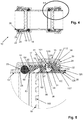
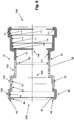
- elements of the joint assembly as shown include: a fitting (i.e., fitting body member) 12 having an inner wall 13 and an outer wall 15.
- the inner wall 13 forms a cavity 150 extending along a central axis 11 that extends axially through the fitting.
- the respective diameters of the inner wall 13 and outer wall 15 as measured from the central axis 11 increase from an axially inner segment 21 of the fitting to the axial mid-segment 23 of the fitting, and from the axial mid-segment 23 of the fitting to the axially outer segment 25 of the fitting.
- the fitting 12 includes a first interior wall portion 191 separated from a second interior wall portion 192 by tube stop 33. At least the first interior wall portion 191 is formed so as to include a sealing ring compartment 41, a fastening ring compartment 42 and a retaining ring compartment 43.
- the compartments 41, 42 and 43, as well as tube stop 33 are formed as part of the inner surface of the fitting 12 through hydroforming or similar methods. In this way, internal compartments within the fitting 12 are sized so as to receive packing arrangement elements as described herein, and the fitting with compartments and tube stop comprises a monolithic, integrated structure.
- retaining ring compartment 43 comprises a front wall portion 130, a back wall portion 132 and a first linear segment 133 of the inner wall 13.
- the back wall portion 132 can have an interior face 150, a radially inner wall 44 and an exterior face 45.
- the radially inner wall 44 is not parallel with the axis 11, but rather extends radially outwardly from an axially inner edge 47 to an axially outer edge 48. In this way, packing arrangement components to be inserted into the fitting need not be perfectly and/or perpendicularly aligned with the radially inner wall 44, but rather can meet the back wall portion 132 at different angles while still being manipulable into the fitting opening.
- the radially inner wall 44 thus facilitates ease of insertion and removal of packing arrangement components without coining.
- fastening ring compartment 42 can comprise a second linear segment 135 extending from the front wall portion 130 of retaining ring compartment 43 to a riser segment 137 of the inner wall 13
- sealing ring compartment 41 can comprise a third linear segment 139 extending from the riser segment 137 to a sealing ring stop wall 140 of the inner wall 13.
- the inner wall 13 of the fitting 12 can also include an axially inner segment 142 extending from the sealing ring stop wall 140 to the tube stop 33.
- the compartments 41, 42 and 43 and the elements comprising the compartments can be provided in both the first 191 and the second 192 interior wall portions of the fitting 12, and can be substantially mirror images of one another. As further shown in Fig.
- the axially inner segment 21 of the fitting 12 encompasses the axially inner segment 142 of the inner wall 13
- the axial mid-segment 23 of the fitting 12 encompasses the sealing ring compartment 41 and the fastening ring compartment 42
- the axially outer segment 25 of the fitting 12 encompasses the retaining ring compartment 43.
- the fitting external wall 15 has an axially internal portion 152, an axial mid-portion 154 and an axially outer portion 156.
- the axially internal portion 152 has a first radial distance from the axis 11, the axial mid-portion 154 has a second radial distance from the axis 11, and the axially outer portion 156 has a third radial distance from the axis 11, wherein the third radial distance is larger than either of the first and second radial distances, and the second radial distance is larger than the first radial distance.
- the fitting 12 maintains a profile and structure that permits it to house the elements of the packing arrangement as described herein, while retaining significant strength to withstand up to 3600 pounds of pressure or more.
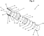
- the packing arrangement of the present invention comprises: at least one sealing ring member 14 (which can be optionally lubricated), a sealing ring support member 17, a fastening ring 18, a fastening ring support member 20, a shield member 22, a retaining ring member 24 and a release pusher 26.
- the fastening ring 18, sealing member 14, sealing ring support member 17 and release pusher 26 each have an internal diameter that allows for smooth and snug engagement of a piping or tubing element external surface (not shown), whereas the shield member 22 and retaining ring member 24 do not contact any piping or tubing element inserted into or removed from the fitting.
- the release pusher 24 does not contact fitting inner wall 13 during operation.
- the fitting 12 is substantially hollow, in the sense that the inner wall 13 defines a pipe receiving opening 30 extending axially therethrough.
- the fitting 12 can be forged CW617N brass, with full porting and full flow fitting, for example.
- the inner wall 13 of the fitting 12 includes an internal stop 33 extending radially inwardly from the inner wall 13 so as to provide a circumferential resistance to tubes inserted on either side of the fitting.
- the lubricant for the one or more sealing members 14 can be a food grade lubricant, for example. It will be appreciated that the sealing members can comprise a flat ring or washer-type seal member in addition or as an alternative to a circular member of substantially circular cross-section.
- the fastening ring 18 can comprise a spring steel formulation, for example, that enables the fastening ring to be malformed during installation, while springing back into its originally manufactured position once installed.
- the fastening ring is capable of grabbing an inserted pipe's surface via two or more teeth 19 to ensure connections cannot be pulled apart.
- the fastening ring teeth 19 are angled downward from the substantially cylindrical perimeter or base 70 of the ring, toward the tube stop 33 and away from the retaining ring compartment 43, such that when the pipe is inserted, the teeth exert a pressure against the pipe to discourage the pipe from slipping or moving back out of the fitting. No wrenches, solder, welding, glue and/or twisting and turning the elements are required to form a connection.
- the combination of the sealing ring 14, fastening ring 18, shield member 22 and retaining ring member 24 provide a push-fit piping assembly when inserted into any cylindrical pipe in accordance with the present invention.
- one or more sealing members 14 is of sufficient size to firmly fit within the sealing ring compartment 41 and against third linear wall 139 of the inner wall 13 of the fitting.
- Fastening ring 18 includes a base portion 70 and a plurality of bifurcated or square edged teeth 19 extending inwardly from and along the base 70, wherein the base portion 70 is of sufficient diameter to firmly fit within the fastening ring compartment 42 and against second linear segment 135 of the inner wall 13 when the device is assembled.
- the sealing ring support member 17 includes an axially inner wall 60 and an axially outer wall 62, wherein the sealing ring support member 17 is positioned at least partially within the sealing ring compartment 41 and at least partially within the fastening ring support compartment 42, and further wherein the sealing ring support member axially inner wall 60 is adapted to be in mating contact with the sealing ring 14.
- the axially inner wall 60 can be formed with an axially extending rampart base 64 and a rampart wall 65 extending radially outwardly of the rampart base 64.
- the rampart base 64 can engage the third linear segment 139 of the inner wall 13 and rampart wall 65 can engage the riser segment 137 of the inner wall 13 to provide stable support for the axial pressures received by the support member 17 during operation.
- the radially interior edge 63 of the sealing ring support member 17 can engage an inserted pipe during operation, and assists in guiding a pipe over the sealing ring 14 for proper alignment.
- the radially inner wall 69 of support member 17 is angled so as to permit flexing of the fastening ring teeth 19 to a limited degree as the release pusher moves the teeth 19 axially inwardly during operation to facilitate insertion or removal of a piping element.
- the base portion 70 of the fastening ring 18 has a front wall 72, a rear wall 73 and a radially outer edge 74.
- the base portion 70 is positioned within the fastening ring support compartment 42 such that the outer edge 74 engages the second linear segment 135, and such that the front wall 72 is in mating contact with the axially outer wall 62 of the sealing ring support member 17.
- the fastening ring support member 20 can include a first axial wall 80, a second axial wall 82 and a radially outer wall 83, wherein the fastening ring support member is positioned within the fastening ring support compartment such that the radially outer wall 83 engages the second linear segment 135 of the inner wall 13 of the fitting, and such that the first axial wall 80 of the fastening ring support member 20 is in mating contact with the rear wall 73 of the fastening ring 18.
- the fastening ring base 70 is securely maintained between the first axial wall 80 of the fastening ring support member 20 and the axially outer wall 62 of the sealing ring support member 17.
- the support member 20 includes a radially inner surface 86, a beveled back edge 85 extending from the second axial wall 82 to the inner surface 86, and an angled front edge 87 extending from the first axial wall 80 to the inner surface 86.
- the angled front edge 87 provides at least partial support to the back edges 165 of the fastening ring teeth 19 during operation.
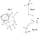
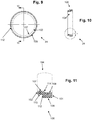
- the shield member 22 comprises a body having inner 90 and outer 92 faces, an inner edge surface 93 and an outer edge surface 94, wherein the inner edge surface 93 is substantially cylindrical, and the outer edge surface 94 is not cylindrical.
- the outer edge surface 94 is formed with at least two parallel, diametrically opposed edge segments 95 and further is formed with at least two non-parallel, diametrically opposed edge segments 96.
- each of the parallel edge segments 95 has a width W1
- each of the non-parallel edge segments 96 has a width W2, where W2 is greater than W1.
- the shield member 22 can slide through the opening 200 created by the back wall portion 132 of the retaining ring compartment 43 before the retaining ring 24 is snapped into place.
- the parallel edge segments 95 can be aligned with the interior edge 47 defining the fitting opening 200 so as to be insertable without coining. Once inserted, the edge segments 96 of the shield member outer edge surface 94 are in mating contact with the first linear segment 133 of the retaining ring compartment 43, whereas the edge segments 95 are not.
- a first portion 97 of the inner face 90 of the shield member is in mating contact with the front wall portion 130 of the retaining ring compartment 43, and a second portion 98 of the shield member inner face 90 is not in mating contact with the retaining ring compartment, but is rather in contact with the second axial wall 82 of the fastening ring support member 20.
- the outer face 92 of the shield member 22 is in mating contact with an axially internal wall 101 of the retaining ring member 24, once the retaining ring member is installed.
- the retaining ring member 24 has an axially internal wall 101, an axially external wall 102, a radially internal wall 104, and a radially external wall 106.
- the axially external wall 102 extends from an overhang surface 110 to a ledge surface 107 of the radially internal wall 104.
- a radially extending mid-wall 112 extends from the overhang surface 110 to a radially outer portion 109 of the radially external wall 106.
- a radially extending side wall 114 extends from the ledge surface 107 of the radially internal wall 104 to a platform surface 108 of the radially internal wall 104.
- the ledge surface 107 of the radially internal wall 104 acts as guide for the outer surface 126 of the release pusher 26.
- the side wall 114 acts as a retainer for the annular retaining edge 31 of the release pusher 26.
- the edge 31 can slide along the platform surface 108 of the retaining ring member 24 when the release pusher 26 is pushed axially inwardly to engage the fastening ring teeth 19.
- the radially extending mid-wall 112 engages the back wall portion 132 of the inner wall 13 of the fitting 12, while the radially outer portion 109 of the radially external wall 106 is in mating contact with the first linear segment 133 of the inner wall.
- the axially internal wall 101 engages the shield member 22 as described above.
- the release pusher 26 is substantially cylindrical, includes an external tip 29 at the fastening ring engaging end 160 thereof, and further includes an annular retaining edge 31 extending radially outwardly of an outer wall 126, 128 of the release pusher 26.
- the outer wall portion 128 that extends axially inwardly into the fitting 12 during operation can have an external radius that is smaller than the external radius of the outer wall portion 126 of the pusher, which facilitates the sliding contact between outer wall portion 128 and fastening ring support member 20, as well as the sliding contact between outer wall portion 126 and retaining ring member 24 during operation. As shown in Fig.
- the release pusher retaining edge 31 can include a radial outer ledge 124, a front wall 127 and a back wall 130.
- Shield member 22 can be designed and positioned such that it does not contact outer wall portion 128 of the release pusher 26 during operation, so as to minimize any resisting force on the operation of the release pusher.
- the shield member 22 inner edge 93 can extend to the outer wall 128 of the release pusher 26.
- the release pusher 26 can comprise an injection-molded plastic material or a metal material such as brass, for example.
- the external tip 29 can engage the inside surface 165 of the fastening ring teeth 19, and the edge back wall 130 can removeably engage a retaining lip 114 extending radially inwardly from the radially internal wall 104 of retaining ring 24, as shown in Fig. 5 .
- the fastening ring 18 can be a split ring member or can be an integral member with no split.
- a split can facilitate insertion and/or removal, by allowing the diameter of the base 18 to be slightly reduced through pressure so that the fastening ring can be more readily manipulable.
- the fastening ring support member can also be split.
- the shield member 22 can be provided with teeth on the inner edge 93 thereof to act as a secondary fastening ring.
- the sealing ring support member 17 and/or the fastening ring support member 20 can be integrally formed into the inner wall 13 of the fitting, thereby becoming a unitary, monolithic structure with the fitting.
- the fitting 12 of the present invention is provided and one or more sealing members (e.g., 14) are inserted into the sealing ring compartment 41.
- a sealing ring support member 17 is inserted so as to extend into the sealing ring compartment adjacent the sealing ring 14. It will be appreciated that a portion of the sealing ring support member 17 will also lie in the fastening ring compartment 42, as described above, and shown, for example, in Figs. 4 and 5 .
- the fastening ring 18 is then inserted into the fastening ring support compartment 42, followed by the fastening ring support member 20.
- the shield member 22 is inserted without any coining or threaded connection adjacent the fastening ring support member, and the retaining ring 24 is then inserted into the retaining ring compartment so as to abut the shield member 22 as described above.
- the release pusher 26 is then snapped into engagement with the inner surface 104 of the retaining ring member 24.
- a pipe (not shown) is inserted, it travels through the release pusher 26 into the pipe receiving cavity 200 of the fitting 12, engaging the fastening ring 18 and the one or more sealing members 14.
- the sealing members provide a strong, leak-free seal and the fastening ring prohibits any inclination the pipe may have to slide out of position.
Landscapes
- Engineering & Computer Science (AREA)
- General Engineering & Computer Science (AREA)
- Mechanical Engineering (AREA)
- Quick-Acting Or Multi-Walled Pipe Joints (AREA)
Claims (10)
- Ensemble joint instantané (10), comprenant :un raccord monolithique (12) ayant une paroi intérieure (13) et une paroi extérieure (15), la paroi intérieure (13) délimitant une cavité (150) s'étendant axialement au travers du raccord (12) et comprenant une première partie de paroi intérieure (191) comprenant une pluralité de compartiments en creux espacés axialement délimitant un compartiment de bague d'étanchéité (41), un compartiment de support de bague d'étanchéité (42) et un compartiment de bague de tenue (43) ;une première bague d'étanchéité (14) positionnée dans le compartiment de bague d'étanchéité (41) ;un élément support de bague d'étanchéité (17) ayant une paroi intérieure axiale (60) et une paroi extérieure axiale (62), l'élément support de bague d'étanchéité (17) étant positionné au moins à certains endroits à l'intérieur du compartiment de bague d'étanchéité (41) et au moins à certains endroits à l'intérieur du compartiment de support de bague de fixation (42), la paroi intérieure axiale (60) de l'élément support de bague d'étanchéité (60) étant conçue pour être en contact complémentaire avec la première bague d'étanchéité (14) ;une bague de fixation (18) ayant une partie base (70), la partie base (70) ayant une paroi avant (72), une paroi arrière (73) et un bord extérieur radial (74), la partie base (70) étant positionné à l'intérieur du compartiment de support de la bague de fixation (42) et la paroi avant (72) étant en contact complémentaire avec la paroi extérieure axiale (62) de l'élément de support de bague d'étanchéité (17) ;un élément de support de bague de fixation (20) ayant une première paroi axiale (80), une seconde paroi axiale (82) et une paroi extérieure radiale (83), l'élément de support de la bague de fixation (20) étant positionné à l'intérieur du compartiment de support de bague de fixation (42) et la première paroi axiale (80) de l'élément de support de bague de fixation (20) étant en contact complémentaire avec la paroi arrière (73) de la bague de fixation (18) ;un élément de protection (22) ayant des première (90) et seconde (92) faces, une surface de bord intérieur (93) et une surface de bord extérieur (94), l'élément de protection (22) étant positionné à l'intérieur du compartiment de bague de retenue (43) et la première face (90) étant en contact complémentaire avec la seconde paroi axiale (82) de l'élément de support de bague de fixation (20) ;un élément de bague de retenue (24) ayant une paroi intérieure axiale (101), une paroi extérieure axiale (102), une paroi intérieure radiale (104), et une paroi extérieure radiale (106), l'élément de bague de retenue (24) étant positionné à l'intérieur du compartiment de bague de retenue (43) et la paroi intérieure axiale (101) de l'élément de bague de retenue (24) étant en contact complémentaire avec la seconde face (92) de l'élément de protection (22) ; etun élément de poussoir de desserrage (26) inséré à coulissement dans la paroi interne radiale (104) de la bague de retenue.
- Ensemble selon la revendication 1, la première face (90) de l'élément de protection ayant une première partie (97) et une seconde partie (98), et la première partie (97) de la première face (90) de l'élément de protection étant en contact complémentaire avec le compartiment de la bague de retenue (43), et la seconde partie (98) de la première face (90) de l'élément de protection étant en contact avec l'élément de support (20) de la bague de fixation.
- Ensemble selon la revendication 1, la surface de bord intérieur de l'élément de protection (93) étant sensiblement cylindrique, et la surface de bord extérieur de l'élément de protection (94) n'étant pas cylindrique.
- Ensemble selon la revendication 1, la surface de bord extérieur (94) de l'élément de protection (22) étant constituée d'au moins deux segments marginaux diamétralement opposés, parallèles (95) et étant en outre constitué d'au moins deux segments marginaux diamétralement opposés, non-parallèles (96), les segments marginaux non-parallèles (96) étant en contact complémentaire avec le compartiment de bague de retenue (43), et les segments marginaux parallèles (95) n'étant pas en contact complémentaire avec le compartiment de bague de retenue (43).
- Ensemble selon la revendication 4, chacun des segments marginaux (95) qui n'est pas en contact complémentaire avec le compartiment de bague de retenue (43) ayant une largeur W1, et chacun des segments marginaux (96) qui est en contact complémentaire avec le compartiment de bague de retenue (43) ayant une largeur W2, et en outre, W2 étant supérieure à W1.
- Ensemble selon la revendication 4, le poussoir de desserrage (26) étant positionné radialement à l'intérieur de l'élément de bague de retenue (24) à l'intérieur du raccord (12).
- Ensemble selon la revendication 6, comprenant en outre une seconde bague d'étanchéité positionnée à l'intérieur du compartiment de bague d'étanchéité (41).
- Ensemble selon la revendication 7, l'élément de support de bague de fixation (20) et/ou la bague de fixation (18) étant séparé.
- Ensemble selon la revendication 1, l'élément poussoir de desserrage (26) n'étant pas en contact avec le raccord (12).
- Procédé d'assemblage d'un ensemble joint instantané (10), consistant à :former un raccord monolithique (12) ayant une paroi intérieure (13) et une paroi extérieure (15), la paroi intérieure (13) délimitant une cavité (150) s'étendant axialement au travers du raccord (12) et comprenant une première partie de paroi intérieure (191) comprenant une pluralité de compartiments en creux espacés axialement délimitant un compartiment de bague d'étanchéité (41), un compartiment de support de bague d'étanchéité (42) et un compartiment de bague de retenue (43) ;insérer une première bague d'étanchéité (14) positionnée dans le compartiment de bague d'étanchéité (41) ;insérer un élément support de bague d'étanchéité (17) au moins à certains endroits dans le compartiment de bague d'étanchéité (41) et au moins à certains endroits à l'intérieur du compartiment de support de bague de retenue (42), l'élément support de bague d'étanchéité (17) ayant une paroi intérieure axiale (60) et une paroi extérieure axiale (62), et la paroi intérieure axiale de l'élément support de bague d'étanchéité (60) étant conçue pour être en contact complémentaire avec la première bague d'étanchéité (14) ;insérer une bague de fixation (18) ayant une partie base (70) à l'intérieur du compartiment de support de bague de fixation (42), la partie base (70) ayant une paroi avant (72), une paroi arrière (73) et un bord extérieur radial (74), la partie base (70) étant positionnée à l'intérieur du compartiment de support de la bague de fixation (42) et la paroi avant (72) étant en contact complémentaire avec la paroi extérieure axiale (62) de l'élément de support de bague d'étanchéité (17) ;positionner un élément de support de bague de fixation (20) à l'intérieur du compartiment de support de bague de fixation (42), l'élément de support de bague de fixation (20) ayant une première paroi axiale (80), une seconde paroi axiale (82) et une paroi extérieure radiale (83), la première paroi axiale (80) de l'élément de support de bague de fixation (20) étant en contact complémentaire avec la paroi arrière (73) de la bague de fixation (18) ;insérer un élément de protection (22) ayant des première (90) et seconde (92) faces, une surface de bord intérieur (93) et une surface de bord extérieur (94) à l'intérieur du compartiment de bague de retenue (43) axialement entre la bague de fixation (18) et l'élément de bague de retenue (24), la première face (90) étant la face à la plus à l'intérieur axialement de l'élément de protection (22) et étant en contact complémentaire avec la seconde paroi axiale (82) de l'élément de support de bague de fixation (20) ;positionner un élément de bague de retenue (24) à l'intérieur du compartiment de bague de retenue (43), l'élément de bague de retenue (24) ayant une paroi intérieure axiale (101), une paroi extérieure axiale (102), une paroi intérieure radiale (104), et une paroi extérieure radiale (106), la paroi intérieure axiale (101) de l'élément de bague de retenue (24) étant en contact complémentaire avec la seconde face (92) de l'élément de protection (22) à l'intérieur du compartiment de bague de retenue (43) ; etinstaller un élément de poussoir de desserrage (26) de manière à ce que ledit élément de poussoir de desserrage (26) s'insère à coulissement dans la paroi intérieure radiale (104) de la bague de retenue.
Applications Claiming Priority (2)
| Application Number | Priority Date | Filing Date | Title |
|---|---|---|---|
| US14/857,911 US9879810B2 (en) | 2015-09-18 | 2015-09-18 | Push-to-connect joint assembly with protective shield device and method |
| PCT/US2016/051876 WO2017048915A1 (fr) | 2015-09-18 | 2016-09-15 | Ensemble joint à connexion par pression comprenant un dispositif d'écran de protection et procédé |
Publications (3)
| Publication Number | Publication Date |
|---|---|
| EP3350497A1 EP3350497A1 (fr) | 2018-07-25 |
| EP3350497A4 EP3350497A4 (fr) | 2019-06-12 |
| EP3350497B1 true EP3350497B1 (fr) | 2021-01-13 |
Family
ID=58276933
Family Applications (1)
| Application Number | Title | Priority Date | Filing Date |
|---|---|---|---|
| EP16847278.5A Active EP3350497B1 (fr) | 2015-09-18 | 2016-09-15 | Ensemble joint à connexion par pression comprenant un dispositif d'écran de protection et procédé |
Country Status (5)
| Country | Link |
|---|---|
| US (1) | US9879810B2 (fr) |
| EP (1) | EP3350497B1 (fr) |
| CN (1) | CN108027097B (fr) |
| CA (1) | CA2998854C (fr) |
| WO (1) | WO2017048915A1 (fr) |
Cited By (1)
| Publication number | Priority date | Publication date | Assignee | Title |
|---|---|---|---|---|
| WO2023202800A1 (fr) * | 2022-04-22 | 2023-10-26 | Eaton Intelligent Power Limited | Raccord de conduit |
Families Citing this family (31)
| Publication number | Priority date | Publication date | Assignee | Title |
|---|---|---|---|---|
| EP2627938B1 (fr) | 2010-10-15 | 2018-09-05 | Swagelok Company | Raccord instantané de conduit à virole |
| CA2928522C (fr) | 2013-10-24 | 2021-02-23 | Swagelok Company | Poussee a simple action a des fins de raccordement d'un raccord de conduit |
| EP3286476B1 (fr) | 2015-04-23 | 2019-10-02 | Swagelok Company | Raccord de conduit de type pousser pour connecter |
| US10458582B2 (en) | 2015-04-23 | 2019-10-29 | Swagelok Company | Single action push to connect conduit fitting with colleting |
| USD961738S1 (en) | 2017-02-24 | 2022-08-23 | Mercury Plastics Llc | Connector |
| CN109428311A (zh) * | 2017-09-01 | 2019-03-05 | 中航光电科技股份有限公司 | 密封线缆组件及线缆密封方法 |
| US10962123B2 (en) * | 2018-04-23 | 2021-03-30 | Sioux Chief Mfg. Co., Inc. | Push-fit spigot |
| MX2020011098A (es) | 2018-04-24 | 2020-11-06 | Reliance Worldwide Corp | Conector de fluido. |
| US11451027B2 (en) * | 2018-06-08 | 2022-09-20 | Eaton Intelligent Power Limited | Press coupler for electrical conduit |
| CA3096665A1 (fr) | 2018-08-14 | 2020-02-20 | Reliance Worldwide Corporation | Raccord tubulaire |
| US12553555B2 (en) | 2018-08-14 | 2026-02-17 | Reliance Worldwide Corporation | Device and method for assembling components of a plumbing fitting |
| US12345361B2 (en) | 2018-08-14 | 2025-07-01 | Reliance Worldwide Corporation | Plumbing fitting |
| US12338928B2 (en) | 2018-08-14 | 2025-06-24 | Reliance Worldwide Corporation | Plumbing fitting |
| KR102005741B1 (ko) * | 2018-12-27 | 2019-07-31 | (주)준성이엔씨 | 수도배관 이음구 |
| EP3948042B1 (fr) | 2019-04-01 | 2025-01-08 | Swagelok Company | Ensembles et agencements de raccord de conduit à pousser pour raccordement |
| USD934395S1 (en) * | 2019-04-03 | 2021-10-26 | Jacob Friedriech | Push fit connector for communication pipes |
| US11398719B2 (en) * | 2019-04-30 | 2022-07-26 | Eaton Intelligent Power Limited | Press fit condulet devices, assemblies systems and methods for electrical raceway fabrication |
| US10969047B1 (en) * | 2020-01-29 | 2021-04-06 | Quick Fitting Holding Company, Llc | Electrical conduit fitting and assembly |
| AU2021236331B2 (en) | 2020-03-13 | 2026-03-26 | Reliance Worldwide Corporation | Push-to-connect fitting providing an insertion indication |
| CN111692444B (zh) * | 2020-05-29 | 2021-09-03 | 宁波市铂莱斯特灌溉设备有限公司 | 一种带防盗功能的高分子材料快接管件 |
| US11774022B2 (en) | 2020-12-03 | 2023-10-03 | Mueller International, Llc | Pipe fitting with grip ring |
| US11754208B2 (en) | 2020-12-03 | 2023-09-12 | Mueller International, Llc | Pipe fitting with grip ring |
| US11105452B1 (en) | 2021-02-25 | 2021-08-31 | Quick Fitting Holding Company, Llc | Push-to-connect joint assembly and device |
| US11767939B2 (en) | 2021-03-23 | 2023-09-26 | Mueller International, Llc | Grip ring |
| US12025255B2 (en) | 2021-04-23 | 2024-07-02 | Eaton Intelligent Power Limited | Quick action fluid coupler |
| AU2021261833A1 (en) * | 2021-08-30 | 2023-03-16 | Jungwoo Metal Ind. Co., Ltd. | Insert type pipe connecting device |
| USD1053320S1 (en) * | 2021-10-08 | 2024-12-03 | Quick Fitting Holding Company, Llc | Fitting |
| US12449071B2 (en) | 2022-05-25 | 2025-10-21 | Mueller International, Llc | Compression fitting |
| EP4594668A1 (fr) * | 2022-09-30 | 2025-08-06 | Reliance Worldwide Corporation | Connecteur de plomberie |
| CN116877812B (zh) * | 2023-09-04 | 2023-11-17 | 佛山市稚蒙环境科技有限公司 | 快速接头及应用其的水样采集器 |
| USD1117664S1 (en) | 2023-09-29 | 2026-03-10 | Reliance Worldwide Corporation | Connector |
Family Cites Families (162)
| Publication number | Priority date | Publication date | Assignee | Title |
|---|---|---|---|---|
| US1822056A (en) | 1929-02-07 | 1931-09-08 | Gillette Vibber Company Inc | Threadless pipe connecter |
| US2132636A (en) | 1937-03-30 | 1938-10-11 | Johns Manville | Pipe assembly |
| US2230098A (en) | 1938-06-30 | 1941-01-28 | Patex Sa | Coupling for tubes and pipes |
| US2201372A (en) | 1938-11-26 | 1940-05-21 | Vernon Tool Co Ltd | Pipe coupling |
| US2456203A (en) | 1943-08-21 | 1948-12-14 | Grinnell Corp | Coupling for tubular members |
| US2450527A (en) | 1945-10-27 | 1948-10-05 | P & V Quicklocking Co | Semiautomatic coupling |
| US2529821A (en) | 1947-05-09 | 1950-11-14 | Marion A Knapp | High-pressure coupling |
| US2774616A (en) | 1953-05-07 | 1956-12-18 | Roy F Dodd | Quick release coupling having detachable screw thimble-gland |
| NL121817C (fr) | 1958-09-12 | |||
| US2917075A (en) | 1959-06-15 | 1959-12-15 | A W Cash Valve Mfg Corp | Flow control valve |
| US3064983A (en) | 1959-08-27 | 1962-11-20 | Dresser Ind | Pipe joint |
| US3060959A (en) | 1960-07-07 | 1962-10-30 | Olin Mathieson | Excess flow cut-off valve |
| US3140107A (en) | 1960-11-28 | 1964-07-07 | Earl E Howe | Tube coupling having sealing and anchoring means |
| US3145730A (en) | 1963-03-07 | 1964-08-25 | Frank G Presnell | Control valve |
| US3428337A (en) | 1966-09-09 | 1969-02-18 | Owens Illinois Inc | Pipe coupling |
| US3434745A (en) | 1967-04-13 | 1969-03-25 | Smith Corp A O | Pipe coupling having a split ring locking means |
| US3365219A (en) | 1967-05-25 | 1968-01-23 | Eclipse Fuel Eng Co | Pressure fitting for a tube joint |
| CH506743A (de) | 1969-06-11 | 1971-04-30 | Schmid Kranz & Co Gmbh Zweigni | Rohrverbindungsmuffe für die mechanisch gesicherte Klemmbefestigung glatter Rohrenden - insbesondere kleinkalibriger Stahlrohre |
| US3709526A (en) | 1971-03-01 | 1973-01-09 | Baxter Laboratories Inc | Multiple piece clamp for connecting tubing |
| US3821670A (en) | 1972-05-01 | 1974-06-28 | Hughes Aircraft Co | Waveguide alignment and quick disconnect coupler |
| US3805824A (en) | 1972-09-25 | 1974-04-23 | Us Navy | Pressure-compensated flow control valve |
| US3915480A (en) | 1972-10-31 | 1975-10-28 | Dresser Ind | Pullout resistant pipe coupling member and gaskets therefor |
| US3837687A (en) | 1972-12-29 | 1974-09-24 | G Leonard | Coupling for tubing |
| US3885821A (en) | 1973-12-05 | 1975-05-27 | Gen Signal Corp | Expansion fitting |
| US4009592A (en) | 1976-02-09 | 1977-03-01 | Ford Motor Company | Multiple stage expansion valve for an automotive air conditioning system |
| US4146254A (en) | 1976-03-31 | 1979-03-27 | Bristol Products, Inc. | Coupler for tubing |
| US4067361A (en) | 1976-04-21 | 1978-01-10 | The United States Of America As Represented By The Secretary Of The Navy | Silent self-controlled orificial restrictor |
| US4123090A (en) | 1976-07-19 | 1978-10-31 | Imperial-Eastman Corporation | Push-pull fitting |
| US4083586A (en) | 1976-11-12 | 1978-04-11 | Gordon H. Cork | Tube coupling |
| US4178023A (en) | 1977-02-09 | 1979-12-11 | Guest John D | Couplings for tubes |
| JPS5814311Y2 (ja) | 1977-11-22 | 1983-03-22 | 株式会社クボタ | 管継手部構造 |
| US4508369A (en) | 1978-06-02 | 1985-04-02 | Nycoil Corporation | Releasable coupling device |
| US4440424A (en) | 1978-06-02 | 1984-04-03 | Nycoil Corporation | Releasable coupling device |
| US4305606A (en) | 1978-11-24 | 1981-12-15 | Societe Legris France S.A. | Quick-releasable connectors for flexible plastic pipes |
| US4220361A (en) | 1979-02-01 | 1980-09-02 | The Aro Corporation | Connector for plastic tubing |
| US4288113A (en) | 1979-07-06 | 1981-09-08 | Parker-Hannifin Corporation | Quick connector coupling for semi-rigid hose |
| US4480729A (en) | 1979-10-03 | 1984-11-06 | P. L. Porter Company | Anti-surge valve for hydraulic locking device |
| US4466640A (en) | 1981-08-05 | 1984-08-21 | Dresser Industries, Inc. | Pullout resistant pipe coupling |
| JPS5830568A (ja) | 1981-08-19 | 1983-02-23 | Oval Eng Co Ltd | 定流量弁 |
| US4383552A (en) | 1981-10-16 | 1983-05-17 | Multi-Products Company | Adjustable choke |
| US4593943A (en) | 1983-08-23 | 1986-06-10 | Kabushiki Kaisha Nihon Pisco | Tubing joint |
| GB2146400A (en) | 1983-09-09 | 1985-04-17 | Imi Norgren Enots Ltd | Pipe coupling |
| GB2160279B (en) | 1984-06-13 | 1987-08-19 | Hawke Cable Glands Ltd | Releasable pipe coupling |
| JPS6117630A (ja) * | 1984-07-05 | 1986-01-25 | Taisei Corp | 水中地盤に対する粉体噴射撹拌工法 |
| CH665700A5 (de) | 1984-07-10 | 1988-05-31 | Cejn Ag | Loesbare steckmuffen-rohrverbindung. |
| IN164968B (fr) | 1984-11-12 | 1989-07-15 | Guest John D | |
| US4637640A (en) | 1985-02-27 | 1987-01-20 | Aeroquip Corporation | Push-in connect fitting |
| US4685706A (en) | 1985-03-04 | 1987-08-11 | Clevite Industries Inc. | Releasable push-to-connect tube fitting |
| GB2172948B (en) | 1985-03-28 | 1988-07-06 | Guest John D | Improvements in or relating to tube couplers |
| IT8583626A0 (it) | 1985-11-25 | 1985-11-25 | Vulcano Di Pozzi Gian Carlo | Raccordo autobloccante "unisex" col "clik" per attacco rapido di tubi in materiale plastico. |
| US4802696A (en) | 1986-10-23 | 1989-02-07 | The Gates Rubber Company | Quick connect coupling |
| FR2607573B1 (fr) | 1986-11-28 | 1989-03-31 | Parker Hannifin Rak Sa | Perfectionnement aux dispositifs de raccordement rapide pour tubes souples, semi-rigides ou rigides |
| GB2206660A (en) | 1987-07-06 | 1989-01-11 | Mie Horo Co Ltd | Pipe joint |
| DE3875241T2 (de) | 1987-10-12 | 1993-02-25 | William James Irwin | Rohrkupplungen. |
| US4878697A (en) | 1987-10-14 | 1989-11-07 | Dresser Industries, Inc. | Compression coupling for plastic pipe |
| DE3806404C2 (de) | 1988-02-29 | 1994-06-09 | Raymond A Gmbh & Co Kg | Lösbare Steckverbindung für halbstarre Rohre |
| IT1216491B (it) | 1988-03-22 | 1990-03-08 | Finimpresa Spa | Raccordo di collegamento rapido per tubi flessibili con anello conico di trattenuta. |
| US4867198A (en) | 1988-10-11 | 1989-09-19 | Faust Bobby G | Adjustable flow regulating valve |
| US5024468A (en) | 1989-11-13 | 1991-06-18 | Parker Hannifin Corporation | Push-in tube fitting and release tool |
| JPH073119Y2 (ja) | 1989-11-20 | 1995-01-30 | シーケーディ株式会社 | 管継手 |
| US5010740A (en) | 1990-02-07 | 1991-04-30 | Carrier Corporation | Refrigeration system with mass flow limiting device |
| JPH0439492A (ja) | 1990-05-31 | 1992-02-10 | Tokai Rubber Ind Ltd | クイックコネクタ |
| US5084954A (en) | 1990-12-19 | 1992-02-04 | Itt Corporation | Quick connector universal release tool |
| DE4137396A1 (de) | 1991-11-14 | 1993-05-19 | Raymond A & Cie | Loesbare steckverbindung fuer halbstarre rohre |
| US5230539A (en) | 1991-12-31 | 1993-07-27 | Dana Corporation | Quick connect tube coupling |
| GB9204375D0 (en) | 1992-02-28 | 1992-04-08 | Guest John D | Improvements in or relating to tube couplings |
| US5284582A (en) | 1992-04-03 | 1994-02-08 | Yang Ming Tung | Fast connection joint of fitting outlet |
| US5251655A (en) | 1992-07-06 | 1993-10-12 | Wilshire Partners | Flow control valves for post-mix beverage dispensers |
| US5443289A (en) | 1992-11-11 | 1995-08-22 | Guest; John D. | Tube couplings |
| DE4304241C2 (de) | 1993-02-12 | 1995-08-31 | Hummel Anton Verwaltung | Steckverbindung für Rohre, Schläuche oder Rundkörper |
| FR2702818B1 (fr) | 1993-03-19 | 1995-06-02 | Legris Sa | Raccord à connexion instantanée à griffe. |
| GB9314094D0 (en) | 1993-07-08 | 1993-08-18 | Angell Jonathan G C | Releasable coupling |
| GB2286026B (en) | 1994-01-19 | 1997-08-06 | Guest John D | Improvements in or relating to grab rings |
| US5425347A (en) | 1994-03-21 | 1995-06-20 | Bundy Corporation | Connector for exhaust gas recirculation tube |
| US5469882A (en) | 1994-12-14 | 1995-11-28 | Condon; Duane R. | Partially recessed valve fixture for connection to faucets and commodes |
| KR100251403B1 (ko) | 1995-01-19 | 2000-04-15 | 크리스천 르 레나아드 | 튜브를 강성요소에 연결시키는 신속 연결장치 |
| DE19510193A1 (de) | 1995-03-21 | 1996-09-26 | Voss Armaturen | Anschlußvorrichtung für Rohrleitungen |
| JP3593382B2 (ja) | 1995-04-13 | 2004-11-24 | Smc株式会社 | 管継手 |
| US5524936A (en) | 1995-07-12 | 1996-06-11 | Control Systems, Inc. | Torque tight locking device |
| US5887911A (en) | 1995-10-13 | 1999-03-30 | Form Rite | Quick connect fluid coupling with a self-contained releasable collet retainer |
| US5865211A (en) | 1996-04-30 | 1999-02-02 | Masco Corporation Of Indiana | Faucet installation aid |
| FR2749639B1 (fr) | 1996-06-10 | 1998-08-21 | Hutchinson | Dispositif de raccord rapide pour conduit de fluide sous pression |
| GB2328259B (en) | 1997-08-14 | 2002-08-07 | Marley Extrusions | Push-fit tube couplings |
| DE29721760U1 (de) | 1997-12-10 | 1998-01-29 | Franz Viegener II GmbH & Co. KG, 57439 Attendorn | Unlösbare Preßverbindung zwischen einem Fitting und einem Metallrohrende |
| FR2772458B1 (fr) | 1997-12-11 | 2000-01-14 | Legris Sa | Dispositif de raccordement rapide d'un tube a un element rigide a bague anti-extraction et temoin d'integrite |
| WO1999034142A1 (fr) | 1997-12-24 | 1999-07-08 | Mikuni Plastics Co., Ltd. | Tuyau de resine thermoplastique dure, structure de raccordement de tuyau et procedes de fabrication |
| AU2489899A (en) | 1998-01-29 | 1999-08-16 | Value Plastics, Inc. | An improved releasable collet type tube coupling system |
| JPH11325362A (ja) | 1998-05-13 | 1999-11-26 | Smc Corp | 管継手 |
| KR100302629B1 (ko) | 1998-07-10 | 2001-09-22 | 구장서 | 관이음매 |
| US5957509A (en) | 1998-10-16 | 1999-09-28 | Komolrochanaporn; Naris | Pipe coupling |
| US5996632A (en) | 1998-12-14 | 1999-12-07 | Aeroquip Corporation | Pressure relief adapter |
| JP3372886B2 (ja) | 1999-02-18 | 2003-02-04 | エスエムシー株式会社 | 管継手 |
| IT247350Y1 (it) | 1999-06-22 | 2002-07-09 | Olab Srl | Raccordo rapido per tubi. |
| JP4213303B2 (ja) | 1999-07-22 | 2009-01-21 | 株式会社パイオラックス | 管継手 |
| DE60011359T2 (de) | 1999-09-27 | 2005-06-16 | Legris S.A. | Vorrichtung zum Verbinden von einem Leitungsende mit einem Anschlussteil |
| US6343814B1 (en) | 1999-11-08 | 2002-02-05 | Ti Group Automotive Systems, Llc | Insertion verifier dust cap |
| US6685230B1 (en) | 2000-07-26 | 2004-02-03 | Olab S.R.L. | Rapid connection for tubes |
| DE20017921U1 (de) | 2000-10-19 | 2002-02-28 | Armaturenfabrik Hermann Voss GmbH + Co. KG, 51688 Wipperfürth | Anschlußvorrichtung für Druckmittel-Rohre |
| US7178836B2 (en) | 2001-02-27 | 2007-02-20 | Dana Corporation | Fluid couplings |
| US6536470B1 (en) | 2001-04-27 | 2003-03-25 | Wayne J. Carn | Back flow prevention valve |
| JP2002353611A (ja) | 2001-05-25 | 2002-12-06 | Hakko Kk | ホットエアー用着脱ノズル |
| FR2830071B1 (fr) | 2001-09-21 | 2003-11-14 | Legris Sa | Dispositif de raccordement instantane |
| KR200267995Y1 (ko) | 2001-09-22 | 2002-03-15 | 구성준 | 파이프 연결구조 |
| DE20119713U1 (de) * | 2001-12-05 | 2002-03-14 | Seppelfricke Armaturen GmbH & Co., 45881 Gelsenkirchen | Steckverbinder für Metallrohre |
| DE10162657B4 (de) | 2001-12-20 | 2004-06-17 | Festo Ag & Co. | Anschlussstück für Fluidleitungen sowie damit ausgestattetes fluidtechnisches Gerät |
| JP4288314B2 (ja) | 2002-03-22 | 2009-07-01 | Smc株式会社 | 管継手 |
| GB0209897D0 (en) | 2002-04-30 | 2002-06-05 | Guest John Int Ltd | Improvements in or relating to tube couplings |
| US6843516B2 (en) | 2002-07-15 | 2005-01-18 | H-P Products, Inc. | Coupler for low pressure piping system |
| JP4110520B2 (ja) | 2002-10-23 | 2008-07-02 | Smc株式会社 | 管継手 |
| US6979026B2 (en) | 2003-01-31 | 2005-12-27 | Tokai Rubber Industries, Ltd. | Connector clip for verifying complete connection between a connector and a pipe and connector connecting structure therefor |
| US6988509B2 (en) | 2003-03-17 | 2006-01-24 | Carleton Technologies, Inc. | Riser line shutoff valve |
| JP3848300B2 (ja) * | 2003-05-28 | 2006-11-22 | 株式会社アドバンテスト | コネクタ |
| US7021672B2 (en) | 2003-05-29 | 2006-04-04 | Orbit Irrigation Products, Inc. | Irrigation coupling apparatus and method |
| FR2860572B1 (fr) | 2003-10-02 | 2005-12-16 | Comap | Dispositif de demontage pour connexion instantanee |
| CN1324258C (zh) | 2003-10-14 | 2007-07-04 | 安业环球有限公司 | 水或汽管连接装置 |
| US6824172B1 (en) | 2003-10-14 | 2004-11-30 | Naris Komolrochanaporn | Push-pull pipe coupling |
| JP3961489B2 (ja) * | 2004-01-05 | 2007-08-22 | ジョイントップ シーオー., エルティーディー. | パイプ連結具 |
| FR2866095B1 (fr) | 2004-02-05 | 2007-09-28 | Legris Sa | Rondelle pour dispositif de raccordement de tube, procede de fabrication de rondelle et dispositif de raccordement |
| FR2869385B1 (fr) | 2004-04-27 | 2006-11-03 | Legris Sa | Element de circuit de transport de fluide equipe d'un dispositif de raccordement de type cartouche |
| DE202004007291U1 (de) | 2004-05-07 | 2005-09-15 | Viega Gmbh & Co Kg | Pressverbindungsanordnung |
| GB0411099D0 (en) | 2004-05-19 | 2004-06-23 | Oystertec Plc | Pipe fitting |
| JP2006010010A (ja) | 2004-06-29 | 2006-01-12 | Smc Corp | 管継手 |
| FR2873185B1 (fr) | 2004-07-19 | 2008-03-14 | Parker Hannifin France Sas Soc | Cartouche d'implantation pour un raccord de tuyau destine a prendre place dans un logement |
| US7914050B2 (en) | 2004-07-21 | 2011-03-29 | Parker-Hannifin Corporation | Adaptor and method for converting standard tube fitting/port to push-to-connect tube fitting/port |
| DE102004046548B3 (de) | 2004-09-20 | 2005-06-23 | Festo Ag & Co. | Anschlussvorrichtung für Fluidleitungen |
| FR2876613B1 (fr) * | 2004-10-20 | 2007-01-12 | Legris Sa | Procede d'extraction d'une cartouche de raccordement et outil pour la mise en oeuvre de celui-ci |
| US7509971B2 (en) | 2005-02-08 | 2009-03-31 | Kohler Co. | Valve assembly with compliant escutcheon |
| GB0504899D0 (en) | 2005-03-09 | 2005-04-13 | Guest John Int Ltd | Improvements in or relating to tube couplings |
| US20060214422A1 (en) * | 2005-03-28 | 2006-09-28 | Victaulic Company Fo America | Pipe coupling retainer with axial support members |
| US7850208B2 (en) | 2005-12-14 | 2010-12-14 | Parker-Hannifin Corporation | Stamped collet for push-to-connect tube fittings |
| DE602006003529D1 (de) | 2006-04-19 | 2008-12-18 | Ibp Conex Ltd | Dichtelement mit Leckage-Anzeige der unverpressten Rohrverbindung und Rohrverbindung mit einem solchen Dichtelement |
| US7686346B1 (en) | 2006-07-21 | 2010-03-30 | Elkhart Products Corporation | Transition tee coupling |
| US7954861B2 (en) | 2007-02-23 | 2011-06-07 | The Gates Corporation | Crimped/swaged-on tubing terminations and methods |
| US8480134B2 (en) | 2007-05-25 | 2013-07-09 | Quick Fitting, Inc. | Piping joint assembly system and method with sealing ring stabilizer |
| US7862089B2 (en) | 2007-05-25 | 2011-01-04 | Quick Fitting, Inc. | Piping joint assembly system and method |
| US8205915B1 (en) | 2007-05-25 | 2012-06-26 | Quick Fitting, Inc. | Piping joint assembly system and method |
| JP4992098B2 (ja) | 2007-06-05 | 2012-08-08 | 株式会社水研 | ノンボルト継手構造およびノンボルト継手構造を形成する方法 |
| WO2009003016A1 (fr) | 2007-06-26 | 2008-12-31 | Swagelok Company | Raccord de circuit à fonction de détection |
| US7878555B2 (en) * | 2007-07-18 | 2011-02-01 | Kofulso Co., Ltd. | Coupling device for circular pipes |
| US7942161B2 (en) | 2007-09-05 | 2011-05-17 | Quick Fitting, Inc. | Push-fit valve with integrated mounting assembly |
| FR2923888B1 (fr) | 2007-11-15 | 2014-01-17 | Legris Sa | Dispositif de raccordement rapide d'un tube avec bague de securite |
| US7530606B1 (en) | 2008-01-04 | 2009-05-12 | Richard Yang | Quick pipe connector |
| US7644955B1 (en) | 2008-07-03 | 2010-01-12 | Naris Komolrochanaporn | Quick coupling type fitting |
| CN101329000B (zh) | 2008-07-11 | 2012-10-03 | 多升投资有限公司 | 流体管连接装置及其配套的拆管工具 |
| US9810358B2 (en) * | 2009-02-03 | 2017-11-07 | Aqseptence Group, Inc. | Male push lock pipe connection system |
| DE102009007303B4 (de) | 2009-02-03 | 2023-05-04 | Viega Technology Gmbh & Co. Kg | Fitting für dickwandige Rohre |
| FR2945606A1 (fr) | 2009-05-18 | 2010-11-19 | Legris Sas | Dispositif de raccordement rapide pour circuits de fluide pouvant subir d'importantes variations de pression. |
| EP2256394A1 (fr) | 2009-05-29 | 2010-12-01 | Wavin B.V. | Outil de démontage pour un raccord de tuyau enfichable |
| US8585100B2 (en) | 2009-08-27 | 2013-11-19 | Elkhart Products Corporation | Press-connect fitting with improved grab ring function |
| EP2336625A3 (fr) | 2009-12-16 | 2011-09-21 | GSA Industries (Aust.) Pty Ltd | Couplage de tubes |
| EP2366933A1 (fr) * | 2010-03-03 | 2011-09-21 | R. Nussbaum AG | Pièce de raccordement pour tuyaux métalliques |
| EP2627938B1 (fr) * | 2010-10-15 | 2018-09-05 | Swagelok Company | Raccord instantané de conduit à virole |
| US8398122B2 (en) | 2010-12-30 | 2013-03-19 | Quick Fitting, Inc. | Push connect joint assembly, system and method |
| CN202100798U (zh) | 2011-04-27 | 2012-01-04 | 润联(天津)五金工具有限公司 | 多用球阀 |
| WO2013056273A2 (fr) * | 2011-10-12 | 2013-04-18 | Livizone (Pty) Ltd | Raccord du type pousser ajuster doté d'écrou de maintien pour tuyaux |
| CN202501139U (zh) * | 2012-03-22 | 2012-10-24 | 常州升腾管业有限公司 | 管道连接装置 |
| DE202012102342U1 (de) * | 2012-06-26 | 2013-10-02 | Voss Automotive Gmbh | Anschlussvorrichtung für Rohrleitungen |
| US8844981B1 (en) * | 2013-06-06 | 2014-09-30 | Quick Fitting, Inc. | Push-to-connect joint assembly, device and method |
| CN203431372U (zh) * | 2013-09-09 | 2014-02-12 | 赵逸 | 一种易拆装管道接头 |
| US9068680B1 (en) * | 2014-05-30 | 2015-06-30 | Quick Fitting, Inc. | Push-to-connect fitting integrated packing arrangement, device and methods |
| CN104154363B (zh) * | 2014-08-28 | 2016-06-08 | 许道泽 | 管件快速连接装置 |
| US9671049B1 (en) * | 2016-07-27 | 2017-06-06 | Quick Fitting, Inc. | Hybrid push-to-connect fitting device and assembly |
-
2015
- 2015-09-18 US US14/857,911 patent/US9879810B2/en active Active
-
2016
- 2016-09-15 WO PCT/US2016/051876 patent/WO2017048915A1/fr not_active Ceased
- 2016-09-15 CN CN201680054068.5A patent/CN108027097B/zh not_active Expired - Fee Related
- 2016-09-15 CA CA2998854A patent/CA2998854C/fr active Active
- 2016-09-15 EP EP16847278.5A patent/EP3350497B1/fr active Active
Non-Patent Citations (1)
| Title |
|---|
| None * |
Cited By (2)
| Publication number | Priority date | Publication date | Assignee | Title |
|---|---|---|---|---|
| WO2023202800A1 (fr) * | 2022-04-22 | 2023-10-26 | Eaton Intelligent Power Limited | Raccord de conduit |
| US12470048B2 (en) | 2022-04-22 | 2025-11-11 | Eaton Intelligent Power Limited | Conduit fitting |
Also Published As
| Publication number | Publication date |
|---|---|
| US20170082231A1 (en) | 2017-03-23 |
| CN108027097B (zh) | 2019-07-16 |
| CN108027097A (zh) | 2018-05-11 |
| EP3350497A4 (fr) | 2019-06-12 |
| WO2017048915A1 (fr) | 2017-03-23 |
| EP3350497A1 (fr) | 2018-07-25 |
| CA2998854A1 (fr) | 2017-03-23 |
| US9879810B2 (en) | 2018-01-30 |
| CA2998854C (fr) | 2019-04-09 |
Similar Documents
| Publication | Publication Date | Title |
|---|---|---|
| EP3350497B1 (fr) | Ensemble joint à connexion par pression comprenant un dispositif d'écran de protection et procédé | |
| US10180202B2 (en) | Push-to-connect fitting with release assistance assembly and device | |
| US8844981B1 (en) | Push-to-connect joint assembly, device and method | |
| EP4298368B1 (fr) | Ensemble de joint à assemblage par poussée | |
| US8205915B1 (en) | Piping joint assembly system and method | |
| US9217529B2 (en) | Push-to-connect joint assembly, device and method | |
| US8480134B2 (en) | Piping joint assembly system and method with sealing ring stabilizer | |
| US9816655B2 (en) | Rotation locking push-to-connect fitting device, system and method | |
| US9574691B1 (en) | Hybrid push-to-connect fitting device, arrangement and method | |
| CA2881822C (fr) | Systeme d'ensemble joint de tuyauterie et procede dote d'un stabilisateur de joint d'etancheite | |
| EP3540285A1 (fr) | Agencement, dispositif et procédés de conditionnement intégrés à raccord instantané | |
| US20190257454A1 (en) | Push-to-connect fitting assembly and device |
Legal Events
| Date | Code | Title | Description |
|---|---|---|---|
| STAA | Information on the status of an ep patent application or granted ep patent |
Free format text: STATUS: THE INTERNATIONAL PUBLICATION HAS BEEN MADE |
|
| PUAI | Public reference made under article 153(3) epc to a published international application that has entered the european phase |
Free format text: ORIGINAL CODE: 0009012 |
|
| STAA | Information on the status of an ep patent application or granted ep patent |
Free format text: STATUS: REQUEST FOR EXAMINATION WAS MADE |
|
| 17P | Request for examination filed |
Effective date: 20180416 |
|
| AK | Designated contracting states |
Kind code of ref document: A1 Designated state(s): AL AT BE BG CH CY CZ DE DK EE ES FI FR GB GR HR HU IE IS IT LI LT LU LV MC MK MT NL NO PL PT RO RS SE SI SK SM TR |
|
| AX | Request for extension of the european patent |
Extension state: BA ME |
|
| DAV | Request for validation of the european patent (deleted) | ||
| DAX | Request for extension of the european patent (deleted) | ||
| A4 | Supplementary search report drawn up and despatched |
Effective date: 20190514 |
|
| RIC1 | Information provided on ipc code assigned before grant |
Ipc: F16L 21/06 20060101ALI20190508BHEP Ipc: F16L 19/10 20060101ALI20190508BHEP Ipc: F16L 21/02 20060101ALI20190508BHEP Ipc: F16L 37/091 20060101AFI20190508BHEP Ipc: F16L 37/08 20060101ALI20190508BHEP |
|
| GRAP | Despatch of communication of intention to grant a patent |
Free format text: ORIGINAL CODE: EPIDOSNIGR1 |
|
| STAA | Information on the status of an ep patent application or granted ep patent |
Free format text: STATUS: GRANT OF PATENT IS INTENDED |
|
| INTG | Intention to grant announced |
Effective date: 20200810 |
|
| RIN1 | Information on inventor provided before grant (corrected) |
Inventor name: DIAS, LIBARDO O. Inventor name: CROMPTON, DAVID B. Inventor name: BOUCHARD, HERBERT J. |
|
| GRAS | Grant fee paid |
Free format text: ORIGINAL CODE: EPIDOSNIGR3 |
|
| GRAA | (expected) grant |
Free format text: ORIGINAL CODE: 0009210 |
|
| STAA | Information on the status of an ep patent application or granted ep patent |
Free format text: STATUS: THE PATENT HAS BEEN GRANTED |
|
| RIN1 | Information on inventor provided before grant (corrected) |
Inventor name: CROMPTON, DAVID B. Inventor name: DIAS, LIBARDO O. Inventor name: BOUCHARD, HERBERT J. |
|
| AK | Designated contracting states |
Kind code of ref document: B1 Designated state(s): AL AT BE BG CH CY CZ DE DK EE ES FI FR GB GR HR HU IE IS IT LI LT LU LV MC MK MT NL NO PL PT RO RS SE SI SK SM TR |
|
| REG | Reference to a national code |
Ref country code: GB Ref legal event code: FG4D |
|
| REG | Reference to a national code |
Ref country code: CH Ref legal event code: EP |
|
| REG | Reference to a national code |
Ref country code: IE Ref legal event code: FG4D |
|
| REG | Reference to a national code |
Ref country code: DE Ref legal event code: R096 Ref document number: 602016051501 Country of ref document: DE |
|
| REG | Reference to a national code |
Ref country code: AT Ref legal event code: REF Ref document number: 1354832 Country of ref document: AT Kind code of ref document: T Effective date: 20210215 |
|
| REG | Reference to a national code |
Ref country code: DE Ref legal event code: R082 Ref document number: 602016051501 Country of ref document: DE Representative=s name: WUESTHOFF & WUESTHOFF, PATENTANWAELTE PARTG MB, DE Ref country code: DE Ref legal event code: R081 Ref document number: 602016051501 Country of ref document: DE Owner name: QUICK FITTING HOLDING COMPANY, LLC (N.D.GES.D., US Free format text: FORMER OWNER: QUICK FITTING, INC., WARWICK, R.I., US |
|
| REG | Reference to a national code |
Ref country code: AT Ref legal event code: MK05 Ref document number: 1354832 Country of ref document: AT Kind code of ref document: T Effective date: 20210113 |
|
| RAP2 | Party data changed (patent owner data changed or rights of a patent transferred) |
Owner name: QUICK FITTING HOLDING COMPANY, LLC |
|
| REG | Reference to a national code |
Ref country code: NL Ref legal event code: MP Effective date: 20210113 Ref country code: GB Ref legal event code: 732E Free format text: REGISTERED BETWEEN 20210520 AND 20210526 |
|
| REG | Reference to a national code |
Ref country code: LT Ref legal event code: MG9D |
|
| PG25 | Lapsed in a contracting state [announced via postgrant information from national office to epo] |
Ref country code: GR Free format text: LAPSE BECAUSE OF FAILURE TO SUBMIT A TRANSLATION OF THE DESCRIPTION OR TO PAY THE FEE WITHIN THE PRESCRIBED TIME-LIMIT Effective date: 20210414 Ref country code: FI Free format text: LAPSE BECAUSE OF FAILURE TO SUBMIT A TRANSLATION OF THE DESCRIPTION OR TO PAY THE FEE WITHIN THE PRESCRIBED TIME-LIMIT Effective date: 20210113 Ref country code: HR Free format text: LAPSE BECAUSE OF FAILURE TO SUBMIT A TRANSLATION OF THE DESCRIPTION OR TO PAY THE FEE WITHIN THE PRESCRIBED TIME-LIMIT Effective date: 20210113 Ref country code: NO Free format text: LAPSE BECAUSE OF FAILURE TO SUBMIT A TRANSLATION OF THE DESCRIPTION OR TO PAY THE FEE WITHIN THE PRESCRIBED TIME-LIMIT Effective date: 20210413 Ref country code: PT Free format text: LAPSE BECAUSE OF FAILURE TO SUBMIT A TRANSLATION OF THE DESCRIPTION OR TO PAY THE FEE WITHIN THE PRESCRIBED TIME-LIMIT Effective date: 20210513 Ref country code: BG Free format text: LAPSE BECAUSE OF FAILURE TO SUBMIT A TRANSLATION OF THE DESCRIPTION OR TO PAY THE FEE WITHIN THE PRESCRIBED TIME-LIMIT Effective date: 20210413 Ref country code: LT Free format text: LAPSE BECAUSE OF FAILURE TO SUBMIT A TRANSLATION OF THE DESCRIPTION OR TO PAY THE FEE WITHIN THE PRESCRIBED TIME-LIMIT Effective date: 20210113 |
|
| PG25 | Lapsed in a contracting state [announced via postgrant information from national office to epo] |
Ref country code: SE Free format text: LAPSE BECAUSE OF FAILURE TO SUBMIT A TRANSLATION OF THE DESCRIPTION OR TO PAY THE FEE WITHIN THE PRESCRIBED TIME-LIMIT Effective date: 20210113 Ref country code: LV Free format text: LAPSE BECAUSE OF FAILURE TO SUBMIT A TRANSLATION OF THE DESCRIPTION OR TO PAY THE FEE WITHIN THE PRESCRIBED TIME-LIMIT Effective date: 20210113 Ref country code: PL Free format text: LAPSE BECAUSE OF FAILURE TO SUBMIT A TRANSLATION OF THE DESCRIPTION OR TO PAY THE FEE WITHIN THE PRESCRIBED TIME-LIMIT Effective date: 20210113 Ref country code: RS Free format text: LAPSE BECAUSE OF FAILURE TO SUBMIT A TRANSLATION OF THE DESCRIPTION OR TO PAY THE FEE WITHIN THE PRESCRIBED TIME-LIMIT Effective date: 20210113 Ref country code: AT Free format text: LAPSE BECAUSE OF FAILURE TO SUBMIT A TRANSLATION OF THE DESCRIPTION OR TO PAY THE FEE WITHIN THE PRESCRIBED TIME-LIMIT Effective date: 20210113 |
|
| PG25 | Lapsed in a contracting state [announced via postgrant information from national office to epo] |
Ref country code: IS Free format text: LAPSE BECAUSE OF FAILURE TO SUBMIT A TRANSLATION OF THE DESCRIPTION OR TO PAY THE FEE WITHIN THE PRESCRIBED TIME-LIMIT Effective date: 20210513 |
|
| REG | Reference to a national code |
Ref country code: DE Ref legal event code: R097 Ref document number: 602016051501 Country of ref document: DE |
|
| PG25 | Lapsed in a contracting state [announced via postgrant information from national office to epo] |
Ref country code: EE Free format text: LAPSE BECAUSE OF FAILURE TO SUBMIT A TRANSLATION OF THE DESCRIPTION OR TO PAY THE FEE WITHIN THE PRESCRIBED TIME-LIMIT Effective date: 20210113 Ref country code: CZ Free format text: LAPSE BECAUSE OF FAILURE TO SUBMIT A TRANSLATION OF THE DESCRIPTION OR TO PAY THE FEE WITHIN THE PRESCRIBED TIME-LIMIT Effective date: 20210113 Ref country code: SM Free format text: LAPSE BECAUSE OF FAILURE TO SUBMIT A TRANSLATION OF THE DESCRIPTION OR TO PAY THE FEE WITHIN THE PRESCRIBED TIME-LIMIT Effective date: 20210113 |
|
| PLBE | No opposition filed within time limit |
Free format text: ORIGINAL CODE: 0009261 |
|
| STAA | Information on the status of an ep patent application or granted ep patent |
Free format text: STATUS: NO OPPOSITION FILED WITHIN TIME LIMIT |
|
| PG25 | Lapsed in a contracting state [announced via postgrant information from national office to epo] |
Ref country code: DK Free format text: LAPSE BECAUSE OF FAILURE TO SUBMIT A TRANSLATION OF THE DESCRIPTION OR TO PAY THE FEE WITHIN THE PRESCRIBED TIME-LIMIT Effective date: 20210113 Ref country code: RO Free format text: LAPSE BECAUSE OF FAILURE TO SUBMIT A TRANSLATION OF THE DESCRIPTION OR TO PAY THE FEE WITHIN THE PRESCRIBED TIME-LIMIT Effective date: 20210113 Ref country code: SK Free format text: LAPSE BECAUSE OF FAILURE TO SUBMIT A TRANSLATION OF THE DESCRIPTION OR TO PAY THE FEE WITHIN THE PRESCRIBED TIME-LIMIT Effective date: 20210113 |
|
| PGFP | Annual fee paid to national office [announced via postgrant information from national office to epo] |
Ref country code: TR Payment date: 20210920 Year of fee payment: 6 |
|
| 26N | No opposition filed |
Effective date: 20211014 |
|
| PG25 | Lapsed in a contracting state [announced via postgrant information from national office to epo] |
Ref country code: ES Free format text: LAPSE BECAUSE OF FAILURE TO SUBMIT A TRANSLATION OF THE DESCRIPTION OR TO PAY THE FEE WITHIN THE PRESCRIBED TIME-LIMIT Effective date: 20210113 Ref country code: AL Free format text: LAPSE BECAUSE OF FAILURE TO SUBMIT A TRANSLATION OF THE DESCRIPTION OR TO PAY THE FEE WITHIN THE PRESCRIBED TIME-LIMIT Effective date: 20210113 |
|
| PG25 | Lapsed in a contracting state [announced via postgrant information from national office to epo] |
Ref country code: SI Free format text: LAPSE BECAUSE OF FAILURE TO SUBMIT A TRANSLATION OF THE DESCRIPTION OR TO PAY THE FEE WITHIN THE PRESCRIBED TIME-LIMIT Effective date: 20210113 |
|
| REG | Reference to a national code |
Ref country code: CH Ref legal event code: PL |
|
| REG | Reference to a national code |
Ref country code: BE Ref legal event code: MM Effective date: 20210930 |
|
| PG25 | Lapsed in a contracting state [announced via postgrant information from national office to epo] |
Ref country code: IS Free format text: LAPSE BECAUSE OF FAILURE TO SUBMIT A TRANSLATION OF THE DESCRIPTION OR TO PAY THE FEE WITHIN THE PRESCRIBED TIME-LIMIT Effective date: 20210513 Ref country code: MC Free format text: LAPSE BECAUSE OF FAILURE TO SUBMIT A TRANSLATION OF THE DESCRIPTION OR TO PAY THE FEE WITHIN THE PRESCRIBED TIME-LIMIT Effective date: 20210113 |
|
| PG25 | Lapsed in a contracting state [announced via postgrant information from national office to epo] |
Ref country code: LU Free format text: LAPSE BECAUSE OF NON-PAYMENT OF DUE FEES Effective date: 20210915 Ref country code: IE Free format text: LAPSE BECAUSE OF NON-PAYMENT OF DUE FEES Effective date: 20210915 Ref country code: BE Free format text: LAPSE BECAUSE OF NON-PAYMENT OF DUE FEES Effective date: 20210930 |
|
| PG25 | Lapsed in a contracting state [announced via postgrant information from national office to epo] |
Ref country code: LI Free format text: LAPSE BECAUSE OF NON-PAYMENT OF DUE FEES Effective date: 20210930 Ref country code: CH Free format text: LAPSE BECAUSE OF NON-PAYMENT OF DUE FEES Effective date: 20210930 |
|
| PG25 | Lapsed in a contracting state [announced via postgrant information from national office to epo] |
Ref country code: HU Free format text: LAPSE BECAUSE OF FAILURE TO SUBMIT A TRANSLATION OF THE DESCRIPTION OR TO PAY THE FEE WITHIN THE PRESCRIBED TIME-LIMIT; INVALID AB INITIO Effective date: 20160915 |
|
| PG25 | Lapsed in a contracting state [announced via postgrant information from national office to epo] |
Ref country code: NL Free format text: LAPSE BECAUSE OF NON-PAYMENT OF DUE FEES Effective date: 20210113 Ref country code: CY Free format text: LAPSE BECAUSE OF FAILURE TO SUBMIT A TRANSLATION OF THE DESCRIPTION OR TO PAY THE FEE WITHIN THE PRESCRIBED TIME-LIMIT Effective date: 20210113 |
|
| PG25 | Lapsed in a contracting state [announced via postgrant information from national office to epo] |
Ref country code: MK Free format text: LAPSE BECAUSE OF FAILURE TO SUBMIT A TRANSLATION OF THE DESCRIPTION OR TO PAY THE FEE WITHIN THE PRESCRIBED TIME-LIMIT Effective date: 20210113 |
|
| PG25 | Lapsed in a contracting state [announced via postgrant information from national office to epo] |
Ref country code: TR Free format text: LAPSE BECAUSE OF NON-PAYMENT OF DUE FEES Effective date: 20220915 Ref country code: MT Free format text: LAPSE BECAUSE OF FAILURE TO SUBMIT A TRANSLATION OF THE DESCRIPTION OR TO PAY THE FEE WITHIN THE PRESCRIBED TIME-LIMIT Effective date: 20210113 |
|
| PGFP | Annual fee paid to national office [announced via postgrant information from national office to epo] |
Ref country code: DE Payment date: 20250929 Year of fee payment: 10 |
|
| PGFP | Annual fee paid to national office [announced via postgrant information from national office to epo] |
Ref country code: IT Payment date: 20250919 Year of fee payment: 10 |
|
| PGFP | Annual fee paid to national office [announced via postgrant information from national office to epo] |
Ref country code: GB Payment date: 20250929 Year of fee payment: 10 |
|
| PGFP | Annual fee paid to national office [announced via postgrant information from national office to epo] |
Ref country code: FR Payment date: 20250925 Year of fee payment: 10 |