EP2836355B1 - Legekopf und vorrichtung zum aufbau eines dreidimensionalen vorformlings für ein bauteil aus einem faserverbundwerkstoff - Google Patents
Legekopf und vorrichtung zum aufbau eines dreidimensionalen vorformlings für ein bauteil aus einem faserverbundwerkstoff Download PDFInfo
- Publication number
- EP2836355B1 EP2836355B1 EP13717713.5A EP13717713A EP2836355B1 EP 2836355 B1 EP2836355 B1 EP 2836355B1 EP 13717713 A EP13717713 A EP 13717713A EP 2836355 B1 EP2836355 B1 EP 2836355B1
- Authority
- EP
- European Patent Office
- Prior art keywords
- rovings
- fiber
- nozzle
- laying head
- head according
- Prior art date
- Legal status (The legal status is an assumption and is not a legal conclusion. Google has not performed a legal analysis and makes no representation as to the accuracy of the status listed.)
- Not-in-force
Links
Images



Classifications
-
- B—PERFORMING OPERATIONS; TRANSPORTING
- B29—WORKING OF PLASTICS; WORKING OF SUBSTANCES IN A PLASTIC STATE IN GENERAL
- B29C—SHAPING OR JOINING OF PLASTICS; SHAPING OF MATERIAL IN A PLASTIC STATE, NOT OTHERWISE PROVIDED FOR; AFTER-TREATMENT OF THE SHAPED PRODUCTS, e.g. REPAIRING
- B29C63/00—Lining or sheathing, i.e. applying preformed layers or sheathings of plastics; Apparatus therefor
- B29C63/0017—Lining or sheathing, i.e. applying preformed layers or sheathings of plastics; Apparatus therefor characterised by the choice of the material
- B29C63/0021—Lining or sheathing, i.e. applying preformed layers or sheathings of plastics; Apparatus therefor characterised by the choice of the material with coherent impregnated reinforcing layers
-
- B—PERFORMING OPERATIONS; TRANSPORTING
- B29—WORKING OF PLASTICS; WORKING OF SUBSTANCES IN A PLASTIC STATE IN GENERAL
- B29B—PREPARATION OR PRETREATMENT OF THE MATERIAL TO BE SHAPED; MAKING GRANULES OR PREFORMS; RECOVERY OF PLASTICS OR OTHER CONSTITUENTS OF WASTE MATERIAL CONTAINING PLASTICS
- B29B11/00—Making preforms
- B29B11/14—Making preforms characterised by structure or composition
- B29B11/16—Making preforms characterised by structure or composition comprising fillers or reinforcement
-
- B—PERFORMING OPERATIONS; TRANSPORTING
- B29—WORKING OF PLASTICS; WORKING OF SUBSTANCES IN A PLASTIC STATE IN GENERAL
- B29C—SHAPING OR JOINING OF PLASTICS; SHAPING OF MATERIAL IN A PLASTIC STATE, NOT OTHERWISE PROVIDED FOR; AFTER-TREATMENT OF THE SHAPED PRODUCTS, e.g. REPAIRING
- B29C70/00—Shaping composites, i.e. plastics material comprising reinforcements, fillers or preformed parts, e.g. inserts
- B29C70/04—Shaping composites, i.e. plastics material comprising reinforcements, fillers or preformed parts, e.g. inserts comprising reinforcements only, e.g. self-reinforcing plastics
- B29C70/28—Shaping operations therefor
- B29C70/30—Shaping by lay-up, i.e. applying fibres, tape or broadsheet on a mould, former or core; Shaping by spray-up, i.e. spraying of fibres on a mould, former or core
- B29C70/38—Automated lay-up, e.g. using robots, laying filaments according to predetermined patterns
- B29C70/386—Automated tape laying [ATL]
- B29C70/388—Tape placement heads, e.g. component parts, details or accessories
-
- B—PERFORMING OPERATIONS; TRANSPORTING
- B29—WORKING OF PLASTICS; WORKING OF SUBSTANCES IN A PLASTIC STATE IN GENERAL
- B29C—SHAPING OR JOINING OF PLASTICS; SHAPING OF MATERIAL IN A PLASTIC STATE, NOT OTHERWISE PROVIDED FOR; AFTER-TREATMENT OF THE SHAPED PRODUCTS, e.g. REPAIRING
- B29C70/00—Shaping composites, i.e. plastics material comprising reinforcements, fillers or preformed parts, e.g. inserts
- B29C70/04—Shaping composites, i.e. plastics material comprising reinforcements, fillers or preformed parts, e.g. inserts comprising reinforcements only, e.g. self-reinforcing plastics
- B29C70/28—Shaping operations therefor
- B29C70/54—Component parts, details or accessories; Auxiliary operations, e.g. feeding or storage of prepregs or SMC after impregnation or during ageing
- B29C70/543—Fixing the position or configuration of fibrous reinforcements before or during moulding
-
- B—PERFORMING OPERATIONS; TRANSPORTING
- B32—LAYERED PRODUCTS
- B32B—LAYERED PRODUCTS, i.e. PRODUCTS BUILT-UP OF STRATA OF FLAT OR NON-FLAT, e.g. CELLULAR OR HONEYCOMB, FORM
- B32B38/00—Ancillary operations in connection with laminating processes
- B32B38/0004—Cutting, tearing or severing, e.g. bursting; Cutter details
-
- B—PERFORMING OPERATIONS; TRANSPORTING
- B32—LAYERED PRODUCTS
- B32B—LAYERED PRODUCTS, i.e. PRODUCTS BUILT-UP OF STRATA OF FLAT OR NON-FLAT, e.g. CELLULAR OR HONEYCOMB, FORM
- B32B38/00—Ancillary operations in connection with laminating processes
- B32B38/08—Impregnating
-
- B—PERFORMING OPERATIONS; TRANSPORTING
- B32—LAYERED PRODUCTS
- B32B—LAYERED PRODUCTS, i.e. PRODUCTS BUILT-UP OF STRATA OF FLAT OR NON-FLAT, e.g. CELLULAR OR HONEYCOMB, FORM
- B32B38/00—Ancillary operations in connection with laminating processes
- B32B38/18—Handling of layers or the laminate
- B32B38/1808—Handling of layers or the laminate characterised by the laying up of the layers
-
- B—PERFORMING OPERATIONS; TRANSPORTING
- B33—ADDITIVE MANUFACTURING TECHNOLOGY
- B33Y—ADDITIVE MANUFACTURING, i.e. MANUFACTURING OF THREE-DIMENSIONAL [3D] OBJECTS BY ADDITIVE DEPOSITION, ADDITIVE AGGLOMERATION OR ADDITIVE LAYERING, e.g. BY 3D PRINTING, STEREOLITHOGRAPHY OR SELECTIVE LASER SINTERING
- B33Y40/00—Auxiliary operations or equipment, e.g. for material handling
-
- B—PERFORMING OPERATIONS; TRANSPORTING
- B29—WORKING OF PLASTICS; WORKING OF SUBSTANCES IN A PLASTIC STATE IN GENERAL
- B29B—PREPARATION OR PRETREATMENT OF THE MATERIAL TO BE SHAPED; MAKING GRANULES OR PREFORMS; RECOVERY OF PLASTICS OR OTHER CONSTITUENTS OF WASTE MATERIAL CONTAINING PLASTICS
- B29B15/00—Pretreatment of the material to be shaped, not covered by groups B29B7/00 - B29B13/00
- B29B15/08—Pretreatment of the material to be shaped, not covered by groups B29B7/00 - B29B13/00 of reinforcements or fillers
- B29B15/10—Coating or impregnating independently of the moulding or shaping step
- B29B15/12—Coating or impregnating independently of the moulding or shaping step of reinforcements of indefinite length
- B29B15/122—Coating or impregnating independently of the moulding or shaping step of reinforcements of indefinite length with a matrix in liquid form, e.g. as melt, solution or latex
-
- B—PERFORMING OPERATIONS; TRANSPORTING
- B29—WORKING OF PLASTICS; WORKING OF SUBSTANCES IN A PLASTIC STATE IN GENERAL
- B29C—SHAPING OR JOINING OF PLASTICS; SHAPING OF MATERIAL IN A PLASTIC STATE, NOT OTHERWISE PROVIDED FOR; AFTER-TREATMENT OF THE SHAPED PRODUCTS, e.g. REPAIRING
- B29C2793/00—Shaping techniques involving a cutting or machining operation
- B29C2793/0027—Cutting off
-
- B—PERFORMING OPERATIONS; TRANSPORTING
- B29—WORKING OF PLASTICS; WORKING OF SUBSTANCES IN A PLASTIC STATE IN GENERAL
- B29L—INDEXING SCHEME ASSOCIATED WITH SUBCLASS B29C, RELATING TO PARTICULAR ARTICLES
- B29L2009/00—Layered products
-
- B—PERFORMING OPERATIONS; TRANSPORTING
- B32—LAYERED PRODUCTS
- B32B—LAYERED PRODUCTS, i.e. PRODUCTS BUILT-UP OF STRATA OF FLAT OR NON-FLAT, e.g. CELLULAR OR HONEYCOMB, FORM
- B32B2260/00—Layered product comprising an impregnated, embedded, or bonded layer wherein the layer comprises an impregnation, embedding, or binder material
-
- B—PERFORMING OPERATIONS; TRANSPORTING
- B33—ADDITIVE MANUFACTURING TECHNOLOGY
- B33Y—ADDITIVE MANUFACTURING, i.e. MANUFACTURING OF THREE-DIMENSIONAL [3D] OBJECTS BY ADDITIVE DEPOSITION, ADDITIVE AGGLOMERATION OR ADDITIVE LAYERING, e.g. BY 3D PRINTING, STEREOLITHOGRAPHY OR SELECTIVE LASER SINTERING
- B33Y10/00—Processes of additive manufacturing
-
- B—PERFORMING OPERATIONS; TRANSPORTING
- B33—ADDITIVE MANUFACTURING TECHNOLOGY
- B33Y—ADDITIVE MANUFACTURING, i.e. MANUFACTURING OF THREE-DIMENSIONAL [3D] OBJECTS BY ADDITIVE DEPOSITION, ADDITIVE AGGLOMERATION OR ADDITIVE LAYERING, e.g. BY 3D PRINTING, STEREOLITHOGRAPHY OR SELECTIVE LASER SINTERING
- B33Y30/00—Apparatus for additive manufacturing; Details thereof or accessories therefor
-
- Y—GENERAL TAGGING OF NEW TECHNOLOGICAL DEVELOPMENTS; GENERAL TAGGING OF CROSS-SECTIONAL TECHNOLOGIES SPANNING OVER SEVERAL SECTIONS OF THE IPC; TECHNICAL SUBJECTS COVERED BY FORMER USPC CROSS-REFERENCE ART COLLECTIONS [XRACs] AND DIGESTS
- Y10—TECHNICAL SUBJECTS COVERED BY FORMER USPC
- Y10T—TECHNICAL SUBJECTS COVERED BY FORMER US CLASSIFICATION
- Y10T156/00—Adhesive bonding and miscellaneous chemical manufacture
- Y10T156/12—Surface bonding means and/or assembly means with cutting, punching, piercing, severing or tearing
Definitions
- the present invention relates to a laying head and a device for constructing a three-dimensional preform for a component made of a fiber composite material.
- a laying head, an apparatus and a method for constructing a three-dimensional preform for a component made of a fiber composite material are known from WO 2011/128110 A1 known. Reference is made to the description of the prior art and the technical background on pages 1 to 3 of this document. The document teaches how a plurality of dry rovings can be fed to a laying head to form a three-dimensional preform and deposited on a corresponding three-dimensional workpiece carrier to produce a component preform for a fiber composite component.
- the starting material are, as in the present application, so-called rovings.
- a roving is a thread that consists of a plurality of filaments of the fiber material that could be called the actual fibers.
- carbon fibers also called carbon fibers, glass fibers, aramid fibers, etc. are preferably used.
- Such a roving may consist of some such as 8 or 10 filaments up to some 10,000 or more filaments.
- a 50k roving consists of 50,000 filaments.
- fiber refers to roving, unless express reference is made to individual filaments.
- the WO 2011/128110 A1 discloses the fixing of the beginnings and ends of the rovings on the edge of the workpiece carrier by means of adhesive.
- the EP 2 433 784 A1 discloses a system for automatically delivering and depositing one or more resin-impregnated fiber ribbons on a workpiece carrier which is rotatable relative to the workpiece carrier and at the dry fiber ribbons at an entrance and upon infusion of resin into the fiber ribbons under pressure by a pressure roller a workpiece carrier are stored and cut by means of a cutting device located upstream of the pressure roller.
- the object of the present invention is to improve the possibilities of fixing the rovings and the possibilities of applying media such as adhesive, binders, impregnating resins and the like.
- a nozzle it is possible by means of a nozzle to impregnate a medium into the rovings, that is to apply the medium such as an adhesive, a binder or a resin not only on the outside of a roving, but to penetrate the roving with the medium.
- Process stability can be increased because at the ends of each roving, all the filaments are embedded in adhesive / binder / resin and thus can not be moved anywhere else unpredictably.
- the sections of the rovings impregnated with adhesive can be severed centrally at the end of a laying path in such a way that the bonding point for the final fixing of the rovings of the current laying web and the bonding point for the initial fixing of the following laying train are simultaneously obtained.
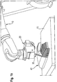
- the Fig. 1a and 1b schematically show a robot 10 to which a laying head 20 is attached.
- a workpiece carrier 40 is held on a holder 15 for the workpiece carrier.
- the laying head 20 is designed to simultaneously deposit a fiber bundle 30 of a plurality of rovings 33 on the workpiece carrier 40.
- Fig. 1a 5 there are shown five bobbins 51 of a fiber feeding mechanism 50 on which the fibers (rovings) 33 are wound and are fed from there to the laying head 20 via the fiber feeding mechanism 50.
- Fig. 1b only 4 rovings are shown schematically.
- the arrangement is used to construct a three-dimensional preform for a component made of a fiber composite material with a multi-layer, multi-axial fiber architecture (MAFA) similar to a multi-axial (MAG).
- MAFA multi-layer, multi-axial fiber architecture
- MAG multi-axial
- the fiber feed mechanism 50 preferably comprises a fiber guiding mechanism, which is preferably in the to Figs. 12, 13 of the WO 2011/128110 A1 is shown and designed for these figures type, on.
- the workpiece carrier 40 has a workpiece molding area 41 and an edge fixing area 42, as in FIG Fig. 2a ) is shown.
- the workpiece molding area 41 corresponds to the desired three-dimensional shape of the preform.
- the edge fixing area 42 serves to fix the rovings 33 in the edge area of the workpiece carrier 40.
- the fiber layer 31a consists of rovings 33 which have been deposited in this axial orientation.
- the same workpiece carrier 40 is shown, on which a second fiber layer 31b has been deposited over the first fiber layer 31a.
- the fibers of the second fiber layer 31b have an orientation of -45 degrees relative to the orientation of the first fiber layer 31a.
- a third fiber layer 31c is deposited over the second fiber layer 31b, wherein it was deposited only on a part of the workpiece carrier 40.
- the third layer 31c has an orientation of +45 degrees relative to the first layer and thus 90 degrees relative to the second layer 31b.
- the three layers 31a to 31c form a multilayer, multi-axial fiber architecture (MAFA) 31.
- MAFA multilayer, multi-axial fiber architecture
- the laying head 20 has an entrance 20e, via which the dry rovings 33 are fed to the laying head.
- the laying head 20 further has an exit 20a, from which the rovings 33 are output for depositing on the workpiece carrier 40, wherein at the output 20a a pressure roller 20r is arranged, by means of which the dispensed rovings 33 can be optionally pressed against the workpiece carrier 40.
- a fiber advancing direction V for the Direction of promotion or transport of rovings 33 located.
- a fiber conveying device 20f is provided in the fiber advancing direction V downstream of the entrance 20e of the laying head 20.
- This fiber conveying device can, for example, with a conveyor unit, as shown in the US 2009/0229760 A1 is described, be realized. Basically, such a fiber promotion according to the Eytelwein principle is known. With regard to the fiber conveying device is incidentally to the mentioned US 2009/0229760 A1 and the said WO 2011/128110 A1 directed.
- Fig. 1a schematically illustrates a fiber treatment unit 20b.
- This fiber treatment unit 20b will be described below with reference to FIGS Fig. 3a ) and b) described in more detail.
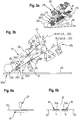
- Fig. 3a the part 20b of the laying head for guiding and treating the rovings 33 and Ri, Rj in the feed direction V downstream of the fiber conveying device 20f to the pressing roller 20r is shown in a perspective view.
- Fig. 3b the same portion 20b of the interior of the laying head 20 is schematically shown in a side view.
- the group Ri contains the even numbered rovings 33 and the group Rj contains the odd numbered rovings 33.
- the groups Ri and Rj are routed and treated on two separate paths P1 and P2.
- the division into the two groups and the separate paths P1 and P2 is not necessary. There could also be a single path without separation. On the other hand, a plurality of more than two groups and paths could also be implemented.
- the rovings 33, Ri are conveyed by the fiber conveying device 20f in the fiber advancing direction V and pass downstream to a nozzle 22, 22i for application and introduction of a medium M into the rovings, which will be described in more detail below.
- the Nozzle is adapted for applying a medium (adhesive, binder, resin, o. ⁇ .) Such that the medium applied on both sides of the rovings and introduced into the rovings (impregnated) is. This two-sided application and introduction can be continuous or clocked in sections.
- the medium is a so-called hot-melt adhesive.
- a hot-melt adhesive is tacky above a predetermined temperature and is not tacky below the predetermined temperature (hereafter referred to as the sticking temperature) but still elastic over a significant temperature range.
- a cooling device 23, 23i is provided for cooling the rovings with the adhesive applied and introduced below the sticking temperature.
- an intermediate conveying device 24, 24i is preferably provided in the feed direction V downstream of the nozzle 22, in the presence of the cooling device 23, preferably downstream of the cooling device 23.
- the intermediate conveyor device serves to safely transport the rovings downstream of the nozzle 22.
- a fiber cutting device 21, 21i is provided in the feed direction V downstream of the nozzle 22, and in the presence of the cooling device 23 and / or the intermediate conveyor 24 preferably downstream of these devices.
- the fiber cutting device 21 is adapted for cutting the rovings. With respect to specific embodiments of the fiber cutting device is on the Fig. 9 of the WO 2011/128110 A1 and their corresponding description.
- a pressure roller 1e 20r is arranged at the outlet 20a of the laying head 20.
- a heater 25, 25i1, 25i2 is provided, which is provided downstream of the fiber cutting device 21, 21i.
- the heater 25i has two elements, designated 25i1 and 25i2.
- the first element 25i1 located in the feed direction V closer to the pressure roller 20r is a final heating which serves to restore the adhesive introduced on and into the rovings 33, Ri above the adhesion temperature (eg. 100 ° C).
- the second element 25i2 is a heater for obtaining a predetermined temperature (e.g., 70 ° C) of the rovings (temperature-holding heater).
- the end of the roving 33, Ri located upstream of the cutting plane may comprise adhesive. So that this adhesive does not cool too far below the sticking temperature, this part of the roving can be kept at a temperature below but close to the sticking temperature by the - temperature holding heater 25i2.
- the laying head 20 and the robot 10 and the individual components of the laying head 20 are controlled by a control device, not shown.
- the workpiece carrier 40 is in Fig. 3 shown as a flat workpiece carrier. This serves only to simplify the presentation.
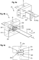
- Fig. 4a is a perspective view in the nozzle 22 shown in a schematic representation.
- a roving 33 is fed in the feed direction V via a guide track 22b formed on a projection 22P into the nozzle 22, which is flat in the embodiment shown.
- the medium (eg adhesive) M is supplied via an opening provided at the top.
- the body of the nozzle 22 downstream of the projection is shown to consist of four parts 22-1 to 22-4 which are bolted together (not shown). This is also in the page view Fig. 5c ) clearly visible.
- Fig. 4b and c) only the rear part is shown.
- a coordinate system 1-db is introduced in which the axis 1 in the longitudinal direction of the roving 33, which corresponds to the feed direction V, shows the direction d in the thickness direction of the roving and the direction b in the direction of the width of the roving shows.
- the nozzle 22 has a slot 22s, which is adapted in height and width to the dimensions of the roving 33 to be performed. The height s in the direction d of the slot corresponds to the height of the roving 33 with a predetermined allowance.
- the slot 22s thus extends in a slot plane 1-b with a height s in the direction perpendicular to the slot plane 1-b Thickness direction d. The determination of the amount will be explained below.
- the width of the slot 22s which is not provided with a reference numeral, corresponds to the width of the roving with a likewise predetermined allowance.
- the nozzle has a channel system 22k which supplies two distributors 22v with the medium M supplied via the inlet 22e. In the case of the hot-melt adhesive, this is supplied via the inlet 22e at a pressure of, for example, 50 bar.
- a distributor 22v is arranged above and below the feed-through slot 22s. From the distributor 22v located above the feedthrough slot 22s, an adhesive applicator formed as a nozzle gap 22d leads to the feedthrough slot.
- the nozzle gap 22d preferably has the width of the slot 22s.
- an adhesive applicator formed as a nozzle gap 22d leads to the same from the manifold 22v located below the feed-through slot 22s.
- this is thus applied via the nozzle column 22d on the top and bottom of a roving 33 performed.
- this can, depending on the controlled feed, in sections or clocked or continuously applied.
- the adhesive is not only applied to the roving, but impregnated into the roving, the passage slot 22s, depending on the dimensions of the roving and the nature of the adhesive or other medium and the supply pressure, in its dimensions adapted.
- a standard hot-melt adhesive with a bonding temperature of about 150 ° C and a supply pressure of about 50 bar can be 50mm roving with 12mm width and a thickness of about 0.3 mm to 0.35 mm an allowance of 0.05 to 0.1 mm may be selected to apply the hot-melt adhesive not only to the roving but also to the roving to impregnate, so to impregnate this.
- the height of the slot 22s so z. B. 0.4 mm.
- the inside width w of the gap 22d is then in the range of 0.025 to 1 mm, that is z. B. 0.05 mm.
- the allowance should be in the range of 0.025 to -0.2 mm in the height direction d and / or width direction b, for rovings with widths in the range of 5 to 100 mm and thicknesses in the range of 0.2 to 0.6 mm.
- a single feedthrough slot may be provided for all or multiple rovings of a feed path P1, P2.
- Adhesives which are suitable for the initial and final fixing of the fiber layers 31a, b, c or their intermediate fixing are suitable as media.
- media also binders and resins come into question. Binders are used to apply binders to the dry rovings in order to obtain a handleable, dry (i.e., no resin-containing) preform and to prevent slippage of the fibers during preforming.
- the application and introduction of resin can be used so that the resin does not have to be introduced into a process forming the preform in the Perform, but the impregnation with resin directly when laying the fibers happens (online prepregging). If several media are to be used, a separate nozzle 22 can be provided in each path P1, P2 for each medium.
- the application in the laying head 20, in particular with the described nozzle 22, enables dry rovings to be handled from the bobbin to the downstream of the fiber conveying device in the laying head 20 and thus at high speeds, etc.
- the described laying head or a device for constructing a three-dimensional preform for a component made of a fiber composite material with such a laying head can So with a method of in the WO 2011/12810 A1 described, be used in a very advantageous manner and this train.
- a roving 33 will, as in Fig. 6a ) can be seen over a predetermined length 1 with the medium M, which is here a hot-melt adhesive, coated and possibly impregnated.
- the length 1, the in Fig. 6a ) includes at least the predetermined lengths 11 and 12, which in Fig. 6b That is, 1 ⁇ 11 + 12.
- the roving 33 is cut by the fiber cutting device 21 at a position determined so that, after performing the cutting along the cutting plane S, the end 33e at the end of a laying web in the edge fixing region can be fixed with the adhesive M over the first predetermined length 11.
- the adhesive M having the second predetermined length 12 is provided at the downstream front end of the remaining part of the roving 33, with which the roving 33 can be fixed to the workpiece carrier 40 at the beginning of depositing the next laying line.
- the nozzle columns end in the described embodiment relative to the feed direction on a line. Alternatively, they can also be offset in the feed direction V.
- the nozzle column is preferably formed linear. Alternatively, holes arranged linearly or in a matrix are also possible as the output of the media applicator 22d.
- the downstream lip of the nozzle gap 22d may be formed projecting in the slot 22s to effect peeling (doctoring).
- the design of the nozzle 22 with the 4 parts 22-1 to 22-4 makes it possible to provide the nozzle column 22d and the slot 22s on end faces of the 4 parts, which allows easy manufacture.
- the individual elements and method steps which have been described are also disclosed separately as separate objects.
- the design of the nozzle 22 is independent of the precise design of the laying head or installation in a laying head. That too Fig. 6
- the described method can also be implemented without the laying head and / or the described nozzle.
- the medium was such.
- the construction of the nozzle was adapted accordingly. It is alternatively possible to achieve the introduction and introduction of the medium onto and into the rovings 33 with a one-sided media feed, as will be described below.
- the previous approaches of applying media such as adhesive, binder, resin have essentially taught a kind of contactless or pressureless application.
- the nozzle described above causes not only the medium is brought into contact with the rovings, but is pressed into the roving. This can also be in a one-sided media feed, so if z. B only the upper nozzle 22d in the Fig. 4 . 5 is present, if the medium is still pressed under pressure into the roving.
Landscapes
- Engineering & Computer Science (AREA)
- Chemical & Material Sciences (AREA)
- Mechanical Engineering (AREA)
- Manufacturing & Machinery (AREA)
- Composite Materials (AREA)
- Materials Engineering (AREA)
- Textile Engineering (AREA)
- Robotics (AREA)
- Moulding By Coating Moulds (AREA)
- Road Paving Structures (AREA)
- Treatment Of Fiber Materials (AREA)
Applications Claiming Priority (2)
| Application Number | Priority Date | Filing Date | Title |
|---|---|---|---|
| DE102012007439A DE102012007439A1 (de) | 2012-04-13 | 2012-04-13 | Legekopf und Vorrichtung und Verfahren zum Aufbau eines dreidimensionalen Vorformlings für ein Bauteil aus einem Faserverbundwerkstoff |
| PCT/EP2013/001056 WO2013152853A1 (de) | 2012-04-13 | 2013-04-10 | Legekopf und vorrichtung und verfahren zum aufbau eines dreidimensionalen vorformlings für ein bauteil aus einem faserverbundwerkstoff |
Publications (2)
| Publication Number | Publication Date |
|---|---|
| EP2836355A1 EP2836355A1 (de) | 2015-02-18 |
| EP2836355B1 true EP2836355B1 (de) | 2017-10-04 |
Family
ID=48143240
Family Applications (1)
| Application Number | Title | Priority Date | Filing Date |
|---|---|---|---|
| EP13717713.5A Not-in-force EP2836355B1 (de) | 2012-04-13 | 2013-04-10 | Legekopf und vorrichtung zum aufbau eines dreidimensionalen vorformlings für ein bauteil aus einem faserverbundwerkstoff |
Country Status (9)
| Country | Link |
|---|---|
| US (1) | US9782926B2 (da) |
| EP (1) | EP2836355B1 (da) |
| JP (1) | JP6117337B2 (da) |
| KR (1) | KR20150003314A (da) |
| CN (1) | CN104540662B (da) |
| CA (1) | CA2870345A1 (da) |
| DE (1) | DE102012007439A1 (da) |
| DK (1) | DK2836355T3 (da) |
| WO (1) | WO2013152853A1 (da) |
Families Citing this family (68)
| Publication number | Priority date | Publication date | Assignee | Title |
|---|---|---|---|---|
| US9511543B2 (en) | 2012-08-29 | 2016-12-06 | Cc3D Llc | Method and apparatus for continuous composite three-dimensional printing |
| US11981069B2 (en) | 2013-03-22 | 2024-05-14 | Markforged, Inc. | Three dimensional printing of composite reinforced structures |
| EP2796263B1 (en) * | 2013-04-24 | 2017-10-11 | Airbus Defence and Space GmbH | Laying die |
| DE102014201060A1 (de) | 2014-01-22 | 2015-07-23 | Broetje-Automation Gmbh | Faserlegemaschine und Verfahren zur Herstellung von Fasergelegen |
| WO2015145407A1 (en) | 2014-03-28 | 2015-10-01 | Composite Cluster Singapore Pte. Ltd. | Freespace composite manufacturing process and device |
| DE102014018933A1 (de) | 2014-12-22 | 2016-06-23 | Airbus Defence and Space GmbH | Vorrichtung zur Konsolidierung einer Preform |
| US10343330B2 (en) * | 2015-07-31 | 2019-07-09 | The Boeing Company | Systems for additively manufacturing composite parts |
| GB201518284D0 (en) * | 2015-10-15 | 2015-12-02 | Composite Technology & Applic Ltd | A method of generating a movement profile for a layup procedure |
| FR3043010B1 (fr) | 2015-10-28 | 2017-10-27 | Coriolis Composites | Machine d'application de fibres avec systemes de coupe particuliers |
| DE102015121428B4 (de) * | 2015-12-09 | 2019-10-31 | Deutsches Zentrum für Luft- und Raumfahrt e.V. | Faserlegekopf und Faserlegeanlage sowie Verfahren zur Herstellung eines Faserverbundbauteils |
| CN107116812B (zh) * | 2016-02-25 | 2023-01-17 | 科思创德国股份有限公司 | 纤维浸渍系统、拉挤设备及拉挤复合材料的制造方法 |
| FR3048373B1 (fr) * | 2016-03-07 | 2018-05-18 | Coriolis Group | Procede de realisation de preformes avec application d'un liant sur fibre seche et machine correspondante |
| KR101822269B1 (ko) * | 2016-04-05 | 2018-01-26 | 현대자동차주식회사 | 섬유토우 적층장치 및 이를 이용한 제품의 제조방법 |
| DE102016208687B4 (de) * | 2016-05-20 | 2024-06-27 | Bayerische Motoren Werke Aktiengesellschaft | Verfahren zur Herstellung eines Faser-Halbzeugs und eines Faserverbundbauteils, Faserverbundbauteil sowie Werkzeug |
| US10625467B2 (en) | 2016-09-06 | 2020-04-21 | Continuous Composites Inc. | Additive manufacturing system having adjustable curing |
| US10216165B2 (en) | 2016-09-06 | 2019-02-26 | Cc3D Llc | Systems and methods for controlling additive manufacturing |
| US10543640B2 (en) | 2016-09-06 | 2020-01-28 | Continuous Composites Inc. | Additive manufacturing system having in-head fiber teasing |
| US10759113B2 (en) | 2016-09-06 | 2020-09-01 | Continuous Composites Inc. | Additive manufacturing system having trailing cure mechanism |
| US20180065317A1 (en) | 2016-09-06 | 2018-03-08 | Cc3D Llc | Additive manufacturing system having in-situ fiber splicing |
| FR3056438B1 (fr) | 2016-09-27 | 2019-11-01 | Coriolis Group | Procede de realisation de pieces en materiau composite par impregnation d'une preforme particuliere. |
| US10717512B2 (en) | 2016-11-03 | 2020-07-21 | Continuous Composites Inc. | Composite vehicle body |
| US10953598B2 (en) | 2016-11-04 | 2021-03-23 | Continuous Composites Inc. | Additive manufacturing system having vibrating nozzle |
| US20210094230A9 (en) | 2016-11-04 | 2021-04-01 | Continuous Composites Inc. | System for additive manufacturing |
| US11117333B2 (en) | 2016-11-11 | 2021-09-14 | Rolls-Royce Plc | Composite material lay-up equipment |
| KR20180057364A (ko) * | 2016-11-22 | 2018-05-30 | 주식회사 하이인텍 | 섬유 프리폼 제조 장치 |
| KR101874404B1 (ko) * | 2016-11-22 | 2018-07-04 | 주식회사 하이인텍 | 섬유 프리폼 제조 방법 |
| GB201620227D0 (en) * | 2016-11-29 | 2017-01-11 | Cytec Ind Inc | Automated fabrication of fibrous preform |
| IT201600120462A1 (it) * | 2016-11-29 | 2018-05-29 | Domenico Brigante | Macchinario semi-automatizzato per l’impregnazione di resina di materiali compositi |
| US10857726B2 (en) | 2017-01-24 | 2020-12-08 | Continuous Composites Inc. | Additive manufacturing system implementing anchor curing |
| US10040240B1 (en) | 2017-01-24 | 2018-08-07 | Cc3D Llc | Additive manufacturing system having fiber-cutting mechanism |
| US20180229092A1 (en) | 2017-02-13 | 2018-08-16 | Cc3D Llc | Composite sporting equipment |
| US10798783B2 (en) | 2017-02-15 | 2020-10-06 | Continuous Composites Inc. | Additively manufactured composite heater |
| US10589463B2 (en) | 2017-06-29 | 2020-03-17 | Continuous Composites Inc. | Print head for additive manufacturing system |
| US10814569B2 (en) | 2017-06-29 | 2020-10-27 | Continuous Composites Inc. | Method and material for additive manufacturing |
| DE102017117383A1 (de) * | 2017-08-01 | 2019-02-07 | Airbus Operations Gmbh | Verfahren und Vorrichtung zum Reparieren eines aus einem Schichtverbundwerkstoff in mehreren Schichten aufgebauten Bauteils |
| FR3070623B1 (fr) | 2017-09-04 | 2020-10-09 | Coriolis Composites | Procede de realisation d’une piece en materiau composite par aiguilletage oriente d’une preforme |
| FR3070625B1 (fr) * | 2017-09-07 | 2020-10-09 | Coriolis Composites | Procede de realisation de preformes avec application d’un liant sur fibre seche formee de plusieurs fibres initiales |
| DE102017124417A1 (de) | 2017-10-19 | 2019-04-25 | Deutsches Zentrum für Luft- und Raumfahrt e.V. | Vorrichtung und Verfahren zum Ablegen eines Fasermaterials |
| US11491745B2 (en) | 2017-11-28 | 2022-11-08 | High In Tech Co., Ltd. | Apparatus and method for laminating fibers for direct manufacturing or preform |
| US10319499B1 (en) | 2017-11-30 | 2019-06-11 | Cc3D Llc | System and method for additively manufacturing composite wiring harness |
| US10131088B1 (en) | 2017-12-19 | 2018-11-20 | Cc3D Llc | Additive manufacturing method for discharging interlocking continuous reinforcement |
| US11167495B2 (en) | 2017-12-29 | 2021-11-09 | Continuous Composites Inc. | System and method for additively manufacturing functional elements into existing components |
| US10081129B1 (en) | 2017-12-29 | 2018-09-25 | Cc3D Llc | Additive manufacturing system implementing hardener pre-impregnation |
| US10759114B2 (en) | 2017-12-29 | 2020-09-01 | Continuous Composites Inc. | System and print head for continuously manufacturing composite structure |
| US10919222B2 (en) | 2017-12-29 | 2021-02-16 | Continuous Composites Inc. | System and method for additively manufacturing functional elements into existing components |
| US10857729B2 (en) | 2017-12-29 | 2020-12-08 | Continuous Composites Inc. | System and method for additively manufacturing functional elements into existing components |
| US11161300B2 (en) | 2018-04-11 | 2021-11-02 | Continuous Composites Inc. | System and print head for additive manufacturing system |
| US11130284B2 (en) | 2018-04-12 | 2021-09-28 | Continuous Composites Inc. | System and head for continuously manufacturing composite structure |
| US11110656B2 (en) | 2018-04-12 | 2021-09-07 | Continuous Composites Inc. | System for continuously manufacturing composite structure |
| US11052603B2 (en) | 2018-06-07 | 2021-07-06 | Continuous Composites Inc. | Additive manufacturing system having stowable cutting mechanism |
| DE102018115392B4 (de) * | 2018-06-26 | 2022-09-22 | Azl Aachen Gmbh | Verfahren und Vorrichtung zur Produktion von Faserverbundwerkstoff aufweisenden Werkstücken |
| US20200086563A1 (en) | 2018-09-13 | 2020-03-19 | Cc3D Llc | System and head for continuously manufacturing composite structure |
| CN109094055B (zh) * | 2018-09-29 | 2020-06-19 | 西安交通大学 | 一种组合式多通道连续干纤维3d打印复合材料成形装置 |
| US11235522B2 (en) | 2018-10-04 | 2022-02-01 | Continuous Composites Inc. | System for additively manufacturing composite structures |
| US11511480B2 (en) | 2018-10-26 | 2022-11-29 | Continuous Composites Inc. | System for additive manufacturing |
| US11358331B2 (en) | 2018-11-19 | 2022-06-14 | Continuous Composites Inc. | System and head for continuously manufacturing composite structure |
| US11420390B2 (en) | 2018-11-19 | 2022-08-23 | Continuous Composites Inc. | System for additively manufacturing composite structure |
| US20200238603A1 (en) * | 2019-01-25 | 2020-07-30 | Continuous Composites Inc. | System for additively manufacturing composite structure |
| US20200376758A1 (en) | 2019-05-28 | 2020-12-03 | Continuous Composites Inc. | System for additively manufacturing composite structure |
| US11840022B2 (en) | 2019-12-30 | 2023-12-12 | Continuous Composites Inc. | System and method for additive manufacturing |
| US11904534B2 (en) | 2020-02-25 | 2024-02-20 | Continuous Composites Inc. | Additive manufacturing system |
| JP2021137923A (ja) * | 2020-03-05 | 2021-09-16 | 津田駒工業株式会社 | 自動繊維束配置装置 |
| US11926100B2 (en) | 2020-06-23 | 2024-03-12 | Continuous Composites Inc. | Systems and methods for controlling additive manufacturing |
| US11465348B2 (en) | 2020-09-11 | 2022-10-11 | Continuous Composites Inc. | Print head for additive manufacturing system |
| US11926099B2 (en) | 2021-04-27 | 2024-03-12 | Continuous Composites Inc. | Additive manufacturing system |
| US20230118530A1 (en) | 2021-10-20 | 2023-04-20 | Continuous Composites Inc. | Systems and methods for additive manufacturing |
| US12600084B2 (en) | 2022-05-12 | 2026-04-14 | Continuous Composites Inc. | Additive manufacturing system |
| US12391010B2 (en) | 2023-01-13 | 2025-08-19 | Rtx Corporation | Methods of manufacture for composite blades |
Family Cites Families (47)
| Publication number | Priority date | Publication date | Assignee | Title |
|---|---|---|---|---|
| GB828110A (en) | 1956-08-22 | 1960-02-17 | Polyplex Danish American Plast | Improvements in or relating to the manufacture of reinforced synthetic resin articles |
| US3115678A (en) | 1960-10-07 | 1963-12-31 | Collins & Aikman Corp | Apparatus for molding plastic carpets |
| JPS50129662A (da) * | 1974-04-03 | 1975-10-14 | ||
| DE3003666A1 (de) | 1980-02-01 | 1981-08-06 | Richard 4937 Lage Pott | Gelege zur herstellung einer verstaerkung von im wesentlichen aus flaechen bestehenden bauteilen und eine vorrichtung zur herstellung desselben |
| CH644879A5 (en) | 1980-03-17 | 1984-08-31 | Herbert Schreiber | Process for the production of fibre-reinforced plastic articles |
| US4432716A (en) | 1981-03-20 | 1984-02-21 | Lignotock Verfahrenstechnik Gmbh | Apparatus for moulding three-dimensionally shaped moulded articles from binder-containing web-like non-woven fabrics |
| JPH0414191Y2 (da) * | 1987-07-23 | 1992-03-31 | ||
| US5134002A (en) | 1989-08-28 | 1992-07-28 | United Technologies Corporation | Mold liners for resin transfer molding |
| US5110395A (en) * | 1989-12-04 | 1992-05-05 | Cincinnati Milacron Inc. | Fiber placement head |
| JPH0778293B2 (ja) | 1990-03-30 | 1995-08-23 | 東レ株式会社 | 捲縮付与装置および捲縮線状体の製造方法 |
| DE4115831A1 (de) | 1991-05-15 | 1992-11-19 | Bayer Ag | Kontinuierliche herstellung von verbundwerkstoffen |
| US5344687A (en) | 1991-09-27 | 1994-09-06 | Brunswick Technologies, Inc. | Structurally reinforced thermoplastic-fabric composite construction materials that are moldable |
| FR2705655B1 (fr) | 1993-05-26 | 1995-08-25 | Aerospatiale | Machine pour le bobinage-déposé au contact simultané d'une pluralité de fils individuels. |
| US5766357A (en) * | 1996-09-19 | 1998-06-16 | Alliant Techsystems Inc. | Apparatus for fiber impregnation |
| FR2761380B1 (fr) | 1997-03-28 | 1999-07-02 | Europ Propulsion | Procede et machine pour la realisation de nappes fibreuses multiaxiales |
| EP0884153B1 (en) | 1997-06-10 | 2001-09-12 | Trevira Gmbh | A method for use in the production of a fiber reinforced three-dimensional product |
| US6544367B1 (en) * | 1999-02-01 | 2003-04-08 | Alliant Techsystems Inc. | Overwrap tape end-effector for fiber placement/winding machines |
| DE19922799B4 (de) | 1999-05-18 | 2014-06-12 | Bayerische Motoren Werke Aktiengesellschaft | Verfahren zur Herstellung eines Kunststoffformteils |
| DE10005202B4 (de) | 2000-02-03 | 2007-03-01 | Institut Für Verbundwerkstoffe Gmbh | Verfahren und Vorrichtung zur kontinuierlichen bauteil- und prozessorientierten Herstellung von Verstärkungsstruktur-Halbzeugen für Faser-Kunststoff-Verbundwerkstoffe |
| US6771874B2 (en) | 2002-01-11 | 2004-08-03 | Otuma, Inc. | Tension-assisted mounting of fibers on a substrate |
| JP4309339B2 (ja) | 2002-05-29 | 2009-08-05 | ソシエテ ド テクノロジー ミシュラン | ストリップを回転表面に取り付けるための装置および方法 |
| DE10250826B4 (de) | 2002-10-31 | 2008-05-29 | Airbus Deutschland Gmbh | Verfahren zur Herstellung eines dreidimensionalen Preforms |
| ITTO20040198A1 (it) | 2004-03-23 | 2004-06-23 | Alenia Aeronautica Spa | Procedimento per la fabbricazione di una preforma secca di rinforzo per un elemento strutturale composito di un aeromobile |
| FR2882681B1 (fr) * | 2005-03-03 | 2009-11-20 | Coriolis Composites | Tete d'application de fibres et machine correspondante |
| EP1724098A1 (en) | 2005-05-20 | 2006-11-22 | Carbo Tech Composites GmbH | Process for the production of a laminated composite product and a composite product made by the lamination process |
| DE102005034393B4 (de) | 2005-07-22 | 2009-04-02 | Airbus Deutschland Gmbh | Verfahren zur Herstellung von ein- oder mehrschichtigen Faservorformlingen im TFP-Verfahren |
| NL1032830C2 (nl) | 2006-11-07 | 2008-05-08 | Cats Beheer & Findings B V | Inrichting voor het op onderling gelijke spanningen brengen van langwerpige flexibele elementen. |
| JP5098435B2 (ja) | 2007-05-21 | 2012-12-12 | 株式会社豊田自動織機 | 繊維束配列装置 |
| GB2452298B (en) | 2007-08-30 | 2010-01-13 | Gkn Aerospace Services Ltd | Composite structure |
| CN101462358B (zh) | 2007-12-19 | 2013-09-11 | 维斯塔斯风力系统有限公司 | 一种制备预成型件的设备 |
| DE102008017573A1 (de) | 2008-04-07 | 2010-04-15 | Airbus Deutschland Gmbh | Verfahren zur Herstellung eines FVW/FVK-Bauteils aus Rovings mit einem Formwerkzeug und Formwerkzeug zur Durchführung des Verfahrens |
| DE102008019147A1 (de) | 2008-04-16 | 2009-10-22 | Airbus Deutschland Gmbh | Verfahren zur Herstellung von Faservorformlingen |
| EP2301045B1 (en) * | 2008-06-27 | 2013-02-20 | Union Carbide Chemicals & Plastics Technology LLC | Pultrusion process for the manufacture of fiber reinforced composites |
| FR2937582B1 (fr) * | 2008-10-28 | 2010-12-17 | Coriolis Composites | Machine d'application de fibres avec tubes flexibles d'acheminement de fibres places dans une gaine froide |
| CN102459458B (zh) | 2009-05-07 | 2015-05-20 | 国际壳牌研究有限公司 | 粘合剂组合物和柏油混合料 |
| FR2948660B1 (fr) | 2009-07-30 | 2011-08-19 | Oroxcell | Derives de 2-amino-2-phenyl-alkanol, leur preparation et les compositions pharmaceutiques qui les contiennent |
| US8037843B2 (en) | 2009-10-08 | 2011-10-18 | General Electric Company | Resin application and infusion system |
| DE102010015199B9 (de) | 2010-04-16 | 2013-08-01 | Compositence Gmbh | Faserführungsvorrichtung und Vorrichtung zum Aufbau eines dreidimensionalen Vorformlings |
| DE102010040970A1 (de) | 2010-09-17 | 2012-03-22 | Airbus Operations Gmbh | Verfahren und Vorrichtung zur Bereitstellung eines trockenen textilen Vorformlings |
| US20120073726A1 (en) * | 2010-09-24 | 2012-03-29 | General Electric Company | Resin Delivery, Application and Infusion System and Integrated Layup System and Method of Use |
| US8282758B2 (en) | 2010-09-24 | 2012-10-09 | General Electric Company | System and method for the automated delivery and layup of resin infused fibers |
| CN201950820U (zh) * | 2010-12-22 | 2011-08-31 | 南京诺尔泰复合材料设备制造有限公司 | 带有轴向纤维的复合材料管的制备装置 |
| DE102011007021A1 (de) | 2011-04-08 | 2012-10-11 | Voith Patent Gmbh | Vorrichtung und Verfahren zur Herstellung von Faservorformlingen, die insbesondere eine Vorstufe bei der Herstellung von faserverstärkten Kunststoff-Bauteilen darstellen |
| DE102011007018A1 (de) | 2011-04-08 | 2012-10-11 | Voith Patent Gmbh | Vorrichtung und Verfahren zur Herstellung von Faservorformlingen, die insbesondere eine Vorstufe bei der Herstellung von faserverstärkten Kunststoff-Bauteilen darstellen |
| DE102011007022A1 (de) | 2011-04-08 | 2012-10-11 | Voith Patent Gmbh | Vorrichtung und Verfahren zur Herstellung von Faservorformlingen, die insbesondere eine Vorstufe bei der Herstellung von faserverstärkten Kunststoff-Bauteilen darstellen |
| DE102011007020A1 (de) | 2011-04-08 | 2012-10-11 | Voith Patent Gmbh | Vorrichtung und Verfahren zur Herstellung von Faserformlingen, die insbesondere eine Vorstufe bei der Herstellung von faserverstärkten Kunststoff-Bauteilen darstellen |
| DE102011100640A1 (de) | 2011-05-05 | 2012-11-08 | Compositence Gmbh | Verfahren und Vorrichtung zum Herstellen von Fasergelegen und Bauteilvorformlingen aus Fasern |
-
2012
- 2012-04-13 DE DE102012007439A patent/DE102012007439A1/de not_active Withdrawn
-
2013
- 2013-04-10 US US14/394,182 patent/US9782926B2/en not_active Expired - Fee Related
- 2013-04-10 DK DK13717713.5T patent/DK2836355T3/da active
- 2013-04-10 WO PCT/EP2013/001056 patent/WO2013152853A1/de not_active Ceased
- 2013-04-10 KR KR1020147031731A patent/KR20150003314A/ko not_active Abandoned
- 2013-04-10 CA CA2870345A patent/CA2870345A1/en not_active Abandoned
- 2013-04-10 JP JP2015504879A patent/JP6117337B2/ja not_active Expired - Fee Related
- 2013-04-10 CN CN201380025905.8A patent/CN104540662B/zh not_active Expired - Fee Related
- 2013-04-10 EP EP13717713.5A patent/EP2836355B1/de not_active Not-in-force
Non-Patent Citations (1)
| Title |
|---|
| None * |
Also Published As
| Publication number | Publication date |
|---|---|
| JP6117337B2 (ja) | 2017-04-19 |
| DE102012007439A1 (de) | 2013-10-17 |
| US20150314522A1 (en) | 2015-11-05 |
| EP2836355A1 (de) | 2015-02-18 |
| CA2870345A1 (en) | 2013-10-17 |
| KR20150003314A (ko) | 2015-01-08 |
| JP2015514030A (ja) | 2015-05-18 |
| CN104540662A (zh) | 2015-04-22 |
| WO2013152853A1 (de) | 2013-10-17 |
| DK2836355T3 (da) | 2018-01-02 |
| US9782926B2 (en) | 2017-10-10 |
| CN104540662B (zh) | 2016-12-14 |
Similar Documents
| Publication | Publication Date | Title |
|---|---|---|
| EP2836355B1 (de) | Legekopf und vorrichtung zum aufbau eines dreidimensionalen vorformlings für ein bauteil aus einem faserverbundwerkstoff | |
| DE60003766T2 (de) | Verfahren und Vorrichtung zur Herstellung eines Verbundbandes geformt aus Verstärkungsfasern und thermoplastischem Material | |
| DE102010015199B9 (de) | Faserführungsvorrichtung und Vorrichtung zum Aufbau eines dreidimensionalen Vorformlings | |
| DE602004008366T2 (de) | Verfahren und Vorrichtung zur Herstellung einer Vorform eines Verstärkungselementes | |
| EP3386735B1 (de) | Ablagevorrichtung für faserrovings | |
| DE102013107103B4 (de) | Faserhalbzeug-Ablegekopf und Faser-Legevorrichtung | |
| DE102009042384B4 (de) | Verfahren und Einrichtung zum Aufbringen einer unidirektionalen Faserlage auf eine sich bewegende Unterstützung und Verfahren zum Herstellen eines Multiaxialgeleges | |
| EP2822754B1 (de) | Querablegen von fasern | |
| DE102008011410A1 (de) | Verfahren zur Herstellung eines profilierten Preforms und eines profilierten FVK-Bauteils, Pultrusionsanlage sowie Press-Vorrichtung zur Durchführung des Verfahrens | |
| EP1907194B1 (de) | Führungsmittel für eine vorrichtung zur herstellung von faservorformlingen im tfp-verfahren für verbundbauteile | |
| EP3424690B1 (de) | Verfahren und vorrichtung zur herstellung eines bewehrungsgitters | |
| EP2181217B1 (de) | Verfahren und vorrichtung zur kontinuierlichen herstellung einer multiaxialen gelegebahn | |
| EP4041537A1 (de) | Pultrusionsvorrichtung für gekrümmte profile | |
| DE3132697A1 (de) | Verfahren und vorrichtung zur herstellung eines geleges | |
| EP2631050A1 (de) | Verfahren und Vorrichtung zum Erzeugen eines Verbundwerkstoffs | |
| AT522285B1 (de) | Verfahren und vorrichtung zur additiven herstellung von hochfesten bauteilen | |
| DE102016110323B4 (de) | Fasertemperiereinrichtung, Faserappliziervorrichtung, Faserlegeanlage sowie Verfahren zum Temperieren | |
| EP1124656B1 (de) | Verfahren und anlage zum kontinuierlichen herstellen von bauelementen | |
| EP2821211A1 (de) | Faserhalbzeug-Fördervorrichtung | |
| WO2014012774A1 (de) | Vorrichtung und verfahren zur herstellung von faserverstärkten kunststoffbauteilen | |
| EP3257663B1 (de) | Verfahren zum herstellen von halbzeugen für faser-kunststoff-verbundbauteile | |
| DE102018109212B4 (de) | Verfahren und Anlage zum Herstellen einer Faserpreform sowie Verfahren zur Herstellung eines Faserverbundbauteils | |
| DE102017124417A1 (de) | Vorrichtung und Verfahren zum Ablegen eines Fasermaterials | |
| EP3814121A1 (de) | Verfahren und vorrichtung zur produktion von faserverbundwerkstoff aufweisenden werkstücken | |
| WO2008055460A2 (de) | Verfahren und vorrichtung zur kontinuierlichen herstellung von prepregs |
Legal Events
| Date | Code | Title | Description |
|---|---|---|---|
| PUAI | Public reference made under article 153(3) epc to a published international application that has entered the european phase |
Free format text: ORIGINAL CODE: 0009012 |
|
| 17P | Request for examination filed |
Effective date: 20141024 |
|
| AK | Designated contracting states |
Kind code of ref document: A1 Designated state(s): AL AT BE BG CH CY CZ DE DK EE ES FI FR GB GR HR HU IE IS IT LI LT LU LV MC MK MT NL NO PL PT RO RS SE SI SK SM TR |
|
| AX | Request for extension of the european patent |
Extension state: BA ME |
|
| DAX | Request for extension of the european patent (deleted) | ||
| GRAP | Despatch of communication of intention to grant a patent |
Free format text: ORIGINAL CODE: EPIDOSNIGR1 |
|
| RIC1 | Information provided on ipc code assigned before grant |
Ipc: B29B 11/16 20060101ALI20170223BHEP Ipc: B29C 70/38 20060101AFI20170223BHEP Ipc: B29B 15/12 20060101ALI20170223BHEP Ipc: B29C 70/54 20060101ALI20170223BHEP |
|
| INTG | Intention to grant announced |
Effective date: 20170329 |
|
| GRAS | Grant fee paid |
Free format text: ORIGINAL CODE: EPIDOSNIGR3 |
|
| GRAJ | Information related to disapproval of communication of intention to grant by the applicant or resumption of examination proceedings by the epo deleted |
Free format text: ORIGINAL CODE: EPIDOSDIGR1 |
|
| GRAL | Information related to payment of fee for publishing/printing deleted |
Free format text: ORIGINAL CODE: EPIDOSDIGR3 |
|
| GRAR | Information related to intention to grant a patent recorded |
Free format text: ORIGINAL CODE: EPIDOSNIGR71 |
|
| GRAA | (expected) grant |
Free format text: ORIGINAL CODE: 0009210 |
|
| INTC | Intention to grant announced (deleted) | ||
| INTG | Intention to grant announced |
Effective date: 20170824 |
|
| AK | Designated contracting states |
Kind code of ref document: B1 Designated state(s): AL AT BE BG CH CY CZ DE DK EE ES FI FR GB GR HR HU IE IS IT LI LT LU LV MC MK MT NL NO PL PT RO RS SE SI SK SM TR |
|
| REG | Reference to a national code |
Ref country code: GB Ref legal event code: FG4D Free format text: NOT ENGLISH |
|
| REG | Reference to a national code |
Ref country code: CH Ref legal event code: EP |
|
| REG | Reference to a national code |
Ref country code: AT Ref legal event code: REF Ref document number: 933602 Country of ref document: AT Kind code of ref document: T Effective date: 20171015 |
|
| REG | Reference to a national code |
Ref country code: IE Ref legal event code: FG4D Free format text: LANGUAGE OF EP DOCUMENT: GERMAN |
|
| REG | Reference to a national code |
Ref country code: DE Ref legal event code: R096 Ref document number: 502013008490 Country of ref document: DE |
|
| REG | Reference to a national code |
Ref country code: NL Ref legal event code: FP |
|
| REG | Reference to a national code |
Ref country code: DK Ref legal event code: T3 Effective date: 20171220 |
|
| REG | Reference to a national code |
Ref country code: LT Ref legal event code: MG4D |
|
| REG | Reference to a national code |
Ref country code: FR Ref legal event code: PLFP Year of fee payment: 6 |
|
| PG25 | Lapsed in a contracting state [announced via postgrant information from national office to epo] |
Ref country code: LT Free format text: LAPSE BECAUSE OF FAILURE TO SUBMIT A TRANSLATION OF THE DESCRIPTION OR TO PAY THE FEE WITHIN THE PRESCRIBED TIME-LIMIT Effective date: 20171004 Ref country code: FI Free format text: LAPSE BECAUSE OF FAILURE TO SUBMIT A TRANSLATION OF THE DESCRIPTION OR TO PAY THE FEE WITHIN THE PRESCRIBED TIME-LIMIT Effective date: 20171004 Ref country code: SE Free format text: LAPSE BECAUSE OF FAILURE TO SUBMIT A TRANSLATION OF THE DESCRIPTION OR TO PAY THE FEE WITHIN THE PRESCRIBED TIME-LIMIT Effective date: 20171004 Ref country code: ES Free format text: LAPSE BECAUSE OF FAILURE TO SUBMIT A TRANSLATION OF THE DESCRIPTION OR TO PAY THE FEE WITHIN THE PRESCRIBED TIME-LIMIT Effective date: 20171004 Ref country code: NO Free format text: LAPSE BECAUSE OF FAILURE TO SUBMIT A TRANSLATION OF THE DESCRIPTION OR TO PAY THE FEE WITHIN THE PRESCRIBED TIME-LIMIT Effective date: 20180104 |
|
| PG25 | Lapsed in a contracting state [announced via postgrant information from national office to epo] |
Ref country code: IS Free format text: LAPSE BECAUSE OF FAILURE TO SUBMIT A TRANSLATION OF THE DESCRIPTION OR TO PAY THE FEE WITHIN THE PRESCRIBED TIME-LIMIT Effective date: 20180204 Ref country code: GR Free format text: LAPSE BECAUSE OF FAILURE TO SUBMIT A TRANSLATION OF THE DESCRIPTION OR TO PAY THE FEE WITHIN THE PRESCRIBED TIME-LIMIT Effective date: 20180105 Ref country code: LV Free format text: LAPSE BECAUSE OF FAILURE TO SUBMIT A TRANSLATION OF THE DESCRIPTION OR TO PAY THE FEE WITHIN THE PRESCRIBED TIME-LIMIT Effective date: 20171004 Ref country code: BG Free format text: LAPSE BECAUSE OF FAILURE TO SUBMIT A TRANSLATION OF THE DESCRIPTION OR TO PAY THE FEE WITHIN THE PRESCRIBED TIME-LIMIT Effective date: 20180104 Ref country code: RS Free format text: LAPSE BECAUSE OF FAILURE TO SUBMIT A TRANSLATION OF THE DESCRIPTION OR TO PAY THE FEE WITHIN THE PRESCRIBED TIME-LIMIT Effective date: 20171004 Ref country code: HR Free format text: LAPSE BECAUSE OF FAILURE TO SUBMIT A TRANSLATION OF THE DESCRIPTION OR TO PAY THE FEE WITHIN THE PRESCRIBED TIME-LIMIT Effective date: 20171004 |
|
| PGFP | Annual fee paid to national office [announced via postgrant information from national office to epo] |
Ref country code: NL Payment date: 20180423 Year of fee payment: 6 |
|
| REG | Reference to a national code |
Ref country code: DE Ref legal event code: R097 Ref document number: 502013008490 Country of ref document: DE |
|
| PG25 | Lapsed in a contracting state [announced via postgrant information from national office to epo] |
Ref country code: CZ Free format text: LAPSE BECAUSE OF FAILURE TO SUBMIT A TRANSLATION OF THE DESCRIPTION OR TO PAY THE FEE WITHIN THE PRESCRIBED TIME-LIMIT Effective date: 20171004 Ref country code: EE Free format text: LAPSE BECAUSE OF FAILURE TO SUBMIT A TRANSLATION OF THE DESCRIPTION OR TO PAY THE FEE WITHIN THE PRESCRIBED TIME-LIMIT Effective date: 20171004 Ref country code: SK Free format text: LAPSE BECAUSE OF FAILURE TO SUBMIT A TRANSLATION OF THE DESCRIPTION OR TO PAY THE FEE WITHIN THE PRESCRIBED TIME-LIMIT Effective date: 20171004 |
|
| PGFP | Annual fee paid to national office [announced via postgrant information from national office to epo] |
Ref country code: DK Payment date: 20180424 Year of fee payment: 6 |
|
| PLBE | No opposition filed within time limit |
Free format text: ORIGINAL CODE: 0009261 |
|
| STAA | Information on the status of an ep patent application or granted ep patent |
Free format text: STATUS: NO OPPOSITION FILED WITHIN TIME LIMIT |
|
| PG25 | Lapsed in a contracting state [announced via postgrant information from national office to epo] |
Ref country code: RO Free format text: LAPSE BECAUSE OF FAILURE TO SUBMIT A TRANSLATION OF THE DESCRIPTION OR TO PAY THE FEE WITHIN THE PRESCRIBED TIME-LIMIT Effective date: 20171004 Ref country code: IT Free format text: LAPSE BECAUSE OF FAILURE TO SUBMIT A TRANSLATION OF THE DESCRIPTION OR TO PAY THE FEE WITHIN THE PRESCRIBED TIME-LIMIT Effective date: 20171004 Ref country code: SM Free format text: LAPSE BECAUSE OF FAILURE TO SUBMIT A TRANSLATION OF THE DESCRIPTION OR TO PAY THE FEE WITHIN THE PRESCRIBED TIME-LIMIT Effective date: 20171004 Ref country code: PL Free format text: LAPSE BECAUSE OF FAILURE TO SUBMIT A TRANSLATION OF THE DESCRIPTION OR TO PAY THE FEE WITHIN THE PRESCRIBED TIME-LIMIT Effective date: 20171004 |
|
| PGFP | Annual fee paid to national office [announced via postgrant information from national office to epo] |
Ref country code: BE Payment date: 20180530 Year of fee payment: 6 |
|
| 26N | No opposition filed |
Effective date: 20180705 |
|
| PG25 | Lapsed in a contracting state [announced via postgrant information from national office to epo] |
Ref country code: MT Free format text: LAPSE BECAUSE OF FAILURE TO SUBMIT A TRANSLATION OF THE DESCRIPTION OR TO PAY THE FEE WITHIN THE PRESCRIBED TIME-LIMIT Effective date: 20171004 |
|
| PG25 | Lapsed in a contracting state [announced via postgrant information from national office to epo] |
Ref country code: MC Free format text: LAPSE BECAUSE OF FAILURE TO SUBMIT A TRANSLATION OF THE DESCRIPTION OR TO PAY THE FEE WITHIN THE PRESCRIBED TIME-LIMIT Effective date: 20171004 Ref country code: SI Free format text: LAPSE BECAUSE OF FAILURE TO SUBMIT A TRANSLATION OF THE DESCRIPTION OR TO PAY THE FEE WITHIN THE PRESCRIBED TIME-LIMIT Effective date: 20171004 |
|
| REG | Reference to a national code |
Ref country code: CH Ref legal event code: PL |
|
| REG | Reference to a national code |
Ref country code: BE Ref legal event code: MM Effective date: 20180430 |
|
| REG | Reference to a national code |
Ref country code: IE Ref legal event code: MM4A |
|
| PG25 | Lapsed in a contracting state [announced via postgrant information from national office to epo] |
Ref country code: LU Free format text: LAPSE BECAUSE OF NON-PAYMENT OF DUE FEES Effective date: 20180410 |
|
| PG25 | Lapsed in a contracting state [announced via postgrant information from national office to epo] |
Ref country code: LI Free format text: LAPSE BECAUSE OF NON-PAYMENT OF DUE FEES Effective date: 20180430 Ref country code: BE Free format text: LAPSE BECAUSE OF NON-PAYMENT OF DUE FEES Effective date: 20180430 Ref country code: CH Free format text: LAPSE BECAUSE OF NON-PAYMENT OF DUE FEES Effective date: 20180430 |
|
| PG25 | Lapsed in a contracting state [announced via postgrant information from national office to epo] |
Ref country code: IE Free format text: LAPSE BECAUSE OF NON-PAYMENT OF DUE FEES Effective date: 20180410 |
|
| REG | Reference to a national code |
Ref country code: DK Ref legal event code: EBP Effective date: 20190430 |
|
| REG | Reference to a national code |
Ref country code: NL Ref legal event code: MM Effective date: 20190501 |
|
| REG | Reference to a national code |
Ref country code: AT Ref legal event code: MM01 Ref document number: 933602 Country of ref document: AT Kind code of ref document: T Effective date: 20190410 |
|
| PG25 | Lapsed in a contracting state [announced via postgrant information from national office to epo] |
Ref country code: AT Free format text: LAPSE BECAUSE OF NON-PAYMENT OF DUE FEES Effective date: 20190410 Ref country code: NL Free format text: LAPSE BECAUSE OF NON-PAYMENT OF DUE FEES Effective date: 20190501 |
|
| PG25 | Lapsed in a contracting state [announced via postgrant information from national office to epo] |
Ref country code: TR Free format text: LAPSE BECAUSE OF FAILURE TO SUBMIT A TRANSLATION OF THE DESCRIPTION OR TO PAY THE FEE WITHIN THE PRESCRIBED TIME-LIMIT Effective date: 20171004 |
|
| PG25 | Lapsed in a contracting state [announced via postgrant information from national office to epo] |
Ref country code: DK Free format text: LAPSE BECAUSE OF NON-PAYMENT OF DUE FEES Effective date: 20190430 |
|
| PG25 | Lapsed in a contracting state [announced via postgrant information from national office to epo] |
Ref country code: PT Free format text: LAPSE BECAUSE OF FAILURE TO SUBMIT A TRANSLATION OF THE DESCRIPTION OR TO PAY THE FEE WITHIN THE PRESCRIBED TIME-LIMIT Effective date: 20171004 Ref country code: HU Free format text: LAPSE BECAUSE OF FAILURE TO SUBMIT A TRANSLATION OF THE DESCRIPTION OR TO PAY THE FEE WITHIN THE PRESCRIBED TIME-LIMIT; INVALID AB INITIO Effective date: 20130410 |
|
| PG25 | Lapsed in a contracting state [announced via postgrant information from national office to epo] |
Ref country code: CY Free format text: LAPSE BECAUSE OF FAILURE TO SUBMIT A TRANSLATION OF THE DESCRIPTION OR TO PAY THE FEE WITHIN THE PRESCRIBED TIME-LIMIT Effective date: 20171004 Ref country code: MK Free format text: LAPSE BECAUSE OF NON-PAYMENT OF DUE FEES Effective date: 20171004 |
|
| PG25 | Lapsed in a contracting state [announced via postgrant information from national office to epo] |
Ref country code: AL Free format text: LAPSE BECAUSE OF FAILURE TO SUBMIT A TRANSLATION OF THE DESCRIPTION OR TO PAY THE FEE WITHIN THE PRESCRIBED TIME-LIMIT Effective date: 20171004 |
|
| PGFP | Annual fee paid to national office [announced via postgrant information from national office to epo] |
Ref country code: GB Payment date: 20200423 Year of fee payment: 8 |
|
| PGFP | Annual fee paid to national office [announced via postgrant information from national office to epo] |
Ref country code: FR Payment date: 20210421 Year of fee payment: 9 |
|
| GBPC | Gb: european patent ceased through non-payment of renewal fee |
Effective date: 20210410 |
|
| PG25 | Lapsed in a contracting state [announced via postgrant information from national office to epo] |
Ref country code: GB Free format text: LAPSE BECAUSE OF NON-PAYMENT OF DUE FEES Effective date: 20210410 |
|
| PGFP | Annual fee paid to national office [announced via postgrant information from national office to epo] |
Ref country code: DE Payment date: 20220509 Year of fee payment: 10 |
|
| PG25 | Lapsed in a contracting state [announced via postgrant information from national office to epo] |
Ref country code: FR Free format text: LAPSE BECAUSE OF NON-PAYMENT OF DUE FEES Effective date: 20220430 |
|
| REG | Reference to a national code |
Ref country code: DE Ref legal event code: R119 Ref document number: 502013008490 Country of ref document: DE |
|
| PG25 | Lapsed in a contracting state [announced via postgrant information from national office to epo] |
Ref country code: DE Free format text: LAPSE BECAUSE OF NON-PAYMENT OF DUE FEES Effective date: 20231103 |