EP2836724B1 - Système fluidique et métode - Google Patents
Système fluidique et métode Download PDFInfo
- Publication number
- EP2836724B1 EP2836724B1 EP13709779.6A EP13709779A EP2836724B1 EP 2836724 B1 EP2836724 B1 EP 2836724B1 EP 13709779 A EP13709779 A EP 13709779A EP 2836724 B1 EP2836724 B1 EP 2836724B1
- Authority
- EP
- European Patent Office
- Prior art keywords
- actuator
- control
- fluid
- safety
- valve control
- Prior art date
- Legal status (The legal status is an assumption and is not a legal conclusion. Google has not performed a legal analysis and makes no representation as to the accuracy of the status listed.)
- Not-in-force
Links
Images

Classifications
-
- G—PHYSICS
- G05—CONTROLLING; REGULATING
- G05B—CONTROL OR REGULATING SYSTEMS IN GENERAL; FUNCTIONAL ELEMENTS OF SUCH SYSTEMS; MONITORING OR TESTING ARRANGEMENTS FOR SUCH SYSTEMS OR ELEMENTS
- G05B19/00—Program-control systems
- G05B19/02—Program-control systems electric
- G05B19/04—Program control other than numerical control, i.e. in sequence controllers or logic controllers
- G05B19/042—Program control other than numerical control, i.e. in sequence controllers or logic controllers using digital processors
- G05B19/0428—Safety, monitoring
-
- F—MECHANICAL ENGINEERING; LIGHTING; HEATING; WEAPONS; BLASTING
- F15—FLUID-PRESSURE ACTUATORS; HYDRAULICS OR PNEUMATICS IN GENERAL
- F15B—SYSTEMS ACTING BY MEANS OF FLUIDS IN GENERAL; FLUID-PRESSURE ACTUATORS, e.g. SERVOMOTORS; DETAILS OF FLUID-PRESSURE SYSTEMS, NOT OTHERWISE PROVIDED FOR
- F15B19/00—Testing; Calibrating; Fault detection or monitoring; Simulation or modelling of fluid-pressure systems or apparatus not otherwise provided for
- F15B19/005—Fault detection or monitoring
-
- F—MECHANICAL ENGINEERING; LIGHTING; HEATING; WEAPONS; BLASTING
- F15—FLUID-PRESSURE ACTUATORS; HYDRAULICS OR PNEUMATICS IN GENERAL
- F15B—SYSTEMS ACTING BY MEANS OF FLUIDS IN GENERAL; FLUID-PRESSURE ACTUATORS, e.g. SERVOMOTORS; DETAILS OF FLUID-PRESSURE SYSTEMS, NOT OTHERWISE PROVIDED FOR
- F15B19/00—Testing; Calibrating; Fault detection or monitoring; Simulation or modelling of fluid-pressure systems or apparatus not otherwise provided for
-
- F—MECHANICAL ENGINEERING; LIGHTING; HEATING; WEAPONS; BLASTING
- F16—ENGINEERING ELEMENTS AND UNITS; GENERAL MEASURES FOR PRODUCING AND MAINTAINING EFFECTIVE FUNCTIONING OF MACHINES OR INSTALLATIONS; THERMAL INSULATION IN GENERAL
- F16P—SAFETY DEVICES IN GENERAL; SAFETY DEVICES FOR PRESSES
- F16P3/00—Safety devices acting in conjunction with the control or operation of a machine; Control arrangements requiring the simultaneous use of two or more parts of the body
- F16P3/12—Safety devices acting in conjunction with the control or operation of a machine; Control arrangements requiring the simultaneous use of two or more parts of the body with means, e.g. feelers, which in case of the presence of a body part of a person in or near the danger zone influence the control or operation of the machine
- F16P3/14—Safety devices acting in conjunction with the control or operation of a machine; Control arrangements requiring the simultaneous use of two or more parts of the body with means, e.g. feelers, which in case of the presence of a body part of a person in or near the danger zone influence the control or operation of the machine the means being photocells or other devices sensitive without mechanical contact
- F16P3/142—Safety devices acting in conjunction with the control or operation of a machine; Control arrangements requiring the simultaneous use of two or more parts of the body with means, e.g. feelers, which in case of the presence of a body part of a person in or near the danger zone influence the control or operation of the machine the means being photocells or other devices sensitive without mechanical contact using image capturing devices
-
- F—MECHANICAL ENGINEERING; LIGHTING; HEATING; WEAPONS; BLASTING
- F16—ENGINEERING ELEMENTS AND UNITS; GENERAL MEASURES FOR PRODUCING AND MAINTAINING EFFECTIVE FUNCTIONING OF MACHINES OR INSTALLATIONS; THERMAL INSULATION IN GENERAL
- F16P—SAFETY DEVICES IN GENERAL; SAFETY DEVICES FOR PRESSES
- F16P3/00—Safety devices acting in conjunction with the control or operation of a machine; Control arrangements requiring the simultaneous use of two or more parts of the body
- F16P3/12—Safety devices acting in conjunction with the control or operation of a machine; Control arrangements requiring the simultaneous use of two or more parts of the body with means, e.g. feelers, which in case of the presence of a body part of a person in or near the danger zone influence the control or operation of the machine
- F16P3/14—Safety devices acting in conjunction with the control or operation of a machine; Control arrangements requiring the simultaneous use of two or more parts of the body with means, e.g. feelers, which in case of the presence of a body part of a person in or near the danger zone influence the control or operation of the machine the means being photocells or other devices sensitive without mechanical contact
- F16P3/144—Safety devices acting in conjunction with the control or operation of a machine; Control arrangements requiring the simultaneous use of two or more parts of the body with means, e.g. feelers, which in case of the presence of a body part of a person in or near the danger zone influence the control or operation of the machine the means being photocells or other devices sensitive without mechanical contact using light grids
-
- Y—GENERAL TAGGING OF NEW TECHNOLOGICAL DEVELOPMENTS; GENERAL TAGGING OF CROSS-SECTIONAL TECHNOLOGIES SPANNING OVER SEVERAL SECTIONS OF THE IPC; TECHNICAL SUBJECTS COVERED BY FORMER USPC CROSS-REFERENCE ART COLLECTIONS [XRACs] AND DIGESTS
- Y10—TECHNICAL SUBJECTS COVERED BY FORMER USPC
- Y10T—TECHNICAL SUBJECTS COVERED BY FORMER US CLASSIFICATION
- Y10T137/00—Fluid handling
- Y10T137/0318—Processes
- Y10T137/0324—With control of flow by a condition or characteristic of a fluid
-
- Y—GENERAL TAGGING OF NEW TECHNOLOGICAL DEVELOPMENTS; GENERAL TAGGING OF CROSS-SECTIONAL TECHNOLOGIES SPANNING OVER SEVERAL SECTIONS OF THE IPC; TECHNICAL SUBJECTS COVERED BY FORMER USPC CROSS-REFERENCE ART COLLECTIONS [XRACs] AND DIGESTS
- Y10—TECHNICAL SUBJECTS COVERED BY FORMER USPC
- Y10T—TECHNICAL SUBJECTS COVERED BY FORMER US CLASSIFICATION
- Y10T137/00—Fluid handling
- Y10T137/7722—Line condition change responsive valves
-
- Y—GENERAL TAGGING OF NEW TECHNOLOGICAL DEVELOPMENTS; GENERAL TAGGING OF CROSS-SECTIONAL TECHNOLOGIES SPANNING OVER SEVERAL SECTIONS OF THE IPC; TECHNICAL SUBJECTS COVERED BY FORMER USPC CROSS-REFERENCE ART COLLECTIONS [XRACs] AND DIGESTS
- Y10—TECHNICAL SUBJECTS COVERED BY FORMER USPC
- Y10T—TECHNICAL SUBJECTS COVERED BY FORMER US CLASSIFICATION
- Y10T137/00—Fluid handling
- Y10T137/8158—With indicator, register, recorder, alarm or inspection means
- Y10T137/8175—Plural
-
- Y—GENERAL TAGGING OF NEW TECHNOLOGICAL DEVELOPMENTS; GENERAL TAGGING OF CROSS-SECTIONAL TECHNOLOGIES SPANNING OVER SEVERAL SECTIONS OF THE IPC; TECHNICAL SUBJECTS COVERED BY FORMER USPC CROSS-REFERENCE ART COLLECTIONS [XRACs] AND DIGESTS
- Y10—TECHNICAL SUBJECTS COVERED BY FORMER USPC
- Y10T—TECHNICAL SUBJECTS COVERED BY FORMER US CLASSIFICATION
- Y10T137/00—Fluid handling
- Y10T137/8593—Systems
- Y10T137/87169—Supply and exhaust
Definitions
- the invention relates to a fluid system for safe operation of a fluid-actuated actuator, with a control device for providing control signals to a valve control, with a valve control for controlling fluid control valves, with fluid control valves, which are electrically connected to the valve control and which are used to influence fluid flows at least an actuator are formed, with sensor means which are designed to determine an actuator state, in particular an actuator position, and for output of sensor signals in accordance with the determined actuator state, and with a monitoring device which is designed for processing the sensor signals and for providing a monitoring signal to the valve control ,
- EP1061269 A2 is an error detection means for detecting a malfunction of actuators with a movable piston having an actuator, with a hydraulic valve in communication with this associated servo valve, with an error detection device and with a control electronics for delivering a desired value for controlling the Servo valve known. It is provided that the control position of the servo valve determines the direction and speed of the piston, wherein a first sensor for determining the control position of the servo valve and a second sensor for determining the position of the piston are provided in the actuator housing and the control position and the Piston position are transmitted to the control electronics.
- the error detection device is in communication with the sensors, wherein from the signals of the second sensor, the actual running speed and the direction of the actuator piston are determined and wherein for error detection from the target value for the control position of the servo valve, a target amount for the running speed and is determined for the direction of movement of the actuator piston and wherein this is related to the determined from the signals of the second sensor running speed and direction of the actuator piston in relationship and in deviation above a threshold value an error message is issued.
- a method for fault isolation and diagnosis at a fluidic system wherein a fluid consumption of at least a portion of the system is detected and compared operating cycle dependent with a corresponding stored reference consumption, each at the time of consumption deviation or constant consumption deviation at the time of termination the consumption deviation is determined, in which system and / or subsystem of the system at this time, the fluid consumption influencing process has taken place, and this system and / or subsystem is recognized as faulty by.
- the EP1266147 A1 discloses a fluid power system with safety function for safety-oriented control of at least one fluid power actuator, with at least one local control device for controlling the fluid power actuator via control means of the fluid power system, wherein at least one sensor for transmitting at least one information about at least one operating state of the fluid power system to the local control device is provided and wherein the local control device is configured such that it can evaluate at least one information for determining at least one safety-critical state and that it executes at least one predetermined follow-up action in the presence of at least one safety-critical state.
- the object of the invention is to provide a fluid system and a method for operating a fluid system, which ensure an advantageous compromise between meeting high security requirements and uninterrupted operation.
- control device is designed according to a first safety category of a safety standard, and that the valve control, the fluid control valves, the sensor means and the monitoring device form a safe working system and are designed according to a second safety category of the safety standard, the second safety category being at a higher level than the safety category first safety category is located within the safety standard.
- safety standards for example, national or international standards are available in which, for example, the requirements for reliability and / or a defined behavior of the respective components are defined in case of failure and in which the reliability or reliability of the components usually in clearly distinguishable safety classes or Safety categories is arranged.
- a component that is to be assigned to a certain safety category of a safety standard must then be examined by the manufacturer and / or by an independent testing institute and, if necessary, certified to fulfill all the requirements of the respective safety category.
- the design of components of a fluid system to the requirements of the respective desired safety category can mean a considerable effort in the construction, in the manufacture and possibly also in the integration of the components in the respective work system and thus affect the manufacturing costs for the respective fluid system.
- the system boundary for the safe working system around the group of components of the fluid system which are designed according to a common, high safety category, is closely drawn in order to minimize the number of components in the safe working system and thus the costs for the safe working system.
- the control device which controls and optionally at least partially controls the processes within the fluid system and which has a complex structure, is not part of the safe work system, since each design of a control device to the next higher security category means a significant overhead. Rather, in the case of the fluid system according to the invention, only those components of the higher safety category are assigned to the control device, which are directly concerned with influencing the fluid supply to the actuator or which are provided for monitoring the components required for the fluid supply, ie in particular the monitoring device.
- the safe working system which includes the components valve control, fluid control valves, sensor means and monitoring device, for example, designed as a fluidic cylinder actuator can be safely controlled and thereby monitored.
- the sensor means are designed as limit switches, each emit a sensor signal when the piston rod of the actuator has reached one of the two predetermined end positions. If the sensor signal remains after provision of fluidic energy to the actuator or if sensor signals are emitted simultaneously by both sensor means, a monitoring signal is transmitted to the valve control by the monitoring device in the face of a presumed fault.
- the valve control then controls the fluid control valves in such a way that the actuator and the motion-coupled machine elements can be brought into a safe state in the shortest possible time.
- the fastest possible deceleration and decommissioning of the actuator is sought to avoid damage to the fluid system and the work machine into which the fluid system is integrated, as well as possibly a risk of injury to the operator of the work machine by the actuator and the motion-coupled machine elements to minimize.
- the operating system and the control device are designed according to the safety categories from at least one of the safety standards IEC 61508, IEC 61511, IEC 62061, IEC 13849.
- the monitoring device is electrically connected to a safety switching means and is designed for incorporation of a safety signal of the safety switching means in the monitoring signal, wherein the safety switching means as access control and / or access control to a specific danger area determined by the actuator, in particular as Light curtain or as a step mat or as a door contact a maintenance door in a safety cage, is formed.
- the safety switching means as access control and / or access control to a specific danger area determined by the actuator, in particular as Light curtain or as a step mat or as a door contact a maintenance door in a safety cage, is formed.
- the monitoring device is electrically connected to a user switching means and / or with a safety circuit and is designed for inclusion of an operating signal of the user switching means and / or a release signal of the safety circuit in the monitoring signal, wherein the operator switching means is designed as a selector switch for a mode of the fluid system and wherein the safety circuit is designed as a monitoring system for the fluid system.
- the fluid system for the actuator can be moved from a working state into an idle state or from a rest state into a working state.
- the user switching means When switching the fluid system from the working state to the idle state, it can be provided that the user switching means provides an operating signal corresponding to this user request to the monitoring device and the monitoring device outputs a corresponding monitoring signal to the valve control in response to this operating signal.
- the valve controller is designed so that it can perform a situation-dependent shutdown of the fluid system. If the valve control receives a monitoring signal, which goes back to an operating signal with which the user is seeking a shutdown of the machine, for example, for maintenance purposes, can be provided to make an impact on the fluid supply only when the actuator has already reached a preferred position, out of the a restart of the work machine without additional effort is possible.
- the valve control receives a monitoring signal which is related to a malfunction of the sensor means or which originates from a user switching means designated colloquially as an emergency stop switch, designed as an emergency stop switch, the fastest possible interruption of a movement of the actuator and its rapid decommissioning is desired and there is an immediate influence on the fluid control valves and the fluid flows controlled by them to the actuator.
- the monitoring device may be connected to a safety circuit, which is designed to evaluate a hazard potential of the fluid system and which outputs an enable signal when the hazard potential of the fluid system is below a predefinable limit value.
- This release signal is included by the monitoring device in such a way that, at least in the event that an intervention by a user in the hazard area determined by the actuator does not lead to a forwarding of a monitoring signal, if no movement of the actuator takes place and / or provided shortly is. Thus, it is avoided that may be brought by a corresponding monitoring signal, the fluid system without appropriate need in a safe state, from which it may possibly be put back into a normal state only with great effort.
- valve control or the safe working system is adapted to control the fluid control valves such that fluid flows are influenced to the at least one actuator such that the actuator within a predetermined period of time in at least one predetermined functional state of the Group: Actuator pressure-free; Fluid flows from and / or to the actuator stopped; Movement direction preset for actuator; Actuator regulated to standstill; Actuator regulated to specified force; Pressure in actuator unregulated limited; Actuator clamping activated; Movement speed of the actuator limited; can be brought.
- valve control or the safe working system can be designed such that they can cause only a portion of the functional states or all functional states, this may optionally by the user by appropriate parameterization or programming of the valve control or safe working system and / or by appropriate selection of Valve type can be specified.
- valve control or the safe working system can be configured such that they effect a respective functional state as a function of a monitoring signal of the monitoring system and / or in the presence of an operating signal of an operator switching means and / or a release signal of a safety circuit according to a stored template.
- the selection of the suitable functional state can, for example, be made dependent on whether the monitoring signals, release signals, operating signals can be used to determine the presence of a more or less critical operating state for the fluid system, in order to take appropriate measures depending on the severity of the determined fault the disturbance can be intercepted without consequences.
- the functional state "actuator pressure-free" for the actuator is a base state and means that the fluidic actuator has no more pressurization. This state is referred to as a "safe torque off” or “STO” based on a separation of an electric drive from an electrical supply voltage.
- the functional state "fluid flows from and / or to the actuator stopped" for the actuator is a base state and means that the actuator comes to a standstill within a predetermined period of time. It is with appropriate construction the actuator provided that by closing the fluid control valves in the actuator at least one fluid quantity is included, in particular all fluid quantities are included, so that a movement of the actuator comes to a standstill and the actuator holds a standstill position. This is the case, for example, in the case of a fluid cylinder with two separate work spaces which are closed in a fluid-tight manner by the fluid control valves. This condition is also referred to as safe operation stop "or" SOS ".
- the functional state "movement direction specification" for the actuator is a basic state and means that a fluid supply to the actuator is provided or maintained such that the actuator performs an actuating movement in a predeterminable adjustment direction, for example, a retraction or release movement, as in one with the Actuator driven clamping device to avoid an accident hazard can be useful.
- a fluid supply is received or continued in one of the working spaces, while the fluid is removed from the second working chamber by means of the associated fluid control valves.
- This functional state is also referred to as "safe direction” or "SDI”.
- the "Actuator controlled to standstill” functional state is an optional functional state and means that the actuator assumes and holds a predefinable position. For example, it can be provided that the actuator is braked for this purpose from a movement and is held in the standstill position when it reaches standstill. Alternatively it can be provided that the actuator from a standstill or from a movement is moved in a predetermined position.
- This functional state is also referred to as "safe balanced torque" or "SBT”. If this functional state can not be set within a predefinable period of time, the actuator is transferred to one of the base states, in particular into the functional state "actuator pressure-free".
- the functional state "actuator controlled to predetermined force” is an optional functional state and means that the pressure in at least one working space of the actuator is controlled so that the actuator can deliver a limited force to a predetermined force level or a predetermined moment.
- This functional state is also referred to as "Safe limited torque” or "SLT”.
- This functional state is for example of interest when the actuator is used to move a gripper or a clamping device and to ensure in the event of an error that at this time already gripped or clamped object is not released, as for example in the functional state "actuator pressure-free” Case would be. If the function state "actuator controlled to predetermined force" can not be set within a predefinable period of time, the actuator is in one of the base states, in particular in the functional state "fluid flows from and / or to the actuator stopped” transferred.
- the functional state "pressure in the actuator uncontrolled limited” is an optional functional state and means that the actuator is pressurized to a predetermined pressure value without this pressure value being monitored for the presence of deviations or that the pressurization is updated.
- This functional state is also referred to as "Safe torque range” or "SLR”. If this functional state can not be set within a predefinable period of time, the actuator is placed in one of the Base states, especially in the functional state "actuator pressure-free" transferred.
- the functional state "Aktorklemmung activated” is an optional functional state and means that an actuator associated clamping, for example, a spring-actuated brake, which is pneumatically or electromechanically opened, is activated to decelerate movement of the actuator and / or a stationary actuator to hold in its stoppage position. This is a supplement to the basic state "actuator pressure-free”.
- the functional state "movement speed of the actuator limited” is an optional functional state and means that the actuator adopts or continues a speed-limited movement by suitable activation of the fluid control valves.
- This functional state is also referred to as “Safe limited speed” or “SLS”. If this functional state can not be set within a predefinable period of time, the actuator is transferred to one of the base states, in particular into the functional state "actuator pressure-free".
- valve control or the safe working system is set up to specify a temporal sequence of at least two functional states.
- the actuator first performs a movement or continues to be fixed, for example, after reaching a predefinable position.
- the actuator is first transferred to the functional state "fluid flows from and / or to the actuator stopped” or “SOS “until the actuator stops, then in another step one Transfer of the actuator to the functional state "Actuator depressurized” or "STO".
- the actuator is first transferred to the functional state "movement direction specification” or "SDI” until the actuator has reached an end position. in order then to carry out a transfer of the actuator into the functional state “actuator depressurized” or “STO” in a further step.
- the actuator is first transferred to the functional state "movement direction specification” or “SDI” until the actuator has reached a retraction position then in a further step, a transfer of the actuator in the functional state "fluid flows from and / or to the actuator stopped" or "SOS" make.
- control device is electrically connected to the safety switching means and / or the operator switching means and for inclusion of a signal of the safety switching means and / or the operator switching means in the generation of control commands to working valves, which are connected to the actuator and / or to the valve control is formed.
- the control device receives information about past intervention of the safety switching means.
- an intervention of the monitoring device and the valve control can be avoided depending on the working situation of the fluid system and the actuator, which could possibly lead to a standstill of the actuator in an unfavorable position.
- This intervention of the monitoring device and the valve control is preferably prevented by the fact that the signals of the safety switching means and / or the user switching means already at the generation of control commands are taken into account by the control device and thus possibly a control of the actuator, which would be carried out according to a program stored in the control device, not or at a later time takes place.
- the control device is possibly provided for controlling a plurality of actuators and can provide a coordinated interruption of further movement sequences of the actuators in the presence of a signal of the safety switching means and / or the operator switching means.
- the fluid control valves for fluid control of the actuator as a switching valves between a fluid source and the actuator are einschleifbar or upstream or downstream of working valves, which are controlled by the control device, as a check valves between the fluid source and the actuator einschleifbar to an actuating movement of an actuator of the actuator to ensure in a predetermined switching position or a whereabouts of the actuator of the actuator in the predetermined switching position.
- valves are provided for influencing the fluid flows to the actuator during the operating state and according to the specifications of the control device and the downstream arranged valve control between different functional positions, in particular between an open position and a closed position, switched or proportional to control signals the valve control can be adjusted. Since the fluid control valves in this embodiment during the normal operating state of the fluid system a large number of load cycles, ie switching operations between the individual functional positions, perform and have a defined, passive preferred position must they meet high requirements for their design in order to meet the safety category required for the safe working system. Depending on the application, the fluid control valves can thus be switching valves, parallel and / or series connections of switching valves with identical or preferably different flow resistances, or proportional valves.
- the fluid control valves are used as check valves, which in addition to working valves, which are controlled by the control device, optionally with the interposition of a working valve control, in fluid lines between a fluid source and the actuator are einschleifbar.
- the fluid control valves are used in the event of a fault and / or in an emergency after transmission of a monitoring signal from the monitoring device to the valve control for blocking the respective fluid line.
- valves that is to say in particular the working valve and the fluid control valve, are arranged in each fluid line which can be connected to the actuator, so that the interruption of the fluid flow necessary in the event of a fault / emergency is redundantly secured by the respective fluid line.
- these valves which can be grinded into the respective fluid line are actuated by different devices, in this case by the control device and by the valve control, so that there is also redundant control technology.
- the fluid control valves serving as emergency shut-off valves need only be capable of satisfying a small number of load cycles with the required reliability, and thus with a lower design and cost in the same safety category as the other components of the safe Work system to classify, as is the case in the above-described first embodiment.
- the control device is preferably designed for bidirectional communication, in particular via a fieldbus system, with a higher-level machine or process control, which is attributable to an identical or lower or higher safety category as the control device.
- the machine or process control is designed for coordination of a plurality of control devices and communicates with the control devices via a fieldbus system.
- the following steps are provided: determining the actuator state with the sensor means and outputting sensor signals according to the determined actuator state to the monitoring device, processing the sensor signals in the monitoring device and providing a monitoring signal to the valve control at least for the cases that no sensor signals provided by the sensor means or that erroneous sensor signals are provided by the sensor means, processing the monitoring signal in the valve control, in particular in dependence on the detected sensor signals, and driving the fluid control valves to influence at least one fluid flow to the actuator, so that the actuator assumes and / or maintains a predefinable, safe state.
- the error cases are detected that are based on a malfunction of the sensor means or on a malfunction of the actuator.
- the monitoring device monitors electrical signals of a safety switching means and provides a corresponding monitoring signal to the valve control during an intervention or access to a risk area determined by the actuator, in order to control the fluid control valves such that at least one fluid flow to the actuator in such a way is influenced that the actuator assumes or maintains a predefinable, safe state.
- a safeguarding of a danger range determined by the actuator that is to say, for example, a swiveling range or a linear displacement range of a machine element, which is motion-coupled to the actuator, is achieved with the aid of safety switching means, such as light grids or stepping mats.
- an active clamping of the actuator can be additionally provided.
- the monitoring device only provides a corresponding monitoring signal to the valve control upon detection of an intervention or access to a danger zone determined by the actuator on the basis of the signal of the safety switching means, if an impending state change of the actuator is based on an output of a control signal the control device and / or the valve control is determined and / or a change in state of the actuator is detected based on at least one change of a sensor signal from at least one of the sensor means.
- the monitoring device is designed such that it can deduce the basis of the control signals for the working valves and / or for the fluid control valves on a movement of the actuator and only in the simultaneous presence of an actuator movement and outputs a signal of the safety switching means, which indicates an intervention and / or access of a user in the hazardous area, a corresponding monitoring signal to the valve unit for controlling the fluid control valves and thus to block the actuator.
- the monitoring device adjusts the provision of the monitoring signal as soon as there is no longer detection of an intervention or access in a hazardous area determined by the actuator and if the valve control does not deviate from a specification by the control device without the presence of a monitoring signal the fluid control valves makes. As a result, an undesirable interruption of the working state of the fluid system is also prevented.
- valve control controls the fluid control valves such that at least one working space in the actuator remains supplied with pressurized fluid during the presence of a corresponding monitoring signal.
- a trained as a fluid cylinder actuator in the event of the occurrence of a monitoring signal and the resulting requirement to take a motionless state as quickly as possible either completely vented or it is intended to leave pressure loaded in a double-acting fluid cylinder at least one of the working chambers or both of the working chambers ,
- a movement of the actuator are caused, without necessarily a fluid supply to the actuator is necessary.
- the monitoring device monitors electrical signals of an operator switching means and adapts the monitoring signal to the valve control in dependence on the determined signals of the operator switching means.
- the operator switching means may be either a selector switch for a fluid system operating mode, for example, to select a working condition, a service condition and a rest condition, or an emergency stop switch when actuated by the user as quick as possible shutdown of the actuator and the coupled fluid system should effect.
- the monitoring device can be configured such that the user-selected operating state of the fluid system is set at the next favorable time, for example after passing through a working cycle supported by the fluid system.
- the monitoring device in particular in the context of a bidirectional communication with the control device, first perform an analysis of the still to be completed by the end of the work cycle steps and then spend a given time monitoring signal to the controller and possibly also to the valve control to after Termination of the duty cycle to prevent restarting another cycle until this is specified by the user in a corresponding manner at the control switching means.
- the operator switching means as emergency stop or emergency stop switch
- the control device and / or the valve control in the presence of a corresponding Control signal cause the fastest possible shutdown of the actuator.
- control signals of the valve control which serve to control the fluid control valves and sensor signals of the sensor means, which are determined on the actuator, are processed in the monitoring device to allow a review of the safe working system.
- plausibility checks are carried out by the monitoring device for different control signals of the valve control and for the sensor signals of the sensor means in order to be able to determine possible malfunctions of these components of the safe working system and, if necessary, to bring about a safe shutdown of the fluid system in the presence of a malfunction.
- valve control or the safe working system to achieve the safe state a control of the fluid control valves such that fluid flows are influenced to the at least one actuator such that the actuator within a predetermined period of time in at least one predetermined Functional status from the group: Actuator pressure-free; Fluid flows from and / or to the actuator stopped; Motion direction specification for actuator; Actuator regulated to standstill; Actuator regulated to specified force; Pressure in actuator limited; Actuator clamping activated; Movement speed of the actuator limited; is brought.
- valve control or the safe working system thus includes both the so-called “base states” and optional functional states, so that when an error occurs first try to bring the respective actuator in an optional functional state to eventual consequential damage to the with the Fluid system equipped plant and / or influenced by the actuator workpiece and / or the To avoid operator of the system, which could result from an immediate shutdown of the fluid system.
- a time sequence of at least two functional states is predetermined by the valve control or the safe working system.
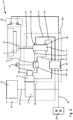
- FIG. 1 shows a first embodiment of a fluid system 1, which is part of a work machine, not shown, and which is designed for safe operation of a fluid-actuated actuator 2.
- the fluid system 1 comprises a control device 3, which is designed to provide control signals to a valve control 4 and to a working valve control 5.
- the valve control 4 is designed to control fluid control valves 6, 7.
- the working valve control 5 is designed to control working valves 8, 9.
- the working valves 8, 9 are coupled with a fluid source 10 as well as via fluid lines 11, 12 with the actuator 2. Accordingly, the working valves 8, 9 for influencing fluid flows between the fluid source 10 and the exemplary two, not shown working spaces of the actuator 2 are formed.
- an exemplary executed as an actuator of the actuator 2 piston rod 15 can be moved linearly between two unspecified end positions or optionally set in an intermediate position between the two end positions.
- the piston rod 15 is provided on the end with a punch 16, with which a workpiece 17 can be fixed to a table 18 in order to be able to carry out work operations not shown in more detail on the workpiece 17.
- the two fluid control valves 6, 7 are looped as shut-off valves in the fluid lines 11, 12 and can individually interrupt on request by the valve control fluid flow in the respective fluid line. In this way, a movement of the piston rod 15 of the actuator 2 can be prevented quickly.
- Two actuator as an end position switch, in particular as a Hall sensors, trained sensor means 19, 20 are arranged on the actuator 2, each output a sensor signal via a sensor line 21, 22 to a monitoring device 23, when the piston of the actuator 2 and not shown the piston rod 15 are located in one of the two linear end positions.
- the monitoring device 23 is connected via a signal line 24 to the valve control 4 and via a signal line 25 to a selector switch 28 designed for a mode of operation of the fluid system 1. Via the signal line 24, the monitoring device 23 can provide a monitoring signal to the valve control 4. Via the signal line 25, a selection signal from the operator switching means 28 can be provided to the monitoring device 23.
- the control device 3, the working valve control 5 and the working valves 8, 9 are in the present case designed according to a first safety category of a safety standard.
- the valve controller 4, the fluid control valves 6, 7, the sensor means 19, 20 and the monitoring device 23 form a safe working system 29, which are designed according to a second safety category of the safety standard. It is envisaged that the second safety category of the safe working system 29 within the safety standard at a higher level than the first safety category, which is provided for the control device 3, the working valve control 5 and the working valves 8, 9 is located. Accordingly, the safe working system 29 has a lower probability of failure than the control device 3.
- the monitoring device 23 is further coupled to a safety switching means in the form of a light grid 30, which is provided for securing a certain of the actuator 2, the piston rod 15 and the attached punch 16 and the table 18 hazardous area 31.
- the light grid 30 is designed such that, at least in the event that an unillustrated user or a workpiece 17 breaks through the light grid 30 during operation of the fluid system 1, it outputs a signal that can be processed by the monitoring device 23 and, if necessary, for Decommissioning of the actuator 2 leads.
- the light grid 30 serves as an access restriction in the form of access control.
- control device 3 outputs control signals to the working valve control 5 in order to effect a program-controlled actuation of the working valves 8, 9.
- control device 3 generates the control signals autonomously, that is, without requiring control commands from a higher-level machine control 32, if necessary, without being connected to the machine control 32.
- control device 3 can generate control signals, including control commands from the machine controller 32, with which the control device 3 is connected via a bus system 33, which enables bidirectional data exchange.
- the control of the working valves 8, 9 and thereby an admission of at least one of the fluid lines 11, 12 takes place with pressurized fluid.
- the pressurized fluid is thereby provided by the fluid source 10.
- an adjusting movement of the piston rod 15 of the actuator 2 between two end positions takes place by way of example, wherein in each of the two end positions the associated sensor means 19, 20 can transmit a sensor signal via the sensor lines 21, 22 to the monitoring device As soon as the not shown, connected to the piston rod 15 piston of the actuator 2 has reached the respective end position.
- An activation of the two fluid control valves 6, 7 by the valve control 4 can be provided if the fluid control valves 6, 7 are designed as normally closed (NC / normally closed) switching valves and none of the fluid flows through the fluid conduits 11, 12 of the Fluid control valves 6, 7 influenced, in particular blocked, to be. In this case, a blocking effect of the fluid control valves 6, 7 is achieved solely by switching off the control, whereby the fluid control valves 6, 7 reach the blocking position.
- the monitoring device 23 checks in knowledge of the control signals of the control device 3, whether the movement of the piston rod 15 of the actuator 2 takes place in accordance with the control signals provided. For this purpose, the monitoring device 23 checks whether the sensor signals of the two sensor means 19, 20 change within specifiable periods of time in the manner as is to be expected on the basis of the control signals. Furthermore, the monitoring device 23 checks whether the light grid 30 outputs a signal which indicates an opening of the light grid 30 by a user or a workpiece 17. If the change of the sensor signals of the sensor means. 19, 20 occurs within the predetermined time intervals and no signal from the light grid 30 is present, the monitoring device 23 determines a regular operation of the fluid system 1 and optionally outputs no monitoring signal or the normal operation of the fluid system 1 indicating monitoring signal to the valve control 4.
- the monitoring device 23 may output a monitoring signal to the valve controller 4, which is directed to the fact that an irregularity in the operation of the fluid system 1 is present.
- the monitoring device 23 may be set up such that it immediately outputs such a monitoring signal to the valve control 4 when irregularities in the fluid system 1 occur.
- the monitoring device 23 may be set up to output a monitoring signal to the valve control unit 4 only if a movement of the actuator 2 occurs at the time of determining an irregularity by the monitoring device 23 or if a movement of the actuator 2 is provided within a predefinable time segment ,
- valve control 4 Upon the arrival of a monitoring signal in the valve control 4, the valve control 4 can provide switching-off commands to the fluid control valves 6, 7 via control lines 34, 35. The fluid control valves 6, 7 then perform a blocking of the respective fluid line 11, 12 immediately after the arrival of the respective shutdown command. In this case, optionally, in particular depending on the mode of operation of the actuator 2, either the complete blockage of the fluid lines 11, 12 are provided by the valve control 4 or there is only the blocking of one of the fluid lines 11 or 12. Alternatively, a partial blockage, which is a Force limitation of the actuator has the consequence.
- the fastest and safest possible change of a movement state of the actuator 2 is achieved in order, for example, if a user interferes with the danger zone 31, a risk of injury from the actuator 2 and the components 16 operatively connected thereto To reduce 18.
- the monitoring signal from the monitoring device 23 is provided in parallel to the valve control 4 and to the control device 3, as indicated by the additional line branch 36 in the FIG. 1 is shown. It can be provided that, in the event of irregularities in the fluid system 1 and a corresponding output of a monitoring signal by the monitoring device 23 first in the control device 3 control signals are generated, which are to serve as a counter-reaction to the detected irregularity and which are transmitted via the working valve control 5 to the working valves 8, 9, for example, to cause a rapid interruption of movement of the actuator 2.
- the fluid system 1 serve the fluid control valves 6, 7 so only the change in the flow behavior, in particular the blocking of the fluid lines 11, 12 and this only if 1 irregularities are detected by the monitoring device 23 during operation of the fluid system.
- FIG. 2 illustrated embodiment of a fluid system 101 functionally identical components are provided with the same reference numerals as in the FIG. 1 , Notwithstanding the embodiment according to the FIG. 1 are in the embodiment of the fluid system 101 according to the FIG. 2 the fluid control valves 106, 107 are looped as the only valves in the respective fluid lines 111, 112 and communicate with the fluid source 10 in a communicating connection.
- control device 3 in the second embodiment of the in the FIG. 2 illustrated fluid system 101 as in the first embodiment of the in the FIG. 1 illustrated fluid system 1 according to a first safety category of a safety standard.
- the valve control 4, the fluid control valves 106, 107, the sensor means 19, 20 and the monitoring device 23 form in analogy to first embodiment according to FIG. 1 in the second embodiment according to FIG. 2 a secure work system 129, which is designed according to a second security category of the security standard, which is located at a higher level than the security category of the control device 3.
- the fluid control valves 106, 107 are used in a dual function, since they serve both in the regular operation of the fluid system 101 and in the occurrence of irregularities in the fluid system 101 for influencing the fluid flows through the fluid conduits 111, 112.
- this dual function of the fluid control valves 106, 107 can be dispensed with the working valves and the working valve control.
- this also considerably higher demands on the fluid control valves 106, 107 to make so that they still have to meet the requirements of those safety category, in which the components of the safe working system 129 are classified, and thus at. Due to the much higher load cycles in normal operation of the fluid system the construction and in the production of higher costs.
- the monitoring device is able to diagnose the correct function of the valve control and of the fluid control valves, which is also advantageous for the classification into a safety category.
- the fluid system 1 and the fluid system 101 can each be equipped with a higher-level safety circuit 37, which stands by way of example in communicating connection with the machine control 32 and with the monitoring device 23.
- the task of the safety circuit 37 is to monitor safety-relevant processes in the respective fluid system 1, 101, in particular by utilizing the sensor signals present at the monitoring device 23.
- the security circuit 37 can be set up, for example be to provide an enable signal to the monitoring device 23, if due to the received sensor signals and the control signals provided by the control device 3 and / or by the machine control 32, there is an uncritical state of the fluid system 1 or 101, in which, for example, an intervention A user can be accepted into the hazard area 31, since anyway no movement of the actuator 2 takes place or imminent.
- the output of a monitoring signal from the monitoring device 23 to the valve control 4 can be avoided in order to prevent a possible unfavorable influence on the fluid system 1 or 101, if the user intervention takes place at an uncritical time.
- an optional functional state is sought for a shutdown of the actuator 2 and a transfer of the actuator in a safe state of the fluid supply to avoid a sometimes unfavorable complete shutdown of the respective actuator 2 and consequential damage
- a sequence of several base states is provided for a shutdown of the actuator 2 or a transfer of the actuator to a safe state.
Landscapes
- Engineering & Computer Science (AREA)
- General Engineering & Computer Science (AREA)
- Mechanical Engineering (AREA)
- Physics & Mathematics (AREA)
- Fluid Mechanics (AREA)
- Fluid-Pressure Circuits (AREA)
- General Physics & Mathematics (AREA)
- Automation & Control Theory (AREA)
Claims (15)
- Système fluidique servant à faire fonctionner de manière fiable un actionneur (2) pouvant être piloté de manière fluidique, comprenant un dispositif de commande (3) servant à fournir des signaux de commande à une commande de soupape (4), comprenant une commande de soupape (4) servant à piloter des soupapes de commande de fluide (6, 7 ; 106, 107), comprenant des soupapes de commande de fluide (6, 7 ; 106, 107), qui sont reliées de manière électrique à la commande de soupape (4) et qui sont réalisées afin d'influencer des flux de fluide au niveau d'au moins un actionneur (2), comprenant des moyens de capteur (19, 20), qui sont réalisés afin de déterminer un état d'actionneur, en particulier une position d'actionneur, et afin d'émettre des signaux de capteur conformément à l'état d'actionneur déterminé, ainsi que comprenant un dispositif de surveillance (23), qui est réalisé afin de traiter les signaux de capteur et afin de fournir à la commande de soupape (4) un signal de surveillance, caractérisé en ce que le dispositif de commande (3) est réalisé selon une première catégorie de sécurité d'une norme de sécurité, et que la commande de soupape (4), les soupapes de commande de fluide (6, 7 ; 106, 107), les moyens de capteur (19, 20) et le dispositif de surveillance (23) forment un système de travail (29; 129) fiable et sont réalisés selon une deuxième catégorie de sécurité de la norme de sécurité, dans lequel la deuxième catégorie de sécurité se situe à un niveau plus élevé que la première catégorie de sécurité au sein de la norme de sécurité.
- Système fluidique selon la revendication 1, caractérisé en ce que le dispositif de surveillance (23) est relié de manière électrique à un moyen de commutation de sécurité (30) et est réalisé en vue d'une intégration d'un signal de sécurité du moyen de commutation de sécurité (30) dans le signal de surveillance, dans lequel le moyen de commutation de sécurité (30) est réalisé sous la forme d'une limitation d'accès et/ou de surveillance d'accès à une zone dangereuse (31) définie par l'actionneur (2), en particulier sous la forme d'une barrière lumineuse ou sous la forme d'un tapis de commutation de marche ou sous la forme d'un contact de porte d'une porte de maintenance dans une cage de sécurité.
- Système fluidique selon la revendication 1 ou 2, caractérisé en ce que le dispositif de surveillance (23) est relié de manière électrique à un moyen de commutation d'utilisateur (28) et/ou à un circuit de sécurité (37) et est réalisé en vue d'une intégration d'un signal d'utilisation du moyen de commutation d'utilisateur (28) et/ou d'un signal de déblocage du circuit de sécurité (37) dans le signal de surveillance, dans lequel le moyen de commutation d'utilisateur (28) est réalisé sous la forme d'un commutateur sélectif pour un type de fonctionnement du système fluidique (1 ; 101) et dans lequel le circuit de sécurité (37) est réalisé sous la forme d'un système de surveillance, qui peut exécuter également des fonctions de commande, pour le système fluidique (1 ; 101).
- Système fluidique selon la revendication 2 ou 3, caractérisé en ce que le dispositif de commande (3) est relié de manière électrique au moyen de commutation de sécurité (30) et/ou au moyen de commutation d'utilisateur (28) et est réalisé en vue d'une intégration d'un signal du moyen de commutation de sécurité (30) et/ou du moyen de commutation d'utilisateur (28) lors de la génération d'instructions de commande à une commande de soupape de travail (5) servant à piloter des soupapes de travail (8, 9), qui peuvent être reliées à l'actionneur (2), et/ou à la commande de soupape (4).
- Système fluidique selon l'une quelconque des revendications précédentes, caractérisé en ce que le dispositif de soupape (4) ou le système de travail (29 ; 129) fiable est mis au point afin de piloter les soupapes de commande de fluide (6, 7 ; 106, 107) de telle manière que des flux de fluide au niveau de l'au moins un actionneur (2) sont influencés de telle manière que l'actionneur (2) peut être amené, dans un laps de temps pouvant être spécifié, dans au moins un état de fonction pouvant être spécifié choisi parmi le groupe suivant : actionneur (2) sans pression ; flux de fluide depuis et/ou vers l'actionneur (2) stoppés ; spécification de direction de déplacement pour l'actionneur (2) ; actionneur (2) régulé sur arrêt ; actionneur (2) régulé sur une force spécifiée ; pression dans l'actionneur (2) à limitation non régulée ; serrage d'actionneur activé ; vitesse de déplacement de l'actionneur (2) limitée.
- Système fluidique selon la revendication 5, caractérisé en ce que la commande de soupape (4) ou le système de travail (29 ; 129) fiable est mise ou mis au point afin de spécifier une succession dans le temps d'au moins deux états de fonction.
- Système fluidique selon l'une quelconque des revendications précédentes, caractérisé en ce que les soupapes de commande de fluide (6, 7 ; 106, 107) pour une commande de fluide de l'actionneur (2) peuvent être intercalées sous la forme de soupapes de commutation (106, 107) entre une source de fluide (10) et l'actionneur (2) ou peuvent être intercalées en amont ou en aval de soupapes de travail (8, 9), qui peuvent être pilotées par le dispositif de commande (3), sous la forme de soupapes de fermeture (6, 7) entre la source de fluide (10) et l'actionneur (2) afin de garantir un déplacement de réglage d'un organe de réglage (15) de l'actionneur (2) dans une position de commutation pouvant être spécifiée ou un maintien de l'organe de réglage (15) de l'actionneur dans la position de commutation pouvant être spécifiée, et/ou que le dispositif de commande (3) est réalisé en vue d'une communication bidirectionnelle, en particulier par l'intermédiaire d'un système de bus de terrain (33), avec une commande de machine ou de processus (32) maître, qui est à affecter à une catégorie de sécurité identique ou inférieure ou supérieure à celle du dispositif de commande (3).
- Procédé servant à faire fonctionner un système fluidique selon l'une quelconque des revendications précédentes, caractérisé par les étapes suivantes consistant à : déterminer l'état d'actionneur avec des moyens de capteur (19, 20) et émettre de signaux de capteur conformément à l'état d'actionneur déterminé à l'attention du dispositif de surveillance (23) ; traiter les signaux de capteur dans le dispositif de surveillance (23) et fournir un signal de surveillance à la commande de soupape (4) au moins dans les cas où aucun signal de détecteur n'est fourni par les moyens de capteur (19, 20) ou des signaux de capteur erronés sont fournis par les moyens de capteur (19, 20) ; traiter le signal de surveillance dans la commande de soupape (4), en particulier en fonction des signaux de capteur déterminés ; et piloter les soupapes de commande de fluide (6, 7 ; 106, 107) servant à influencer au moins un flux de fluide au niveau de l'actionneur (2) de sorte que l'actionneur (2) adopte et/ou conserve un état pouvant être spécifié, fiable.
- Procédé selon la revendication 8, caractérisé en ce que le dispositif de surveillance (23) surveille des signaux électriques d'un moyen de commutation de sécurité (30) et fournit un signal de surveillance correspondant à la commande de soupape (4) lors d'une intervention ou d'un accès dans ou à une zone dangereuse (31) définie par l'actionneur (2) afin de piloter les soupapes de commande de fluide (6, 7 ; 106, 107) de telle manière qu'au moins un flux de fluide au niveau de l'actionneur (2) est influencé de telle manière que l'actionneur (2) adopte et/ou conserve un état pouvant être spécifié, fiable.
- Procédé selon la revendication 9, caractérisé en ce que le dispositif de surveillance (23) fournit, lors de la détection d'une intervention ou d'un accès dans ou à une zone dangereuse (31) définie par l'actionneur (2), à l'aide du signal du moyen de commutation de sécurité (30), alors seulement un signal de surveillance correspondant à la commande de soupape (4) quand une modification d'état imminente de l'actionneur (2) est déterminée à l'aide d'une émission d'un signal de commande du dispositif de commande (3) et/ou de la commande de soupape (4) et/ou une modification d'état de l'actionneur (2) est détectée à l'aide d'au moins une modification d'un signal de capteur d'au moins un des moyens de capteur (18, 19).
- Procédé selon la revendication 10, caractérisé en ce que le dispositif de surveillance (23) règle la mise à disposition du signal de surveillance dès qu'aucune intervention ou accès dans ou à une zone dangereuse (31) définie par l'actionneur (2) n'est plus détectée ou détecté, et que la commande de soupape (4) ne réalise en l'absence d'un signal de surveillance aucun pilotage des soupapes de commande de fluide (6, 7 ; 106, 107) divergeant d'une spécification par le dispositif de commande (3).
- Procédé selon la revendication 8, 9 ou 10, caractérisé en ce que la commande de soupape (4) pilote de telle manière les soupapes de commande de fluide (6, 7 ; 106, 107) qu'au moins un espace de travail dans l'actionneur (2) reste alimenté en fluide soumis à l'action d'une pression en présence d'un signal de surveillance correspondant.
- Procédé selon la revendication 8, caractérisé en ce que le dispositif de surveillance (23) surveille des signaux électriques d'un moyen de commutation d'utilisateur (28) et adapte le signal de surveillance à la commande de soupape (4) en fonction des signaux déterminés du moyen de commutation d'utilisateur (28).
- Procédé selon l'une quelconque des revendications 9 à 13, caractérisé en ce que des signaux de commande de la commande de soupape (4) qui servent à piloter les soupapes de commande de fluide (6, 7 ; 106, 107) et des signaux de capteur des moyens de capteur (19, 20), qui sont déterminés au niveau de l'actionneur (2), sont traités dans le dispositif de surveillance (23) afin de permettre une surveillance de l'aptitude au fonctionnement du système de travail (29; 129) fiable, et/ou que la commande de soupape (4) ou le système de travail (29; 129) fiable réalise afin d'atteindre l'état fiable un pilotage des soupapes de commande de fluide (6, 7 ; 106, 107) de telle manière que des flux de fluide au niveau de l'au moins un actionneur (2) sont influencés de telle manière que l'actionneur (2) peut être amené, dans un laps de temps pouvant être spécifié, dans au moins un état de fonction pouvant être spécifié choisi parmi le groupe suivant : actionneur (2) sans pression ; flux de fluide depuis et/ou vers l'actionneur (2) stoppés ; spécification de direction de déplacement pour l'actionneur (2) ; actionneur (2) régulé sur arrêt ; actionneur (2) régulé sur une force spécifiée ; pression dans l'actionneur (2) limitée ; serrage d'actionneur activé ; vitesse de déplacement de l'actionneur (2) limitée.
- Procédé selon la revendication 14, caractérisé en ce qu'une succession dans le temps d'au moins deux états de fonction est spécifiée par la commande de soupape (4) ou par le système de travail (29 ; 129) fiable.
Applications Claiming Priority (2)
| Application Number | Priority Date | Filing Date | Title |
|---|---|---|---|
| DE102012005224A DE102012005224A1 (de) | 2012-03-15 | 2012-03-15 | Fluidsystem und Verfahren zum Betreiben eines Fluidsystems |
| PCT/EP2013/000762 WO2013135382A1 (fr) | 2012-03-15 | 2013-03-14 | Système fluidique et procédé permettant de faire fonctionner un système fluidique |
Publications (2)
| Publication Number | Publication Date |
|---|---|
| EP2836724A1 EP2836724A1 (fr) | 2015-02-18 |
| EP2836724B1 true EP2836724B1 (fr) | 2017-08-23 |
Family
ID=47891597
Family Applications (1)
| Application Number | Title | Priority Date | Filing Date |
|---|---|---|---|
| EP13709779.6A Not-in-force EP2836724B1 (fr) | 2012-03-15 | 2013-03-14 | Système fluidique et métode |
Country Status (5)
| Country | Link |
|---|---|
| US (1) | US10303145B2 (fr) |
| EP (1) | EP2836724B1 (fr) |
| CN (1) | CN104285067B (fr) |
| DE (1) | DE102012005224A1 (fr) |
| WO (1) | WO2013135382A1 (fr) |
Families Citing this family (7)
| Publication number | Priority date | Publication date | Assignee | Title |
|---|---|---|---|---|
| MX2019010737A (es) | 2017-03-07 | 2020-01-20 | Asco Lp | Un dispositivo y metodo para la falla anticipada en una valvula de solenoide para un conjunto de colector. |
| DE102017215461A1 (de) * | 2017-09-04 | 2019-03-07 | Krones Ag | Verfahren zur Leckage-Erkennung in einer Vorrichtung zum Umformen von Behälter-Vorformlingen |
| US11408450B2 (en) | 2017-09-18 | 2022-08-09 | Asco, L.P. | Device and method for monitoring response time in a valve manifold assembly |
| US11592376B2 (en) | 2018-11-30 | 2023-02-28 | Illinois Tool Works Inc. | Safety systems and material testing systems including safety systems |
| DE102019204167B4 (de) * | 2019-03-26 | 2021-10-21 | Festo Se & Co. Kg | Assistenzvorrichtung und Verfahren zum Betreiben einer Assistenzvorrichtung |
| DE102019217743A1 (de) * | 2019-11-18 | 2021-05-20 | Festo Se & Co. Kg | Fluidanordnung |
| DE102021110456B4 (de) * | 2021-04-23 | 2024-07-25 | Bürkert Werke GmbH & Co. KG | Sicherheitsmodul für ein Prozessventil und System |
Family Cites Families (16)
| Publication number | Priority date | Publication date | Assignee | Title |
|---|---|---|---|---|
| GB1556013A (en) * | 1978-04-19 | 1979-11-14 | Carrier Drysys Ltd | Paint spraying apparatus |
| US4903529A (en) * | 1988-10-07 | 1990-02-27 | Westinghouse Electric Corp. | Valve system analyzer |
| CN2083741U (zh) * | 1990-01-20 | 1991-08-28 | 山西矿业学院 | 液压支架安全阀动态特性试验装置 |
| US6037857A (en) * | 1997-06-06 | 2000-03-14 | Allen-Bradley Company, Llc | Serial data isolator industrial control system providing intrinsically safe operation |
| DE19927372C2 (de) | 1999-06-16 | 2003-06-18 | Eads Deutschland Gmbh | Verfahren und Vorrichtung zum Erkennen einer Fehlfunktion von Stellantrieben |
| DE19942509A1 (de) * | 1999-09-07 | 2001-04-05 | Festo Ag & Co | Verfahren und Vorrichtung zur Versorgung von elektrischen Verbrauchern in oder an einer pneumatischen Vorrichtung mit elektrischer Versorgungsenergie |
| DE10006367A1 (de) * | 2000-02-12 | 2001-08-16 | Festo Ag & Co | Fluidtechnisches System mit Sicherheitsfunktion |
| DE20208992U1 (de) * | 2002-06-10 | 2003-10-23 | HAWE Hydraulik GmbH & Co. KG, 81673 München | Elektrohydraulische Spannvorrichtung |
| CN1180233C (zh) * | 2002-09-19 | 2004-12-15 | 北京航空航天大学 | 液压能源装置 |
| DK1747380T3 (da) * | 2004-04-16 | 2011-09-26 | Festo Ag & Co Kg | Fremgangsmåde til indgrænsning af fejl og diagnose i et fluidanlæg |
| DE102004052602B4 (de) * | 2004-10-29 | 2008-03-27 | Sauer-Danfoss Aps | Ventilanordnung |
| JP4707717B2 (ja) * | 2004-11-19 | 2011-06-22 | フェスト アクツィエンゲゼルシャフト ウント コー | 少なくとも1つの空気弁アクチュエータ装置のための診断装置 |
| KR100641393B1 (ko) * | 2004-12-07 | 2006-11-01 | 볼보 컨스트럭션 이키프먼트 홀딩 스웨덴 에이비 | 유압제어회로 및 유압제어방법 |
| DE102007038611A1 (de) * | 2007-08-16 | 2009-02-19 | Festo Ag & Co. Kg | Ventilmodul |
| US8365762B1 (en) * | 2010-01-14 | 2013-02-05 | Air Tractors, Inc. | Hydraulic control system |
| JP5924134B2 (ja) * | 2012-05-30 | 2016-05-25 | セイコーエプソン株式会社 | 侵入検出装置,ロボットシステム,侵入検出方法および侵入検出プログラム |
-
2012
- 2012-03-15 DE DE102012005224A patent/DE102012005224A1/de not_active Withdrawn
-
2013
- 2013-03-14 CN CN201380014406.9A patent/CN104285067B/zh not_active Expired - Fee Related
- 2013-03-14 EP EP13709779.6A patent/EP2836724B1/fr not_active Not-in-force
- 2013-03-14 WO PCT/EP2013/000762 patent/WO2013135382A1/fr not_active Ceased
- 2013-03-14 US US14/384,998 patent/US10303145B2/en active Active
Non-Patent Citations (1)
| Title |
|---|
| None * |
Also Published As
| Publication number | Publication date |
|---|---|
| US20150285281A1 (en) | 2015-10-08 |
| EP2836724A1 (fr) | 2015-02-18 |
| DE102012005224A1 (de) | 2013-09-19 |
| US10303145B2 (en) | 2019-05-28 |
| WO2013135382A1 (fr) | 2013-09-19 |
| CN104285067B (zh) | 2016-09-28 |
| CN104285067A (zh) | 2015-01-14 |
Similar Documents
| Publication | Publication Date | Title |
|---|---|---|
| EP2836724B1 (fr) | Système fluidique et métode | |
| EP1266147B1 (fr) | Systeme fluidique a fonction de securite | |
| EP2202592B1 (fr) | Dispositif de sécurité destiné à la commande à plusieurs canaux d'un dispositif de sécurité | |
| DE102014013098B3 (de) | Stellungsregler für ein pneumatisches Stellgerät | |
| EP2907626B1 (fr) | Procédé et dispositif d'immobilisation d'un axe de manipulateur | |
| EP2545417B1 (fr) | Procédé de remplacement d'un équipement de conduction existant dans un système d'automatisation par un nouvel équipement de conduction et système d'automatisation ainsi construit | |
| WO2006103249A2 (fr) | Procede et dispositif de commande pour la reaction ciblee en cas de contact entre un element d'une machine et un objet | |
| DE102013013875A1 (de) | Verfahren zum Steuern eines Roboters | |
| WO2017178413A1 (fr) | Circuit de commande électrohydraulique pour manipulateur de grande taille | |
| EP1834220B1 (fr) | Dispositif de soupape electrohydraulique redondant | |
| EP3137948B1 (fr) | Dispositif et procédé de surveillance d'une partie de machine mobile avec protection contre les erreurs | |
| WO2010066318A1 (fr) | Procédé et dispositif de commande d'un système de manipulateur | |
| DE10233873B4 (de) | Steuerung für eine Krananlage, insbesondere einen Containerkran | |
| EP3592991B1 (fr) | Procédé pour la commande d'un actionneur hydraulique, dispositif de commande et commande d'actionneur | |
| EP2276935B1 (fr) | Dispositif et procede de commande pour une soupape a fermeture rapide d'une turbine a vapeur | |
| EP2154587B1 (fr) | Système de positionnement d'un actionneur | |
| DE102011087684A1 (de) | Hydraulisches Kupplungssystem | |
| DE102024111081B4 (de) | Ventilanordnung | |
| EP2159658A1 (fr) | Procédé et contrôleur d'automatisation destinés à l'émission d'une information de maintenance d'un composant d'automatisation | |
| EP2916182A1 (fr) | Module de commande de sécurité et dispositif de commande pour une machine de traitement à entraînement fluidique | |
| DE102008008449A1 (de) | Elektrische Presse | |
| DE102016222940B4 (de) | Sicherheitsmodul für ein Automatisierungssystem, Automatisierungssystem und Verfahren zum Betreiben eines Sicherheitsmoduls in einem Automatisierungssystem | |
| WO2021123029A1 (fr) | Procédé de test de la fonctionnalité d'une électrovanne pour le déclenchement d'une soupape de sécurité | |
| DE102012012047A1 (de) | Antriebsregler und Verfahren zur Stillsetzung einer Achse | |
| EP3792716B1 (fr) | Commande numérique pourvue de mise en mémoire tampon des valeurs de consigne de position |
Legal Events
| Date | Code | Title | Description |
|---|---|---|---|
| PUAI | Public reference made under article 153(3) epc to a published international application that has entered the european phase |
Free format text: ORIGINAL CODE: 0009012 |
|
| 17P | Request for examination filed |
Effective date: 20141001 |
|
| AK | Designated contracting states |
Kind code of ref document: A1 Designated state(s): AL AT BE BG CH CY CZ DE DK EE ES FI FR GB GR HR HU IE IS IT LI LT LU LV MC MK MT NL NO PL PT RO RS SE SI SK SM TR |
|
| AX | Request for extension of the european patent |
Extension state: BA ME |
|
| DAX | Request for extension of the european patent (deleted) | ||
| GRAP | Despatch of communication of intention to grant a patent |
Free format text: ORIGINAL CODE: EPIDOSNIGR1 |
|
| INTG | Intention to grant announced |
Effective date: 20170410 |
|
| GRAS | Grant fee paid |
Free format text: ORIGINAL CODE: EPIDOSNIGR3 |
|
| GRAA | (expected) grant |
Free format text: ORIGINAL CODE: 0009210 |
|
| AK | Designated contracting states |
Kind code of ref document: B1 Designated state(s): AL AT BE BG CH CY CZ DE DK EE ES FI FR GB GR HR HU IE IS IT LI LT LU LV MC MK MT NL NO PL PT RO RS SE SI SK SM TR |
|
| REG | Reference to a national code |
Ref country code: GB Ref legal event code: FG4D Free format text: NOT ENGLISH |
|
| REG | Reference to a national code |
Ref country code: CH Ref legal event code: EP |
|
| REG | Reference to a national code |
Ref country code: AT Ref legal event code: REF Ref document number: 921664 Country of ref document: AT Kind code of ref document: T Effective date: 20170915 |
|
| REG | Reference to a national code |
Ref country code: IE Ref legal event code: FG4D Free format text: LANGUAGE OF EP DOCUMENT: GERMAN |
|
| REG | Reference to a national code |
Ref country code: DE Ref legal event code: R096 Ref document number: 502013008138 Country of ref document: DE |
|
| REG | Reference to a national code |
Ref country code: NL Ref legal event code: MP Effective date: 20170823 |
|
| REG | Reference to a national code |
Ref country code: LT Ref legal event code: MG4D |
|
| PG25 | Lapsed in a contracting state [announced via postgrant information from national office to epo] |
Ref country code: NO Free format text: LAPSE BECAUSE OF FAILURE TO SUBMIT A TRANSLATION OF THE DESCRIPTION OR TO PAY THE FEE WITHIN THE PRESCRIBED TIME-LIMIT Effective date: 20171123 Ref country code: SE Free format text: LAPSE BECAUSE OF FAILURE TO SUBMIT A TRANSLATION OF THE DESCRIPTION OR TO PAY THE FEE WITHIN THE PRESCRIBED TIME-LIMIT Effective date: 20170823 Ref country code: HR Free format text: LAPSE BECAUSE OF FAILURE TO SUBMIT A TRANSLATION OF THE DESCRIPTION OR TO PAY THE FEE WITHIN THE PRESCRIBED TIME-LIMIT Effective date: 20170823 Ref country code: NL Free format text: LAPSE BECAUSE OF FAILURE TO SUBMIT A TRANSLATION OF THE DESCRIPTION OR TO PAY THE FEE WITHIN THE PRESCRIBED TIME-LIMIT Effective date: 20170823 Ref country code: FI Free format text: LAPSE BECAUSE OF FAILURE TO SUBMIT A TRANSLATION OF THE DESCRIPTION OR TO PAY THE FEE WITHIN THE PRESCRIBED TIME-LIMIT Effective date: 20170823 Ref country code: LT Free format text: LAPSE BECAUSE OF FAILURE TO SUBMIT A TRANSLATION OF THE DESCRIPTION OR TO PAY THE FEE WITHIN THE PRESCRIBED TIME-LIMIT Effective date: 20170823 |
|
| PG25 | Lapsed in a contracting state [announced via postgrant information from national office to epo] |
Ref country code: PL Free format text: LAPSE BECAUSE OF FAILURE TO SUBMIT A TRANSLATION OF THE DESCRIPTION OR TO PAY THE FEE WITHIN THE PRESCRIBED TIME-LIMIT Effective date: 20170823 Ref country code: BG Free format text: LAPSE BECAUSE OF FAILURE TO SUBMIT A TRANSLATION OF THE DESCRIPTION OR TO PAY THE FEE WITHIN THE PRESCRIBED TIME-LIMIT Effective date: 20171123 Ref country code: ES Free format text: LAPSE BECAUSE OF FAILURE TO SUBMIT A TRANSLATION OF THE DESCRIPTION OR TO PAY THE FEE WITHIN THE PRESCRIBED TIME-LIMIT Effective date: 20170823 Ref country code: IS Free format text: LAPSE BECAUSE OF FAILURE TO SUBMIT A TRANSLATION OF THE DESCRIPTION OR TO PAY THE FEE WITHIN THE PRESCRIBED TIME-LIMIT Effective date: 20171223 Ref country code: RS Free format text: LAPSE BECAUSE OF FAILURE TO SUBMIT A TRANSLATION OF THE DESCRIPTION OR TO PAY THE FEE WITHIN THE PRESCRIBED TIME-LIMIT Effective date: 20170823 Ref country code: LV Free format text: LAPSE BECAUSE OF FAILURE TO SUBMIT A TRANSLATION OF THE DESCRIPTION OR TO PAY THE FEE WITHIN THE PRESCRIBED TIME-LIMIT Effective date: 20170823 Ref country code: GR Free format text: LAPSE BECAUSE OF FAILURE TO SUBMIT A TRANSLATION OF THE DESCRIPTION OR TO PAY THE FEE WITHIN THE PRESCRIBED TIME-LIMIT Effective date: 20171124 |
|
| REG | Reference to a national code |
Ref country code: FR Ref legal event code: PLFP Year of fee payment: 6 |
|
| PG25 | Lapsed in a contracting state [announced via postgrant information from national office to epo] |
Ref country code: RO Free format text: LAPSE BECAUSE OF FAILURE TO SUBMIT A TRANSLATION OF THE DESCRIPTION OR TO PAY THE FEE WITHIN THE PRESCRIBED TIME-LIMIT Effective date: 20170823 Ref country code: DK Free format text: LAPSE BECAUSE OF FAILURE TO SUBMIT A TRANSLATION OF THE DESCRIPTION OR TO PAY THE FEE WITHIN THE PRESCRIBED TIME-LIMIT Effective date: 20170823 Ref country code: CZ Free format text: LAPSE BECAUSE OF FAILURE TO SUBMIT A TRANSLATION OF THE DESCRIPTION OR TO PAY THE FEE WITHIN THE PRESCRIBED TIME-LIMIT Effective date: 20170823 |
|
| REG | Reference to a national code |
Ref country code: DE Ref legal event code: R097 Ref document number: 502013008138 Country of ref document: DE |
|
| PG25 | Lapsed in a contracting state [announced via postgrant information from national office to epo] |
Ref country code: EE Free format text: LAPSE BECAUSE OF FAILURE TO SUBMIT A TRANSLATION OF THE DESCRIPTION OR TO PAY THE FEE WITHIN THE PRESCRIBED TIME-LIMIT Effective date: 20170823 Ref country code: SK Free format text: LAPSE BECAUSE OF FAILURE TO SUBMIT A TRANSLATION OF THE DESCRIPTION OR TO PAY THE FEE WITHIN THE PRESCRIBED TIME-LIMIT Effective date: 20170823 Ref country code: SM Free format text: LAPSE BECAUSE OF FAILURE TO SUBMIT A TRANSLATION OF THE DESCRIPTION OR TO PAY THE FEE WITHIN THE PRESCRIBED TIME-LIMIT Effective date: 20170823 |
|
| PLBE | No opposition filed within time limit |
Free format text: ORIGINAL CODE: 0009261 |
|
| STAA | Information on the status of an ep patent application or granted ep patent |
Free format text: STATUS: NO OPPOSITION FILED WITHIN TIME LIMIT |
|
| 26N | No opposition filed |
Effective date: 20180524 |
|
| PG25 | Lapsed in a contracting state [announced via postgrant information from national office to epo] |
Ref country code: SI Free format text: LAPSE BECAUSE OF FAILURE TO SUBMIT A TRANSLATION OF THE DESCRIPTION OR TO PAY THE FEE WITHIN THE PRESCRIBED TIME-LIMIT Effective date: 20170823 |
|
| PG25 | Lapsed in a contracting state [announced via postgrant information from national office to epo] |
Ref country code: MT Free format text: LAPSE BECAUSE OF FAILURE TO SUBMIT A TRANSLATION OF THE DESCRIPTION OR TO PAY THE FEE WITHIN THE PRESCRIBED TIME-LIMIT Effective date: 20170823 |
|
| REG | Reference to a national code |
Ref country code: CH Ref legal event code: PL |
|
| PG25 | Lapsed in a contracting state [announced via postgrant information from national office to epo] |
Ref country code: MC Free format text: LAPSE BECAUSE OF FAILURE TO SUBMIT A TRANSLATION OF THE DESCRIPTION OR TO PAY THE FEE WITHIN THE PRESCRIBED TIME-LIMIT Effective date: 20170823 |
|
| REG | Reference to a national code |
Ref country code: BE Ref legal event code: MM Effective date: 20180331 |
|
| REG | Reference to a national code |
Ref country code: IE Ref legal event code: MM4A |
|
| PG25 | Lapsed in a contracting state [announced via postgrant information from national office to epo] |
Ref country code: LU Free format text: LAPSE BECAUSE OF NON-PAYMENT OF DUE FEES Effective date: 20180314 |
|
| PG25 | Lapsed in a contracting state [announced via postgrant information from national office to epo] |
Ref country code: IE Free format text: LAPSE BECAUSE OF NON-PAYMENT OF DUE FEES Effective date: 20180314 |
|
| PG25 | Lapsed in a contracting state [announced via postgrant information from national office to epo] |
Ref country code: CH Free format text: LAPSE BECAUSE OF NON-PAYMENT OF DUE FEES Effective date: 20180331 Ref country code: BE Free format text: LAPSE BECAUSE OF NON-PAYMENT OF DUE FEES Effective date: 20180331 Ref country code: LI Free format text: LAPSE BECAUSE OF NON-PAYMENT OF DUE FEES Effective date: 20180331 |
|
| PGFP | Annual fee paid to national office [announced via postgrant information from national office to epo] |
Ref country code: IE Payment date: 20190311 Year of fee payment: 7 Ref country code: IT Payment date: 20190321 Year of fee payment: 7 Ref country code: FR Payment date: 20190326 Year of fee payment: 7 |
|
| REG | Reference to a national code |
Ref country code: AT Ref legal event code: MM01 Ref document number: 921664 Country of ref document: AT Kind code of ref document: T Effective date: 20180314 |
|
| PG25 | Lapsed in a contracting state [announced via postgrant information from national office to epo] |
Ref country code: AT Free format text: LAPSE BECAUSE OF NON-PAYMENT OF DUE FEES Effective date: 20180314 |
|
| REG | Reference to a national code |
Ref country code: DE Ref legal event code: R082 Ref document number: 502013008138 Country of ref document: DE Representative=s name: PATENTANWAELTE MAGENBAUER & KOLLEGEN PARTNERSC, DE Ref country code: DE Ref legal event code: R081 Ref document number: 502013008138 Country of ref document: DE Owner name: FESTO SE & CO. KG, DE Free format text: FORMER OWNER: FESTO AG & CO. KG, 73734 ESSLINGEN, DE Ref country code: DE Ref legal event code: R081 Ref document number: 502013008138 Country of ref document: DE Owner name: FESTO AG & CO. KG, DE Free format text: FORMER OWNER: FESTO AG & CO. KG, 73734 ESSLINGEN, DE |
|
| PG25 | Lapsed in a contracting state [announced via postgrant information from national office to epo] |
Ref country code: TR Free format text: LAPSE BECAUSE OF FAILURE TO SUBMIT A TRANSLATION OF THE DESCRIPTION OR TO PAY THE FEE WITHIN THE PRESCRIBED TIME-LIMIT Effective date: 20170823 |
|
| PG25 | Lapsed in a contracting state [announced via postgrant information from national office to epo] |
Ref country code: PT Free format text: LAPSE BECAUSE OF FAILURE TO SUBMIT A TRANSLATION OF THE DESCRIPTION OR TO PAY THE FEE WITHIN THE PRESCRIBED TIME-LIMIT Effective date: 20170823 |
|
| PG25 | Lapsed in a contracting state [announced via postgrant information from national office to epo] |
Ref country code: HU Free format text: LAPSE BECAUSE OF FAILURE TO SUBMIT A TRANSLATION OF THE DESCRIPTION OR TO PAY THE FEE WITHIN THE PRESCRIBED TIME-LIMIT; INVALID AB INITIO Effective date: 20130314 Ref country code: CY Free format text: LAPSE BECAUSE OF FAILURE TO SUBMIT A TRANSLATION OF THE DESCRIPTION OR TO PAY THE FEE WITHIN THE PRESCRIBED TIME-LIMIT Effective date: 20170823 Ref country code: MK Free format text: LAPSE BECAUSE OF NON-PAYMENT OF DUE FEES Effective date: 20170823 |
|
| PG25 | Lapsed in a contracting state [announced via postgrant information from national office to epo] |
Ref country code: AL Free format text: LAPSE BECAUSE OF FAILURE TO SUBMIT A TRANSLATION OF THE DESCRIPTION OR TO PAY THE FEE WITHIN THE PRESCRIBED TIME-LIMIT Effective date: 20170823 |
|
| PG25 | Lapsed in a contracting state [announced via postgrant information from national office to epo] |
Ref country code: FR Free format text: LAPSE BECAUSE OF NON-PAYMENT OF DUE FEES Effective date: 20200331 |
|
| GBPC | Gb: european patent ceased through non-payment of renewal fee |
Effective date: 20200314 |
|
| PG25 | Lapsed in a contracting state [announced via postgrant information from national office to epo] |
Ref country code: GB Free format text: LAPSE BECAUSE OF NON-PAYMENT OF DUE FEES Effective date: 20200314 |
|
| PG25 | Lapsed in a contracting state [announced via postgrant information from national office to epo] |
Ref country code: IT Free format text: LAPSE BECAUSE OF NON-PAYMENT OF DUE FEES Effective date: 20200314 |
|
| PGFP | Annual fee paid to national office [announced via postgrant information from national office to epo] |
Ref country code: DE Payment date: 20220621 Year of fee payment: 11 |
|
| REG | Reference to a national code |
Ref country code: DE Ref legal event code: R119 Ref document number: 502013008138 Country of ref document: DE |
|
| PG25 | Lapsed in a contracting state [announced via postgrant information from national office to epo] |
Ref country code: DE Free format text: LAPSE BECAUSE OF NON-PAYMENT OF DUE FEES Effective date: 20241001 |
|
| PG25 | Lapsed in a contracting state [announced via postgrant information from national office to epo] |
Ref country code: DE Free format text: LAPSE BECAUSE OF NON-PAYMENT OF DUE FEES Effective date: 20241001 |