EP2836802B1 - Appareil de mesure du niveau de remplissage - Google Patents
Appareil de mesure du niveau de remplissage Download PDFInfo
- Publication number
- EP2836802B1 EP2836802B1 EP13711024.3A EP13711024A EP2836802B1 EP 2836802 B1 EP2836802 B1 EP 2836802B1 EP 13711024 A EP13711024 A EP 13711024A EP 2836802 B1 EP2836802 B1 EP 2836802B1
- Authority
- EP
- European Patent Office
- Prior art keywords
- locking element
- level transmitter
- locking
- vibration
- previous
- Prior art date
- Legal status (The legal status is an assumption and is not a legal conclusion. Google has not performed a legal analysis and makes no representation as to the accuracy of the status listed.)
- Active
Links
Images
Classifications
-
- G—PHYSICS
- G01—MEASURING; TESTING
- G01F—MEASURING VOLUME, VOLUME FLOW, MASS FLOW OR LIQUID LEVEL; METERING BY VOLUME
- G01F23/00—Indicating or measuring liquid level or level of fluent solid material, e.g. indicating in terms of volume or indicating by means of an alarm
- G01F23/22—Indicating or measuring liquid level or level of fluent solid material, e.g. indicating in terms of volume or indicating by means of an alarm by measuring physical variables, other than linear dimensions, pressure or weight, dependent on the level to be measured, e.g. by difference of heat transfer of steam or water
- G01F23/28—Indicating or measuring liquid level or level of fluent solid material, e.g. indicating in terms of volume or indicating by means of an alarm by measuring physical variables, other than linear dimensions, pressure or weight, dependent on the level to be measured, e.g. by difference of heat transfer of steam or water by measuring the variations of parameters of electromagnetic or acoustic waves applied directly to the liquid or fluent solid material
- G01F23/296—Acoustic waves
- G01F23/2966—Acoustic waves making use of acoustical resonance or standing waves
- G01F23/2967—Acoustic waves making use of acoustical resonance or standing waves for discrete levels
Definitions
- the present invention relates to a level measuring device with a vibration system, which has at least one outer tubular vibrating element and an inner vibrating element, wherein the outer vibrating element surrounds the inner vibrating element coaxially at least in sections.
- Such level gauges are also known as the single rod.
- the level gauge is used to detect a level of a medium, in particular a bulk material, in a container.
- the level gauge is used as a level switch for monitoring a predetermined maximum or minimum level.
- the inner oscillating rod has a compensation mass, which is displaceably arranged so that the resonant frequency of the inner oscillatory structure can be adapted to that of the outer oscillatory structure.
- the compensation mass is for example attached to an axially extending rod which has a screw thread. A motor rotates the rod such that the compensation mass moves in the axial direction.
- a level measuring device which also has two mutually arranged tubular vibration body.
- the outer vibrating body is over a elastic portion attached to a fastening device.
- a balancing body is arranged inside the inner oscillating body.
- the balancing body is configured elastically in sections and introduced under compression in the inner oscillating body.
- the balancing body has a section with an external thread, which is matched to an internal thread in the inner wall of the inner oscillating body.
- a slot is formed on the front side, in which an adjusting instrument, for example a screwdriver, can engage. The adjustment is done manually or via a motor drive control.
- a manual adjustment of the balance body on the rod-shaped adjustment is uncomfortable.
- a motor control is expensive to implement.
- the oscillating system described is relatively expensive due to the thread in the production.
- the object of the invention is to provide a level gauge with a readily adjustable adjustment body.
- the object is achieved in that in an inner space of the inner vibrating element displaceable in the axial direction compensation device is arranged with at least a first locking element, a second locking element and a coupling element, wherein the locking elements and the coupling element consist of a piezoelectric material, wherein the coupling element the connecting the first locking element and the second locking element to each other, and wherein the first locking element and the second locking element are in each case in a rest state in each case frictionally in communication with a wall of the interior, and in that the level measuring device has an electronic unit, which is adapted to the compensation device by means of electrical signals to be positioned at a predeterminable position. Due to the displacement of the compensation device in the inner oscillating element an energetic imbalance can be compensated, which arises, for example, by formation of deposits on the outer oscillating element or corrosion.
- an additional mass is attached to the first locking element and / or the second locking element.
- the inner vibrating element is at least partially tubular.
- the compensation device is designed to move in the axial direction according to the inchworm principle.
- An embodiment includes that the locking elements are polarized in the radial direction and the coupling element in the axial direction.
- the coupling element is configured such that the coupling element undergoes a longitudinal expansion in the axial direction when subjected to an electrical voltage.
- An embodiment provides that the electronic unit acts on the first locking element and the second locking element in the idle state with an electrical voltage and that the electronic unit for releasing the frictional connection between the wall and the first locking element or the second locking element reduces the electrical voltage with which the first locking element or the second locking element is acted upon in the idle state.
- a drive / receiving unit which excites the outer vibrating element and the inner vibrating element to opposite mechanical vibrations with the resonant frequency.
- the electronic unit is configured to shift the compensation device in the event of a change in the frequency of the oscillations of the oscillating system.
- the electronics unit is configured to position the compensation device such that the amplitude of the oscillations of the inner oscillating element is maximum.
- the fill level measuring device has an automatically positionable adjusting body in the form of the compensation device.
- the compensation device is axially displaceable, so that the moment of inertia of the inner vibrating element adjustable and thereby the vibration equilibrium can be restored.
- the compensation device positions itself at the required location in the inner oscillating element. For this purpose, it only needs a corresponding control signal, which generates the electronic unit.
- the electronics unit either calculates the required position of the compensation device and generates the control signal accordingly or the electronic unit monitors the oscillation balance and generates the control signal such that the idle state is maintained if the oscillating system is balanced and the compensation device shifts in the axial direction if this is not the case. Since the movement of the compensation device takes place according to the inchworm principle, the displacement takes place in steps of a constant length. This stepwise movement is repeated until the position is reached at which the moments of inertia of the inner and outer vibrating element at least substantially coincide. This can be recognized, for example, from the fact that the oscillation amplitude of the oscillating system or the oscillation amplitudes of the inner and outer oscillating elements are maximal.
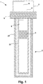
- Fig. 1 discloses a schematic view of a vibronic level gauge 1.
- the vibration system 2 consists of an inner vibrating element 22 and an outer vibrating element 21, wherein the outer vibrating element 21 is tubular and surrounds the inner vibrating element 22 coaxially.
- the inner vibrating element 22 is also substantially tubular.
- a drive / receiving unit 4 excites the vibrating system 2 to mechanical vibrations and receives a signal representing the mechanical vibrations of the vibrating system 2.
- the level gauge 1 can be fastened in such a way in a wall of a container that the vibration system 2 protrudes into the interior of the container.
- a field housing 7 which houses, inter alia, a control / evaluation unit 8, for example in the form of a microcontroller, for controlling the measurement and determination of the fill level, remains outside the container.
- a control / evaluation unit 8 for example in the form of a microcontroller, for controlling the measurement and determination of the fill level.
- the drive / receiving unit 4 is arranged in the field housing 7.
- the drive / receiving unit 4 is designed, for example, as a piezoelectric converter unit.
- Such converter units are well known from the prior art, so that is only roughly discussed here on the operation.
- a plurality of piezoelectric drive elements and piezoelectric receiving elements arranged in a stack which is biased between a fixing means in the field housing 7 and a base of the oscillating system 2 is introduced.
- a disk-shaped piezoelectric element is polarized in such a way and provided with an electrode structure that the element serves both as a drive element and as a receiving element.
- Embodiments are also known in which the inner oscillating element 22 is connected to the outer vibrating element 21 in the end region remote from the process connection 5 and the drive / receiving unit 4 is arranged in this end region facing the process. All embodiments have in common that the control / evaluation unit 8, the piezoelectric transducer unit applied with an electrical excitation signal, which leads to a deformation of the drive elements. The mechanical movements of the oscillating system 2 are converted by the converter unit into an electrical received signal, which evaluates the control / evaluation unit 8 for determining the filling level.
- the oscillating system can be excited to oscillate, for example by means of a magnetoelectric drive, wherein the receiving unit can also be configured magnetoelectrically or piezoelectrically.
- the control / evaluation unit 8 For level measurement, the control / evaluation unit 8 generates the drive signal in such a way that the drive / receiving unit 4 excites the oscillating system 2 to resonant oscillations.
- the outer vibrating member 21 and the inner vibrating member 22 are configured to vibrate at the same resonance frequency.
- the outer oscillating element 21 in this case oscillates in the opposite direction to the inner oscillating element 22. This avoids that forces acting on the process connection 5, which could falsify the measurement.
- the control / evaluation unit 8 evaluates the amplitude of the electrical received signal. If the outer vibrating element 21 is covered with the medium to be detected, the mechanical vibrations are damped, which is accompanied by a reduced amplitude.
- a compensation device 3 is arranged in the inner oscillating element 22, by means of which the mass moment of inertia of the inner oscillating element 22 can be adjusted such that the oscillating system 2 is adjusted again.
- the electronic unit 6 determines the oscillation amplitude of the oscillation system 2 or the inner oscillating element 22 and performs the compensation device 3 in such a way that an amplitude maximum is established. The shift is preferably triggered by a change in the resonant frequency.
- the electronic unit 6 determines the direction of the change of the resonance frequency and controls the direction of the displacement of the compensation device 3 accordingly.
- the resonant frequency of the oscillating system 2 decreases, so that a displacement of the compensating device 3 away from the process connection 5 is required. Corrosion requires a shift in the opposite direction.
- the compensation device 3 represents a movable mass whose displacement in the axial direction due to the coupling of the inner oscillating element 22 and the outer oscillating element 21 causes a change in the resonant frequency and amplitude of the oscillatory system 2.
- Compensation devices in the form of an axially displaceable additional mass are known from the prior art.
- the compensation device 3 is now designed such that it can be displaced by means of the inchworm principle. This offers the advantage that the compensation device 3 reposition itself depending on electrical control signals. A manual move is not required. Furthermore, a motor in the field housing 7, which would be required for an automatic actuation of a displacement device, can be dispensed with.
- the electrical control signals for the compensation device 3 are generated by the electronic unit 6.
- the electronic unit 6 can be configured as part of the control / evaluation unit 8 or as a separate unit.
- the electronic unit 6 is designed as a microcontroller.
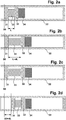
- Fig. 2a shows the resting state of the compensation device 3.
- the compensation device 3 In the idle state, the compensation device 3 is fixed at a certain position S0. In the position S0, the resonance frequencies and the moments of inertia of the inner vibrating element 22 and the outer vibrating element 21 coincide.
- the position S0 of a vibration system calibrated during manufacture is, for example, from the process connection 5 at one quarter of the length of the inner oscillating element 22. From this starting position, the compensating device 3 is displaceable in the axial direction.
- the starting position S0 assumed in the production is designated as rest state, but in each case a state in which the oscillating system is adjusted, ie the compensating device 3 is positioned and frictionally connected to the inner oscillating element 22 such that the resonant frequencies of the outer oscillating element 21 and match inside vibrating element 22.
- the compensation device 3 has a first locking element 31 and a second locking element 32, which are firmly connected to one another via a coupling element 33.
- An additional mass 34 whose position influences the mass moment of inertia and thus also the resonant frequency and oscillation amplitude of the inner oscillating element 22, is fastened to the second arresting element 32. Material and mass of the additional mass 34 are arbitrary depending on the design of the vibration system.
- the system of locking elements 31, 32 and coupling element 33 serves to transport the additional mass 34.
- the additional mass 34 carries the essential portion of the total mass of the compensation device 3.
- no additional mass 34 is present.
- the locking elements 31, 32 and the coupling element 33 form the additional mass to compensate for a modified moment of inertia of the outer vibrating element 21. Furthermore, embodiments are possible which lie between the extreme cases mentioned.
- First locking element 31 and second locking element 32 are disk-shaped.
- the inner diameter of the inner vibrating element 22 coincides with the diameter of the first arresting element 31 and the second arresting element 32, so that these elements 31, 32 have mechanical contact with the inner wall of the inner vibrating element 22.
- the two locking elements 31, 32 are non-positively connected to the inner wall of the inner vibrating element 22.
- the diameter of the coupling element 33 is less than the diameter of the locking elements 31, 32, so that there is no direct mechanical contact with the inner oscillating element 22.
- the thickness, i. the dimension L in the axial direction may be equal to, less than or greater than the thickness of the locking elements 31, 32.
- the thickness of the coupling element 33 is greater than that of the locking elements 31, 32.
- the thickness of the locking elements 31, 32 and the coupling element 33 is between 1 and 10 millimeters.
- the two locking elements 31, 32, as well as the coupling element 33 consist of a piezoelectric material. Piezoelectric elements change their volume upon application of an electrical voltage, with expansion or shrinkage taking place primarily in the direction of polarization. While the two locking elements 31, 32 are polarized in the radial direction, the coupling element 33 has a polarization in the axial direction.
- the two circular side surfaces of the disc-shaped locking elements 31, 32 are each provided with an electrode, for example in the form of a coating, so that an electrical voltage to the locking elements 31, 32 can be applied. Due to the polarization in the radial direction, a locking element 31, 32 undergoes a change in length in the radial direction when subjected to a voltage. For example, the first locking element 31 and the second locking element 32 are acted upon in the idle state with a voltage, whereby the two locking elements 31, 32 are fixed in the tubular inner oscillating element 22.
- the position of the compensation device 3 is variable.
- the tracking of the position is carried out iteratively in each case by a distance dL, until the oscillation amplitude of the inner oscillating element 22 assumes a maximum value and the energy balance is restored.
- the oscillation amplitude of the entire oscillation system 2 is maximum.
- the displacement distance dL is relatively low and is usually in the range of a few micrometers.
- a correspondingly high clock rate for the repeated displacement by the distance dL is required.
- the clock rate is dynamically changeable.
- the electronic unit 6 determines the required shift and selects the clock rate according to the route length.
- control / evaluation unit 8 and / or the electronic unit 6 determines an occurring change in the resonance frequency quantitatively and determines the displacement required for compensation or the required position of the compensation device 3.
- the difference between the current resonance frequency and the previously in balanced state assumed resonant frequency determined.
- the position of the compensation device 3 or the distance by which the compensation device 3 is to move can be determined therefrom.
- an acceleration sensor measures forces which occur in the case of an uncompensated oscillatory system, and the electronics unit 6 controls the displacement of the compensation device 3 in such a way that the forces occurring are minimal.
- a first step for shifting the compensation device 3 is in Fig. 2b shown.
- the electronic unit 6 reduces the voltage applied to the second locking element 32, preferably to zero. This reduces the diameter of the second locking element 32 so that there is no contact with the inner wall.
- the electronics unit 6 acts on the coupling element 33 with a voltage. As a result, the coupling element 33 undergoes a change in length in the axial direction by an amount dL. Since the first locking element 31 is fixed at the position S0, the second locking element 32 and the additional mass undergo a displacement in the axial direction by the distance dL due to the change in length by dL.
- the electronics unit 6 releases the connection of the first locking element 31 with the inner oscillating element 22 by interrupting or at least reducing the application of the voltage. Furthermore, the electronic unit 6 terminates the application of the previously applied voltage to the coupling element 33. The coupling element 33 thereby assumes its original length L again. By fixing the second locking element 32 on the inner wall, the coupling element 33 retracts the first locking element 31, so that now also the first locking element 31 advances to the position S0 + dL.
- the compensation device 3 is again in the Fig. 2a shown idle state, but at the point S0 + dL.
- the cycle described is preferably followed immediately by the next of n cycles until the final state is reached at the position S0 + ndL.
Landscapes
- Physics & Mathematics (AREA)
- Acoustics & Sound (AREA)
- Electromagnetism (AREA)
- Thermal Sciences (AREA)
- Fluid Mechanics (AREA)
- General Physics & Mathematics (AREA)
- Measurement Of Levels Of Liquids Or Fluent Solid Materials (AREA)
- Measurement Of Mechanical Vibrations Or Ultrasonic Waves (AREA)
Claims (10)
- Transmetteur de niveau (1) avec un système de vibration (2) pouvant être excité en vibrations mécaniques, lequel système comporte au moins un élément de vibration tubulaire extérieur (21) et un élément de vibration intérieur (22), l'élément de vibration extérieur (21) entourant au moins partiellement de manière coaxiale l'élément de vibration intérieur (22),
caractérisé
en ce qu'est disposé, dans un espace intérieur de l'élément de vibration intérieur (22), un dispositif de compensation (3) déplaçable en direction axiale, lequel dispositif présente au moins un élément d'arrêt (31), un deuxième élément d'arrêt (32) et un élément de couplage (33), les éléments d'arrêt (31, 32) et l'élément de couplage (33) étant constitués d'un matériau piézoélectrique, l'élément de couplage (33) reliant entre eux le premier élément d'arrêt (31) et le deuxième élément d'arrêt (32), et le premier élément d'arrêt (31) et le deuxième élément d'arrêt (32) étant chacun reliés, dans une position de repos, par une liaison de force avec une paroi de l'espace intérieur,
et
en ce que le transmetteur de niveau (1) comporte une unité électronique (6), laquelle est conçue de telle sorte à positionner le dispositif de compensation (3) sur une position prédéfinissable au moyen de signaux électriques. - Transmetteur de niveau selon la revendication 1,
caractérisé
en ce qu'est fixée, sur le premier élément d'arrêt (31) et/ou sur le deuxième élément d'arrêt (32), une masse supplémentaire (34). - Transmetteur de niveau selon la revendication 1 ou 2,
caractérisé
en ce que l'élément de vibration intérieur (22) est au moins partiellement tubulaire. - Transmetteur de niveau selon au moins l'une des revendications précédentes,
caractérisé
en ce que le dispositif de compensation (3) est conçu de telle sorte à se déplacer en direction axiale selon le principe de la chenille arpenteuse. - Transmetteur de niveau selon au moins l'une des revendications précédentes,
caractérisé
en ce que les éléments d'arrêt (31, 32) sont polarisés en direction radiale et l'élément de couplage (33) en direction axiale. - Transmetteur de niveau selon au moins l'une des revendications précédentes,
caractérisé
en ce que l'élément de couplage (33) est conçu de telle sorte que l'élément de couplage (33) subit, en cas d'alimentation avec une tension électrique, un allongement longitudinal en direction axiale. - Transmetteur de niveau selon au moins l'une des revendications précédentes,
caractérisé
en ce que l'unité électronique (6) alimente, à l'état de repos, le premier élément d'arrêt (31) et le deuxième élément d'arrêt (32) avec une tension électrique
et
en ce que l'unité électronique (6) réduit, en vue de la suppression de la liaison par force entre la paroi et le premier élément d'arrêt (31) ou le deuxième élément d'arrêt (32), la tension électrique avec laquelle le premier élément d'arrêt (31) ou le deuxième élément d'arrêt (32) sont alimentés à l'état de repos. - Transmetteur de niveau selon au moins l'une des revendications précédentes,
caractérisé
en ce qu'est prévue une unité d'entraînement / de réception (4), laquelle fait entrer l'élément de vibration extérieur (21) et l'élément de vibration intérieur (22) en vibrations mécaniques de sens contraire, à la fréquence de résonance du système de vibration (2). - Transmetteur de niveau selon au moins l'une des revendications précédentes,
caractérisé
en ce que l'unité électronique (6) est conçue de telle sorte à déplacer le dispositif de compensation (3) en cas de modification de la fréquence des vibrations du système de vibration (2). - Transmetteur de niveau selon la revendication précédente,
caractérisé
en ce que l'unité électronique (6) est conçue de telle sorte à positionner le dispositif de compensation (3) afin que l'amplitude des vibrations de l'élément de vibration intérieur (22) soit maximale.
Applications Claiming Priority (2)
| Application Number | Priority Date | Filing Date | Title |
|---|---|---|---|
| DE102012103165A DE102012103165A1 (de) | 2012-04-12 | 2012-04-12 | Füllstandsmessgerät |
| PCT/EP2013/055616 WO2013152926A1 (fr) | 2012-04-12 | 2013-03-19 | Appareil de mesure du niveau de remplissage |
Publications (2)
| Publication Number | Publication Date |
|---|---|
| EP2836802A1 EP2836802A1 (fr) | 2015-02-18 |
| EP2836802B1 true EP2836802B1 (fr) | 2019-09-25 |
Family
ID=47913415
Family Applications (1)
| Application Number | Title | Priority Date | Filing Date |
|---|---|---|---|
| EP13711024.3A Active EP2836802B1 (fr) | 2012-04-12 | 2013-03-19 | Appareil de mesure du niveau de remplissage |
Country Status (5)
| Country | Link |
|---|---|
| US (1) | US9829367B2 (fr) |
| EP (1) | EP2836802B1 (fr) |
| CN (1) | CN104204736B (fr) |
| DE (1) | DE102012103165A1 (fr) |
| WO (1) | WO2013152926A1 (fr) |
Families Citing this family (10)
| Publication number | Priority date | Publication date | Assignee | Title |
|---|---|---|---|---|
| EP2803954B1 (fr) * | 2013-05-15 | 2019-01-02 | VEGA Grieshaber KG | Dispositif de mesure de niveau de remplissage |
| EP2811269A1 (fr) * | 2013-06-06 | 2014-12-10 | VEGA Grieshaber KG | Appareil de mesure de niveaux multiples |
| CN104634419B (zh) * | 2015-02-03 | 2017-12-26 | 深圳计为自动化技术有限公司 | 振动式物料开关的质量块、振动装置及谐振频率调试方法 |
| DE102015103071B3 (de) * | 2015-03-03 | 2015-11-12 | Endress + Hauser Gmbh + Co. Kg | Vibronischer Sensor mit einem Stellelement |
| DE102015122648B4 (de) * | 2015-12-22 | 2025-07-31 | Vega Grieshaber Kg | Füllstandmessvorrichtung |
| CN105712059B (zh) * | 2016-04-13 | 2019-05-03 | 龙岩烟草工业有限责任公司 | 料位传感器位置调节装置及卷烟制丝喂料机 |
| WO2019078842A1 (fr) * | 2017-10-18 | 2019-04-25 | Hewlett-Packard Development Company, L.P. | Capteurs de niveau de fluide |
| DE102019112866A1 (de) * | 2019-05-16 | 2020-11-19 | Endress+Hauser SE+Co. KG | Zustandsüberwachung eines vibronischen Sensors |
| DE102019118156A1 (de) * | 2019-07-04 | 2021-01-07 | Endress+Hauser Conducta Gmbh+Co. Kg | Wechselarmatur, System und Verfahren zur Erkennung einer Bewegung in einer solchen |
| DE102024110947A1 (de) | 2024-04-18 | 2025-10-23 | Endress+Hauser SE+Co. KG | Vibrationssensor und Verfahren zum Abgleichen eines Vibrationssensors |
Family Cites Families (10)
| Publication number | Priority date | Publication date | Assignee | Title |
|---|---|---|---|---|
| JPS60144619A (ja) * | 1984-01-06 | 1985-07-31 | Nouken Kogyo Kk | 振動式レベル検出器 |
| DE3625779A1 (de) | 1986-07-30 | 1988-02-04 | Vega Grieshaber Gmbh & Co | Vorrichtung zum feststellen eines bestimmten fuellstandes in einem behaelter |
| DE3808481C2 (de) * | 1988-03-14 | 1997-11-27 | Endress Hauser Gmbh Co | Vorrichtung zur Feststellung eines bestimmten Füllstandes in einem Behälter |
| DE19651362C1 (de) | 1996-12-10 | 1998-06-10 | Endress Hauser Gmbh Co | Vorrichtung zur Überwachung eines vorbestimmten Füllstands in einem Behälter |
| DE10318705A1 (de) * | 2003-04-24 | 2004-11-18 | Endress + Hauser Gmbh + Co. Kg | Vorrichtung zur Bestimmung und/oder Überwachung mindestens einer physikalischen oder chemischen Prozessgröße eines Mediums |
| CN1611340A (zh) | 2003-10-29 | 2005-05-04 | 昆山渝隆精密模具制品有限公司 | 生产手机键盘的注塑成型方法 |
| DE102004009495B4 (de) * | 2004-02-27 | 2009-09-24 | Vega Grieshaber Kg | Abgleichkörper für eine Füllstandsmessvorrichtung |
| DE102004011377A1 (de) | 2004-03-05 | 2005-09-15 | Endress + Hauser Gmbh + Co. Kg | Vorrichtung zur Bestimmung und/oder Überwachung einer Prozessgrösse |
| WO2011079221A2 (fr) * | 2009-12-23 | 2011-06-30 | Baker Hughes Incorporated | Outils de fond de trou avec entraînements électromécaniques et électrohydrauliques |
| WO2012113776A1 (fr) * | 2011-02-23 | 2012-08-30 | Gaslock Gmbh | Dispositif de mesure du niveau de liquides |
-
2012
- 2012-04-12 DE DE102012103165A patent/DE102012103165A1/de not_active Withdrawn
-
2013
- 2013-03-19 CN CN201380019267.9A patent/CN104204736B/zh active Active
- 2013-03-19 WO PCT/EP2013/055616 patent/WO2013152926A1/fr not_active Ceased
- 2013-03-19 US US14/391,187 patent/US9829367B2/en not_active Expired - Fee Related
- 2013-03-19 EP EP13711024.3A patent/EP2836802B1/fr active Active
Non-Patent Citations (1)
| Title |
|---|
| None * |
Also Published As
| Publication number | Publication date |
|---|---|
| CN104204736B (zh) | 2017-07-21 |
| US20150068300A1 (en) | 2015-03-12 |
| WO2013152926A1 (fr) | 2013-10-17 |
| CN104204736A (zh) | 2014-12-10 |
| US9829367B2 (en) | 2017-11-28 |
| EP2836802A1 (fr) | 2015-02-18 |
| DE102012103165A1 (de) | 2013-10-17 |
Similar Documents
| Publication | Publication Date | Title |
|---|---|---|
| EP2836802B1 (fr) | Appareil de mesure du niveau de remplissage | |
| EP0848237B1 (fr) | Dispositif de surveillance d'un niveau prédéterminé de remplissage dans un réservoir | |
| DE4118793C2 (de) | Vorrichtung zur Feststellung und/oder Überwachung eines vorbestimmten Füllstandes in einem Behälter | |
| DE3336991C2 (fr) | ||
| DE3878473T2 (de) | Wandler fuer fluessigkeiten. | |
| EP2612114B1 (fr) | Système de mesure comprenant un capteur de mesure de type vibratoire | |
| EP3472578B1 (fr) | Capteur vibronique et procédé de fonctionnement d'un capteur vibronique | |
| EP1529202B1 (fr) | Dispositif pour surveiller un etat de remplissage predefini d'un milieu a mesurer dans un recipient | |
| EP2588842B1 (fr) | Dispositif pour déterminer et/ou surveiller une grandeur de processus d'un milieu | |
| EP2350577B1 (fr) | Dispositif à aimant et capteur de mesure de type à vibrations le comprenant | |
| DE102006033819A1 (de) | Vorrichtung zur Bestimmung und/oder Überwachung einer Prozessgröße eines Mediums | |
| DE1773815B2 (de) | Vorrichtung zur Feststellung des Erreichens eines vorbestimmten Füllstands in einem Behälter | |
| DE3923409A1 (de) | Nach dem coriolis-prinzip arbeitendes massendurchfluss-messgeraet | |
| DE102011090015B4 (de) | Vorrichtung zur Bestimmung und/oder Überwachung mindestens einer Prozessgröße | |
| DE3723933A1 (de) | Verfahren zum erfassen einer kleinflaechigen, nahezu punktfoermigen und weitgehend kraeftefreien beruehrung zwischen einer sonde und einem festen gegenstand, sowie beruehrungsdetektor | |
| DE3348119C2 (en) | Device for ascertaining and/or monitoring a predetermined filling level in a container | |
| WO1983001307A1 (fr) | Mesure du niveau de remplissage | |
| DE3140938C2 (fr) | ||
| EP1026492A2 (fr) | Dispositif sans fil de mesure de couple et capteur pour ce dispositif | |
| EP3056877B1 (fr) | Agencement de mesure de vibration | |
| EP1996905A1 (fr) | Dispositif de détermination et/ou de surveillance d'un paramètre de traitement | |
| WO2014146980A1 (fr) | Dispositif de détermination et/ou de surveillance d'une grandeur de processus d'un milieu | |
| DE102022116111A1 (de) | Vibronisches Meßsystem | |
| EP1695046B1 (fr) | Procede et dispositif pour produire un dispositif de mesure pour determiner et/ou surveiller une variable de processus et dispositif de mesure correspondant | |
| DE3733345C2 (fr) |
Legal Events
| Date | Code | Title | Description |
|---|---|---|---|
| PUAI | Public reference made under article 153(3) epc to a published international application that has entered the european phase |
Free format text: ORIGINAL CODE: 0009012 |
|
| 17P | Request for examination filed |
Effective date: 20140827 |
|
| AK | Designated contracting states |
Kind code of ref document: A1 Designated state(s): AL AT BE BG CH CY CZ DE DK EE ES FI FR GB GR HR HU IE IS IT LI LT LU LV MC MK MT NL NO PL PT RO RS SE SI SK SM TR |
|
| AX | Request for extension of the european patent |
Extension state: BA ME |
|
| DAX | Request for extension of the european patent (deleted) | ||
| RAP1 | Party data changed (applicant data changed or rights of an application transferred) |
Owner name: ENDRESS+HAUSER SE+CO. KG |
|
| GRAP | Despatch of communication of intention to grant a patent |
Free format text: ORIGINAL CODE: EPIDOSNIGR1 |
|
| STAA | Information on the status of an ep patent application or granted ep patent |
Free format text: STATUS: GRANT OF PATENT IS INTENDED |
|
| INTG | Intention to grant announced |
Effective date: 20190523 |
|
| GRAS | Grant fee paid |
Free format text: ORIGINAL CODE: EPIDOSNIGR3 |
|
| GRAA | (expected) grant |
Free format text: ORIGINAL CODE: 0009210 |
|
| STAA | Information on the status of an ep patent application or granted ep patent |
Free format text: STATUS: THE PATENT HAS BEEN GRANTED |
|
| AK | Designated contracting states |
Kind code of ref document: B1 Designated state(s): AL AT BE BG CH CY CZ DE DK EE ES FI FR GB GR HR HU IE IS IT LI LT LU LV MC MK MT NL NO PL PT RO RS SE SI SK SM TR |
|
| REG | Reference to a national code |
Ref country code: GB Ref legal event code: FG4D Free format text: NOT ENGLISH |
|
| REG | Reference to a national code |
Ref country code: CH Ref legal event code: EP |
|
| REG | Reference to a national code |
Ref country code: AT Ref legal event code: REF Ref document number: 1184259 Country of ref document: AT Kind code of ref document: T Effective date: 20191015 |
|
| REG | Reference to a national code |
Ref country code: IE Ref legal event code: FG4D Free format text: LANGUAGE OF EP DOCUMENT: GERMAN |
|
| REG | Reference to a national code |
Ref country code: DE Ref legal event code: R096 Ref document number: 502013013648 Country of ref document: DE |
|
| REG | Reference to a national code |
Ref country code: NL Ref legal event code: MP Effective date: 20190925 |
|
| PG25 | Lapsed in a contracting state [announced via postgrant information from national office to epo] |
Ref country code: FI Free format text: LAPSE BECAUSE OF FAILURE TO SUBMIT A TRANSLATION OF THE DESCRIPTION OR TO PAY THE FEE WITHIN THE PRESCRIBED TIME-LIMIT Effective date: 20190925 Ref country code: NO Free format text: LAPSE BECAUSE OF FAILURE TO SUBMIT A TRANSLATION OF THE DESCRIPTION OR TO PAY THE FEE WITHIN THE PRESCRIBED TIME-LIMIT Effective date: 20191225 Ref country code: BG Free format text: LAPSE BECAUSE OF FAILURE TO SUBMIT A TRANSLATION OF THE DESCRIPTION OR TO PAY THE FEE WITHIN THE PRESCRIBED TIME-LIMIT Effective date: 20191225 Ref country code: SE Free format text: LAPSE BECAUSE OF FAILURE TO SUBMIT A TRANSLATION OF THE DESCRIPTION OR TO PAY THE FEE WITHIN THE PRESCRIBED TIME-LIMIT Effective date: 20190925 Ref country code: LT Free format text: LAPSE BECAUSE OF FAILURE TO SUBMIT A TRANSLATION OF THE DESCRIPTION OR TO PAY THE FEE WITHIN THE PRESCRIBED TIME-LIMIT Effective date: 20190925 Ref country code: HR Free format text: LAPSE BECAUSE OF FAILURE TO SUBMIT A TRANSLATION OF THE DESCRIPTION OR TO PAY THE FEE WITHIN THE PRESCRIBED TIME-LIMIT Effective date: 20190925 |
|
| REG | Reference to a national code |
Ref country code: LT Ref legal event code: MG4D |
|
| PG25 | Lapsed in a contracting state [announced via postgrant information from national office to epo] |
Ref country code: RS Free format text: LAPSE BECAUSE OF FAILURE TO SUBMIT A TRANSLATION OF THE DESCRIPTION OR TO PAY THE FEE WITHIN THE PRESCRIBED TIME-LIMIT Effective date: 20190925 Ref country code: LV Free format text: LAPSE BECAUSE OF FAILURE TO SUBMIT A TRANSLATION OF THE DESCRIPTION OR TO PAY THE FEE WITHIN THE PRESCRIBED TIME-LIMIT Effective date: 20190925 Ref country code: GR Free format text: LAPSE BECAUSE OF FAILURE TO SUBMIT A TRANSLATION OF THE DESCRIPTION OR TO PAY THE FEE WITHIN THE PRESCRIBED TIME-LIMIT Effective date: 20191226 |
|
| PG25 | Lapsed in a contracting state [announced via postgrant information from national office to epo] |
Ref country code: PL Free format text: LAPSE BECAUSE OF FAILURE TO SUBMIT A TRANSLATION OF THE DESCRIPTION OR TO PAY THE FEE WITHIN THE PRESCRIBED TIME-LIMIT Effective date: 20190925 Ref country code: AL Free format text: LAPSE BECAUSE OF FAILURE TO SUBMIT A TRANSLATION OF THE DESCRIPTION OR TO PAY THE FEE WITHIN THE PRESCRIBED TIME-LIMIT Effective date: 20190925 Ref country code: PT Free format text: LAPSE BECAUSE OF FAILURE TO SUBMIT A TRANSLATION OF THE DESCRIPTION OR TO PAY THE FEE WITHIN THE PRESCRIBED TIME-LIMIT Effective date: 20200127 Ref country code: ES Free format text: LAPSE BECAUSE OF FAILURE TO SUBMIT A TRANSLATION OF THE DESCRIPTION OR TO PAY THE FEE WITHIN THE PRESCRIBED TIME-LIMIT Effective date: 20190925 Ref country code: NL Free format text: LAPSE BECAUSE OF FAILURE TO SUBMIT A TRANSLATION OF THE DESCRIPTION OR TO PAY THE FEE WITHIN THE PRESCRIBED TIME-LIMIT Effective date: 20190925 Ref country code: RO Free format text: LAPSE BECAUSE OF FAILURE TO SUBMIT A TRANSLATION OF THE DESCRIPTION OR TO PAY THE FEE WITHIN THE PRESCRIBED TIME-LIMIT Effective date: 20190925 Ref country code: IT Free format text: LAPSE BECAUSE OF FAILURE TO SUBMIT A TRANSLATION OF THE DESCRIPTION OR TO PAY THE FEE WITHIN THE PRESCRIBED TIME-LIMIT Effective date: 20190925 Ref country code: EE Free format text: LAPSE BECAUSE OF FAILURE TO SUBMIT A TRANSLATION OF THE DESCRIPTION OR TO PAY THE FEE WITHIN THE PRESCRIBED TIME-LIMIT Effective date: 20190925 |
|
| PG25 | Lapsed in a contracting state [announced via postgrant information from national office to epo] |
Ref country code: SK Free format text: LAPSE BECAUSE OF FAILURE TO SUBMIT A TRANSLATION OF THE DESCRIPTION OR TO PAY THE FEE WITHIN THE PRESCRIBED TIME-LIMIT Effective date: 20190925 Ref country code: SM Free format text: LAPSE BECAUSE OF FAILURE TO SUBMIT A TRANSLATION OF THE DESCRIPTION OR TO PAY THE FEE WITHIN THE PRESCRIBED TIME-LIMIT Effective date: 20190925 Ref country code: CZ Free format text: LAPSE BECAUSE OF FAILURE TO SUBMIT A TRANSLATION OF THE DESCRIPTION OR TO PAY THE FEE WITHIN THE PRESCRIBED TIME-LIMIT Effective date: 20190925 Ref country code: IS Free format text: LAPSE BECAUSE OF FAILURE TO SUBMIT A TRANSLATION OF THE DESCRIPTION OR TO PAY THE FEE WITHIN THE PRESCRIBED TIME-LIMIT Effective date: 20200224 |
|
| REG | Reference to a national code |
Ref country code: DE Ref legal event code: R097 Ref document number: 502013013648 Country of ref document: DE |
|
| PG2D | Information on lapse in contracting state deleted |
Ref country code: IS |
|
| PG25 | Lapsed in a contracting state [announced via postgrant information from national office to epo] |
Ref country code: DK Free format text: LAPSE BECAUSE OF FAILURE TO SUBMIT A TRANSLATION OF THE DESCRIPTION OR TO PAY THE FEE WITHIN THE PRESCRIBED TIME-LIMIT Effective date: 20190925 Ref country code: IS Free format text: LAPSE BECAUSE OF FAILURE TO SUBMIT A TRANSLATION OF THE DESCRIPTION OR TO PAY THE FEE WITHIN THE PRESCRIBED TIME-LIMIT Effective date: 20200126 |
|
| PLBE | No opposition filed within time limit |
Free format text: ORIGINAL CODE: 0009261 |
|
| STAA | Information on the status of an ep patent application or granted ep patent |
Free format text: STATUS: NO OPPOSITION FILED WITHIN TIME LIMIT |
|
| 26N | No opposition filed |
Effective date: 20200626 |
|
| PG25 | Lapsed in a contracting state [announced via postgrant information from national office to epo] |
Ref country code: MC Free format text: LAPSE BECAUSE OF FAILURE TO SUBMIT A TRANSLATION OF THE DESCRIPTION OR TO PAY THE FEE WITHIN THE PRESCRIBED TIME-LIMIT Effective date: 20190925 |
|
| REG | Reference to a national code |
Ref country code: CH Ref legal event code: PL |
|
| PG25 | Lapsed in a contracting state [announced via postgrant information from national office to epo] |
Ref country code: SI Free format text: LAPSE BECAUSE OF FAILURE TO SUBMIT A TRANSLATION OF THE DESCRIPTION OR TO PAY THE FEE WITHIN THE PRESCRIBED TIME-LIMIT Effective date: 20190925 |
|
| REG | Reference to a national code |
Ref country code: BE Ref legal event code: MM Effective date: 20200331 |
|
| PG25 | Lapsed in a contracting state [announced via postgrant information from national office to epo] |
Ref country code: LU Free format text: LAPSE BECAUSE OF NON-PAYMENT OF DUE FEES Effective date: 20200319 |
|
| PG25 | Lapsed in a contracting state [announced via postgrant information from national office to epo] |
Ref country code: LI Free format text: LAPSE BECAUSE OF NON-PAYMENT OF DUE FEES Effective date: 20200331 Ref country code: CH Free format text: LAPSE BECAUSE OF NON-PAYMENT OF DUE FEES Effective date: 20200331 Ref country code: FR Free format text: LAPSE BECAUSE OF NON-PAYMENT OF DUE FEES Effective date: 20200331 Ref country code: IE Free format text: LAPSE BECAUSE OF NON-PAYMENT OF DUE FEES Effective date: 20200319 |
|
| PG25 | Lapsed in a contracting state [announced via postgrant information from national office to epo] |
Ref country code: BE Free format text: LAPSE BECAUSE OF NON-PAYMENT OF DUE FEES Effective date: 20200331 |
|
| GBPC | Gb: european patent ceased through non-payment of renewal fee |
Effective date: 20200319 |
|
| PG25 | Lapsed in a contracting state [announced via postgrant information from national office to epo] |
Ref country code: GB Free format text: LAPSE BECAUSE OF NON-PAYMENT OF DUE FEES Effective date: 20200319 |
|
| REG | Reference to a national code |
Ref country code: AT Ref legal event code: MM01 Ref document number: 1184259 Country of ref document: AT Kind code of ref document: T Effective date: 20200319 |
|
| PG25 | Lapsed in a contracting state [announced via postgrant information from national office to epo] |
Ref country code: AT Free format text: LAPSE BECAUSE OF NON-PAYMENT OF DUE FEES Effective date: 20200319 |
|
| PG25 | Lapsed in a contracting state [announced via postgrant information from national office to epo] |
Ref country code: TR Free format text: LAPSE BECAUSE OF FAILURE TO SUBMIT A TRANSLATION OF THE DESCRIPTION OR TO PAY THE FEE WITHIN THE PRESCRIBED TIME-LIMIT Effective date: 20190925 Ref country code: MT Free format text: LAPSE BECAUSE OF FAILURE TO SUBMIT A TRANSLATION OF THE DESCRIPTION OR TO PAY THE FEE WITHIN THE PRESCRIBED TIME-LIMIT Effective date: 20190925 Ref country code: CY Free format text: LAPSE BECAUSE OF FAILURE TO SUBMIT A TRANSLATION OF THE DESCRIPTION OR TO PAY THE FEE WITHIN THE PRESCRIBED TIME-LIMIT Effective date: 20190925 |
|
| PG25 | Lapsed in a contracting state [announced via postgrant information from national office to epo] |
Ref country code: MK Free format text: LAPSE BECAUSE OF FAILURE TO SUBMIT A TRANSLATION OF THE DESCRIPTION OR TO PAY THE FEE WITHIN THE PRESCRIBED TIME-LIMIT Effective date: 20190925 |
|
| P01 | Opt-out of the competence of the unified patent court (upc) registered |
Effective date: 20230601 |
|
| PGFP | Annual fee paid to national office [announced via postgrant information from national office to epo] |
Ref country code: DE Payment date: 20260319 Year of fee payment: 14 |