US9829367B2 - Fill-level measuring device - Google Patents
Fill-level measuring device Download PDFInfo
- Publication number
- US9829367B2 US9829367B2 US14/391,187 US201314391187A US9829367B2 US 9829367 B2 US9829367 B2 US 9829367B2 US 201314391187 A US201314391187 A US 201314391187A US 9829367 B2 US9829367 B2 US 9829367B2
- Authority
- US
- United States
- Prior art keywords
- oscillatory
- locking element
- fill
- measuring device
- level measuring
- Prior art date
- Legal status (The legal status is an assumption and is not a legal conclusion. Google has not performed a legal analysis and makes no representation as to the accuracy of the status listed.)
- Expired - Fee Related, expires
Links
Images


Classifications
-
- G—PHYSICS
- G01—MEASURING; TESTING
- G01F—MEASURING VOLUME, VOLUME FLOW, MASS FLOW OR LIQUID LEVEL; METERING BY VOLUME
- G01F23/00—Indicating or measuring liquid level or level of fluent solid material, e.g. indicating in terms of volume or indicating by means of an alarm
- G01F23/22—Indicating or measuring liquid level or level of fluent solid material, e.g. indicating in terms of volume or indicating by means of an alarm by measuring physical variables, other than linear dimensions, pressure or weight, dependent on the level to be measured, e.g. by difference of heat transfer of steam or water
- G01F23/28—Indicating or measuring liquid level or level of fluent solid material, e.g. indicating in terms of volume or indicating by means of an alarm by measuring physical variables, other than linear dimensions, pressure or weight, dependent on the level to be measured, e.g. by difference of heat transfer of steam or water by measuring the variations of parameters of electromagnetic or acoustic waves applied directly to the liquid or fluent solid material
- G01F23/296—Acoustic waves
- G01F23/2966—Acoustic waves making use of acoustical resonance or standing waves
- G01F23/2967—Acoustic waves making use of acoustical resonance or standing waves for discrete levels
Definitions
- the present invention relates to a fill-level measuring device having an oscillatory system, which has at least one external, tubular, oscillatory element and an inner oscillatory element, wherein the outer oscillatory element at least sectionally coaxially surrounds the inner oscillatory element.
- Such fill level measuring devices are also known as single rod measuring devices.
- the fill-level measuring device serves for registering the fill level of a medium, especially of a bulk good, in a container.
- the fill-level measuring device is used as a limit level switch for monitoring a predetermined maximum or minimum fill level.
- German patent DE 19651362 C1 is a measuring device for fill-level monitoring having an oscillatory system, which is composed of two rods.
- an inner oscillatory rod is surrounded coaxially by an outer tubular oscillatory rod.
- Each of the oscillatory rods is secured via an elastic holding part to a shared carrier and are excited to execute opposite transverse oscillations with the eigenresonance frequency of the oscillatory system.
- the measuring device is mounted on a container in such a manner that the outer oscillatory rod contacts the fill substance as soon as such reaches the fill level to be monitored. Serving as measured variable for fill level detection is the oscillation amplitude.
- the inner oscillatory rod includes a compensation mass, which is shiftably arranged, so that the resonant frequency of the inner oscillatory structure is adaptable to that of the outer oscillatory structure.
- the compensation mass is secured, for example, on an axially extending rod, which has a screw thread.
- a motor rotates the rod in such a manner that the compensation mass moves in the axial direction.
- EP 2273239 A1 is a fill level measuring apparatus, which likewise has two tubular oscillatory bodies arranged in one another.
- the outer oscillatory body is secured to a securement system via an elastic section.
- a tuning body Arranged in the interior of the inner oscillatory body is a tuning body.
- the tuning body is sectionally elastically embodied and placed under compression in the inner oscillatory body.
- the tuning body includes a section with an external thread, which is matched to an internal thread in the inner wall of the inner oscillatory body.
- a frontal slot is provided, in which a displacement instrument, for example, a screw driver, can engage. The adjusting occurs manually or via a motor driven control.
- a manual adjusting of the tuning body via the rod-shaped displacement instrument is uncomfortable.
- a motor control in contrast, is complicated to put into practice.
- the described oscillatory system is relatively complicated to manufacture, because of the screw thread.
- An object of the invention is to provide a fill-level measuring device having an easily displaceable tuning body.
- a compensation apparatus shiftable in the axial direction and having at least a first locking element, a second locking element and a coupling element is arranged, wherein the locking elements and the coupling element are composed of piezoelectric material, wherein the coupling element, the first locking element and the second locking element are connected with one another, and wherein the first locking element and the second locking element in a resting state are connected by force interlocking, e.g. friction interlocking, with a wall of the inner space, and that the fill-level measuring device has an electronics unit, which is embodied to position the compensation apparatus at a predeterminable position by means of electrical signals.
- an energy non-equilibrium such as can arise, for example, due to accretion formation on the outer oscillatory element or due to corrosion, is compensatable.
- an added mass is secured to the first locking element and/or the second locking element.
- the inner oscillatory element is at least sectionally tubular.
- the compensation apparatus is embodied to move itself in the axial direction according to the inchworm principle.
- An embodiment includes that the locking elements are polarized in the radial direction and the coupling element in the axial direction.
- the coupling element is embodied in such a manner that the coupling element in the case of being supplied with an electrical voltage experiences a longitudinal extension in the axial direction.
- An embodiment provides that the electronics unit supplies the first locking element and the second locking element in the resting state with an electrical voltage and that the electronics unit for releasing the force interlocked connection between the wall and the first locking element or the second locking element reduces the electrical voltage, which the first locking element or the second locking element is supplied in the resting state.
- a driving/receiving unit which excites the outer oscillatory element and the inner oscillatory element to execute opposite mechanical oscillations with the resonant frequency.
- the electronics unit is embodied to shift the compensation apparatus upon a change of the frequency of the oscillations of the oscillatory system.
- the electronics unit is embodied to position the compensation apparatus in such a manner that the amplitude of the oscillations of the inner oscillatory element is maximum.
- the fill-level measuring device of the invention has an automatically positionable tuning body in the form of the compensation apparatus. If accretion forms on the outer oscillatory element or corrosion occurs, there arises a non-equilibrium of the mass moment of inertia of the inner oscillatory element and of the outer oscillatory element. This is recognizable by a change of the oscillation frequency of the oscillatory system, as well as a lessened oscillation amplitude.
- the compensation apparatus is axially shiftable such that the mass moment of inertia of the inner oscillatory element is adjustable and thereby the oscillatory equilibrium is reestablished.
- the compensation apparatus positions itself at the position in the inner oscillatory element required for this. To this end, only a corresponding control signal is required, which the electronics unit produces.
- the electronics unit calculates either the required position of the compensation apparatus and produces the control signal correspondingly, or the electronics unit monitors the oscillatory equilibrium and produces the control signal in such a manner that the resting state is maintained, in case the oscillatory system is tuned, and that the compensation apparatus shifts in the axial direction, if this is not the case. Since the movement of the compensation apparatus occurs according to the inchworm principle, the shifting occurs in steps of constant length. This step-wise movement is repeated until the position is achieved, at which the mass moment of inertia of inner and outer oscillatory elements at least essentially agree.
- FIG. 1 is a fill-level measuring device having an oscillatory system with an inner and an outer oscillatory element
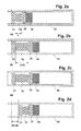
- FIG. 2 a shows the compensation apparatus in the inner oscillatory element in the resting state
- FIGS. 2 b -2 d shows stages of the compensation apparatus in the inner oscillatory element during the shifting of the compensation apparatus.
- FIG. 1 is a schematic view of a vibronic fill-level measuring device 1 .
- the oscillatory system 2 is composed of an inner oscillatory element 22 and an outer oscillatory element 21 , wherein the outer oscillatory element 21 is tubular and coaxially surrounds the inner oscillatory element 22 .
- the inner oscillatory element 22 is likewise essentially tubular.
- the outer oscillatory element 21 and the inner oscillatory element 22 are mechanically coupled with one another.
- a driving/receiving unit 4 excites the oscillatory system 2 to execute mechanical oscillations and receives a signal representing the mechanical oscillations of the oscillatory system 2 .
- the fill-level measuring device 1 is securable in a wall of a container in such a manner that the oscillatory system 2 protrudes inwardly into the interior of the container.
- a field housing 7 which, among other things, accommodates a control/evaluation unit 8 , for example, in the form of a microcontroller, for controlling the measuring and determining the fill level, remains outside of the container.
- the driving/receiving unit 4 is arranged in the field housing 7 .
- Driving/receiving unit 4 is embodied, for example, as a piezoelectric transducer unit.
- Such transducer units are sufficiently known from the state of the art, so that here their operation is explored only briefly.
- a plurality of piezoelectric drive elements and piezoelectric receiving elements are arranged in a stack, which is placed under prestress between a securement means in the field housing 7 and a base of the oscillatory system 2 .
- a disc shaped piezoelectric element is polarized in such a manner and provided with an electrode structure such that the element serves both as drive element as well as also as receiving element.
- the inner oscillatory element 22 is connected with the outer oscillatory element 21 in the end region facing away from the process connection 5 and the driving/receiving unit 4 is arranged in this process-facing end region.
- the control/evaluation unit 8 supplies the piezoelectric transducer unit with an electrical exciter signal, which leads to deformation of the drive elements.
- the mechanical movements of the oscillatory system 2 are transduced by the transducer unit into an electrical, received signal, which the control/evaluation unit 8 evaluates for ascertaining the fill level.
- the oscillatory system is excitable, for example, by means of a magneto electric drive, to execute oscillations, wherein the receiving unit can likewise be embodied magneto electrically or piezoelectrically.
- the control/evaluation unit 8 produces the drive signal in such a manner that the driving/receiving unit 4 excites the oscillatory system 2 to execute resonant oscillations.
- the outer oscillatory element 21 and the inner oscillatory element 22 are embodied in such a manner that they oscillate with the same resonant frequency.
- the outer oscillatory element oscillates, in such case, oppositely to the inner oscillatory element 22 . In this way, it is prevented that forces act on the process connection 5 , which could corrupt the measuring.
- the control/evaluation unit 8 evaluates the amplitude of the electrical, received signal. If the outer oscillatory element 21 is covered with the medium to be detected, the mechanical oscillations are damped, what leads to a lessened amplitude.
- the resonant frequency of the oscillatory system 2 changes. Furthermore, the oscillation amplitude gets smaller, since the two oscillatory elements 21 , 22 are then no longer matched to one another.
- a compensation apparatus 3 there is arranged in the inner oscillatory element 22 a compensation apparatus 3 , by means of which the mass moment of inertia of the inner oscillatory element 22 is adjustable in such a manner that the oscillatory system 2 is retuned.
- the electronics unit 6 determines the oscillation amplitude of the oscillatory system 2 or of the inner oscillatory element 22 and adjusts the compensation apparatus 3 in such a manner that an amplitude maximum is tuned in.
- the shifting is, in such case, preferably triggered by a change of the resonant frequency.
- the electronics unit 6 determines the direction of the change of the resonant frequency and controls the direction of the shifting of the compensation apparatus 3 accordingly. In the case of accretion formation, the resonant frequency of the oscillatory system 2 lessens, so that a shifting of the compensation apparatus 3 away from the process connection 5 is required.
- Compensation apparatus 3 represents a movable mass, whose shifting in the axial direction, because of the coupling of the inner oscillatory element 22 and the outer oscillatory element 21 , effects a change of the resonant frequency and amplitude of the oscillatory system 2 .
- Compensation apparatuses in the form of an axially displaceable, added mass are known from the state of the art.
- the compensation apparatus 3 is embodied in such a manner that it is shiftable by means of the inchworm principle. This offers the advantage that the compensation apparatus 3 is newly positioned as a function of electrical control signals. A manual shifting is not required. Furthermore, a motor does not need to be placed in the field housing 7 for automatic actuating of a displacement apparatus.
- the electrical control signals for the compensation apparatus 3 are produced by the electronics unit 6 .
- the electronics unit 6 can be embodied as part of the control/evaluation unit 8 or as a separate unit.
- the electronics unit 6 is embodied as a microcontroller.
- FIGS. 2 a -2 d show the inner oscillatory element 21 with the therein arranged compensation apparatus 3 at four points in time. The representation is not true to scale; for purposes of explanation, the resulting length changes are magnified.
- FIG. 2 a shows the resting state of the compensation apparatus 3 .
- the compensation apparatus 3 In the resting state, the compensation apparatus 3 is located locked at a certain position S 0 .
- the resonance frequencies, respectively the mass moments of inertia, of the inner oscillatory element 22 and the outer oscillatory element are the same.
- the position S 0 of an oscillatory system tuned at manufacturing lies, for example, as seen from the process connection 5 at a fourth of the length of the inner oscillatory element 22 . From this starting position, the compensation apparatus 3 is shiftable in the axial direction.
- Referred to as resting state is not only the starting position S 0 occupied at manufacturing, but, instead, in each case, a state, in which the oscillatory system is tuned, i.e. the compensation apparatus 3 is positioned in such a manner and connected with the inner oscillatory element 22 by force interlocking, e.g. friction interlocking, that the resonance frequencies of outer oscillatory element 21 and inner oscillatory element 22 are the same
- Compensation apparatus 3 includes a first locking element 31 and a second locking element 32 , which are connected fixedly with one another via a coupling element 33 .
- an added mass 34 Secured to the second locking element 32 is an added mass 34 , whose position influences the mass moment of inertia and, thus, also the resonant frequency and oscillation amplitude of the inner oscillatory element 22 .
- Material and mass of the added mass 34 are selectable as desired as a function of the embodiment of the oscillatory system.
- the system of locking elements 31 , 32 and coupling element 33 serves for transport of the added mass 34 .
- the added mass 34 makes up the predominant part of the total mass of the compensation apparatus 3 .
- no added mass 34 is present.
- the locking elements 31 , 32 and the coupling element 33 form the additional mass for compensation of a changed mass moment of inertia of the outer oscillatory element 21 .
- Other embodiments are possible, which lie between these extreme cases.
- First locking element 31 and second locking element 32 are disc shaped.
- the inner diameter of the inner oscillatory element 22 equals the diameter of the first locking element 31 and the second locking element 32 , so that these elements 31 , 32 mechanically contact the inner wall of the inner oscillatory element 22 .
- the two locking elements 31 , 32 are connected with the inner wall of the inner oscillatory element 22 by force interlocking, e.g. frictional interlocking.
- the diameter of the coupling element 33 is smaller than the diameter of the locking elements 31 , 32 , so that coupling element does not directly contact the inner oscillatory element 22 .
- the thickness of the coupling element 33 i.e.
- the thickness of the coupling element 33 is greater than that of the locking elements 31 , 32 .
- the thickness of the locking elements 31 , 32 and the coupling element 33 amounts to between 1 and 10 millimeter.
- the two locking elements 31 , 32 are composed of piezoelectric material. Piezoelectric elements change volume with application of an electrical voltage, wherein an expansion or a shrinking occurs principally in the polarization direction. While the two locking element 31 , 32 are polarized in the radial direction, the coupling element has a polarization in the axial direction.
- the two circularly shaped faces of the disk shaped locking elements 31 , 32 are each provided with an electrode, for example, in the form of a coating, so that an electrical voltage can be applied to the locking elements 31 , 32 . Due to the polarization in the radial direction, a locking element 31 , 32 experiences a length change in the radial direction upon being supplied with a voltage. For example, the first locking element 31 and the second locking element 32 are supplied with a voltage in the resting state, whereby the two locking element 31 , 32 are locked in the tubular inner oscillatory element 22 .
- the position of the compensation apparatus 3 is changeable.
- the updating of the position occurs iteratively, in each case, by a distance dL, until the oscillation amplitude of the inner oscillatory element 22 assumes a maximum value and the energy equilibrium is reestablished.
- the oscillation amplitude of the total oscillatory system 2 is maximum.
- the displacement distance dL is relatively small and lies usually in the region of a few micrometer. In order to achieve a shifting by a greater distance in the millimeter range within a short time, a correspondingly high clocking rate is required for the repeated shifting by the distance dL.
- the clocking rate is dynamically changeable.
- the electronics unit 6 determines the required shifting and selects the clocking rate in accordance with the path length.
- control/evaluation unit 8 and/or the electronics unit 6 determines an occurring change of the resonant frequency quantitatively and ascertains the displacement path required for the compensation, respectively the required position of the compensation apparatus 3 . For this, the difference between the current resonant frequency and the earlier resonant frequency assumed in the tuned state is determined. Via the required matching of the mass moment of inertia of the outer oscillatory element 21 , in given cases accreted, and that of the inner oscillatory element 22 with compensation apparatus 3 , the position of the compensation apparatus 3 , respectively the distance, by which the compensation apparatus 3 must be shifted, is determinable.
- an acceleration sensor measures forces, which occur in the case of an uncompensated oscillatory system and the electronics unit 6 controls the shifting of the compensation apparatus 3 correspondingly in such a manner that the arising forces are minimal.
- a first step for shifting the compensation apparatus 3 is shown in FIG. 2 b .
- the electronics unit 6 For releasing the mechanical connection of the second locking element 32 with the inner wall of the inner oscillatory element 22 , the electronics unit 6 reduces the voltage on the second locking element 32 , preferably to zero. In this way, the diameter of the second locking element 32 lessens, so that there is no longer contact with the inner wall. Furthermore, the electronics unit 6 supplies the coupling element 33 with a voltage. The coupling element 33 experiences thereby a length change of magnitude dL in the axial direction. Since the first locking element 31 is locked at the position S 0 , the second locking element 32 and the added mass experience due to the length change dL a shifting in the axial direction by the distance dL.
- the voltage application on the coupling element 33 is maintained while the electronics unit 6 supplies the second locking element 32 again with the initial voltage, so that the second locking element 32 is locked to the inner oscillatory element 22 at the new position by force interlocking, e.g. friction interlocking.
- the electronics unit 6 releases the connection of the first locking element 31 with the inner oscillatory element 22 by interrupting or at least reducing the voltage supplied to the first locking element 31 . Furthermore, the electronics unit 6 terminates the supply of the coupling element 33 with the earlier applied voltage. The coupling element 33 shrinks back to its original length L. Because the second locking element 32 is locked to the inner wall, the coupling element 33 draws the first locking element 31 with it, so that now also the first locking element 31 is brought to the position S 0 +dL.
- the compensation apparatus 3 Upon supplying the first locking element 31 again with the initial voltage, the compensation apparatus 3 has returned to the resting state illustrated in FIG. 2 a , however, now at the position S 0 +dL. Following on the described cycle is preferably directly the next of n cycles, until the end state at the position S 0 +ndL is achieved.
Landscapes
- Physics & Mathematics (AREA)
- Acoustics & Sound (AREA)
- Electromagnetism (AREA)
- Thermal Sciences (AREA)
- Fluid Mechanics (AREA)
- General Physics & Mathematics (AREA)
- Measurement Of Levels Of Liquids Or Fluent Solid Materials (AREA)
- Measurement Of Mechanical Vibrations Or Ultrasonic Waves (AREA)
Applications Claiming Priority (4)
| Application Number | Priority Date | Filing Date | Title |
|---|---|---|---|
| DE102012103165 | 2012-04-12 | ||
| DE102012103165A DE102012103165A1 (de) | 2012-04-12 | 2012-04-12 | Füllstandsmessgerät |
| DE102012103165.7 | 2012-04-12 | ||
| PCT/EP2013/055616 WO2013152926A1 (fr) | 2012-04-12 | 2013-03-19 | Appareil de mesure du niveau de remplissage |
Publications (2)
| Publication Number | Publication Date |
|---|---|
| US20150068300A1 US20150068300A1 (en) | 2015-03-12 |
| US9829367B2 true US9829367B2 (en) | 2017-11-28 |
Family
ID=47913415
Family Applications (1)
| Application Number | Title | Priority Date | Filing Date |
|---|---|---|---|
| US14/391,187 Expired - Fee Related US9829367B2 (en) | 2012-04-12 | 2013-03-19 | Fill-level measuring device |
Country Status (5)
| Country | Link |
|---|---|
| US (1) | US9829367B2 (fr) |
| EP (1) | EP2836802B1 (fr) |
| CN (1) | CN104204736B (fr) |
| DE (1) | DE102012103165A1 (fr) |
| WO (1) | WO2013152926A1 (fr) |
Families Citing this family (10)
| Publication number | Priority date | Publication date | Assignee | Title |
|---|---|---|---|---|
| EP2803954B1 (fr) * | 2013-05-15 | 2019-01-02 | VEGA Grieshaber KG | Dispositif de mesure de niveau de remplissage |
| EP2811269A1 (fr) * | 2013-06-06 | 2014-12-10 | VEGA Grieshaber KG | Appareil de mesure de niveaux multiples |
| CN104634419B (zh) * | 2015-02-03 | 2017-12-26 | 深圳计为自动化技术有限公司 | 振动式物料开关的质量块、振动装置及谐振频率调试方法 |
| DE102015103071B3 (de) * | 2015-03-03 | 2015-11-12 | Endress + Hauser Gmbh + Co. Kg | Vibronischer Sensor mit einem Stellelement |
| DE102015122648B4 (de) * | 2015-12-22 | 2025-07-31 | Vega Grieshaber Kg | Füllstandmessvorrichtung |
| CN105712059B (zh) * | 2016-04-13 | 2019-05-03 | 龙岩烟草工业有限责任公司 | 料位传感器位置调节装置及卷烟制丝喂料机 |
| WO2019078842A1 (fr) * | 2017-10-18 | 2019-04-25 | Hewlett-Packard Development Company, L.P. | Capteurs de niveau de fluide |
| DE102019112866A1 (de) * | 2019-05-16 | 2020-11-19 | Endress+Hauser SE+Co. KG | Zustandsüberwachung eines vibronischen Sensors |
| DE102019118156A1 (de) * | 2019-07-04 | 2021-01-07 | Endress+Hauser Conducta Gmbh+Co. Kg | Wechselarmatur, System und Verfahren zur Erkennung einer Bewegung in einer solchen |
| DE102024110947A1 (de) | 2024-04-18 | 2025-10-23 | Endress+Hauser SE+Co. KG | Vibrationssensor und Verfahren zum Abgleichen eines Vibrationssensors |
Citations (10)
| Publication number | Priority date | Publication date | Assignee | Title |
|---|---|---|---|---|
| JPS60144619A (ja) | 1984-01-06 | 1985-07-31 | Nouken Kogyo Kk | 振動式レベル検出器 |
| DE3625779A1 (de) | 1986-07-30 | 1988-02-04 | Vega Grieshaber Gmbh & Co | Vorrichtung zum feststellen eines bestimmten fuellstandes in einem behaelter |
| DE3808481A1 (de) | 1988-03-14 | 1989-09-28 | Vega Grieshaber Gmbh & Co | Vorrichtung zur feststellung eines bestimmten fuellstandes in einem behaelter |
| DE19651362C1 (de) | 1996-12-10 | 1998-06-10 | Endress Hauser Gmbh Co | Vorrichtung zur Überwachung eines vorbestimmten Füllstands in einem Behälter |
| WO2004094964A1 (fr) * | 2003-04-24 | 2004-11-04 | Endress+Hauser Gmbh+Co. Kg | Dispositif pour determiner et/ou controler au moins une grandeur de processus physique ou chimique d'un fluide a l'interieur d'un contenant |
| CN1611340A (zh) | 2003-10-29 | 2005-05-04 | 昆山渝隆精密模具制品有限公司 | 生产手机键盘的注塑成型方法 |
| DE102004009495A1 (de) | 2004-02-27 | 2005-09-15 | Vega Grieshaber Kg | Abgleichschraube |
| DE102004011377A1 (de) | 2004-03-05 | 2005-09-15 | Endress + Hauser Gmbh + Co. Kg | Vorrichtung zur Bestimmung und/oder Überwachung einer Prozessgrösse |
| US20110147086A1 (en) | 2009-12-23 | 2011-06-23 | Baker Hughes Incorporated | Downhole tools with electro-mechanical and electro-hydraulic drives |
| US20130327140A1 (en) * | 2011-02-23 | 2013-12-12 | Gaslock Gmbh | Device for measuring liquid filling levels |
-
2012
- 2012-04-12 DE DE102012103165A patent/DE102012103165A1/de not_active Withdrawn
-
2013
- 2013-03-19 CN CN201380019267.9A patent/CN104204736B/zh active Active
- 2013-03-19 WO PCT/EP2013/055616 patent/WO2013152926A1/fr not_active Ceased
- 2013-03-19 US US14/391,187 patent/US9829367B2/en not_active Expired - Fee Related
- 2013-03-19 EP EP13711024.3A patent/EP2836802B1/fr active Active
Patent Citations (14)
| Publication number | Priority date | Publication date | Assignee | Title |
|---|---|---|---|---|
| JPS60144619A (ja) | 1984-01-06 | 1985-07-31 | Nouken Kogyo Kk | 振動式レベル検出器 |
| DE3625779A1 (de) | 1986-07-30 | 1988-02-04 | Vega Grieshaber Gmbh & Co | Vorrichtung zum feststellen eines bestimmten fuellstandes in einem behaelter |
| DE3808481A1 (de) | 1988-03-14 | 1989-09-28 | Vega Grieshaber Gmbh & Co | Vorrichtung zur feststellung eines bestimmten fuellstandes in einem behaelter |
| DE19651362C1 (de) | 1996-12-10 | 1998-06-10 | Endress Hauser Gmbh Co | Vorrichtung zur Überwachung eines vorbestimmten Füllstands in einem Behälter |
| US6205855B1 (en) | 1996-12-10 | 2001-03-27 | Endress + Hauser Gmbh + Co. | Device for monitoring a predetermined level in a container |
| WO2004094964A1 (fr) * | 2003-04-24 | 2004-11-04 | Endress+Hauser Gmbh+Co. Kg | Dispositif pour determiner et/ou controler au moins une grandeur de processus physique ou chimique d'un fluide a l'interieur d'un contenant |
| CN1611340A (zh) | 2003-10-29 | 2005-05-04 | 昆山渝隆精密模具制品有限公司 | 生产手机键盘的注塑成型方法 |
| DE102004009495A1 (de) | 2004-02-27 | 2005-09-15 | Vega Grieshaber Kg | Abgleichschraube |
| US7131326B2 (en) | 2004-02-27 | 2006-11-07 | Vega Grieshaber Kg | Level meter, oscillating bodies, and equalizing body for a level meter, as well as a drive and/or receiving device for the same |
| EP2273239A1 (fr) | 2004-02-27 | 2011-01-12 | VEGA Grieshaber KG | Corps vibrant pour un capteur de niveau d'un liquide comprenant une vis de réglage pour modifier la fréquence de résonance |
| DE102004011377A1 (de) | 2004-03-05 | 2005-09-15 | Endress + Hauser Gmbh + Co. Kg | Vorrichtung zur Bestimmung und/oder Überwachung einer Prozessgrösse |
| US7886602B2 (en) | 2004-03-05 | 2011-02-15 | Endress + Hauser Gmbh + Co. Kg | Apparatus for determining and/or monitoring a process variable |
| US20110147086A1 (en) | 2009-12-23 | 2011-06-23 | Baker Hughes Incorporated | Downhole tools with electro-mechanical and electro-hydraulic drives |
| US20130327140A1 (en) * | 2011-02-23 | 2013-12-12 | Gaslock Gmbh | Device for measuring liquid filling levels |
Non-Patent Citations (5)
| Title |
|---|
| English Translation of the International Preliminary Report on Patentability, dated Oct. 23, 2014. |
| German Search Report, German Patent Office, Munich, dated Dec. 19, 2012. |
| International Search Report, EPO, The Netherlands, dated Aug. 14, 2013. |
| Williams, Edward, Philip Loveday, and Nico Theron. "Design of a large-force piezoelectric Inchworm motor with a force duplicator." Robotics and Mechatronics Conference (RobMech), 2013 6th. IEEE, 2013. * |
| Zhou, Huixing, et al. "Linear piezo-actuator and its applications." University of Leeds (2001). * |
Also Published As
| Publication number | Publication date |
|---|---|
| CN104204736B (zh) | 2017-07-21 |
| US20150068300A1 (en) | 2015-03-12 |
| EP2836802B1 (fr) | 2019-09-25 |
| WO2013152926A1 (fr) | 2013-10-17 |
| CN104204736A (zh) | 2014-12-10 |
| EP2836802A1 (fr) | 2015-02-18 |
| DE102012103165A1 (de) | 2013-10-17 |
Similar Documents
| Publication | Publication Date | Title |
|---|---|---|
| US9829367B2 (en) | Fill-level measuring device | |
| US11360012B2 (en) | Vibronic sensor | |
| CN103608651B (zh) | 操作用于确定和/或监测至少一个物理过程变量的设备的方法 | |
| US11073458B2 (en) | Vibronic sensor | |
| US4594891A (en) | Resonating rod | |
| US11740116B2 (en) | Vibronic sensor | |
| CA2650733C (fr) | Commande magnetique pour oscillateurs mecaniques a haute et basse temperatures, utilises dans les applications de capteurs | |
| US10557744B2 (en) | Apparatus for determining and/or monitoring at least one process variable | |
| CN101014830B (zh) | 振动型惯性力传感器 | |
| US12304742B2 (en) | Vibrating conveyor | |
| GB2119090A (en) | Level detecting device for fluent material | |
| JP4741668B2 (ja) | ヨーレートセンサの使用開始方法およびヨーレートセンサの使用開始のための回路装置 | |
| US4294121A (en) | Position measuring system | |
| US12111369B2 (en) | Monitoring the condition of a vibronic sensor | |
| JP2022089789A (ja) | 内蔵型試験アクチュエータを有するmems振動ビーム加速度計 | |
| US7893603B2 (en) | Apparatus for determining and/or monitoring a process variable | |
| US11275010B2 (en) | Monitoring the state of a coil in a sensor | |
| US11680842B2 (en) | Vibronic sensor with temperature compensation | |
| KR20170096015A (ko) | 자이로스코프 | |
| CN121532626A (zh) | 振动传感器 | |
| US20230288244A1 (en) | Vibrating level sensor with acceleration detector | |
| CN121511393A (zh) | 振动传感器 | |
| US4738141A (en) | Pressure sensor | |
| US20250237542A1 (en) | Decoupling unit for a vibronic sensor | |
| SU866419A1 (ru) | Способ определени резонансной частоты механической колебательной системы |
Legal Events
| Date | Code | Title | Description |
|---|---|---|---|
| AS | Assignment |
Owner name: ENDRESS + HAUSER GMBH + CO. KG, GERMANY Free format text: ASSIGNMENT OF ASSIGNORS INTEREST;ASSIGNORS:PFEIFFER, HELMUT;MACK, BENJAMIN;SIGNING DATES FROM 20140724 TO 20140726;REEL/FRAME:033916/0262 |
|
| STCF | Information on status: patent grant |
Free format text: PATENTED CASE |
|
| MAFP | Maintenance fee payment |
Free format text: PAYMENT OF MAINTENANCE FEE, 4TH YEAR, LARGE ENTITY (ORIGINAL EVENT CODE: M1551); ENTITY STATUS OF PATENT OWNER: LARGE ENTITY Year of fee payment: 4 |
|
| FEPP | Fee payment procedure |
Free format text: MAINTENANCE FEE REMINDER MAILED (ORIGINAL EVENT CODE: REM.); ENTITY STATUS OF PATENT OWNER: LARGE ENTITY |
|
| LAPS | Lapse for failure to pay maintenance fees |
Free format text: PATENT EXPIRED FOR FAILURE TO PAY MAINTENANCE FEES (ORIGINAL EVENT CODE: EXP.); ENTITY STATUS OF PATENT OWNER: LARGE ENTITY |
|
| STCH | Information on status: patent discontinuation |
Free format text: PATENT EXPIRED DUE TO NONPAYMENT OF MAINTENANCE FEES UNDER 37 CFR 1.362 |
|
| FP | Lapsed due to failure to pay maintenance fee |
Effective date: 20251128 |