EP2837064B1 - Ensemble de connexion, et connecteur et connecteur antagoniste correspondants - Google Patents
Ensemble de connexion, et connecteur et connecteur antagoniste correspondants Download PDFInfo
- Publication number
- EP2837064B1 EP2837064B1 EP13714949.8A EP13714949A EP2837064B1 EP 2837064 B1 EP2837064 B1 EP 2837064B1 EP 13714949 A EP13714949 A EP 13714949A EP 2837064 B1 EP2837064 B1 EP 2837064B1
- Authority
- EP
- European Patent Office
- Prior art keywords
- connector
- plug
- coding
- contact elements
- insulating material
- Prior art date
- Legal status (The legal status is an assumption and is not a legal conclusion. Google has not performed a legal analysis and makes no representation as to the accuracy of the status listed.)
- Not-in-force
Links
- 230000013011 mating Effects 0.000 title claims description 95
- 239000011810 insulating material Substances 0.000 claims description 21
- 238000003780 insertion Methods 0.000 claims description 12
- 230000037431 insertion Effects 0.000 claims description 11
- 239000004020 conductor Substances 0.000 description 10
- 206010000234 Abortion spontaneous Diseases 0.000 description 5
- 208000015994 miscarriage Diseases 0.000 description 5
- 208000000995 spontaneous abortion Diseases 0.000 description 5
- 238000005192 partition Methods 0.000 description 3
- 230000001681 protective effect Effects 0.000 description 3
- 238000009434 installation Methods 0.000 description 2
- 230000005540 biological transmission Effects 0.000 description 1
- 231100001261 hazardous Toxicity 0.000 description 1
- 230000007935 neutral effect Effects 0.000 description 1
- 210000002105 tongue Anatomy 0.000 description 1
Images






Classifications
-
- H—ELECTRICITY
- H01—ELECTRIC ELEMENTS
- H01R—ELECTRICALLY-CONDUCTIVE CONNECTIONS; STRUCTURAL ASSOCIATIONS OF A PLURALITY OF MUTUALLY-INSULATED ELECTRICAL CONNECTING ELEMENTS; COUPLING DEVICES; CURRENT COLLECTORS
- H01R13/00—Details of coupling devices of the kinds covered by groups H01R12/70 or H01R24/00 - H01R33/00
- H01R13/64—Means for preventing incorrect coupling
-
- H—ELECTRICITY
- H01—ELECTRIC ELEMENTS
- H01R—ELECTRICALLY-CONDUCTIVE CONNECTIONS; STRUCTURAL ASSOCIATIONS OF A PLURALITY OF MUTUALLY-INSULATED ELECTRICAL CONNECTING ELEMENTS; COUPLING DEVICES; CURRENT COLLECTORS
- H01R9/00—Structural associations of a plurality of mutually-insulated electrical connecting elements, e.g. terminal strips or terminal blocks; Terminals or binding posts mounted upon a base or in a case; Bases therefor
- H01R9/22—Bases, e.g. strip, block, panel
- H01R9/24—Terminal blocks
- H01R9/2475—Means facilitating correct wiring, e.g. marking plates, identification tags
Definitions
- the invention relates to a connector set with a connector and a mating connector, each having a Isolierstoffgeophuse and incorporated into the Isolierstoffgephaseuse contact elements, with connectors and mating connectors for electrically conductive contacting associated contact elements are formed during mating connector and mating connector corresponding to each other, and wherein the insulating material a have the mating in only one permissible position of connectors and mating connectors to each other allowing coding contour.
- Such connector sets consisting of a connector and a corresponding mating connector are known in many forms.
- DE 10 2008 049 574 A1 discloses an electrical connector set comprising a contactor and an electrical connector for electrically connecting the electrical connector to the contactor and a coding system to prevent inadvertent contacts.
- the coding system comprises three mutually independent encoders for coding.
- An encoding is formed by matched asymmetric housing shapes of the dome receptacle of the contact means and the dome of the electrical connector.
- a rib-groove coding device is proposed, wherein coding ribs and coding grooves are arranged on the sleeve shafts formed by outer walls of the insulating housing.
- a replaceable Kodierprofileinraum is proposed, wherein a coding pin can be inserted either in a socket shaft of the connector and / or the contact device.
- US 2006/0089011 A1 discloses a connector and a mating connector having in the central region a first functional area and with a first narrow contact type and in the outer areas respectively further functional areas with other types of contacts.
- the functional areas are arranged at different depths offset from one another.
- US 2006/0014422 A1 shows a connector in which a number of narrow contacts and laterally a plurality of wide contacts are arranged in a row.
- Spring-loaded guide pins are provided on the outsides for fitting the connector into a mating connector.
- EP 1 261 073 A2 discloses a comparably constructed connector with different contact configurations in the adjacent functional areas.
- US 5,356,300 A shows a connector with three functional areas, which are defined by three different, juxtaposed connector. These connectors each have completely different types of contacts, such as coaxial connectors and pins of different sizes.
- an object of the present invention to provide an improved connector set comprising a connector and a mating connector, which prevents mismating, in particular a staggered miscut in a system with different numbers of poles and different combinations of functional areas with flexible combination of multiple functional areas.
- the connector set comprising a connector and a mating connector with the features of claim 1 and with the associated connectors and mating connectors.
- the connector and / or mating connector has at least two arranged in an insulating housing section contact elements and that the adjacent contact elements of two adjacent functional areas have a different distance from each other than the distance of each in this functional area provided contact elements.
- Such functional areas may be, for example, at least two juxtaposed contact elements for supply voltage and another functional area with at least two adjacent contact elements for a data connection.
- the components of a first system may be e.g. pole-independent be pluggable with each other, with only hazardous connections and combinations coded and thus are not possible. The same can apply to at least one other system.
- components of other systems belonging to the overall system can not be designed to be pluggable with each other regardless of the number of poles.
- a simple and reliable coding of a connector set succeeds additionally or alternatively in that the insulating material housing of the connector formed by contoured outer walls of the insulating housing sleeve shafts and provided in the plug direction contoured Kodierstege inside the socket shafts, wherein the insulating material of the mating connector for receiving corresponding contoured Kodierstege in one having single permissible plug position adapted Kodiertechchte.
- coded coding webs in the interior of the socket shafts is understood to mean, in particular, that they are not present on the inner sides of the contoured outer walls but are spaced apart from the contoured outer walls separately from the contour of the socket shafts in the socket shafts.
- the contact elements are partially received in the coding webs.
- the Kodierstege be used in the interior of the socket shafts not only for coding the connector set, but also for stable holding the contact elements.
- the coding webs have a longitudinal section extending in the direction of arrangement of the contact elements and a transverse section projecting transversely thereto. With the help of the cross section then a specific coding can be determined.
- a cross-sectionally L-shaped Kodiersteg is created by the transverse section is arranged for coding laterally to the left longitudinal section.
- a coding web which is T-shaped in cross-section may also be provided in that the transverse section is arranged centrally to the longitudinal section.
- a mirrored in cross-section L-shaped Kodiersteg is obtained when the transverse section is arranged laterally right to the longitudinal section.
- the constant longitudinal section can be used independently of the coding for fixing a contact element.
- the insulating housing sections of the functional areas the mating connector are interconnected by connecting webs and provided in outer walls of Isolierstoffgekoruseabroughe the functional areas of the connector to the connecting webs adapted recesses for receiving associated connecting webs in mating connector and mating connector in a single allowable plug position.
- the connecting webs between the individual functional areas of the insulating housing of a mating connector are used in addition to further coding and preventing mismatching.
- the insulating housing thus has a plurality of spaced apart Isolierstoffgepuruseabitese, which are interconnected only via connecting webs.
- the contact elements are designed in pairs as fork contacts with a pair of opposing forks and as corresponding flat blade contacts. These fork contacts are then installed in one part of the connector set (e.g., in the mating connector) and the corresponding flat blade contacts in the other part of the connector set (e.g., in the connector).
- the fork contacts are preferably installed transversely to the direction of insertion into the associated Isolierstoffgeophuse such that the blade contacts when mating transversely to the plane spanned by the forks of the fork contacts level in a gap formed by the fork tines are inserted.
- the knife contacts are not, as is customary, introduced from the free ends of the forks in the root area of the forks, but transversely thereto.
- transverse is meant not only a plug-in direction perpendicular to the plane spanned by the forks of the fork contacts level, but also an oblique insertion at an angle to this plane.
- Special protection in particular with regard to the connection for the protective earth (PE), can be achieved by the fact that the coding lands and coding shafts are longer in the area of a PE contact than in the other areas. This is a simple and surprisingly safe way a short circuit case by connecting z. B. prevents a PE contact with a potential-carrying contact.
- FIG. 1a shows a bottom view in section on a three-pin connector 1 with a contoured insulating 2 recognize.
- a contoured insulating 2 Through the insulating housing 2, three socket shafts 3 are formed, each having a rectangular contour, wherein the middle socket shaft is longer than the two lateral socket shafts 3.
- contoured Kodierstege 4 are also formed of insulating material integral with the insulating 2. It is clear that the contoured Kodierstege 4 have different shapes.
- the left Kodiersteg 4 has a central longitudinal web 32, from the left side, a transverse web 33 goes off, so that the Kodiersteg in cross-section is L-shaped.
- the middle Kodiersteg is T-shaped, by the longitudinal ridge 32 centrally a transverse web 33 projects upwards.
- the right Kodiersteg is mirror-inverted L-shaped in cross-section, by the transverse web 33 on the right side of the longitudinal web 32 goes off.
- socket shafts 3 are connected to each other via recesses 6.
- FIG. 1b leaves one to the connector 1 FIG. 1a )
- Corresponding mating connector 7 recognize.
- the mating connector has a contoured insulating housing 8, the outer contour is adapted to the contour of the socket shafts 3 and the recesses 6.
- the contoured Insulating housing 8 of the mating connector 7 can thus immerse in the socket shafts 3 of the connector 1.
- FIG. 2a omits an extension of the connector 1 FIG. 1a ) by another functional area 11b.
- a further two-pole functional region 11b is provided on the left next to the three-pole functional region 11a.
- the three-pole functional region 11a has a central protective earth contact PE, a neutral contact N on the right side, and a potential-carrying contact L on the left side for the power supply
- the left functional region 11b for the data supply with the data contacts DA + and DA- becomes used for a DALI control network.
- the insulating case portion of the left working portion 11b is contoured and integrally connected to the insulating case portion of the right working portion 11a. Again, additional coded coding lands are provided in the interior of the bushing shafts 3 of the left-hand functional area 11b.
- the distance between the adjacent outer contact elements 5 of the two functional areas 11a, 11b is greater than the distance between the contact elements 5 within the individual functional areas 11a, 11b. It is clear that the contact elements 5 in the functional areas 11a, 11b have an equal pitch, ie an equal distance from one another.
- FIG. 2b leaves a top view of a to the connector 1 FIG. 2a ) recognize corresponding five-pin mating connector 7. It is clear that the functional areas 11a, 11b are connected to one another via connecting webs 12. In the insulating housing 2 of the connector 1, a corresponding recess 60 for receiving the connecting web 12 is then provided at a location which allows the final mating of the mating connector 7 in the connector 1 in a single allowable position to each other.
- FIG. 3a discloses another embodiment of a five-pin connector, in which on the right side of the connector 1 off FIG. 1a ) Another functional area 11c) is grown.
- the Kodierstege 4 of the third functional area 11c are mirror-inverted L-shaped in cross section, while the Kodierstege 4 in the embodiment according to FIG. 2a ) in the left functional area 11b are L-shaped in cross-section.
- a miscarriage for example, between the data transmission provided, sensitive left functional area 11b and the example provided for further emergency power supply by means of voltage potential (L 'and N'-conductor) right functional area 11c safely prevented.
- FIG. 3b leaves one to the connector 1 FIG. 3a )
- Corresponding mating connector 7 recognize. Again, it is clear that the Isolierstoffgepuruseab mustarde the two functional areas 11 a, 11 c are connected to each other via a connecting web 12, but otherwise form separately coded connector sections.
- FIG. 4a discloses another embodiment of a seven-pole connector 1 which, together with the embodiments described above, forms a connected system.
- three adjacent functional areas 11a, 11b, 11c are provided, the middle functional area 11a for power supply with L, PE and N contact, the left functional area 11b for data supply with DA + and DA data line contacts and the right functional area 11c Emergency power supply with voltage supply contacts L 'and N' is provided.
- FIGS. 2a) and 3a are combined with each other.
- FIG. 4b lets recognize an associated mating connector 7.
- the individual functional areas 11a, 11b, 11c are interconnected by means of connecting webs 12, so as to provide an integral mating connector of an insulating 8.
- FIGS. 1a) to 4b ) embodiments form a first connector set.
- FIGS. 5a), 6a), 7a ), and 8a with modified connectors 1 and in the FIGS. 5b), 6b), 7b ) and 8b ) for corresponding mating connectors 7, another system of connector sets is shown.
- the three-pin connector 1 in FIG. 5a differs from that in FIG 1a) shown three-pin connector 1 of the first system described above by a different connection of the socket shafts 3, namely by a recess 6 in the lower region with each other.
- This allows the mating connector 7 of the first system according to FIG. 1b not in the connector 1 of the second system according to FIG. 5a deploy. This is already prevented by the contoured outer walls of the insulating housing 2 and the contoured sleeve shafts 3 formed thereby.
- the contoured Kodierstege 4 in the interior of the sleeve shafts 3 with the contact elements 5, 10 arranged thereon are designed according to the first system.
- the five-pole versions are also according to FIGS. 6a), 6b), 7a) and 7b ) comparable to the first system according to FIGS. 2a) to 3b ) executed, with the difference that the partitions between the socket shafts have 3 recesses 6 at exactly the opposite side.
- FIGS. 5a) to 8b ) illustrated embodiments form a second connector set.
- FIG. 9a shows a further embodiment of a three-pin connector 1, in which the partitions between the socket shafts 3 diametrically opposed recesses 6 have. This makes it possible to the connector 1 off FIG. 9a ) corresponding mating connector 7 FIG. 9b ) in any way plug into connector 1 of the previously described systems or first and second connector sets.
- An "oblique plugging” or “1-pole plugging” is characterized by a different position of the Kodierstege 4 in the socket shafts of the connector 1 FIG. 9a ) avoided. This allows the socket shafts 3 of the connector 1 off FIG. 9a ) not on the wells 22 of the mating connector 7 in FIG. 1b ) and 5b ). Together, a 100% coding is achieved.
- Figures 10a), 10b), 11a) and 11b ) show further five-pole variants, which differ from the previously described systems by a different design of the contoured Kodierstege 4 and associated and adapted to KodierWebchten 9 of the second functional area 11b, and third functional area 11c.
- the Kodierstege 4 not in the same direction in the same direction either L-shaped or mirror-inverted L-shaped, but in opposite directions, on the one hand L-shaped and on the other hand mirror-inverted L-shaped.
- This provides a third system of connector sets that is incompatible with the first and second systems.
- Unacceptable offset joints with the other functional areas 11a, 11b, 11c are by the measures described above the size and pitch between the functional areas 11a, 11b and 11b and 11c, by the contoured Kodierstege 4 and associated KodierCchte 9 and by the varying recesses 6 in the Partitions between the socket shafts 3 safely prevented.
- FIG. 12a 11 shows a further variant of a seven-pole connector 1 with three functional areas 11a, 11b, 11c, in which the central functional area 11a for the power supply with respect to the recesses 6 between the socket shafts 3 and the design of the contoured Kodierstege 4 of the two outer functional areas 11b and 11c are different.
- the mating connector 7 of the types described above can not be combined with the connector 1.
- FIG. 12b reveals a corresponding to the connector 1 seven-pin mating connector 7.
- FIGS. 9a) to 12b ) embodiments form a third connector set.
- the three connector sets are designed so that only functionally identical functional areas 11a, 11b, 11c within a system and across poles stuck together, as this is not dangerous. An exception is the third system, in which no components can be plugged together. Dangerous connections are not possible due to coding.
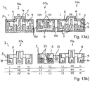
- Figures 13a) and 13b ) can detect combinations of connector sets, in which z. B. the connector 1 according to FIG. 1a ) and the corresponding mating connector 7 FIG. 1b ) is used for the main power supply.
- a three-phase connection is made possible by providing the connector 1 provided with the second functional area 11b for the data supply according to FIG. 2a ) and associated mating connector 7 of FIG. 2b ) is used.
- the mating connector 7 is used as a power plug and the contact elements 10 of the left-hand functional area 11b with further phases L1, L2 and L3 acted upon.
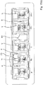
- Figure 14a shows a perspective view of a connector 1, in which the plug-in area projecting outer walls 26 of the insulating housing 2 are contoured to form sleeve shafts 3.
- the plug-in area projecting outer walls 26 of the insulating housing 2 are contoured to form sleeve shafts 3.
- two functional areas 11a, 11b are provided, wherein the first functional area 11a according to the embodiment in FIG. 2a ) is provided to the power voltage supply and the second functional area 11b for a data bus for control.
- flat contact elements 5 are installed, which partially protrude into the contoured Kodierstege 4 and are supported by them.
- the flat contact elements 5, also called blade contacts, have in the illustrated embodiment, an upwardly projecting Vorcardzone 27, the first contact in a lying between the free ends with the contact groups and a root portion of the fork contact elements of a mating connector 7 Vorcardzone 40. In this way it is ensured that possible short-circuit sparks jump over the area of the pre-contact zones 27 and 40 and the main contact zones 28 and 15 are protected and protected against burn-up.
- the distance of the adjacent contact elements 5 of the two functional areas 11a, 11b is greater than the distance of the contact elements 5 within the functional areas 11a, 11b.
- the division within the functional areas 11a, 11b is thus different than the division between the functional areas 11a, 11b.
- the blade contact elements 5 are guided downwards into a conductor connection region 29 with conductor insertion openings 30, wherein here double connections are provided for connection in each case of two electrical conductors to a blade contact element 5.
- This can be a continuous (looping) realize wiring.
- the illustrated connector 1 is particularly suitable as a device connector for a device connector. To connect an electrical device is This device plug (connector 1) then attached to a power plug (mating connector 7).
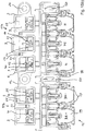
- FIG. 14b shows a perspective view of an embodiment of a five-pole mating connector 7 with two functional areas 11a, 11b.
- the left functional area 11a has two fork contact elements 10 arranged next to one another, while the right functional area 11a has three fork contact elements 10 arranged next to one another.
- the fork contact elements 10 have in a conventional manner two adjacent and a common plane spanning fork tines 14 to form a gap to insert a blade contact element between the forks 14. The associated blade contact element 5 is then contacted by the contact tips 15 on the forks 14.
- the fork contact elements 10 extend into a conductor connection region 16 and are routed there to conductor connection terminals. These can for example be designed as spring-loaded terminals and in particular as multiple spring-loaded terminals, as shown, for. For example, as shown, at least two electrical conductors inserted in juxtaposed conductor insertion openings 17 can contact a fork contact element 10.
- the mating connector 7 is provided as a power plug for fixed installation in an electrical device and has this fasteners 20 z. B. in the form of holes on flat bars, where the mating connector 7 can be screwed or riveted to a device housing. Alternatively, the Power plug via the locking tabs 50 (see Fig. 14b )) are snapped onto a corresponding device sheet.
- the mating connector 7 is particularly suitable for installation in lights, wherein the power plug (mating connector 7) is connected via the connected electrical leads to a power supply and possibly also to a data bus.
- the insulating material housing 2 is recognizably contoured.
- square shafts 22 are formed, wherein the central shaft of the first functional area 11a is longer than the other shafts 22.
- the fork contact element 10 is provided for the PE contact (protection mass).
- the shafts 22 are connected to each other via webs 23, so that the contour of the shafts 22 and the width and position of the webs 23 predetermine a Kodierkontur that allows plugging a connector 1 only in a thereto adapted configuration and location.
- 22 coding shafts 24 are introduced with a contour within the shafts, which are adapted to the corresponding contoured Kodierstege the associated mating connector 1.
- FIG. 15a leaves a top view of the connector 1 Figure 14a ) and FIG. 2a ) detect. It is again clear that the contoured Kodierstege 4 protrude as separate elements integral with the insulating housing 2 in the interior of the socket shafts 3 and the blade contact elements 5 z. B. fix with a kinked holding portion 31 and carry.
- the contoured Kodierstege in cross section a Longitudinal section 32 which extends in the direction of arrangement of the blade contact elements 5, and a subsequent thereto transverse portion 33 extending transversely thereto and in suitcaseeckungsraum the fork contacts 10 of the corresponding mating connector 7.
- the length of the transverse section 33 of the middle bushing of the first functional area 11a is longer than the other transverse sections 33. This is used in the illustrated embodiment, in particular for the protection of a PE contact terminal, which is provided for this area.
- FIG. 15b leaves a top view of the mating connector 7 FIG. 14b ) and FIG. 2b ) detect. From this top view it is again clear that the blade contact elements 5 of the connector 1 is inserted transversely to the plane spanned by the fork tines 14 level in the fork contact elements 10. Due to the above pre-contact zone 27 of the blade contact elements 5 of the connector 1, this pre-contact zone 40 is first contacted at opposing pre-contact groups 40 of the mating connector 7, which are arranged between the actual main contact groups 15 and the unrecognizable common root area of the forks 14 , The main contact with complete insertion of the connector 1 off Figure 14a ) and 15a ) in the mating connector 7 FIG. 14b ) and 15b ) is then carried out with the aid of the main contact groups 15, which are arranged adjacent to the free ends of the fork tines 14. This achieves a burn-free main contact zone.
- the main contact groups 15 have a smaller gap than the pre-contact groups 40, ie that the gap between the pre-contact groups 40 is greater than the gap between the main contact groups. This ensures that when the main contact is reached by the main contact groups 15, only there is an electrical contact with the blade contact elements 5 and the parallel connection is lifted with the pre-contact groups 40.
- FIG. 16 reveals a perspective view of an additional separate contact element 34.
- This has a cuboid main section 35, from the z. B. a pair of adjacent and parallel to each other réellekender coding fingers 36 protrude.
- the main portion 35 has lateral guide grooves 37, in which the proper insertion into associated shafts 22 of the mating connector 7, the webs provided there dip 25. This ensures a correct position of the coding element 34 in the shaft 22.
- the coding element 34 can be introduced in a direction-oriented position, wherein in this coding position, the coding fingers 36 dive into the Kodierstege 4 of a connector 1 adapted Kodierwirchte 9 a mating connector 7 and block them partially.
- an actuation slot 38 is provided on an edge of the main body 35, in which an actuating tool, such as a screwdriver can be introduced. Then, the coding element 35 can be levered out with the screwdriver 38 on the insulating 2 of the mating connector 7.
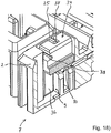
- FIG. 17 omits a perspective view of a coding element 34 FIG. 16 ) just before plugging into a coding shaft 9 of a mating connector 7 recognize. It is clear that the coding fingers 36 protrude with their free ends in the interior of the Kodierschachts 9 and the main body 35 is disposed above it.
- FIG. 18 omits a partial sectional view of the mating connector 7 FIG. 17 ) with plugged coding element 34.
- the coding shaft 9 of the mating connector 7 is partially executed and blocked by the coding fingers 36.
- Also located below the coding element 34 fork contact element 10 is covered by the overlying coding element 34 and leaves a contact with a blade contact element 5 of a connector 1 no longer closed.
- connection area is thus functionless and protected against miscarriage.
- the coding element 34 is guided with the grooves 37 on the webs 25. Furthermore, the function of the actuating slot 38 becomes clearer, which is accessible from above through a slot and allows levering out of the coding element 34 with a screwdriver over the upper edge of the insulating housing 2 of the mating connector 7.
Landscapes
- Details Of Connecting Devices For Male And Female Coupling (AREA)
- Coupling Device And Connection With Printed Circuit (AREA)
Claims (11)
- Ensemble de connexion par enfichage, comprenant une fiche de connexion (1) et une fiche de connexion homologue (7), lesquelles comprennent respectivement un boîtier en matériau isolant (2, 8) et des éléments de contact (5, 10) intégrés dans le boîtier en matériau isolant (2, 8), la fiche de connexion (1) et la fiche de connexion homologue (7) étant configurées pour établir un contact électriquement conducteur entre les éléments de contact (5, 10) associés lors de l'enfichage mutuel de la fiche de connexion (1) et de la fiche de connexion homologue (7) en correspondance l'une avec l'autre, et les boîtiers en matériau isolant (2, 8) ayant un profil de codage qui n'autorise l'enfichage mutuel que dans une position admissible de la fiche de connexion (1) et de la fiche de connexion homologue (7) l'une par rapport à l'autre, la fiche de connexion (1) et/ou la fiche de connexion homologue (7) comprenant au moins deux zones fonctionnelles (11a, 11b, 11c) comportant respectivement au moins deux éléments de contact (5, 10) disposés l'un à côté de l'autre dans une portion de boîtier en matériau isolant et que les éléments de contact (5, 10) disposés l'un à côté de l'autre de deux zones fonctionnelles (11a, 11b, 11c) voisines présentent un écart entre eux qui est différent de l'écart entre les éléments de contact (5, 10) respectivement présents dans ces zones fonctionnelles, caractérisé en ce que pour le codage de l'ensemble de connexion par enfichage, le boîtier en matériau isolant (2) de la fiche de connexion (1) comprend des logements formant douille (3) formés par des parois extérieures profilées du boîtier en matériau isolant (2) et des nervures de codage (4) faisant saillie dans le sens de l'enfichage dans l'espace intérieur des logements formant douille (3), et en ce que le boîtier en matériau isolant (8) de la fiche de connexion homologue (7) possède des logements de codage (9) adaptés destinés à accueillir des nervures de codage (4) profilées correspondantes dans une seule position d'enfichage admissible, les nervures de codage (4) profilées de la fiche de connexion (1) possédant des formes différentes les unes des autres.
- Ensemble de connexion par enfichage selon la revendication 1, caractérisé en ce que les éléments de contact (5) sont partiellement accueillis dans les nervures de codage (4).
- Ensemble de connexion par enfichage selon la revendication 1 ou 2, caractérisé en ce que les nervures de codage (4) comprennent une portion longitudinale (32) qui s'étend dans le sens de l'alignement des éléments de contact (5) et une portion transversale (33) qui fait saillie depuis celle-ci, et en ce que la portion transversale (33), en vue du codage, est disposée latéralement à gauche, au centre ou latéralement à droite par rapport à la portion longitudinale (32).
- Ensemble de connexion par enfichage selon l'une des revendications précédentes, caractérisé en ce que les portions de boîtier en matériau isolant des zones fonctionnelles (11a, 11b, 11c) de la fiche de connexion homologue (7) sont reliées entre elles par des nervures de liaison (12), et des cavités (6) adaptées aux nervures de liaison (12), destinées à accueillir des nervures de liaison (12) associées lors de l'enfichage mutuel de la fiche de connexion (1) et de la fiche de connexion homologue (7) dans une position d'enfichage admissible unique, sont présentes dans des parois extérieures des portions de boîtier en matériau isolant des zones fonctionnelles (11a, 11b, 11c) de la fiche de connexion (1).
- Ensemble de connexion par enfichage selon l'une des revendications précédentes, caractérisé en ce que les éléments de contact (5, 10) sont configurés par paires sous la forme de contacts à fourche (10) comprenant une paire de dents de fourche (14) opposées et sous la forme de contacts à lame (5) plats correspondants.
- Ensemble de connexion par enfichage selon la revendication 5, caractérisé en ce que les contacts à fourche (10) sont incorporés dans le boîtier en matériau isolant (8) associé transversalement au sens de l'enfichage de telle sorte que les contacts à lame (5) puissent être introduits dans un interstice formé par les dents de fourche (14) lors de l'enfichage mutuel transversalement au plan couvert par les dents de fourche (14) des contacts à fourche.
- Ensemble de connexion par enfichage selon l'une des revendications précédentes, caractérisé en ce que le boîtier en matériau isolant (2, 8) est plus long dans la zone d'un contact de terre de protection (PE) que dans les autres zones.
- Ensemble de connexion par enfichage selon l'une des revendications précédentes, caractérisé en ce que des éléments de codage (34) séparés, qui peuvent être insérés dans des logements formant douille (3, 22), sont présents, les éléments de codage possédant au moins un picot de codage (36) en saillie.
- Fiche de connexion (1) pour un ensemble de connexion par enfichage selon l'une des revendications précédentes, caractérisée en ce que la fiche de connexion (1) comprend au moins deux zones fonctionnelles (11a, 11b, 11c) comportant respectivement au moins deux éléments de contact (5) disposés l'un à côté de l'autre dans une portion de boîtier en matériau isolant, et en ce que les éléments de contact disposés l'un à côté de l'autre de deux zones fonctionnelles (11a, 11b, 11c) voisines présentent un écart entre eux qui est différent de l'écart entre les éléments de contact (5) respectivement présents dans ces zones fonctionnelles (11a, 11b, 11c).
- Fiche de connexion homologue (7) pour un ensemble de connexion par enfichage selon l'une des revendications 1 à 8, caractérisée en ce que la fiche de connexion homologue comprend au moins deux zones fonctionnelles (11a, 11b, 11c) comportant respectivement au moins deux éléments de contact (10) disposés l'un à côté de l'autre dans une portion de boîtier en matériau isolant, et en ce que les éléments de contact (10) disposés l'un à côté de l'autre de deux zones fonctionnelles (11a, 11b, 11c) voisines présentent un écart entre eux qui est différent de l'écart entre les éléments de contact (10) respectivement présents dans ces zones fonctionnelles (11a, 11b, 11c).
- Fiche de connexion (1) selon la revendication 9, comprenant un boîtier en matériau isolant (2) profilé au niveau du pourtour extérieur qui comprend des logements formant douille (3) profilés formés par des parois du boîtier en matériau isolant (2), et comprenant des éléments de contact (5) dans le boîtier en matériau isolant (2), caractérisée en ce que des éléments de codage (34) insérables sont présents dans les logements formant douille (3, 22), les éléments de codage (34) possédant au moins un picot de codage (36) en saillie.
Applications Claiming Priority (2)
| Application Number | Priority Date | Filing Date | Title |
|---|---|---|---|
| DE102012103216A DE102012103216A1 (de) | 2012-04-13 | 2012-04-13 | Steckverbinderset und Steckverbinder und Gegensteckverbinder hierzu |
| PCT/EP2013/057473 WO2013153105A1 (fr) | 2012-04-13 | 2013-04-10 | Ensemble de connexion, et connecteur et connecteur antagoniste correspondants |
Publications (2)
| Publication Number | Publication Date |
|---|---|
| EP2837064A1 EP2837064A1 (fr) | 2015-02-18 |
| EP2837064B1 true EP2837064B1 (fr) | 2018-08-01 |
Family
ID=48050741
Family Applications (1)
| Application Number | Title | Priority Date | Filing Date |
|---|---|---|---|
| EP13714949.8A Not-in-force EP2837064B1 (fr) | 2012-04-13 | 2013-04-10 | Ensemble de connexion, et connecteur et connecteur antagoniste correspondants |
Country Status (5)
| Country | Link |
|---|---|
| EP (1) | EP2837064B1 (fr) |
| JP (1) | JP2015516655A (fr) |
| CN (1) | CN104303367A (fr) |
| DE (1) | DE102012103216A1 (fr) |
| WO (1) | WO2013153105A1 (fr) |
Cited By (1)
| Publication number | Priority date | Publication date | Assignee | Title |
|---|---|---|---|---|
| US12176651B2 (en) | 2020-06-18 | 2024-12-24 | Ideal Industries, Inc. | Conductor terminal |
Families Citing this family (2)
| Publication number | Priority date | Publication date | Assignee | Title |
|---|---|---|---|---|
| JP6747767B2 (ja) * | 2014-11-11 | 2020-08-26 | フクダ電子株式会社 | コネクタ |
| DE102020000422A1 (de) | 2020-01-24 | 2021-07-29 | Drägerwerk AG & Co. KGaA | Elektrische Steckverbindung für eine Medizingeräteanordnung |
Citations (1)
| Publication number | Priority date | Publication date | Assignee | Title |
|---|---|---|---|---|
| US6146150A (en) * | 1998-11-24 | 2000-11-14 | International Business Machines Corporation | Circuit card with separate interfaces for different bus architectures |
Family Cites Families (16)
| Publication number | Priority date | Publication date | Assignee | Title |
|---|---|---|---|---|
| JPS59195679U (ja) * | 1983-06-13 | 1984-12-26 | 和泉電気株式会社 | 接触子装置 |
| JPS60236474A (ja) * | 1984-05-10 | 1985-11-25 | 日本電気株式会社 | コネクタ |
| US5356300A (en) * | 1993-09-16 | 1994-10-18 | The Whitaker Corporation | Blind mating guides with ground contacts |
| JPH09245909A (ja) * | 1996-03-05 | 1997-09-19 | Sanyo Electric Works Ltd | インバータ式サイン灯用電源装置 |
| DE19932243A1 (de) * | 1999-07-06 | 2001-01-11 | Wago Verwaltungs Gmbh | Elektrischer Steckverbinder |
| JP3549190B2 (ja) * | 2000-11-10 | 2004-08-04 | Smk株式会社 | 多極コネクタ用レセプタクル |
| JP2002352898A (ja) * | 2001-05-25 | 2002-12-06 | Tyco Electronics Amp Kk | シャッタ付電気コネクタおよび電気コネクタ組立体 |
| US6540549B2 (en) * | 2001-06-14 | 2003-04-01 | Dekko Engineering, Inc. | Keyed power cord |
| JP4184937B2 (ja) * | 2003-11-28 | 2008-11-19 | 矢崎総業株式会社 | レバー嵌合式コネクタ |
| TWM266609U (en) * | 2004-07-16 | 2005-06-01 | Hon Hai Prec Ind Co Ltd | Electrical connector assembly |
| US7160141B2 (en) * | 2004-10-26 | 2007-01-09 | Fci Americas Technology, Inc. | Low-profile, high speed, board-to-board connector system |
| ITTO20060228A1 (it) * | 2006-03-28 | 2007-09-29 | Tyco Electronics Amp Italia Spa | Connettore elettrico con elementi di chiusura |
| DE202007002248U1 (de) * | 2007-02-15 | 2007-06-06 | Harting Electric Gmbh & Co. Kg | Kodiereinrichtung für Steckverbinder |
| JP2010055896A (ja) * | 2008-08-27 | 2010-03-11 | Panasonic Electric Works Co Ltd | コンセント、プラグ及び配線装置 |
| DE102008049574A1 (de) | 2008-09-30 | 2010-04-01 | Phoenix Contact Gmbh & Co. Kg | Elektrisches Steckverbindungssystem |
| DE102008054015B4 (de) * | 2008-10-30 | 2012-11-08 | Lumberg Connect Gmbh | Steckverbinder |
-
2012
- 2012-04-13 DE DE102012103216A patent/DE102012103216A1/de not_active Withdrawn
-
2013
- 2013-04-10 JP JP2015504939A patent/JP2015516655A/ja active Pending
- 2013-04-10 WO PCT/EP2013/057473 patent/WO2013153105A1/fr not_active Ceased
- 2013-04-10 EP EP13714949.8A patent/EP2837064B1/fr not_active Not-in-force
- 2013-04-10 CN CN201380024993.XA patent/CN104303367A/zh active Pending
Patent Citations (1)
| Publication number | Priority date | Publication date | Assignee | Title |
|---|---|---|---|---|
| US6146150A (en) * | 1998-11-24 | 2000-11-14 | International Business Machines Corporation | Circuit card with separate interfaces for different bus architectures |
Cited By (1)
| Publication number | Priority date | Publication date | Assignee | Title |
|---|---|---|---|---|
| US12176651B2 (en) | 2020-06-18 | 2024-12-24 | Ideal Industries, Inc. | Conductor terminal |
Also Published As
| Publication number | Publication date |
|---|---|
| CN104303367A (zh) | 2015-01-21 |
| DE102012103216A1 (de) | 2013-10-17 |
| JP2015516655A (ja) | 2015-06-11 |
| EP2837064A1 (fr) | 2015-02-18 |
| DE102012103216A9 (de) | 2014-06-12 |
| WO2013153105A1 (fr) | 2013-10-17 |
Similar Documents
| Publication | Publication Date | Title |
|---|---|---|
| EP3345255B1 (fr) | Système constitué d'un cadre modulaire de connecteur enfichable et d'éléments adaptateurs | |
| EP2715871B1 (fr) | Dispositif de contrôle et de connexion | |
| EP3293833B1 (fr) | Connecteur de rails d'alimentation | |
| EP2058904B1 (fr) | Connecteur à fiches hermaphrodite | |
| EP3196981B1 (fr) | Connecteur transversal pour bornier | |
| EP3276757A1 (fr) | Connecteur de rail de connexion et kit constitué de deux connecteurs de rail de connexion complémentaires et auges métalliques comprenant respectivement un profilé d'amenée de courant disposé en son sein | |
| EP3718175B1 (fr) | Connecteur enfichable et système de connecteurs enfichables pourvu d'un tel connecteur enfichable | |
| EP0865105B1 (fr) | Douille de connexion électrique avec ressort de contact et douille utilisable comme contact terminal | |
| EP2837064B1 (fr) | Ensemble de connexion, et connecteur et connecteur antagoniste correspondants | |
| EP2671286B1 (fr) | Bloc de distributeur | |
| EP2600470B1 (fr) | Dispositif de raccordement pour un câble plat et appareil électrique doté d'un câble plat raccordé | |
| DE102008025433B4 (de) | Klemmenanschlußblock | |
| EP3172802A1 (fr) | Connecteur enfichable | |
| DE102015224595A1 (de) | Gedruckte-Leiterplatten-Einheit mit verbesserten Anschlüssen | |
| EP3066723B1 (fr) | Câble d'essai ainsi qu'adaptateur de prise pour un câble d'essai | |
| DE102014114352B3 (de) | Stiftleiste | |
| DE102012103214B4 (de) | Schaltverteiler und Anordnung aus Schaltverteiler und daran angeschlossener Schalteinheit | |
| DE10013241B4 (de) | Elektrischer Querbrücker | |
| EP1763111B1 (fr) | Contact à douille avec au moins deux points de contact dans la direction de connexion | |
| DE102022210025B3 (de) | Vorrichtung zur Leistungsverteilung für ein Kraftfahrzeug sowie modularer Stecker für eine solche Vorrichtung | |
| EP3033809B1 (fr) | Codage d'embases comprenant une pluralité de compartiments | |
| EP2759024A1 (fr) | Élément à enfichage | |
| DE202025102463U1 (de) | Schutzkontaktsteckdose | |
| EP1503456B1 (fr) | Connecteur électrique plus particulièrement avec fiche ronde | |
| WO2023012232A1 (fr) | Connecteur comprenant des éléments koshiri en tant qu'extension de codage |
Legal Events
| Date | Code | Title | Description |
|---|---|---|---|
| PUAI | Public reference made under article 153(3) epc to a published international application that has entered the european phase |
Free format text: ORIGINAL CODE: 0009012 |
|
| 17P | Request for examination filed |
Effective date: 20140922 |
|
| AK | Designated contracting states |
Kind code of ref document: A1 Designated state(s): AL AT BE BG CH CY CZ DE DK EE ES FI FR GB GR HR HU IE IS IT LI LT LU LV MC MK MT NL NO PL PT RO RS SE SI SK SM TR |
|
| AX | Request for extension of the european patent |
Extension state: BA ME |
|
| DAX | Request for extension of the european patent (deleted) | ||
| 17Q | First examination report despatched |
Effective date: 20160329 |
|
| STAA | Information on the status of an ep patent application or granted ep patent |
Free format text: STATUS: EXAMINATION IS IN PROGRESS |
|
| GRAP | Despatch of communication of intention to grant a patent |
Free format text: ORIGINAL CODE: EPIDOSNIGR1 |
|
| STAA | Information on the status of an ep patent application or granted ep patent |
Free format text: STATUS: GRANT OF PATENT IS INTENDED |
|
| INTG | Intention to grant announced |
Effective date: 20180222 |
|
| GRAS | Grant fee paid |
Free format text: ORIGINAL CODE: EPIDOSNIGR3 |
|
| GRAJ | Information related to disapproval of communication of intention to grant by the applicant or resumption of examination proceedings by the epo deleted |
Free format text: ORIGINAL CODE: EPIDOSDIGR1 |
|
| GRAL | Information related to payment of fee for publishing/printing deleted |
Free format text: ORIGINAL CODE: EPIDOSDIGR3 |
|
| STAA | Information on the status of an ep patent application or granted ep patent |
Free format text: STATUS: EXAMINATION IS IN PROGRESS |
|
| GRAP | Despatch of communication of intention to grant a patent |
Free format text: ORIGINAL CODE: EPIDOSNIGR1 |
|
| STAA | Information on the status of an ep patent application or granted ep patent |
Free format text: STATUS: GRANT OF PATENT IS INTENDED |
|
| INTC | Intention to grant announced (deleted) | ||
| GRAA | (expected) grant |
Free format text: ORIGINAL CODE: 0009210 |
|
| STAA | Information on the status of an ep patent application or granted ep patent |
Free format text: STATUS: THE PATENT HAS BEEN GRANTED |
|
| INTG | Intention to grant announced |
Effective date: 20180614 |
|
| AK | Designated contracting states |
Kind code of ref document: B1 Designated state(s): AL AT BE BG CH CY CZ DE DK EE ES FI FR GB GR HR HU IE IS IT LI LT LU LV MC MK MT NL NO PL PT RO RS SE SI SK SM TR |
|
| REG | Reference to a national code |
Ref country code: GB Ref legal event code: FG4D Free format text: NOT ENGLISH |
|
| REG | Reference to a national code |
Ref country code: CH Ref legal event code: EP Ref country code: AT Ref legal event code: REF Ref document number: 1025428 Country of ref document: AT Kind code of ref document: T Effective date: 20180815 |
|
| REG | Reference to a national code |
Ref country code: IE Ref legal event code: FG4D Free format text: LANGUAGE OF EP DOCUMENT: GERMAN |
|
| REG | Reference to a national code |
Ref country code: DE Ref legal event code: R096 Ref document number: 502013010732 Country of ref document: DE |
|
| REG | Reference to a national code |
Ref country code: NL Ref legal event code: MP Effective date: 20180801 |
|
| REG | Reference to a national code |
Ref country code: LT Ref legal event code: MG4D |
|
| PG25 | Lapsed in a contracting state [announced via postgrant information from national office to epo] |
Ref country code: PL Free format text: LAPSE BECAUSE OF FAILURE TO SUBMIT A TRANSLATION OF THE DESCRIPTION OR TO PAY THE FEE WITHIN THE PRESCRIBED TIME-LIMIT Effective date: 20180801 Ref country code: LT Free format text: LAPSE BECAUSE OF FAILURE TO SUBMIT A TRANSLATION OF THE DESCRIPTION OR TO PAY THE FEE WITHIN THE PRESCRIBED TIME-LIMIT Effective date: 20180801 Ref country code: RS Free format text: LAPSE BECAUSE OF FAILURE TO SUBMIT A TRANSLATION OF THE DESCRIPTION OR TO PAY THE FEE WITHIN THE PRESCRIBED TIME-LIMIT Effective date: 20180801 Ref country code: IS Free format text: LAPSE BECAUSE OF FAILURE TO SUBMIT A TRANSLATION OF THE DESCRIPTION OR TO PAY THE FEE WITHIN THE PRESCRIBED TIME-LIMIT Effective date: 20181201 Ref country code: BG Free format text: LAPSE BECAUSE OF FAILURE TO SUBMIT A TRANSLATION OF THE DESCRIPTION OR TO PAY THE FEE WITHIN THE PRESCRIBED TIME-LIMIT Effective date: 20181101 Ref country code: NL Free format text: LAPSE BECAUSE OF FAILURE TO SUBMIT A TRANSLATION OF THE DESCRIPTION OR TO PAY THE FEE WITHIN THE PRESCRIBED TIME-LIMIT Effective date: 20180801 Ref country code: NO Free format text: LAPSE BECAUSE OF FAILURE TO SUBMIT A TRANSLATION OF THE DESCRIPTION OR TO PAY THE FEE WITHIN THE PRESCRIBED TIME-LIMIT Effective date: 20181101 Ref country code: FI Free format text: LAPSE BECAUSE OF FAILURE TO SUBMIT A TRANSLATION OF THE DESCRIPTION OR TO PAY THE FEE WITHIN THE PRESCRIBED TIME-LIMIT Effective date: 20180801 Ref country code: GR Free format text: LAPSE BECAUSE OF FAILURE TO SUBMIT A TRANSLATION OF THE DESCRIPTION OR TO PAY THE FEE WITHIN THE PRESCRIBED TIME-LIMIT Effective date: 20181102 Ref country code: SE Free format text: LAPSE BECAUSE OF FAILURE TO SUBMIT A TRANSLATION OF THE DESCRIPTION OR TO PAY THE FEE WITHIN THE PRESCRIBED TIME-LIMIT Effective date: 20180801 |
|
| PG25 | Lapsed in a contracting state [announced via postgrant information from national office to epo] |
Ref country code: HR Free format text: LAPSE BECAUSE OF FAILURE TO SUBMIT A TRANSLATION OF THE DESCRIPTION OR TO PAY THE FEE WITHIN THE PRESCRIBED TIME-LIMIT Effective date: 20180801 Ref country code: AL Free format text: LAPSE BECAUSE OF FAILURE TO SUBMIT A TRANSLATION OF THE DESCRIPTION OR TO PAY THE FEE WITHIN THE PRESCRIBED TIME-LIMIT Effective date: 20180801 Ref country code: LV Free format text: LAPSE BECAUSE OF FAILURE TO SUBMIT A TRANSLATION OF THE DESCRIPTION OR TO PAY THE FEE WITHIN THE PRESCRIBED TIME-LIMIT Effective date: 20180801 |
|
| PG25 | Lapsed in a contracting state [announced via postgrant information from national office to epo] |
Ref country code: IT Free format text: LAPSE BECAUSE OF FAILURE TO SUBMIT A TRANSLATION OF THE DESCRIPTION OR TO PAY THE FEE WITHIN THE PRESCRIBED TIME-LIMIT Effective date: 20180801 Ref country code: CZ Free format text: LAPSE BECAUSE OF FAILURE TO SUBMIT A TRANSLATION OF THE DESCRIPTION OR TO PAY THE FEE WITHIN THE PRESCRIBED TIME-LIMIT Effective date: 20180801 Ref country code: RO Free format text: LAPSE BECAUSE OF FAILURE TO SUBMIT A TRANSLATION OF THE DESCRIPTION OR TO PAY THE FEE WITHIN THE PRESCRIBED TIME-LIMIT Effective date: 20180801 Ref country code: EE Free format text: LAPSE BECAUSE OF FAILURE TO SUBMIT A TRANSLATION OF THE DESCRIPTION OR TO PAY THE FEE WITHIN THE PRESCRIBED TIME-LIMIT Effective date: 20180801 Ref country code: ES Free format text: LAPSE BECAUSE OF FAILURE TO SUBMIT A TRANSLATION OF THE DESCRIPTION OR TO PAY THE FEE WITHIN THE PRESCRIBED TIME-LIMIT Effective date: 20180801 |
|
| REG | Reference to a national code |
Ref country code: DE Ref legal event code: R097 Ref document number: 502013010732 Country of ref document: DE |
|
| PG25 | Lapsed in a contracting state [announced via postgrant information from national office to epo] |
Ref country code: SM Free format text: LAPSE BECAUSE OF FAILURE TO SUBMIT A TRANSLATION OF THE DESCRIPTION OR TO PAY THE FEE WITHIN THE PRESCRIBED TIME-LIMIT Effective date: 20180801 Ref country code: DK Free format text: LAPSE BECAUSE OF FAILURE TO SUBMIT A TRANSLATION OF THE DESCRIPTION OR TO PAY THE FEE WITHIN THE PRESCRIBED TIME-LIMIT Effective date: 20180801 Ref country code: SK Free format text: LAPSE BECAUSE OF FAILURE TO SUBMIT A TRANSLATION OF THE DESCRIPTION OR TO PAY THE FEE WITHIN THE PRESCRIBED TIME-LIMIT Effective date: 20180801 |
|
| PLBE | No opposition filed within time limit |
Free format text: ORIGINAL CODE: 0009261 |
|
| STAA | Information on the status of an ep patent application or granted ep patent |
Free format text: STATUS: NO OPPOSITION FILED WITHIN TIME LIMIT |
|
| 26N | No opposition filed |
Effective date: 20190503 |
|
| PG25 | Lapsed in a contracting state [announced via postgrant information from national office to epo] |
Ref country code: SI Free format text: LAPSE BECAUSE OF FAILURE TO SUBMIT A TRANSLATION OF THE DESCRIPTION OR TO PAY THE FEE WITHIN THE PRESCRIBED TIME-LIMIT Effective date: 20180801 |
|
| REG | Reference to a national code |
Ref country code: DE Ref legal event code: R119 Ref document number: 502013010732 Country of ref document: DE |
|
| REG | Reference to a national code |
Ref country code: CH Ref legal event code: PL |
|
| REG | Reference to a national code |
Ref country code: BE Ref legal event code: MM Effective date: 20190430 |
|
| GBPC | Gb: european patent ceased through non-payment of renewal fee |
Effective date: 20190410 |
|
| PG25 | Lapsed in a contracting state [announced via postgrant information from national office to epo] |
Ref country code: LU Free format text: LAPSE BECAUSE OF NON-PAYMENT OF DUE FEES Effective date: 20190410 Ref country code: MC Free format text: LAPSE BECAUSE OF FAILURE TO SUBMIT A TRANSLATION OF THE DESCRIPTION OR TO PAY THE FEE WITHIN THE PRESCRIBED TIME-LIMIT Effective date: 20180801 |
|
| PG25 | Lapsed in a contracting state [announced via postgrant information from national office to epo] |
Ref country code: CH Free format text: LAPSE BECAUSE OF NON-PAYMENT OF DUE FEES Effective date: 20190430 Ref country code: LI Free format text: LAPSE BECAUSE OF NON-PAYMENT OF DUE FEES Effective date: 20190430 Ref country code: DE Free format text: LAPSE BECAUSE OF NON-PAYMENT OF DUE FEES Effective date: 20191101 Ref country code: GB Free format text: LAPSE BECAUSE OF NON-PAYMENT OF DUE FEES Effective date: 20190410 |
|
| PG25 | Lapsed in a contracting state [announced via postgrant information from national office to epo] |
Ref country code: FR Free format text: LAPSE BECAUSE OF NON-PAYMENT OF DUE FEES Effective date: 20190430 Ref country code: BE Free format text: LAPSE BECAUSE OF NON-PAYMENT OF DUE FEES Effective date: 20190430 |
|
| PG25 | Lapsed in a contracting state [announced via postgrant information from national office to epo] |
Ref country code: TR Free format text: LAPSE BECAUSE OF FAILURE TO SUBMIT A TRANSLATION OF THE DESCRIPTION OR TO PAY THE FEE WITHIN THE PRESCRIBED TIME-LIMIT Effective date: 20180801 |
|
| PG25 | Lapsed in a contracting state [announced via postgrant information from national office to epo] |
Ref country code: IE Free format text: LAPSE BECAUSE OF NON-PAYMENT OF DUE FEES Effective date: 20190410 |
|
| PG25 | Lapsed in a contracting state [announced via postgrant information from national office to epo] |
Ref country code: PT Free format text: LAPSE BECAUSE OF FAILURE TO SUBMIT A TRANSLATION OF THE DESCRIPTION OR TO PAY THE FEE WITHIN THE PRESCRIBED TIME-LIMIT Effective date: 20181201 |
|
| REG | Reference to a national code |
Ref country code: AT Ref legal event code: MM01 Ref document number: 1025428 Country of ref document: AT Kind code of ref document: T Effective date: 20190410 |
|
| PG25 | Lapsed in a contracting state [announced via postgrant information from national office to epo] |
Ref country code: AT Free format text: LAPSE BECAUSE OF NON-PAYMENT OF DUE FEES Effective date: 20190410 |
|
| PG25 | Lapsed in a contracting state [announced via postgrant information from national office to epo] |
Ref country code: CY Free format text: LAPSE BECAUSE OF FAILURE TO SUBMIT A TRANSLATION OF THE DESCRIPTION OR TO PAY THE FEE WITHIN THE PRESCRIBED TIME-LIMIT Effective date: 20180801 |
|
| PG25 | Lapsed in a contracting state [announced via postgrant information from national office to epo] |
Ref country code: HU Free format text: LAPSE BECAUSE OF FAILURE TO SUBMIT A TRANSLATION OF THE DESCRIPTION OR TO PAY THE FEE WITHIN THE PRESCRIBED TIME-LIMIT; INVALID AB INITIO Effective date: 20130410 Ref country code: MT Free format text: LAPSE BECAUSE OF FAILURE TO SUBMIT A TRANSLATION OF THE DESCRIPTION OR TO PAY THE FEE WITHIN THE PRESCRIBED TIME-LIMIT Effective date: 20180801 |
|
| PG25 | Lapsed in a contracting state [announced via postgrant information from national office to epo] |
Ref country code: MK Free format text: LAPSE BECAUSE OF FAILURE TO SUBMIT A TRANSLATION OF THE DESCRIPTION OR TO PAY THE FEE WITHIN THE PRESCRIBED TIME-LIMIT Effective date: 20180801 |