EP2837536B2 - Vorrichtung zum Entmanteln eines Rohrendes einer mit einer Kunststoffbeschichtung beschichteten Brems- oder Kraftstoffleitung - Google Patents
Vorrichtung zum Entmanteln eines Rohrendes einer mit einer Kunststoffbeschichtung beschichteten Brems- oder Kraftstoffleitung Download PDFInfo
- Publication number
- EP2837536B2 EP2837536B2 EP14174058.9A EP14174058A EP2837536B2 EP 2837536 B2 EP2837536 B2 EP 2837536B2 EP 14174058 A EP14174058 A EP 14174058A EP 2837536 B2 EP2837536 B2 EP 2837536B2
- Authority
- EP
- European Patent Office
- Prior art keywords
- pipe end
- plastic coating
- roller
- pressure
- coating
- Prior art date
- Legal status (The legal status is an assumption and is not a legal conclusion. Google has not performed a legal analysis and makes no representation as to the accuracy of the status listed.)
- Active
Links
Images


Classifications
-
- B—PERFORMING OPERATIONS; TRANSPORTING
- B23—MACHINE TOOLS; METAL-WORKING NOT OTHERWISE PROVIDED FOR
- B23D—PLANING; SLOTTING; SHEARING; BROACHING; SAWING; FILING; SCRAPING; LIKE OPERATIONS FOR WORKING METAL BY REMOVING MATERIAL, NOT OTHERWISE PROVIDED FOR
- B23D79/00—Methods, machines, or devices not covered elsewhere, for working metal by removal of material
- B23D79/12—Machines or devices for peeling bars or tubes making use of cutting bits arranged around the workpiece, otherwise than by turning
-
- B—PERFORMING OPERATIONS; TRANSPORTING
- B60—VEHICLES IN GENERAL
- B60T—VEHICLE BRAKE CONTROL SYSTEMS OR PARTS THEREOF; BRAKE CONTROL SYSTEMS OR PARTS THEREOF, IN GENERAL; ARRANGEMENT OF BRAKING ELEMENTS ON VEHICLES IN GENERAL; PORTABLE DEVICES FOR PREVENTING UNWANTED MOVEMENT OF VEHICLES; VEHICLE MODIFICATIONS TO FACILITATE COOLING OF BRAKES
- B60T17/00—Component parts, details, or accessories of power brake systems not covered by groups B60T8/00, B60T13/00 or B60T15/00, or presenting other characteristic features
- B60T17/04—Arrangements of piping, valves in the piping, e.g. cut-off valves, couplings or air hoses
-
- F—MECHANICAL ENGINEERING; LIGHTING; HEATING; WEAPONS; BLASTING
- F02—COMBUSTION ENGINES; HOT-GAS OR COMBUSTION-PRODUCT ENGINE PLANTS
- F02M—SUPPLYING COMBUSTION ENGINES IN GENERAL WITH COMBUSTIBLE MIXTURES OR CONSTITUENTS THEREOF
- F02M37/00—Apparatus or systems for feeding liquid fuel from storage containers to carburettors or fuel-injection apparatus; Arrangements for purifying liquid fuel specially adapted for, or arranged on, internal-combustion engines
- F02M37/0011—Constructional details; Manufacturing or assembly of elements of fuel systems; Materials therefor
- F02M37/0017—Constructional details; Manufacturing or assembly of elements of fuel systems; Materials therefor related to fuel pipes or their connections, e.g. joints or sealings
-
- F—MECHANICAL ENGINEERING; LIGHTING; HEATING; WEAPONS; BLASTING
- F16—ENGINEERING ELEMENTS AND UNITS; GENERAL MEASURES FOR PRODUCING AND MAINTAINING EFFECTIVE FUNCTIONING OF MACHINES OR INSTALLATIONS; THERMAL INSULATION IN GENERAL
- F16L—PIPES; JOINTS OR FITTINGS FOR PIPES; SUPPORTS FOR PIPES, CABLES OR PROTECTIVE TUBING; MEANS FOR THERMAL INSULATION IN GENERAL
- F16L19/00—Joints in which sealing surfaces are pressed together by means of a member, e.g. a swivel nut, screwed on, or into, one of the joint parts
- F16L19/02—Pipe ends provided with collars or flanges, integral with the pipe or not, pressed together by a screwed member
- F16L19/0243—Pipe ends provided with collars or flanges, integral with the pipe or not, pressed together by a screwed member specially adapted for use with coated pipes
-
- F—MECHANICAL ENGINEERING; LIGHTING; HEATING; WEAPONS; BLASTING
- F16—ENGINEERING ELEMENTS AND UNITS; GENERAL MEASURES FOR PRODUCING AND MAINTAINING EFFECTIVE FUNCTIONING OF MACHINES OR INSTALLATIONS; THERMAL INSULATION IN GENERAL
- F16L—PIPES; JOINTS OR FITTINGS FOR PIPES; SUPPORTS FOR PIPES, CABLES OR PROTECTIVE TUBING; MEANS FOR THERMAL INSULATION IN GENERAL
- F16L19/00—Joints in which sealing surfaces are pressed together by means of a member, e.g. a swivel nut, screwed on, or into, one of the joint parts
- F16L19/02—Pipe ends provided with collars or flanges, integral with the pipe or not, pressed together by a screwed member
- F16L19/025—Pipe ends provided with collars or flanges, integral with the pipe or not, pressed together by a screwed member the pipe ends having integral collars or flanges
- F16L19/028—Pipe ends provided with collars or flanges, integral with the pipe or not, pressed together by a screwed member the pipe ends having integral collars or flanges the collars or flanges being obtained by deformation of the pipe wall
Definitions
- the invention relates to a device for stripping a pipe end of a brake or fuel line coated with a plastic coating according to the preamble of patent claim 1 and a method for stripping the pipe end according to patent claim 10.
- a brake or fuel line can have a multilayer structure, with an inner aluminum or steel tube, a radially outer aluminum or zinc layer for corrosion protection, and a radially outer plastic coating to protect against external mechanical influences.
- Such a brake line has at its tube end in common practice on a flanged head, which can be connected to a brake pressure transducer by means of a union nut.
- a seal nut There are special requirements for the sealing surface of the flare head.
- the sealing surface must be metallically clean and smooth all around, free of cracks and grooves in order to ensure a perfect seal with the pressure transmitter.
- the preparation for carrying out a perfect flanging of the pipe end, in which the plastic coating is to be removed from the pipe end without leaving any residue, is particularly problematic. Plastic particles that may not have been removed from the end of the pipe can pose a significant risk to the functional reliability of the brake system if such plastic particles get into the hydraulic brake circuit during assembly processes.
- a device for stripping a tube end of a brake line is known.
- the device has a scraping tool whose cutting edges peel off the plastic coating in the area of the pipe end without damaging the metal pipe core of the brake line.
- the object of the invention is to provide a device and a method that enable process-reliable stripping of the tube end of the brake or fuel line coated with a plastic coating.
- the invention is based on the problem that when the plastic coating is peeled off, as is known from the prior art, there is a risk of the radially inner metal tube core being damaged by the peeling tool.
- the device according to the invention does not have a peeling tool, but rather at least one pressure element with which the plastic coating can be detached from the tube core by mechanical milling. During fulling, the plastic coating is alternately subjected to pressure loading and pressure relief.
- the pressure element can be a roller element that can be brought into rolling contact with the pipe end to be stripped using a pressing force.
- an unrolling process is carried out, during which the plastic coating is detached from the metal tube core as a result of flexing work.
- the plastic coating is removed neither by peeling nor by laser processing. Rather, the plastic coating to be removed is subjected to flexing work, during which the plastic coating becomes brittle with a change in the microstructure and can thus be reliably detached from the metal tube core.
- a new physical principle of action is used with flexing.
- the roller element can be rotated about an axis of rotation that is positioned axially parallel to the longitudinal axis of the pipe end.
- the rolling surface of the roller element can be brought into continuous line contact with the pipe end to be stripped over a predetermined stripping length.
- the device can have a cutting or embossing element with which a predetermined breaking edge can be fixed in the plastic coating.
- the plastic coating which has become brittle as a result of the flexing, can easily tear off at the predetermined breaking edge, which ensures a clean, process-reliable transition from the exposed pipe end to the remaining plastic coating.
- the cutting or embossing element is an embossing edge formed on the roller element.
- the embossed edge can protrude beyond the rolling surface of the roller element with a predetermined oversize.
- the oversize of the embossing edge is preferably such that it is smaller than the material thickness of the plastic coating to be removed.
- the plastic coating has a material thickness in the range of approx. 0.25 mm.
- the plastic material used is usually a polyamide.
- the roller element can be rotatably mounted on a carrier.
- the carrier can in turn be driven via a drive spindle in such a way that the roller element axis of rotation rotates at a predetermined speed about the centrally aligned longitudinal axis of the pipe end.
- roller elements are provided, for example three or four roller elements, which are distributed evenly around the circumference of the pipe end. With their mutually facing roller surfaces, the roller elements delimit a central receiving space into which the pipe end to be stripped can be inserted with a predetermined stripping length.
- the insertion process preferably takes place with a press fit, in which the roller elements press against the pipe end with the contact pressure already mentioned above.
- the roller element carrier is then set in rotation, causing the roller elements to roll on the still plastic-coated end of the brake or fuel line.
- the device can preferably have a chamfering tool with which the front outer edge of the pipe end can be chamfered before the jacket is stripped. In this way, threading the end of the tube into the central receiving space mentioned above is simplified.
- the exposed metallic tube core can then be brushed off with a brush after the jacket has been stripped.
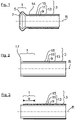
- a known pipe end 1 of a brake line 3 for a motor vehicle is shown.
- the pipe end 1 has a flanged head 5 which can be connected in a fluid-tight manner to a brake pressure transducer, for example, by means of a union nut (not shown).
- the flanging head 5 has a metallically pure, conical sealing surface 7 on the front side, which is smooth all around, free of cracks and grooves.
- the tube end 1 is designed to be rotationally symmetrical about the tube axis R.
- the brake line 3 and thus also the tube end 1 is constructed in several layers, namely with a radially inner steel tube 9, on which an aluminum or zinc layer 11 is applied for corrosion protection.
- the steel pipe 9 and the zinc layer 11 form a metallic pipe core 13 which is encased on the outside with a plastic coating 15, in particular a PA layer.
- a brake line 3 is provided with a pipe end 1 that has not yet been machined.
- a chamfering tool (not shown)
- the free end face of the pipe end 1 is machined flat and the end face outer edge 17 of the pipe end 1 is also chamfered.
- the resulting material removal during the chamfering process is in the 2 indicated with dotted lines.
- the method step illustrated in the method step involves stripping or stripping the pipe end 1, in which the plastic coating 15 is removed from the pipe end 1 over a predetermined stripping length e, exposing the zinc layer 11.
- the resulting material removal is in the 3 also indicated with dashed lines.
- the invention relates in particular to the 2 indicated step for stripping the pipe end 1.
- the tool shown is provided, the structure and mode of operation of which is described below:
- the tool 19 has a drive spindle 21 which merges into an approximately disk-shaped carrier 23 .
- a total of four roller elements 25 (or cutting bushes) are rotatably mounted about an axis of rotation D on the carrier 23 .
- the axes of rotation D of the roller elements 25 are arranged eccentrically with respect to the drive spindle 21 .
- the four roller elements 25 are also mounted on the carrier 23 via carriages 27 so that they can be radially adjusted. How from the Figures 4 to 7 further shows that the four roller elements 25 with their roller surfaces 29 delimit a central receiving space 31, into which the pipe end 1 to be stripped (in one, in the 2 state shown) can retract over an intended stripping length e.
- the four roller elements 25 are spaced apart from one another in such a way that the pipe end 1 to be stripped is inserted into the receiving space 31 with a press fit. That is, the four roller elements 25 press with their roller surfaces 29 each with a contact pressure F A ( 7 ) against the outer circumference of the pipe end to be stripped 1.
- the tube axis R and the axes of rotation D are arranged axially parallel to one another, so that each of the roller elements 25 with its roller surfaces 29 is in continuous line contact with the plastic coating 15 to be detached over the entire intended stripping length e.
- the roller elements 25 each have a molded embossed edge 35 on their peripheral edges facing away from the carrier 23, which embossed edge 35 protrudes radially outwards from the roller surfaces 29 with a slight oversize ⁇ h.
- the embossed edges 35 of the roller elements 25 produce a circumferential predetermined breaking edge in the plastic coating 15.
- the stripping tool 19 After inserting the pipe end 1 into the receiving space 31, the stripping tool 19 is rotated. As a result, the roller elements 25 are rotated around the pipe end 1 in a rolling process. The roller elements 25 are each in rolling contact with the contact pressure F A with the plastic coating 15 to be detached. In this way, the plastic coating 15 is subjected to flexing in the area of the pipe end 1, during which the microstructure of the plastic coating 15 changes and makes it brittle. As a result, the plastic coating 15 can be detached from the tubular core 13 without leaving any residue and at the same time can be torn off from the predetermined breaking point formed by the embossed edges 35 . In this way, a process-reliable, sharp tear-off edge for the remaining plastic coating 15 is produced.
- the oversize ⁇ h of the cutting edges 35 is smaller than the material thickness s ( 7 ) of the plastic coating 15 to be removed.
Landscapes
- Engineering & Computer Science (AREA)
- General Engineering & Computer Science (AREA)
- Mechanical Engineering (AREA)
- Chemical & Material Sciences (AREA)
- Combustion & Propulsion (AREA)
- Physics & Mathematics (AREA)
- Optics & Photonics (AREA)
- Transportation (AREA)
- Turning (AREA)
Description
- Die Erfindung betrifft eine Vorrichtung zum Entmanteln eines Rohrendes einer mit einer Kunststoffbeschichtung beschichteten Brems- oder Kraftstoffleitung nach dem Oberbegriff des Patentanspruches 1 sowie ein Verfahren zum Entmanteln des Rohrendes nach dem Patentanspruch 10.
- Eine Brems- oder Kraftstoffleitung kann mehrschichtig aufgebaut sein, und zwar mit einem inneren Aluminium- oder Stahlrohr, einer radial äußeren Aluminium- oder Zink-Schicht zum Korrosionsschutz sowie einer radial äußeren Kunststoffbeschichtung zum Schutz vor äußeren mechanischen Einflüssen.
- Eine solche Bremsleitung weist an ihrem Rohrende in gängiger Praxis einen Bördelkopf auf, der mittels einer Überwurfmutter mit einem Bremsdruckgeber verbind bar ist. An die Dichtfläche des Bördelkopfes sind besondere Anforderungen zu stellen. So muss die Dichtfläche metallisch rein sowie umlaufend glatt, rissfrei und frei von Riefen sein, um eine einwandfreie Abdichtung mit dem Druckgeber zu gewährleisten. Problematisch ist speziell die Vorbereitung für die Durchführung einer einwandfreien Bördelung des Rohrendes, bei der die Kunststoffbeschichtung rückstandfrei vom Rohrende zu entfernen ist. Gegebenenfalls nicht vom Rohrende entfernte Kunststoffpartikel können nämlich eine erhebliche Gefahr für die Funktionssicherheit des Bremssystems darstellen, sofern solche Kunststoffpartikel bei Montagevorgängen in den hydraulischen Bremskreislauf gelangen.
- Aus der
DE 202 14 365 U1 ist eine Vorrichtung zum Entmanteln eines Rohrendes einer Bremsleitung bekannt. Die Vorrichtung weist ein Schälwerkzeug auf, deren Schneiden die Kunststoffbeschichtung im Bereich des Rohrendes abschälen, ohne den metallischen Rohrkern der Bremsleitung zu beschädigen. - Bei Verwendung des Schälwerkzeugs besteht ein Risiko darin, dass aufgrund von relativ großen Fertigungstoleranzen der Bremsleitung unbeabsichtigt auch die Zink-Schicht abgeschält wird, wodurch der Korrosionsschutz nicht mehr gewährleistet ist. Aus der
DE 295 10 705 U1 ist eine alternative Vorrichtung zur Entfernung der Kunststoffbeschichtung vom Rohrende einer Brems- oder Kraftstoffleitung bekannt, bei der die Kunststoffbeschichtung nicht mit einem Schälwerkzeug, sondern durch Laserbehandlung abgetragen wird. Die Bereitstellung einer solchen Laserbehandlung ist jedoch bauteilaufwändig und daher entsprechend kostenintensiv. - Die Aufgabe der Erfindung besteht darin, eine Vorrichtung sowie ein Verfahren bereitzustellen, die ein prozesssicheres Entmanteln des Rohrendes der mit einer Kunststoffbeschichtung beschichteten Brems- oder Kraftstoffleitung ermöglicht.
- Die Aufgabe der Erfindung ist durch die Merkmale des Patentanspruches 1 oder des Patentanspruches 10 gelöst. Bevorzugte Weiterbildungen der Erfindung sind in den Unteransprüchen offenbart.
- Die Erfindung beruht auf der Problematik, dass bei dem, aus dem Stand der Technik bekannten Abschälen der Kunststoffbeschichtung die Gefahr einer Beschädigung des radial inneren metallischen Rohrkerns durch das Schälwerkzeug besteht. Vor diesem Hintergrund weist die erfindungsgemäße Vorrichtung nach dem Kennzeichnungsteil des Patentanspruches 1 kein Schälwerkzeug, sondern zumindest ein Druckelement auf, mit dem die Kunststoffbeschichtung durch eine mechanische Walkbearbeitung vom Rohrkern ablösbar ist. Bei der Walkbearbeitung ist die Kunststoffbeschichtung wechselweise einer Druckbelastung und einer Druckentlastung unterworfen.
- In einer bevorzugten technischen Realisierung kann das Druckelement ein Rollenelement sein, das mit einer Anpresskraft in Rollkontakt mit dem, zu entmantelnden Rohrende bringbar ist. Zur Entfernung der Kunststoffbeschichtung wird ein Abrollvorgang durchgeführt, bei dem sich infolge Walkarbeit die Kunststoffbeschichtung vom metallischen Rohrkern ablöst. Im Unterschied zum Stand der Technik wird also die Kunststoffbeschichtung weder durch Abschälen noch durch Laserbearbeitung abgetragen. Vielmehr wird die abzutragende Kunststoffbeschichtung einer Walkarbeit unterworfen, bei der die Kunststoffbeschichtung unter Änderung der Gefügestruktur versprödet und sich dadurch prozesssicher von dem metallischen Rohrkern ablösen lässt. Mit der Walkbearbeitung findet - im Vergleich zu den bereits bekannten Ablöseverfahren - ein neues physikalisches Wirkprinzip Anwendung.
- Zur Realisierung des Abrollvorganges ist es bevorzugt, wenn das Rollenelement um eine Drehachse rotierbar ist, die achsparallel zur Längsachse des Rohrendes positioniert ist. Dabei kann das Rollenelement mit seiner Rollfläche über eine vorgegebene Entmantelungslänge durchgängig in Linienkontakt mit dem zu entmantelnden Rohrende gebracht sein.
- Für ein prozesssicheres Ablösen der Kunststoffbeschichtung vom Rohrkern kann die Vorrichtung ein Schneid- oder Prägeelement aufweisen, mit der eine Sollbruchkante in der Kunststoffbeschichtung festlegbar ist. An der Sollbruchkante kann die, durch die Walkbearbeitung versprödete Kunststoffbeschichtung ohne weiteres abreißen, wodurch ein sauberer prozesssicherer Übergang des freigelegten Rohrendes zur verbleibenden Kunststoffbeschichtung gewährleistet ist.
- Besonders bevorzugt ist es, wenn das Schneid- oder Prägeelement eine am Rollenelement angeformte Prägekante ist. Die Prägekante kann mit einem vorgegebenen Übermaß die Rollfläche des Rollenelementes überragen. Das Übermaß der Prägekante ist bevorzugt so bemessen, dass es kleiner als die Materialstärke der abzutragenden Kunststoffbeschichtung ist. Die Kunststoffbeschichtung weist in gängiger Praxis eine Materialstärke im Bereich von ca. 0,25 mm auf. Das verwendete Kunststoffmaterial ist üblicherweise ein Polyamid.
- Zur Durchführung des Abrollvorgangs kann das Rollenelement an einem Träger drehgelagert sein. Der Träger kann wiederum über eine Antriebsspindel angetrieben werden, und zwar so, dass sich die Rollenelement-Drehachse mit vorgegebener Drehzahl um die zentrisch ausgerichtete Längsachse des Rohrendes dreht.
- Besonders bevorzugt ist es, wenn nicht nur ein, sondern eine Anzahl von Rollenelementen vorgesehen ist, beispielsweise drei oder vier Rollenelemente, die gleichmäßig umfangsverteilt um das Rohrende herum angeordnet sind. Die Rollenelemente begrenzen mit ihren einander zugewandten Rollenflächen einen zentrischen Aufnahmeraum, in den das zu entmantelnden Rohrende mit einer vorgegebenen Entmantelungslänge einsteckbar ist. Der Einsteckvorgang erfolgt bevorzugt unter Presspassung, bei der die Rollenelemente mit der bereits oben erwähnten Anpresskraft gegen das Rohrende drücken. Anschließend wird der Rollenelement-Träger in Rotation versetzt, wodurch die Rollenelemente am noch kunststoffbeschichteten Rohrende der Brems- oder Kraftstoffleitung abrollen.
- Die Vorrichtung kann bevorzugt ein Anfaswerkzeug aufweisen, mit dem die stirnseitige Außenkante des Rohrendes noch vor der Entmantelung angefast werden kann. Auf diese Weise wird das Einfädeln des Rohrendes in den oben erwähnten, zentrischen Aufnahmeraum vereinfacht.
- Zur weiteren Reinigung kann anschließend nach erfolgter Entmantelung der freigelegte metallische Rohrkern mit einem Bürstwerkzeug abgebürstet werden.
- Die vorstehend erläuterten und/oder in den Unteransprüchen wiedergegebenen vorteilhaften Aus- und/oder Weiterbildungen der Erfindung können - außer zum Beispiel in den Fällen eindeutiger Abhängigkeiten oder unvereinbarer Alternativen - einzeln oder aber auch in beliebiger Kombination miteinander zur Anwendung kommen.
- Die Erfindung und ihre vorteilhaften Aus- und Weiterbildungen sowie deren Vorteile werden nachfolgend anhand von Zeichnungen näher erläutert.
- Es zeigen:
- Fig. 1
- in einer Seitenschnittdarstellung ein bereits fertig bearbeitetes Rohrende einer Bremsleitung mit einem Bördelkopf;
- Fig. 2 und 3
- jeweils das Rohrende der Bremsleitung in unterschiedlichen Bearbeitungszuständen; sowie
- Fig. 4 bis 7
- jeweils unterschiedliche Ansichten eines Werkzeugs zur Entschichtung bzw. zum Entmanteln des Rohrendes.
- In der
Fig. 1 ist ein an sich bekanntes Rohrende 1 einer Bremsleitung 3 für ein Kraftfahrzeug gezeigt. Das Rohrende 1 weist einen Bördelkopf 5 auf, der mittels einer nicht dargestellten Überwurfmutter mit zum Beispiel einem Bremsdruckgeber fluiddicht verbindbar ist. Für eine solche fluiddichte Verbindung weist der Bördelkopf 5 stirnseitig eine metallisch reine, konisch ausgebildete Dichtfläche 7 auf, die umlaufend glatt, rissfrei sowie frei von Riefen ist. Das Rohrende 1 ist in gängiger Praxis rotationssymmetrisch um die Rohrachse R ausgebildet. - Wie aus der
Fig. 1 weiter hervorgeht, ist die Bremsleitung 3 und damit auch das Rohrende 1 mehrschichtig aufgebaut, und zwar mit einem radial inneren Stahlrohr 9, auf dem eine Aluminium- oder Zink-Schicht 11 für einen Korrosionsschutz aufgetragen ist. Das Stahlrohr 9 und die Zink-Schicht 11 bilden einen metallischen Rohrkern 13, der außenseitig mit einer Kunststoffbeschichtung 15, insbesondere einer PA-Schicht, ummantelt ist. - Nachfolgend werden anhand der
Fig. 2 bis 7 die Verfahrensschritte zur Herstellung der in derFig. 1 gezeigten Bördelkopf-Geometrie der Bremsleitung 3 beschrieben: So wird zunächst gemäß derFig. 2 eine Bremsleitung 3 mit einem noch unbearbeiteten Rohrende 1 bereitgestellt. Mit Hilfe eines nicht gezeigten Anfaswerkzeugs wird die freie Stirnseite des Rohrendes 1 ebenflächig bearbeitet und zudem auch die stirnseitige Außenkante 17 des Rohrendes 1 angefast. Der sich beim Anfasvorgang ergebende Materialabtrag ist in derFig. 2 mit gestichelten Linien angedeutet. - In einem anschließenden, in der
Fig. 3 veranschaulichten Verfahrensschritt erfolgt ein Entmanteln bzw. ein Entschichten des Rohrendes 1, bei dem über eine vorgegebene Entmantelungslänge e die Kunststoffbeschichtung 15 vom Rohrende 1 abgetragen wird, und zwar unter Freilegung der Zink-Schicht 11. Der hierdurch entstehende Materialabtrag ist in derFig. 3 ebenfalls mit gestrichelten Linien angedeutet. - Anschließend erfolgt mit Hilfe eines nicht dargestellten Bördel-Werkzeuges eine Bördelung des Rohrendes 1, wodurch der in der
Fig. 1 dargestellte Bördelkopf 5 erzeugt wird. - Die Erfindung betrifft insbesondere den in der
Fig. 2 angedeuteten Verfahrensschritt zum Entmanteln des Rohrendes 1. Hierzu ist das in denFig. 4 bis 7 gezeigte Werkzeug vorgesehen, dessen Aufbau und Funktionsweise nachfolgend beschrieben ist: So weist das Werkzeug 19 eine Antriebsspindel 21 auf, die in einen in etwa scheibenförmigen Träger 23 übergeht. Am Träger 23 sind insgesamt vier Rollenelemente 25 (bzw. Schneidbuchsen) drehbar um eine Drehachse D drehbar gelagert. Die Drehachsen D der Rollenelemente 25 sind mit Bezug auf die Antriebsspindel 21 außermittig angeordnet. - Die vier Rollenelemente 25 sind zudem radial verstellbar über Schlitten 27 an dem Träger 23 montiert. Wie aus den
Fig. 4 bis 7 weiter hervorgeht, begrenzen die vier Rollenelemente 25 mit ihren Rollenflächen 29 einen zentrischen Aufnahmeraum 31, in den das zu entmantelnde Rohrende 1 (in einem, in derFig. 2 gezeigten Zustand) über eine beabsichtigte Entmantelungslänge e einfahren kann. Die vier Rollenelemente 25 sind so voneinander beabstandet, dass das zu entmantelnde Rohrende 1 unter Presspassung in den Aufnahmeraum 31 eingesteckt wird. Das heißt, die vier Rollenelemente 25 drücken mit ihren Rollenflächen 29 jeweils mit einer Anpresskraft FA (Fig. 7 ) gegen den Außenumfang des zu entmantelnden Rohrendes 1. - Die Rohrachse R sowie die Drehachsen D sind achsparallel zueinander angeordnet, so dass jedes der Rollenelemente 25 mit seinen Rollenflächen 29 jeweils über die gesamte beabsichtigte Entmantelungslänge e in einem durchgängigen Linienkontakt mit der abzulösenden Kunststoffbeschichtung 15 ist.
- Wie speziell in der
Fig. 7 gezeigt ist, weisen die Rollenelemente 25 an ihren, vom Träger 23 abgewandten Umfangskanten jeweils eine angeformte Prägekante 35 auf, die mit einem geringfügigen Übermaß Δh radial nach außen von den Rollenflächen 29 abragen. Bei in den Aufnahmeraum 31 eingesetztem Rohrende 1 erzeugen die Prägekanten 35 der Rollenelemente 25 eine umlaufende Sollbruchkante in der Kunststoffbeschichtung 15. - Nach dem Einsetzen des Rohrendes 1 in den Aufnahmeraum 31 wird das Entmantelungs-Werkzeug 19 drehbetätigt. Dadurch werden die Rollenelemente 25 in einem Abrollvorgang um das Rohrende 1 gedreht. Die Rollenelemente 25 befinden sich jeweils mit der Anpresskraft FA in Rollkontakt mit der abzulösenden Kunststoffbeschichtung 15. Auf diese Weise wird die Kunststoffbeschichtung 15 im Bereich des Rohrendes 1 einer Walkbearbeitung unterworfen, bei der sich die Gefügestruktur der Kunststoffbeschichtung 15 ändert und diese versprödet. Dadurch kann sich die Kunststoffbeschichtung 15 rückstandfrei vom Rohrkern 13 ablösen und gleichzeitig auch von der durch die Prägekanten 35 gebildete Sollbruchstelle abreißen. Auf diese Weise ist eine prozesssichere scharfe Abrisskante zur noch verbleibenden Kunststoffbeschichtung 15 erzeugt. Das Übermaß Δh der Schneidkanten 35 ist kleiner als die Materialstärke s (
Fig. 7 ) der abzutragenden Kunststoffbeschichtung 15 bemessen.
Claims (10)
- Vorrichtung zum Entmanteln eines Rohrendes (1) einer mit einer Kunststoffbeschichtung (15) beschichteten Brems- oder Kraftstoffleitung (2), die einen metallischen Rohrkern (13) aufweist, dadurch gekennzeichnet, dass die Vorrichtung zumindest ein Druckelement (25) aufweist, mit dem die Kunststoffbeschichtung (15) durch eine mechanische Walkbearbeitung vom Rohrkern (13) ablösbar ist, bei der die Kunststoffbeschichtung (15) wechselweise einer Druckbelastung und einer Druckentlastung unterworfen ist, und dass die Druckbelastung und die Druckentlastung durch das Druckelement (25) derart bemessen ist, dass die Kunststoffbeschichtung (15) bei der Walkbearbeitung unter Änderung der Gefügestruktur versprödet.
- Vorrichtung nach Anspruch 1, dadurch gekennzeichnet, dass das Druckelement (25) ein drehbar gelagertes Rollenelement ist, das mit einer Anpresskraft (FA) in Rollkontakt mit dem zu entmantelnden Rohrende (1) bringbar ist, und dass die Walkbearbeitung durch einen Abrollvorgang des Rollenelements (25) auf dem zu entmantelnden Rohrende (1) erfolgt.
- Vorrichtung nach Anspruch 1 oder 2, dadurch gekennzeichnet, dass das Rollenelement (25) um eine Drehachse (D) rotierbar ist, die achsparallel zur Längsachse (R) des Rohrendes (1) positioniert ist, und/oder dass das Rollenelement (25) mit seiner Rollfläche (29) über eine vorgegebene Entmantelungslänge (e) durchgängig in Linienkontakt mit dem zu entmantelnden Rohrende (1) ist.
- Vorrichtung nach einem der vorhergehenden Ansprüche, dadurch gekennzeichnet, dass ein Schneidelement (35) vorgesehen ist, mit der eine Sollbruchkante (14) festlegbar ist, an der die Kunststoffbeschichtung (15) bei der Walkbearbeitung abreißt.
- Vorrichtung nach Anspruch 4, dadurch gekennzeichnet, dass das Schneidelement (35) eine am Rollenelement (25) angeformte Schneidkante ist, und dass insbesondere die Schneidkante mit einem vorgegebenen Übermaß (Δh) die Rollfläche (29) des Rollenelements (25) überragt, wobei insbesondere das Übermaß (Δh) der Schneidkante (35) kleiner als die Materialstärke (s) der abzutragenden Kunststoffbeschichtung (15) ist.
- Vorrichtung nach einem der vorhergehenden Ansprüche, dadurch gekennzeichnet, dass zur Durchführung des Abrollvorgangs die Drehachse (D) des Rollenelements (25) um die Längsachse (R) des Rohrendes (1) rotierbar gelagert ist.
- Vorrichtung nach einem der Ansprüche 2 bis 6, dadurch gekennzeichnet, dass eine Anzahl von Rollenelementen (25) vorgesehen ist, die insbesondere gleichmäßig umfangsverteilt um das Rohrende (1) angeordnet sind.
- Vorrichtung nach Anspruch 7, dadurch gekennzeichnet, dass die Rollenelemente (25) mit ihren Rollenflächen (29) einen Aufnahmeraum (31) begrenzen, in den das zu entmantelnde Rohrende (1) einsteckbar ist, und zwar insbesondere unter einer Presspassung, bei der die Rollenelemente (25) mit der Anpresskraft (FA) gegen das Rohrende (1) drücken.
- Vorrichtung nach Anspruch 8, dadurch gekennzeichnet, dass die Vorrichtung ein Anfaswerkzeug aufweist, mit dem vor dem Entmanteln die stirnseitige Außenkante (17) des Rohrendes (1) anfasbar ist, wodurch ein Einfädeln des Rohrendes (1) in den Aufnahmeraum (31) vereinfacht ist.
- Verfahren zum Entmanteln eines Rohrendes (1) einer mit einer Kunststoffbeschichtung (15) beschichteten Brems- oder Kraftstoffleitung (2), insbesondere mittels einer Vorrichtung nach einem der vorhergehenden Ansprüche, bei dem eine mechanische Walkbearbeitung der Kunststoffbeschichtung (15) erfolgt, bei der die Kunststoffbeschichtung (15) wechselweise einer Druckbelastung und einer Druckentlastung unterworfen wird und darauffolgend von dem Rohrkern (13) abgelöst wird, wobei die Druckbelastung und die Druckentlastung durch das Druckelement (25) derart bemessen ist, dass die Kunststoffbeschichtung (15) bei der Walkbearbeitung unter Änderung der Gefügestruktur versprödet.
Applications Claiming Priority (1)
| Application Number | Priority Date | Filing Date | Title |
|---|---|---|---|
| DE102013011213.3A DE102013011213B3 (de) | 2013-07-04 | 2013-07-04 | Vorrichtung zum Entmanteln eines Rohrendes einer mit einer Kunststoffbeschichtung beschichteten Brems- oder Kraftstoffleitung |
Publications (3)
| Publication Number | Publication Date |
|---|---|
| EP2837536A1 EP2837536A1 (de) | 2015-02-18 |
| EP2837536B1 EP2837536B1 (de) | 2016-11-30 |
| EP2837536B2 true EP2837536B2 (de) | 2022-04-06 |
Family
ID=51014168
Family Applications (1)
| Application Number | Title | Priority Date | Filing Date |
|---|---|---|---|
| EP14174058.9A Active EP2837536B2 (de) | 2013-07-04 | 2014-06-26 | Vorrichtung zum Entmanteln eines Rohrendes einer mit einer Kunststoffbeschichtung beschichteten Brems- oder Kraftstoffleitung |
Country Status (2)
| Country | Link |
|---|---|
| EP (1) | EP2837536B2 (de) |
| DE (1) | DE102013011213B3 (de) |
Families Citing this family (5)
| Publication number | Priority date | Publication date | Assignee | Title |
|---|---|---|---|---|
| DE102015105798B4 (de) | 2015-01-23 | 2016-12-08 | Cooper-Standard Automotive (Deutschland) Gmbh | Verfahren zum Herstellen einer Rohrleitung, insbesondere einer Bremsrohrleitung oder Kraftstoffrohrleitung für ein Kraftfahrzeug, sowie eine solche Rohrleitung |
| DE102016210887A1 (de) | 2016-06-17 | 2017-12-21 | Cooper-Standard Automotive (Deutschland) Gmbh | Verfahren zum Herstellen einer Rohrleitung, insbesondere Bremsrohrleitung oder Kraftstoffrohrleitung für ein Kraftfahrzeug, sowie eine solche Rohrleitung |
| TWI598191B (zh) | 2016-09-12 | 2017-09-11 | Tai-Hung Lee | Part of the outer metal scraper hand tool with a non-metallic outer composite metal tube |
| DE102019135827A1 (de) * | 2019-12-27 | 2021-07-01 | Cooper-Standard Automotive (Deutschland) Gmbh | Überwurfschraube für mit wenigstens einem Bördel versehene Rohrleitungen, insbesondere Bremsrohre |
| WO2026006223A1 (en) * | 2024-06-24 | 2026-01-02 | Cummins Inc. | Leak tight connection in a high-pressure hydrogen pipeline |
Citations (6)
| Publication number | Priority date | Publication date | Assignee | Title |
|---|---|---|---|---|
| US3965570A (en) † | 1975-04-21 | 1976-06-29 | The Weatherhead Company | Hose skiving tool |
| WO1985002816A1 (en) † | 1983-12-23 | 1985-07-04 | Ellett William A | Method and apparatus for removing protective coating from pipe section |
| DE29510705U1 (de) † | 1995-07-01 | 1995-10-19 | Jet Laser Systeme Gesellschaft für Oberflächentechnik mbH, 41836 Hückelhoven | Vorrichtung zum Entfernen einer Beschichtung von einem im wesentlichen rotationssymmetrischen Werkstück mittels Laserstrahlung |
| DE20214365U1 (de) † | 2002-09-16 | 2002-11-21 | Klann Tools Ltd., Oxfordshire | Vorrichtung zum Entmanteln einer Bremsleitung |
| DE10140925A1 (de) † | 2001-08-15 | 2003-03-13 | Itt Mfg Enterprises Inc | Vorrichtung zum Entschichten von Rohren |
| DE102008043876A1 (de) † | 2008-11-19 | 2010-05-20 | Robert Bosch Gmbh | Verfahren und Vorrichtung zum Abisolieren eines isolierten Drahtes |
-
2013
- 2013-07-04 DE DE102013011213.3A patent/DE102013011213B3/de active Active
-
2014
- 2014-06-26 EP EP14174058.9A patent/EP2837536B2/de active Active
Patent Citations (6)
| Publication number | Priority date | Publication date | Assignee | Title |
|---|---|---|---|---|
| US3965570A (en) † | 1975-04-21 | 1976-06-29 | The Weatherhead Company | Hose skiving tool |
| WO1985002816A1 (en) † | 1983-12-23 | 1985-07-04 | Ellett William A | Method and apparatus for removing protective coating from pipe section |
| DE29510705U1 (de) † | 1995-07-01 | 1995-10-19 | Jet Laser Systeme Gesellschaft für Oberflächentechnik mbH, 41836 Hückelhoven | Vorrichtung zum Entfernen einer Beschichtung von einem im wesentlichen rotationssymmetrischen Werkstück mittels Laserstrahlung |
| DE10140925A1 (de) † | 2001-08-15 | 2003-03-13 | Itt Mfg Enterprises Inc | Vorrichtung zum Entschichten von Rohren |
| DE20214365U1 (de) † | 2002-09-16 | 2002-11-21 | Klann Tools Ltd., Oxfordshire | Vorrichtung zum Entmanteln einer Bremsleitung |
| DE102008043876A1 (de) † | 2008-11-19 | 2010-05-20 | Robert Bosch Gmbh | Verfahren und Vorrichtung zum Abisolieren eines isolierten Drahtes |
Also Published As
| Publication number | Publication date |
|---|---|
| DE102013011213B3 (de) | 2014-10-30 |
| EP2837536A1 (de) | 2015-02-18 |
| EP2837536B1 (de) | 2016-11-30 |
Similar Documents
| Publication | Publication Date | Title |
|---|---|---|
| EP2837536B2 (de) | Vorrichtung zum Entmanteln eines Rohrendes einer mit einer Kunststoffbeschichtung beschichteten Brems- oder Kraftstoffleitung | |
| DE102008024313A1 (de) | Verfahren zur Vorkonditionierung einer zu beschichtenden Oberfläche | |
| EP2289659A1 (de) | Vorrichtung zum Reibschweissverbinden von mindestens zwei Platten durch ein Verbindungselement mit einer Einrichtung zum Messen der ausgeübten Kraft und der Vorschublänge während des Verbindens | |
| EP2659158B1 (de) | Bremsscheibe und verfahren zur behandlung der oberfläche einer bremsscheibe | |
| DE102013000574A1 (de) | Rührreibschweißvorrichtung | |
| DE68922370T2 (de) | Vorrichtung zum Anbringen von Hüllen auf elektrische Kabelverbindungen. | |
| DE102005004754A1 (de) | Verfahren zur Nachreinigung von abisolierten Bereichen einer elektrischen Leitung | |
| EP2514589A1 (de) | Verfahren zur Herstellung einer bereichsweise beschichteten Trägerstruktur | |
| EP2167254A2 (de) | Verfahren zur herstellung einer nabe im drückverfahren mittels wenigstens einer drehbaren drückrolle | |
| WO2010048931A1 (de) | Vorrichtung zum partiellen abdecken einer bauteilzone | |
| DE102019121563A1 (de) | Verfahren zur Herstellung eines Bauteils sowie Bauteil hierzu | |
| DE102019213464A1 (de) | Verfahren zum Herstellen eines Reibbremskörpers für eine Reibbremse eines Kraftfahrzeugs | |
| EP3470186B1 (de) | Verfahren und vorrichtung zum abisolieren von vorisolierten rohrleitungen | |
| DE102011078591A1 (de) | Verfahren zum Herstellen eines bereichsweise mit einer Beschichtung versehenen Substrats | |
| WO2008154940A1 (de) | Verfahren zur reparatur eines bereichs einer wärmedämmschicht | |
| EP1656235B1 (de) | Verfahren zur herstellung von bauteilen | |
| DE19820498A1 (de) | Verfahren zum Herstellen einer Hülse, insbesondere für die Druckindustrie | |
| DE102011005644A1 (de) | Verfahren zur Herstellung einer Funktionsoberfläche auf einem metallischen Bauteil | |
| EP3550684B1 (de) | Abisolieren von elektrischen leitungen mittels ultraschalls | |
| EP2045092A2 (de) | Gummisleeve | |
| DE102014202066A1 (de) | Bohrvorrichtung und Verfahren zum Einbringen einer Bohrung | |
| DE102024104592A1 (de) | Verfahren zum Bearbeiten von Drähten zur Herstellung eines Drahtkorbs sowie Drahtkorb, insbesondere Wasch- oder Spülkorb, oder Teil davon | |
| DE2320211B2 (de) | Fertigbauteil fuer einen schacht, insbesondere muellabwurfschacht, aus einem mehrschichtigen flachmaterial sowie verfahren zur herstellung des fertigbauteils und von zuschnitten hierfuer | |
| EP1103317A2 (de) | Verfahren und Vorrichtung zum Lochen von Blechformteilen aus einem Aluminiumwerkstoff | |
| DE102013209614A1 (de) | Verfahren zur Herstellung eines strukturierten Bauteils |
Legal Events
| Date | Code | Title | Description |
|---|---|---|---|
| 17P | Request for examination filed |
Effective date: 20140626 |
|
| AK | Designated contracting states |
Kind code of ref document: A1 Designated state(s): AL AT BE BG CH CY CZ DE DK EE ES FI FR GB GR HR HU IE IS IT LI LT LU LV MC MK MT NL NO PL PT RO RS SE SI SK SM TR |
|
| AX | Request for extension of the european patent |
Extension state: BA ME |
|
| PUAI | Public reference made under article 153(3) epc to a published international application that has entered the european phase |
Free format text: ORIGINAL CODE: 0009012 |
|
| R17P | Request for examination filed (corrected) |
Effective date: 20150818 |
|
| RBV | Designated contracting states (corrected) |
Designated state(s): AL AT BE BG CH CY CZ DE DK EE ES FI FR GB GR HR HU IE IS IT LI LT LU LV MC MK MT NL NO PL PT RO RS SE SI SK SM TR |
|
| GRAP | Despatch of communication of intention to grant a patent |
Free format text: ORIGINAL CODE: EPIDOSNIGR1 |
|
| RIC1 | Information provided on ipc code assigned before grant |
Ipc: B60T 17/04 20060101AFI20160629BHEP Ipc: B23D 79/12 20060101ALI20160629BHEP |
|
| INTG | Intention to grant announced |
Effective date: 20160721 |
|
| GRAS | Grant fee paid |
Free format text: ORIGINAL CODE: EPIDOSNIGR3 |
|
| GRAA | (expected) grant |
Free format text: ORIGINAL CODE: 0009210 |
|
| AK | Designated contracting states |
Kind code of ref document: B1 Designated state(s): AL AT BE BG CH CY CZ DE DK EE ES FI FR GB GR HR HU IE IS IT LI LT LU LV MC MK MT NL NO PL PT RO RS SE SI SK SM TR |
|
| REG | Reference to a national code |
Ref country code: CH Ref legal event code: EP Ref country code: GB Ref legal event code: FG4D Free format text: NOT ENGLISH |
|
| REG | Reference to a national code |
Ref country code: AT Ref legal event code: REF Ref document number: 849488 Country of ref document: AT Kind code of ref document: T Effective date: 20161215 |
|
| REG | Reference to a national code |
Ref country code: IE Ref legal event code: FG4D Free format text: LANGUAGE OF EP DOCUMENT: GERMAN |
|
| REG | Reference to a national code |
Ref country code: DE Ref legal event code: R096 Ref document number: 502014002071 Country of ref document: DE |
|
| PG25 | Lapsed in a contracting state [announced via postgrant information from national office to epo] |
Ref country code: LV Free format text: LAPSE BECAUSE OF FAILURE TO SUBMIT A TRANSLATION OF THE DESCRIPTION OR TO PAY THE FEE WITHIN THE PRESCRIBED TIME-LIMIT Effective date: 20161130 |
|
| REG | Reference to a national code |
Ref country code: LT Ref legal event code: MG4D |
|
| REG | Reference to a national code |
Ref country code: NL Ref legal event code: MP Effective date: 20161130 |
|
| PG25 | Lapsed in a contracting state [announced via postgrant information from national office to epo] |
Ref country code: NO Free format text: LAPSE BECAUSE OF FAILURE TO SUBMIT A TRANSLATION OF THE DESCRIPTION OR TO PAY THE FEE WITHIN THE PRESCRIBED TIME-LIMIT Effective date: 20170228 Ref country code: GR Free format text: LAPSE BECAUSE OF FAILURE TO SUBMIT A TRANSLATION OF THE DESCRIPTION OR TO PAY THE FEE WITHIN THE PRESCRIBED TIME-LIMIT Effective date: 20170301 Ref country code: SE Free format text: LAPSE BECAUSE OF FAILURE TO SUBMIT A TRANSLATION OF THE DESCRIPTION OR TO PAY THE FEE WITHIN THE PRESCRIBED TIME-LIMIT Effective date: 20161130 Ref country code: LT Free format text: LAPSE BECAUSE OF FAILURE TO SUBMIT A TRANSLATION OF THE DESCRIPTION OR TO PAY THE FEE WITHIN THE PRESCRIBED TIME-LIMIT Effective date: 20161130 |
|
| PG25 | Lapsed in a contracting state [announced via postgrant information from national office to epo] |
Ref country code: HR Free format text: LAPSE BECAUSE OF FAILURE TO SUBMIT A TRANSLATION OF THE DESCRIPTION OR TO PAY THE FEE WITHIN THE PRESCRIBED TIME-LIMIT Effective date: 20161130 Ref country code: FI Free format text: LAPSE BECAUSE OF FAILURE TO SUBMIT A TRANSLATION OF THE DESCRIPTION OR TO PAY THE FEE WITHIN THE PRESCRIBED TIME-LIMIT Effective date: 20161130 Ref country code: ES Free format text: LAPSE BECAUSE OF FAILURE TO SUBMIT A TRANSLATION OF THE DESCRIPTION OR TO PAY THE FEE WITHIN THE PRESCRIBED TIME-LIMIT Effective date: 20161130 Ref country code: RS Free format text: LAPSE BECAUSE OF FAILURE TO SUBMIT A TRANSLATION OF THE DESCRIPTION OR TO PAY THE FEE WITHIN THE PRESCRIBED TIME-LIMIT Effective date: 20161130 Ref country code: PT Free format text: LAPSE BECAUSE OF FAILURE TO SUBMIT A TRANSLATION OF THE DESCRIPTION OR TO PAY THE FEE WITHIN THE PRESCRIBED TIME-LIMIT Effective date: 20170330 Ref country code: PL Free format text: LAPSE BECAUSE OF FAILURE TO SUBMIT A TRANSLATION OF THE DESCRIPTION OR TO PAY THE FEE WITHIN THE PRESCRIBED TIME-LIMIT Effective date: 20161130 |
|
| REG | Reference to a national code |
Ref country code: FR Ref legal event code: PLFP Year of fee payment: 4 |
|
| PG25 | Lapsed in a contracting state [announced via postgrant information from national office to epo] |
Ref country code: NL Free format text: LAPSE BECAUSE OF FAILURE TO SUBMIT A TRANSLATION OF THE DESCRIPTION OR TO PAY THE FEE WITHIN THE PRESCRIBED TIME-LIMIT Effective date: 20161130 |
|
| PG25 | Lapsed in a contracting state [announced via postgrant information from national office to epo] |
Ref country code: DK Free format text: LAPSE BECAUSE OF FAILURE TO SUBMIT A TRANSLATION OF THE DESCRIPTION OR TO PAY THE FEE WITHIN THE PRESCRIBED TIME-LIMIT Effective date: 20161130 Ref country code: EE Free format text: LAPSE BECAUSE OF FAILURE TO SUBMIT A TRANSLATION OF THE DESCRIPTION OR TO PAY THE FEE WITHIN THE PRESCRIBED TIME-LIMIT Effective date: 20161130 Ref country code: SK Free format text: LAPSE BECAUSE OF FAILURE TO SUBMIT A TRANSLATION OF THE DESCRIPTION OR TO PAY THE FEE WITHIN THE PRESCRIBED TIME-LIMIT Effective date: 20161130 Ref country code: RO Free format text: LAPSE BECAUSE OF FAILURE TO SUBMIT A TRANSLATION OF THE DESCRIPTION OR TO PAY THE FEE WITHIN THE PRESCRIBED TIME-LIMIT Effective date: 20161130 Ref country code: CZ Free format text: LAPSE BECAUSE OF FAILURE TO SUBMIT A TRANSLATION OF THE DESCRIPTION OR TO PAY THE FEE WITHIN THE PRESCRIBED TIME-LIMIT Effective date: 20161130 |
|
| REG | Reference to a national code |
Ref country code: DE Ref legal event code: R026 Ref document number: 502014002071 Country of ref document: DE |
|
| PLBI | Opposition filed |
Free format text: ORIGINAL CODE: 0009260 |
|
| PG25 | Lapsed in a contracting state [announced via postgrant information from national office to epo] |
Ref country code: SM Free format text: LAPSE BECAUSE OF FAILURE TO SUBMIT A TRANSLATION OF THE DESCRIPTION OR TO PAY THE FEE WITHIN THE PRESCRIBED TIME-LIMIT Effective date: 20161130 Ref country code: BG Free format text: LAPSE BECAUSE OF FAILURE TO SUBMIT A TRANSLATION OF THE DESCRIPTION OR TO PAY THE FEE WITHIN THE PRESCRIBED TIME-LIMIT Effective date: 20170228 Ref country code: IT Free format text: LAPSE BECAUSE OF FAILURE TO SUBMIT A TRANSLATION OF THE DESCRIPTION OR TO PAY THE FEE WITHIN THE PRESCRIBED TIME-LIMIT Effective date: 20161130 |
|
| 26 | Opposition filed |
Opponent name: COOPER-STANDARD AUTOMOTIVE (DEUTSCHLAND) GMBH Effective date: 20170821 |
|
| PLAX | Notice of opposition and request to file observation + time limit sent |
Free format text: ORIGINAL CODE: EPIDOSNOBS2 |
|
| PG25 | Lapsed in a contracting state [announced via postgrant information from national office to epo] |
Ref country code: SI Free format text: LAPSE BECAUSE OF FAILURE TO SUBMIT A TRANSLATION OF THE DESCRIPTION OR TO PAY THE FEE WITHIN THE PRESCRIBED TIME-LIMIT Effective date: 20161130 |
|
| PG25 | Lapsed in a contracting state [announced via postgrant information from national office to epo] |
Ref country code: MC Free format text: LAPSE BECAUSE OF FAILURE TO SUBMIT A TRANSLATION OF THE DESCRIPTION OR TO PAY THE FEE WITHIN THE PRESCRIBED TIME-LIMIT Effective date: 20161130 |
|
| REG | Reference to a national code |
Ref country code: CH Ref legal event code: PL |
|
| PLBB | Reply of patent proprietor to notice(s) of opposition received |
Free format text: ORIGINAL CODE: EPIDOSNOBS3 |
|
| REG | Reference to a national code |
Ref country code: IE Ref legal event code: MM4A |
|
| PG25 | Lapsed in a contracting state [announced via postgrant information from national office to epo] |
Ref country code: IE Free format text: LAPSE BECAUSE OF NON-PAYMENT OF DUE FEES Effective date: 20170626 Ref country code: CH Free format text: LAPSE BECAUSE OF NON-PAYMENT OF DUE FEES Effective date: 20170630 Ref country code: LI Free format text: LAPSE BECAUSE OF NON-PAYMENT OF DUE FEES Effective date: 20170630 Ref country code: LU Free format text: LAPSE BECAUSE OF NON-PAYMENT OF DUE FEES Effective date: 20170626 |
|
| REG | Reference to a national code |
Ref country code: BE Ref legal event code: MM Effective date: 20170630 |
|
| REG | Reference to a national code |
Ref country code: FR Ref legal event code: PLFP Year of fee payment: 5 |
|
| PG25 | Lapsed in a contracting state [announced via postgrant information from national office to epo] |
Ref country code: BE Free format text: LAPSE BECAUSE OF NON-PAYMENT OF DUE FEES Effective date: 20170630 |
|
| PG25 | Lapsed in a contracting state [announced via postgrant information from national office to epo] |
Ref country code: MT Free format text: LAPSE BECAUSE OF FAILURE TO SUBMIT A TRANSLATION OF THE DESCRIPTION OR TO PAY THE FEE WITHIN THE PRESCRIBED TIME-LIMIT Effective date: 20161130 |
|
| PLCK | Communication despatched that opposition was rejected |
Free format text: ORIGINAL CODE: EPIDOSNREJ1 |
|
| STAA | Information on the status of an ep patent application or granted ep patent |
Free format text: STATUS: THE PATENT HAS BEEN GRANTED |
|
| APBM | Appeal reference recorded |
Free format text: ORIGINAL CODE: EPIDOSNREFNO |
|
| APBP | Date of receipt of notice of appeal recorded |
Free format text: ORIGINAL CODE: EPIDOSNNOA2O |
|
| APAH | Appeal reference modified |
Free format text: ORIGINAL CODE: EPIDOSCREFNO |
|
| PG25 | Lapsed in a contracting state [announced via postgrant information from national office to epo] |
Ref country code: HU Free format text: LAPSE BECAUSE OF FAILURE TO SUBMIT A TRANSLATION OF THE DESCRIPTION OR TO PAY THE FEE WITHIN THE PRESCRIBED TIME-LIMIT; INVALID AB INITIO Effective date: 20140626 |
|
| APBQ | Date of receipt of statement of grounds of appeal recorded |
Free format text: ORIGINAL CODE: EPIDOSNNOA3O |
|
| PG25 | Lapsed in a contracting state [announced via postgrant information from national office to epo] |
Ref country code: CY Free format text: LAPSE BECAUSE OF FAILURE TO SUBMIT A TRANSLATION OF THE DESCRIPTION OR TO PAY THE FEE WITHIN THE PRESCRIBED TIME-LIMIT Effective date: 20161130 |
|
| PG25 | Lapsed in a contracting state [announced via postgrant information from national office to epo] |
Ref country code: MK Free format text: LAPSE BECAUSE OF FAILURE TO SUBMIT A TRANSLATION OF THE DESCRIPTION OR TO PAY THE FEE WITHIN THE PRESCRIBED TIME-LIMIT Effective date: 20161130 |
|
| PG25 | Lapsed in a contracting state [announced via postgrant information from national office to epo] |
Ref country code: TR Free format text: LAPSE BECAUSE OF FAILURE TO SUBMIT A TRANSLATION OF THE DESCRIPTION OR TO PAY THE FEE WITHIN THE PRESCRIBED TIME-LIMIT Effective date: 20161130 |
|
| PG25 | Lapsed in a contracting state [announced via postgrant information from national office to epo] |
Ref country code: AL Free format text: LAPSE BECAUSE OF FAILURE TO SUBMIT A TRANSLATION OF THE DESCRIPTION OR TO PAY THE FEE WITHIN THE PRESCRIBED TIME-LIMIT Effective date: 20161130 Ref country code: IS Free format text: LAPSE BECAUSE OF FAILURE TO SUBMIT A TRANSLATION OF THE DESCRIPTION OR TO PAY THE FEE WITHIN THE PRESCRIBED TIME-LIMIT Effective date: 20170330 |
|
| REG | Reference to a national code |
Ref country code: AT Ref legal event code: MM01 Ref document number: 849488 Country of ref document: AT Kind code of ref document: T Effective date: 20190626 |
|
| PG25 | Lapsed in a contracting state [announced via postgrant information from national office to epo] |
Ref country code: AT Free format text: LAPSE BECAUSE OF NON-PAYMENT OF DUE FEES Effective date: 20190626 |
|
| PLAB | Opposition data, opponent's data or that of the opponent's representative modified |
Free format text: ORIGINAL CODE: 0009299OPPO |
|
| R26 | Opposition filed (corrected) |
Opponent name: COOPER-STANDARD AUTOMOTIVE (DEUTSCHLAND) GMBH Effective date: 20170821 |
|
| APBU | Appeal procedure closed |
Free format text: ORIGINAL CODE: EPIDOSNNOA9O |
|
| PUAH | Patent maintained in amended form |
Free format text: ORIGINAL CODE: 0009272 |
|
| STAA | Information on the status of an ep patent application or granted ep patent |
Free format text: STATUS: PATENT MAINTAINED AS AMENDED |
|
| 27A | Patent maintained in amended form |
Effective date: 20220406 |
|
| AK | Designated contracting states |
Kind code of ref document: B2 Designated state(s): AL AT BE BG CH CY CZ DE DK EE ES FI FR GB GR HR HU IE IS IT LI LT LU LV MC MK MT NL NO PL PT RO RS SE SI SK SM TR |
|
| REG | Reference to a national code |
Ref country code: DE Ref legal event code: R102 Ref document number: 502014002071 Country of ref document: DE |
|
| P01 | Opt-out of the competence of the unified patent court (upc) registered |
Effective date: 20230530 |
|
| PGFP | Annual fee paid to national office [announced via postgrant information from national office to epo] |
Ref country code: DE Payment date: 20250630 Year of fee payment: 12 |
|
| PGFP | Annual fee paid to national office [announced via postgrant information from national office to epo] |
Ref country code: GB Payment date: 20250621 Year of fee payment: 12 |
|
| PGFP | Annual fee paid to national office [announced via postgrant information from national office to epo] |
Ref country code: FR Payment date: 20250617 Year of fee payment: 12 |