EP2837536B2 - Dispositif destiné à dénuder une extrémité de tuyau d'une conduite de frein ou de carburant revêtue d'une couche en matière synthétique - Google Patents
Dispositif destiné à dénuder une extrémité de tuyau d'une conduite de frein ou de carburant revêtue d'une couche en matière synthétique Download PDFInfo
- Publication number
- EP2837536B2 EP2837536B2 EP14174058.9A EP14174058A EP2837536B2 EP 2837536 B2 EP2837536 B2 EP 2837536B2 EP 14174058 A EP14174058 A EP 14174058A EP 2837536 B2 EP2837536 B2 EP 2837536B2
- Authority
- EP
- European Patent Office
- Prior art keywords
- pipe end
- plastic coating
- roller
- pressure
- coating
- Prior art date
- Legal status (The legal status is an assumption and is not a legal conclusion. Google has not performed a legal analysis and makes no representation as to the accuracy of the status listed.)
- Active
Links
Images


Classifications
-
- B—PERFORMING OPERATIONS; TRANSPORTING
- B23—MACHINE TOOLS; METAL-WORKING NOT OTHERWISE PROVIDED FOR
- B23D—PLANING; SLOTTING; SHEARING; BROACHING; SAWING; FILING; SCRAPING; LIKE OPERATIONS FOR WORKING METAL BY REMOVING MATERIAL, NOT OTHERWISE PROVIDED FOR
- B23D79/00—Methods, machines, or devices not covered elsewhere, for working metal by removal of material
- B23D79/12—Machines or devices for peeling bars or tubes making use of cutting bits arranged around the workpiece, otherwise than by turning
-
- B—PERFORMING OPERATIONS; TRANSPORTING
- B60—VEHICLES IN GENERAL
- B60T—VEHICLE BRAKE CONTROL SYSTEMS OR PARTS THEREOF; BRAKE CONTROL SYSTEMS OR PARTS THEREOF, IN GENERAL; ARRANGEMENT OF BRAKING ELEMENTS ON VEHICLES IN GENERAL; PORTABLE DEVICES FOR PREVENTING UNWANTED MOVEMENT OF VEHICLES; VEHICLE MODIFICATIONS TO FACILITATE COOLING OF BRAKES
- B60T17/00—Component parts, details, or accessories of power brake systems not covered by groups B60T8/00, B60T13/00 or B60T15/00, or presenting other characteristic features
- B60T17/04—Arrangements of piping, valves in the piping, e.g. cut-off valves, couplings or air hoses
-
- F—MECHANICAL ENGINEERING; LIGHTING; HEATING; WEAPONS; BLASTING
- F02—COMBUSTION ENGINES; HOT-GAS OR COMBUSTION-PRODUCT ENGINE PLANTS
- F02M—SUPPLYING COMBUSTION ENGINES IN GENERAL WITH COMBUSTIBLE MIXTURES OR CONSTITUENTS THEREOF
- F02M37/00—Apparatus or systems for feeding liquid fuel from storage containers to carburettors or fuel-injection apparatus; Arrangements for purifying liquid fuel specially adapted for, or arranged on, internal-combustion engines
- F02M37/0011—Constructional details; Manufacturing or assembly of elements of fuel systems; Materials therefor
- F02M37/0017—Constructional details; Manufacturing or assembly of elements of fuel systems; Materials therefor related to fuel pipes or their connections, e.g. joints or sealings
-
- F—MECHANICAL ENGINEERING; LIGHTING; HEATING; WEAPONS; BLASTING
- F16—ENGINEERING ELEMENTS AND UNITS; GENERAL MEASURES FOR PRODUCING AND MAINTAINING EFFECTIVE FUNCTIONING OF MACHINES OR INSTALLATIONS; THERMAL INSULATION IN GENERAL
- F16L—PIPES; JOINTS OR FITTINGS FOR PIPES; SUPPORTS FOR PIPES, CABLES OR PROTECTIVE TUBING; MEANS FOR THERMAL INSULATION IN GENERAL
- F16L19/00—Joints in which sealing surfaces are pressed together by means of a member, e.g. a swivel nut, screwed on, or into, one of the joint parts
- F16L19/02—Pipe ends provided with collars or flanges, integral with the pipe or not, pressed together by a screwed member
- F16L19/0243—Pipe ends provided with collars or flanges, integral with the pipe or not, pressed together by a screwed member specially adapted for use with coated pipes
-
- F—MECHANICAL ENGINEERING; LIGHTING; HEATING; WEAPONS; BLASTING
- F16—ENGINEERING ELEMENTS AND UNITS; GENERAL MEASURES FOR PRODUCING AND MAINTAINING EFFECTIVE FUNCTIONING OF MACHINES OR INSTALLATIONS; THERMAL INSULATION IN GENERAL
- F16L—PIPES; JOINTS OR FITTINGS FOR PIPES; SUPPORTS FOR PIPES, CABLES OR PROTECTIVE TUBING; MEANS FOR THERMAL INSULATION IN GENERAL
- F16L19/00—Joints in which sealing surfaces are pressed together by means of a member, e.g. a swivel nut, screwed on, or into, one of the joint parts
- F16L19/02—Pipe ends provided with collars or flanges, integral with the pipe or not, pressed together by a screwed member
- F16L19/025—Pipe ends provided with collars or flanges, integral with the pipe or not, pressed together by a screwed member the pipe ends having integral collars or flanges
- F16L19/028—Pipe ends provided with collars or flanges, integral with the pipe or not, pressed together by a screwed member the pipe ends having integral collars or flanges the collars or flanges being obtained by deformation of the pipe wall
Definitions
- the invention relates to a device for stripping a pipe end of a brake or fuel line coated with a plastic coating according to the preamble of patent claim 1 and a method for stripping the pipe end according to patent claim 10.
- a brake or fuel line can have a multilayer structure, with an inner aluminum or steel tube, a radially outer aluminum or zinc layer for corrosion protection, and a radially outer plastic coating to protect against external mechanical influences.
- Such a brake line has at its tube end in common practice on a flanged head, which can be connected to a brake pressure transducer by means of a union nut.
- a seal nut There are special requirements for the sealing surface of the flare head.
- the sealing surface must be metallically clean and smooth all around, free of cracks and grooves in order to ensure a perfect seal with the pressure transmitter.
- the preparation for carrying out a perfect flanging of the pipe end, in which the plastic coating is to be removed from the pipe end without leaving any residue, is particularly problematic. Plastic particles that may not have been removed from the end of the pipe can pose a significant risk to the functional reliability of the brake system if such plastic particles get into the hydraulic brake circuit during assembly processes.
- a device for stripping a tube end of a brake line is known.
- the device has a scraping tool whose cutting edges peel off the plastic coating in the area of the pipe end without damaging the metal pipe core of the brake line.
- the object of the invention is to provide a device and a method that enable process-reliable stripping of the tube end of the brake or fuel line coated with a plastic coating.
- the invention is based on the problem that when the plastic coating is peeled off, as is known from the prior art, there is a risk of the radially inner metal tube core being damaged by the peeling tool.
- the device according to the invention does not have a peeling tool, but rather at least one pressure element with which the plastic coating can be detached from the tube core by mechanical milling. During fulling, the plastic coating is alternately subjected to pressure loading and pressure relief.
- the pressure element can be a roller element that can be brought into rolling contact with the pipe end to be stripped using a pressing force.
- an unrolling process is carried out, during which the plastic coating is detached from the metal tube core as a result of flexing work.
- the plastic coating is removed neither by peeling nor by laser processing. Rather, the plastic coating to be removed is subjected to flexing work, during which the plastic coating becomes brittle with a change in the microstructure and can thus be reliably detached from the metal tube core.
- a new physical principle of action is used with flexing.
- the roller element can be rotated about an axis of rotation that is positioned axially parallel to the longitudinal axis of the pipe end.
- the rolling surface of the roller element can be brought into continuous line contact with the pipe end to be stripped over a predetermined stripping length.
- the device can have a cutting or embossing element with which a predetermined breaking edge can be fixed in the plastic coating.
- the plastic coating which has become brittle as a result of the flexing, can easily tear off at the predetermined breaking edge, which ensures a clean, process-reliable transition from the exposed pipe end to the remaining plastic coating.
- the cutting or embossing element is an embossing edge formed on the roller element.
- the embossed edge can protrude beyond the rolling surface of the roller element with a predetermined oversize.
- the oversize of the embossing edge is preferably such that it is smaller than the material thickness of the plastic coating to be removed.
- the plastic coating has a material thickness in the range of approx. 0.25 mm.
- the plastic material used is usually a polyamide.
- the roller element can be rotatably mounted on a carrier.
- the carrier can in turn be driven via a drive spindle in such a way that the roller element axis of rotation rotates at a predetermined speed about the centrally aligned longitudinal axis of the pipe end.
- roller elements are provided, for example three or four roller elements, which are distributed evenly around the circumference of the pipe end. With their mutually facing roller surfaces, the roller elements delimit a central receiving space into which the pipe end to be stripped can be inserted with a predetermined stripping length.
- the insertion process preferably takes place with a press fit, in which the roller elements press against the pipe end with the contact pressure already mentioned above.
- the roller element carrier is then set in rotation, causing the roller elements to roll on the still plastic-coated end of the brake or fuel line.
- the device can preferably have a chamfering tool with which the front outer edge of the pipe end can be chamfered before the jacket is stripped. In this way, threading the end of the tube into the central receiving space mentioned above is simplified.
- the exposed metallic tube core can then be brushed off with a brush after the jacket has been stripped.
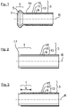
- a known pipe end 1 of a brake line 3 for a motor vehicle is shown.
- the pipe end 1 has a flanged head 5 which can be connected in a fluid-tight manner to a brake pressure transducer, for example, by means of a union nut (not shown).
- the flanging head 5 has a metallically pure, conical sealing surface 7 on the front side, which is smooth all around, free of cracks and grooves.
- the tube end 1 is designed to be rotationally symmetrical about the tube axis R.
- the brake line 3 and thus also the tube end 1 is constructed in several layers, namely with a radially inner steel tube 9, on which an aluminum or zinc layer 11 is applied for corrosion protection.
- the steel pipe 9 and the zinc layer 11 form a metallic pipe core 13 which is encased on the outside with a plastic coating 15, in particular a PA layer.
- a brake line 3 is provided with a pipe end 1 that has not yet been machined.
- a chamfering tool (not shown)
- the free end face of the pipe end 1 is machined flat and the end face outer edge 17 of the pipe end 1 is also chamfered.
- the resulting material removal during the chamfering process is in the 2 indicated with dotted lines.
- the method step illustrated in the method step involves stripping or stripping the pipe end 1, in which the plastic coating 15 is removed from the pipe end 1 over a predetermined stripping length e, exposing the zinc layer 11.
- the resulting material removal is in the 3 also indicated with dashed lines.
- the invention relates in particular to the 2 indicated step for stripping the pipe end 1.
- the tool shown is provided, the structure and mode of operation of which is described below:
- the tool 19 has a drive spindle 21 which merges into an approximately disk-shaped carrier 23 .
- a total of four roller elements 25 (or cutting bushes) are rotatably mounted about an axis of rotation D on the carrier 23 .
- the axes of rotation D of the roller elements 25 are arranged eccentrically with respect to the drive spindle 21 .
- the four roller elements 25 are also mounted on the carrier 23 via carriages 27 so that they can be radially adjusted. How from the Figures 4 to 7 further shows that the four roller elements 25 with their roller surfaces 29 delimit a central receiving space 31, into which the pipe end 1 to be stripped (in one, in the 2 state shown) can retract over an intended stripping length e.
- the four roller elements 25 are spaced apart from one another in such a way that the pipe end 1 to be stripped is inserted into the receiving space 31 with a press fit. That is, the four roller elements 25 press with their roller surfaces 29 each with a contact pressure F A ( 7 ) against the outer circumference of the pipe end to be stripped 1.
- the tube axis R and the axes of rotation D are arranged axially parallel to one another, so that each of the roller elements 25 with its roller surfaces 29 is in continuous line contact with the plastic coating 15 to be detached over the entire intended stripping length e.
- the roller elements 25 each have a molded embossed edge 35 on their peripheral edges facing away from the carrier 23, which embossed edge 35 protrudes radially outwards from the roller surfaces 29 with a slight oversize ⁇ h.
- the embossed edges 35 of the roller elements 25 produce a circumferential predetermined breaking edge in the plastic coating 15.
- the stripping tool 19 After inserting the pipe end 1 into the receiving space 31, the stripping tool 19 is rotated. As a result, the roller elements 25 are rotated around the pipe end 1 in a rolling process. The roller elements 25 are each in rolling contact with the contact pressure F A with the plastic coating 15 to be detached. In this way, the plastic coating 15 is subjected to flexing in the area of the pipe end 1, during which the microstructure of the plastic coating 15 changes and makes it brittle. As a result, the plastic coating 15 can be detached from the tubular core 13 without leaving any residue and at the same time can be torn off from the predetermined breaking point formed by the embossed edges 35 . In this way, a process-reliable, sharp tear-off edge for the remaining plastic coating 15 is produced.
- the oversize ⁇ h of the cutting edges 35 is smaller than the material thickness s ( 7 ) of the plastic coating 15 to be removed.
Landscapes
- Engineering & Computer Science (AREA)
- General Engineering & Computer Science (AREA)
- Mechanical Engineering (AREA)
- Chemical & Material Sciences (AREA)
- Combustion & Propulsion (AREA)
- Physics & Mathematics (AREA)
- Optics & Photonics (AREA)
- Transportation (AREA)
- Turning (AREA)
Claims (10)
- Dispositif servant à dénuder une extrémité de tuyau (1) d'un conduit de liquide de frein ou de carburant (2) revêtu d'un revêtement en plastique (15), qui présente une partie centrale de tube (13) métallique, caractérisé en ce que le dispositif présente au moins un élément de pression (25), avec lequel le revêtement en plastique (15) peut être décollé de la partie centrale de tube (13) par un usinage par foulage mécanique, dans lequel le revêtement en plastique (15) est soumis en alternance à une contrainte de pression et à un relâchement de pression, et en ce que la contrainte de pression et le relâchement de pression par l'élément de pression (25) présentent des valeurs telles que le revêtement en plastique (15) se fragilise lors de l'usinage par foulage en changeant la structure d'assemblage.
- Dispositif selon la revendication 1, caractérisé en ce que l'élément de pression (25) est un élément rouleau monté de manière à pouvoir tourner, lequel peut être amené en contact de roulement avec l'extrémité de tube (1) à dénuder par une force de compression (FA), et que l'usinage par foulage est effectué par une opération de déroulement de l'élément rouleau (25) sur l'extrémité de tube (1) à dénuder.
- Dispositif selon la revendication 1 ou 2, caractérisé en ce que l'élément rouleau (25) peut tourner autour d'un axe de rotation (D), qui est positionné de manière axialement parallèle par rapport à l'axe longitudinal (R) de l'extrémité de tube (1), et/ou que l'élément rouleau (25) est en continu en contact linéaire avec l'extrémité de tube (1) à dénuder par sa surface de roulement (29) sur une longueur de dénudage (e) prédéfinie.
- Dispositif selon l'une quelconque des revendications précédentes, caractérisé en ce qu'un élément de découpage (35) est prévu, avec lequel une arête de rupture théorique (14) peut être fixée, au niveau de laquelle le revêtement en plastique (15) se déchire lors de l'usinage par foulage.
- Dispositif selon la revendication 4, caractérisé en ce que l'élément de découpage (35) est une arête de découpage formée au niveau de l'élément rouleau (25), et qu'en particulier l'arête de découpage dépasse la surface de roulement (29) de l'élément rouleau (25) d'une dimension supérieure (Δh) prédéfinie, dans lequel la dimension supérieure (Δh) de l'arête de découpage (35) est en particulier plus petite que l'épaisseur de matériau (s) du revêtement en plastique (15) à enlever.
- Dispositif selon l'une quelconque des revendications précédentes, caractérisé en ce que l'axe de rotation (D) de l'élément rouleau (25) est monté de manière à pouvoir tourner autour de l'axe longitudinal (R) de l'extrémité de tube (1) aux fins de la réalisation de l'opération de déroulement.
- Dispositif selon l'une quelconque des revendications 2 à 6, caractérisé en ce qu'un nombre donné d'éléments rouleaux (25) est prévu, lesquels sont disposés en particulier selon une répartition homogène en périphérie autour de l'extrémité de tube (1).
- Dispositif selon la revendication 7, caractérisé en ce que les éléments rouleaux (25) délimitent, par leurs surfaces de rouleau (29), un espace de réception (31), dans lequel l'extrémité de tube (1) à dénuder peut être emboîtée, et ce en particulier par un ajustement par serrage, lors duquel les éléments rouleaux (25) exercent une pression contre l'extrémité de tube (1) avec la force de compression (FA),
- Dispositif selon la revendication 8, caractérisé en ce que le dispositif présente un outil de chanfreinage, avec lequel l'arête extérieure (17) côté frontal de l'extrémité de tube (1) peut être chanfreinée avant le dénudage, l'extrémité de tube (1) étant ainsi enfilée de manière simplifiée dans l'espace de réception (31).
- Procédé servant à dénuder une extrémité de tube (1) d'un conduit de liquide de frein ou de carburant (2) revêtu d'un revêtement en plastique (15), en particulier au moyen d'un dispositif selon l'une quelconque des revendications précédentes, où un usinage par foulage mécanique du revêtement en plastique (15) est effectué, dans lequel le revêtement en plastique (15) est soumis en alternance à une contrainte de pression et à un relâchement de pression et est décollé par la suite de la partie centrale de tube (13), la contrainte de pression et le relâchement de pression par l'élément de pression (25) présentant des valeurs telles que le revêtement en plastique (15) se fragilise lors de l'usinage par foulage en changeant la structure d'assemblage.
Applications Claiming Priority (1)
| Application Number | Priority Date | Filing Date | Title |
|---|---|---|---|
| DE102013011213.3A DE102013011213B3 (de) | 2013-07-04 | 2013-07-04 | Vorrichtung zum Entmanteln eines Rohrendes einer mit einer Kunststoffbeschichtung beschichteten Brems- oder Kraftstoffleitung |
Publications (3)
| Publication Number | Publication Date |
|---|---|
| EP2837536A1 EP2837536A1 (fr) | 2015-02-18 |
| EP2837536B1 EP2837536B1 (fr) | 2016-11-30 |
| EP2837536B2 true EP2837536B2 (fr) | 2022-04-06 |
Family
ID=51014168
Family Applications (1)
| Application Number | Title | Priority Date | Filing Date |
|---|---|---|---|
| EP14174058.9A Active EP2837536B2 (fr) | 2013-07-04 | 2014-06-26 | Dispositif destiné à dénuder une extrémité de tuyau d'une conduite de frein ou de carburant revêtue d'une couche en matière synthétique |
Country Status (2)
| Country | Link |
|---|---|
| EP (1) | EP2837536B2 (fr) |
| DE (1) | DE102013011213B3 (fr) |
Families Citing this family (5)
| Publication number | Priority date | Publication date | Assignee | Title |
|---|---|---|---|---|
| DE102015105798B4 (de) | 2015-01-23 | 2016-12-08 | Cooper-Standard Automotive (Deutschland) Gmbh | Verfahren zum Herstellen einer Rohrleitung, insbesondere einer Bremsrohrleitung oder Kraftstoffrohrleitung für ein Kraftfahrzeug, sowie eine solche Rohrleitung |
| DE102016210887A1 (de) | 2016-06-17 | 2017-12-21 | Cooper-Standard Automotive (Deutschland) Gmbh | Verfahren zum Herstellen einer Rohrleitung, insbesondere Bremsrohrleitung oder Kraftstoffrohrleitung für ein Kraftfahrzeug, sowie eine solche Rohrleitung |
| TWI598191B (zh) | 2016-09-12 | 2017-09-11 | Tai-Hung Lee | Part of the outer metal scraper hand tool with a non-metallic outer composite metal tube |
| DE102019135827A1 (de) * | 2019-12-27 | 2021-07-01 | Cooper-Standard Automotive (Deutschland) Gmbh | Überwurfschraube für mit wenigstens einem Bördel versehene Rohrleitungen, insbesondere Bremsrohre |
| WO2026006223A1 (fr) * | 2024-06-24 | 2026-01-02 | Cummins Inc. | Raccordement étanche dans un pipeline d'hydrogène haute pression |
Citations (6)
| Publication number | Priority date | Publication date | Assignee | Title |
|---|---|---|---|---|
| US3965570A (en) † | 1975-04-21 | 1976-06-29 | The Weatherhead Company | Hose skiving tool |
| WO1985002816A1 (fr) † | 1983-12-23 | 1985-07-04 | Ellett William A | Procede et dispositif permettant d'enlever le revetement protecteur d'une portion de conduite |
| DE29510705U1 (de) † | 1995-07-01 | 1995-10-19 | Jet Laser Systeme Gesellschaft für Oberflächentechnik mbH, 41836 Hückelhoven | Vorrichtung zum Entfernen einer Beschichtung von einem im wesentlichen rotationssymmetrischen Werkstück mittels Laserstrahlung |
| DE20214365U1 (de) † | 2002-09-16 | 2002-11-21 | Klann Tools Ltd., Oxfordshire | Vorrichtung zum Entmanteln einer Bremsleitung |
| DE10140925A1 (de) † | 2001-08-15 | 2003-03-13 | Itt Mfg Enterprises Inc | Vorrichtung zum Entschichten von Rohren |
| DE102008043876A1 (de) † | 2008-11-19 | 2010-05-20 | Robert Bosch Gmbh | Verfahren und Vorrichtung zum Abisolieren eines isolierten Drahtes |
-
2013
- 2013-07-04 DE DE102013011213.3A patent/DE102013011213B3/de active Active
-
2014
- 2014-06-26 EP EP14174058.9A patent/EP2837536B2/fr active Active
Patent Citations (6)
| Publication number | Priority date | Publication date | Assignee | Title |
|---|---|---|---|---|
| US3965570A (en) † | 1975-04-21 | 1976-06-29 | The Weatherhead Company | Hose skiving tool |
| WO1985002816A1 (fr) † | 1983-12-23 | 1985-07-04 | Ellett William A | Procede et dispositif permettant d'enlever le revetement protecteur d'une portion de conduite |
| DE29510705U1 (de) † | 1995-07-01 | 1995-10-19 | Jet Laser Systeme Gesellschaft für Oberflächentechnik mbH, 41836 Hückelhoven | Vorrichtung zum Entfernen einer Beschichtung von einem im wesentlichen rotationssymmetrischen Werkstück mittels Laserstrahlung |
| DE10140925A1 (de) † | 2001-08-15 | 2003-03-13 | Itt Mfg Enterprises Inc | Vorrichtung zum Entschichten von Rohren |
| DE20214365U1 (de) † | 2002-09-16 | 2002-11-21 | Klann Tools Ltd., Oxfordshire | Vorrichtung zum Entmanteln einer Bremsleitung |
| DE102008043876A1 (de) † | 2008-11-19 | 2010-05-20 | Robert Bosch Gmbh | Verfahren und Vorrichtung zum Abisolieren eines isolierten Drahtes |
Also Published As
| Publication number | Publication date |
|---|---|
| DE102013011213B3 (de) | 2014-10-30 |
| EP2837536A1 (fr) | 2015-02-18 |
| EP2837536B1 (fr) | 2016-11-30 |
Similar Documents
| Publication | Publication Date | Title |
|---|---|---|
| EP2837536B2 (fr) | Dispositif destiné à dénuder une extrémité de tuyau d'une conduite de frein ou de carburant revêtue d'une couche en matière synthétique | |
| DE102008024313A1 (de) | Verfahren zur Vorkonditionierung einer zu beschichtenden Oberfläche | |
| EP2289659A1 (fr) | Dispositif de liaison par friction d'au moins deux plaques au moyen d'un élément de liaison avec un système de mesure de l'effort appliqué et du déplacement durant la liaison | |
| EP2659158B1 (fr) | Disque de frein et procédé servant à traiter la surface d'un disque de frein | |
| DE102013000574A1 (de) | Rührreibschweißvorrichtung | |
| DE68922370T2 (de) | Vorrichtung zum Anbringen von Hüllen auf elektrische Kabelverbindungen. | |
| DE102005004754A1 (de) | Verfahren zur Nachreinigung von abisolierten Bereichen einer elektrischen Leitung | |
| EP2514589A1 (fr) | Procédé de fabrication d'une structure porteuse à recouvrement partiel | |
| EP2167254A2 (fr) | Procédé de fabrication d'un moyeu selon un procédé d'emboutissage au moyen d'au moins un cylindre d'emboutissage rotatif | |
| WO2010048931A1 (fr) | Dispositif de recouvrement partiel d'une partie de composant | |
| DE102019121563A1 (de) | Verfahren zur Herstellung eines Bauteils sowie Bauteil hierzu | |
| DE102019213464A1 (de) | Verfahren zum Herstellen eines Reibbremskörpers für eine Reibbremse eines Kraftfahrzeugs | |
| EP3470186B1 (fr) | Procédé et dispositif de dénudage des conduits préisolés | |
| DE102011078591A1 (de) | Verfahren zum Herstellen eines bereichsweise mit einer Beschichtung versehenen Substrats | |
| WO2008154940A1 (fr) | Procédé de réparation d'une zone d'une couche d'isolation thermique | |
| EP1656235B1 (fr) | Procede de fabrication de composants | |
| DE19820498A1 (de) | Verfahren zum Herstellen einer Hülse, insbesondere für die Druckindustrie | |
| DE102011005644A1 (de) | Verfahren zur Herstellung einer Funktionsoberfläche auf einem metallischen Bauteil | |
| EP3550684B1 (fr) | Dénudage de conduites électriques par ultrasons | |
| EP2045092A2 (fr) | Manchon en caoutchouc | |
| DE102014202066A1 (de) | Bohrvorrichtung und Verfahren zum Einbringen einer Bohrung | |
| DE102024104592A1 (de) | Verfahren zum Bearbeiten von Drähten zur Herstellung eines Drahtkorbs sowie Drahtkorb, insbesondere Wasch- oder Spülkorb, oder Teil davon | |
| DE2320211B2 (de) | Fertigbauteil fuer einen schacht, insbesondere muellabwurfschacht, aus einem mehrschichtigen flachmaterial sowie verfahren zur herstellung des fertigbauteils und von zuschnitten hierfuer | |
| EP1103317A2 (fr) | Procédé et dispositif de poinçonnage des pièces en tôle d' aluminium | |
| DE102013209614A1 (de) | Verfahren zur Herstellung eines strukturierten Bauteils |
Legal Events
| Date | Code | Title | Description |
|---|---|---|---|
| 17P | Request for examination filed |
Effective date: 20140626 |
|
| AK | Designated contracting states |
Kind code of ref document: A1 Designated state(s): AL AT BE BG CH CY CZ DE DK EE ES FI FR GB GR HR HU IE IS IT LI LT LU LV MC MK MT NL NO PL PT RO RS SE SI SK SM TR |
|
| AX | Request for extension of the european patent |
Extension state: BA ME |
|
| PUAI | Public reference made under article 153(3) epc to a published international application that has entered the european phase |
Free format text: ORIGINAL CODE: 0009012 |
|
| R17P | Request for examination filed (corrected) |
Effective date: 20150818 |
|
| RBV | Designated contracting states (corrected) |
Designated state(s): AL AT BE BG CH CY CZ DE DK EE ES FI FR GB GR HR HU IE IS IT LI LT LU LV MC MK MT NL NO PL PT RO RS SE SI SK SM TR |
|
| GRAP | Despatch of communication of intention to grant a patent |
Free format text: ORIGINAL CODE: EPIDOSNIGR1 |
|
| RIC1 | Information provided on ipc code assigned before grant |
Ipc: B60T 17/04 20060101AFI20160629BHEP Ipc: B23D 79/12 20060101ALI20160629BHEP |
|
| INTG | Intention to grant announced |
Effective date: 20160721 |
|
| GRAS | Grant fee paid |
Free format text: ORIGINAL CODE: EPIDOSNIGR3 |
|
| GRAA | (expected) grant |
Free format text: ORIGINAL CODE: 0009210 |
|
| AK | Designated contracting states |
Kind code of ref document: B1 Designated state(s): AL AT BE BG CH CY CZ DE DK EE ES FI FR GB GR HR HU IE IS IT LI LT LU LV MC MK MT NL NO PL PT RO RS SE SI SK SM TR |
|
| REG | Reference to a national code |
Ref country code: CH Ref legal event code: EP Ref country code: GB Ref legal event code: FG4D Free format text: NOT ENGLISH |
|
| REG | Reference to a national code |
Ref country code: AT Ref legal event code: REF Ref document number: 849488 Country of ref document: AT Kind code of ref document: T Effective date: 20161215 |
|
| REG | Reference to a national code |
Ref country code: IE Ref legal event code: FG4D Free format text: LANGUAGE OF EP DOCUMENT: GERMAN |
|
| REG | Reference to a national code |
Ref country code: DE Ref legal event code: R096 Ref document number: 502014002071 Country of ref document: DE |
|
| PG25 | Lapsed in a contracting state [announced via postgrant information from national office to epo] |
Ref country code: LV Free format text: LAPSE BECAUSE OF FAILURE TO SUBMIT A TRANSLATION OF THE DESCRIPTION OR TO PAY THE FEE WITHIN THE PRESCRIBED TIME-LIMIT Effective date: 20161130 |
|
| REG | Reference to a national code |
Ref country code: LT Ref legal event code: MG4D |
|
| REG | Reference to a national code |
Ref country code: NL Ref legal event code: MP Effective date: 20161130 |
|
| PG25 | Lapsed in a contracting state [announced via postgrant information from national office to epo] |
Ref country code: NO Free format text: LAPSE BECAUSE OF FAILURE TO SUBMIT A TRANSLATION OF THE DESCRIPTION OR TO PAY THE FEE WITHIN THE PRESCRIBED TIME-LIMIT Effective date: 20170228 Ref country code: GR Free format text: LAPSE BECAUSE OF FAILURE TO SUBMIT A TRANSLATION OF THE DESCRIPTION OR TO PAY THE FEE WITHIN THE PRESCRIBED TIME-LIMIT Effective date: 20170301 Ref country code: SE Free format text: LAPSE BECAUSE OF FAILURE TO SUBMIT A TRANSLATION OF THE DESCRIPTION OR TO PAY THE FEE WITHIN THE PRESCRIBED TIME-LIMIT Effective date: 20161130 Ref country code: LT Free format text: LAPSE BECAUSE OF FAILURE TO SUBMIT A TRANSLATION OF THE DESCRIPTION OR TO PAY THE FEE WITHIN THE PRESCRIBED TIME-LIMIT Effective date: 20161130 |
|
| PG25 | Lapsed in a contracting state [announced via postgrant information from national office to epo] |
Ref country code: HR Free format text: LAPSE BECAUSE OF FAILURE TO SUBMIT A TRANSLATION OF THE DESCRIPTION OR TO PAY THE FEE WITHIN THE PRESCRIBED TIME-LIMIT Effective date: 20161130 Ref country code: FI Free format text: LAPSE BECAUSE OF FAILURE TO SUBMIT A TRANSLATION OF THE DESCRIPTION OR TO PAY THE FEE WITHIN THE PRESCRIBED TIME-LIMIT Effective date: 20161130 Ref country code: ES Free format text: LAPSE BECAUSE OF FAILURE TO SUBMIT A TRANSLATION OF THE DESCRIPTION OR TO PAY THE FEE WITHIN THE PRESCRIBED TIME-LIMIT Effective date: 20161130 Ref country code: RS Free format text: LAPSE BECAUSE OF FAILURE TO SUBMIT A TRANSLATION OF THE DESCRIPTION OR TO PAY THE FEE WITHIN THE PRESCRIBED TIME-LIMIT Effective date: 20161130 Ref country code: PT Free format text: LAPSE BECAUSE OF FAILURE TO SUBMIT A TRANSLATION OF THE DESCRIPTION OR TO PAY THE FEE WITHIN THE PRESCRIBED TIME-LIMIT Effective date: 20170330 Ref country code: PL Free format text: LAPSE BECAUSE OF FAILURE TO SUBMIT A TRANSLATION OF THE DESCRIPTION OR TO PAY THE FEE WITHIN THE PRESCRIBED TIME-LIMIT Effective date: 20161130 |
|
| REG | Reference to a national code |
Ref country code: FR Ref legal event code: PLFP Year of fee payment: 4 |
|
| PG25 | Lapsed in a contracting state [announced via postgrant information from national office to epo] |
Ref country code: NL Free format text: LAPSE BECAUSE OF FAILURE TO SUBMIT A TRANSLATION OF THE DESCRIPTION OR TO PAY THE FEE WITHIN THE PRESCRIBED TIME-LIMIT Effective date: 20161130 |
|
| PG25 | Lapsed in a contracting state [announced via postgrant information from national office to epo] |
Ref country code: DK Free format text: LAPSE BECAUSE OF FAILURE TO SUBMIT A TRANSLATION OF THE DESCRIPTION OR TO PAY THE FEE WITHIN THE PRESCRIBED TIME-LIMIT Effective date: 20161130 Ref country code: EE Free format text: LAPSE BECAUSE OF FAILURE TO SUBMIT A TRANSLATION OF THE DESCRIPTION OR TO PAY THE FEE WITHIN THE PRESCRIBED TIME-LIMIT Effective date: 20161130 Ref country code: SK Free format text: LAPSE BECAUSE OF FAILURE TO SUBMIT A TRANSLATION OF THE DESCRIPTION OR TO PAY THE FEE WITHIN THE PRESCRIBED TIME-LIMIT Effective date: 20161130 Ref country code: RO Free format text: LAPSE BECAUSE OF FAILURE TO SUBMIT A TRANSLATION OF THE DESCRIPTION OR TO PAY THE FEE WITHIN THE PRESCRIBED TIME-LIMIT Effective date: 20161130 Ref country code: CZ Free format text: LAPSE BECAUSE OF FAILURE TO SUBMIT A TRANSLATION OF THE DESCRIPTION OR TO PAY THE FEE WITHIN THE PRESCRIBED TIME-LIMIT Effective date: 20161130 |
|
| REG | Reference to a national code |
Ref country code: DE Ref legal event code: R026 Ref document number: 502014002071 Country of ref document: DE |
|
| PLBI | Opposition filed |
Free format text: ORIGINAL CODE: 0009260 |
|
| PG25 | Lapsed in a contracting state [announced via postgrant information from national office to epo] |
Ref country code: SM Free format text: LAPSE BECAUSE OF FAILURE TO SUBMIT A TRANSLATION OF THE DESCRIPTION OR TO PAY THE FEE WITHIN THE PRESCRIBED TIME-LIMIT Effective date: 20161130 Ref country code: BG Free format text: LAPSE BECAUSE OF FAILURE TO SUBMIT A TRANSLATION OF THE DESCRIPTION OR TO PAY THE FEE WITHIN THE PRESCRIBED TIME-LIMIT Effective date: 20170228 Ref country code: IT Free format text: LAPSE BECAUSE OF FAILURE TO SUBMIT A TRANSLATION OF THE DESCRIPTION OR TO PAY THE FEE WITHIN THE PRESCRIBED TIME-LIMIT Effective date: 20161130 |
|
| 26 | Opposition filed |
Opponent name: COOPER-STANDARD AUTOMOTIVE (DEUTSCHLAND) GMBH Effective date: 20170821 |
|
| PLAX | Notice of opposition and request to file observation + time limit sent |
Free format text: ORIGINAL CODE: EPIDOSNOBS2 |
|
| PG25 | Lapsed in a contracting state [announced via postgrant information from national office to epo] |
Ref country code: SI Free format text: LAPSE BECAUSE OF FAILURE TO SUBMIT A TRANSLATION OF THE DESCRIPTION OR TO PAY THE FEE WITHIN THE PRESCRIBED TIME-LIMIT Effective date: 20161130 |
|
| PG25 | Lapsed in a contracting state [announced via postgrant information from national office to epo] |
Ref country code: MC Free format text: LAPSE BECAUSE OF FAILURE TO SUBMIT A TRANSLATION OF THE DESCRIPTION OR TO PAY THE FEE WITHIN THE PRESCRIBED TIME-LIMIT Effective date: 20161130 |
|
| REG | Reference to a national code |
Ref country code: CH Ref legal event code: PL |
|
| PLBB | Reply of patent proprietor to notice(s) of opposition received |
Free format text: ORIGINAL CODE: EPIDOSNOBS3 |
|
| REG | Reference to a national code |
Ref country code: IE Ref legal event code: MM4A |
|
| PG25 | Lapsed in a contracting state [announced via postgrant information from national office to epo] |
Ref country code: IE Free format text: LAPSE BECAUSE OF NON-PAYMENT OF DUE FEES Effective date: 20170626 Ref country code: CH Free format text: LAPSE BECAUSE OF NON-PAYMENT OF DUE FEES Effective date: 20170630 Ref country code: LI Free format text: LAPSE BECAUSE OF NON-PAYMENT OF DUE FEES Effective date: 20170630 Ref country code: LU Free format text: LAPSE BECAUSE OF NON-PAYMENT OF DUE FEES Effective date: 20170626 |
|
| REG | Reference to a national code |
Ref country code: BE Ref legal event code: MM Effective date: 20170630 |
|
| REG | Reference to a national code |
Ref country code: FR Ref legal event code: PLFP Year of fee payment: 5 |
|
| PG25 | Lapsed in a contracting state [announced via postgrant information from national office to epo] |
Ref country code: BE Free format text: LAPSE BECAUSE OF NON-PAYMENT OF DUE FEES Effective date: 20170630 |
|
| PG25 | Lapsed in a contracting state [announced via postgrant information from national office to epo] |
Ref country code: MT Free format text: LAPSE BECAUSE OF FAILURE TO SUBMIT A TRANSLATION OF THE DESCRIPTION OR TO PAY THE FEE WITHIN THE PRESCRIBED TIME-LIMIT Effective date: 20161130 |
|
| PLCK | Communication despatched that opposition was rejected |
Free format text: ORIGINAL CODE: EPIDOSNREJ1 |
|
| STAA | Information on the status of an ep patent application or granted ep patent |
Free format text: STATUS: THE PATENT HAS BEEN GRANTED |
|
| APBM | Appeal reference recorded |
Free format text: ORIGINAL CODE: EPIDOSNREFNO |
|
| APBP | Date of receipt of notice of appeal recorded |
Free format text: ORIGINAL CODE: EPIDOSNNOA2O |
|
| APAH | Appeal reference modified |
Free format text: ORIGINAL CODE: EPIDOSCREFNO |
|
| PG25 | Lapsed in a contracting state [announced via postgrant information from national office to epo] |
Ref country code: HU Free format text: LAPSE BECAUSE OF FAILURE TO SUBMIT A TRANSLATION OF THE DESCRIPTION OR TO PAY THE FEE WITHIN THE PRESCRIBED TIME-LIMIT; INVALID AB INITIO Effective date: 20140626 |
|
| APBQ | Date of receipt of statement of grounds of appeal recorded |
Free format text: ORIGINAL CODE: EPIDOSNNOA3O |
|
| PG25 | Lapsed in a contracting state [announced via postgrant information from national office to epo] |
Ref country code: CY Free format text: LAPSE BECAUSE OF FAILURE TO SUBMIT A TRANSLATION OF THE DESCRIPTION OR TO PAY THE FEE WITHIN THE PRESCRIBED TIME-LIMIT Effective date: 20161130 |
|
| PG25 | Lapsed in a contracting state [announced via postgrant information from national office to epo] |
Ref country code: MK Free format text: LAPSE BECAUSE OF FAILURE TO SUBMIT A TRANSLATION OF THE DESCRIPTION OR TO PAY THE FEE WITHIN THE PRESCRIBED TIME-LIMIT Effective date: 20161130 |
|
| PG25 | Lapsed in a contracting state [announced via postgrant information from national office to epo] |
Ref country code: TR Free format text: LAPSE BECAUSE OF FAILURE TO SUBMIT A TRANSLATION OF THE DESCRIPTION OR TO PAY THE FEE WITHIN THE PRESCRIBED TIME-LIMIT Effective date: 20161130 |
|
| PG25 | Lapsed in a contracting state [announced via postgrant information from national office to epo] |
Ref country code: AL Free format text: LAPSE BECAUSE OF FAILURE TO SUBMIT A TRANSLATION OF THE DESCRIPTION OR TO PAY THE FEE WITHIN THE PRESCRIBED TIME-LIMIT Effective date: 20161130 Ref country code: IS Free format text: LAPSE BECAUSE OF FAILURE TO SUBMIT A TRANSLATION OF THE DESCRIPTION OR TO PAY THE FEE WITHIN THE PRESCRIBED TIME-LIMIT Effective date: 20170330 |
|
| REG | Reference to a national code |
Ref country code: AT Ref legal event code: MM01 Ref document number: 849488 Country of ref document: AT Kind code of ref document: T Effective date: 20190626 |
|
| PG25 | Lapsed in a contracting state [announced via postgrant information from national office to epo] |
Ref country code: AT Free format text: LAPSE BECAUSE OF NON-PAYMENT OF DUE FEES Effective date: 20190626 |
|
| PLAB | Opposition data, opponent's data or that of the opponent's representative modified |
Free format text: ORIGINAL CODE: 0009299OPPO |
|
| R26 | Opposition filed (corrected) |
Opponent name: COOPER-STANDARD AUTOMOTIVE (DEUTSCHLAND) GMBH Effective date: 20170821 |
|
| APBU | Appeal procedure closed |
Free format text: ORIGINAL CODE: EPIDOSNNOA9O |
|
| PUAH | Patent maintained in amended form |
Free format text: ORIGINAL CODE: 0009272 |
|
| STAA | Information on the status of an ep patent application or granted ep patent |
Free format text: STATUS: PATENT MAINTAINED AS AMENDED |
|
| 27A | Patent maintained in amended form |
Effective date: 20220406 |
|
| AK | Designated contracting states |
Kind code of ref document: B2 Designated state(s): AL AT BE BG CH CY CZ DE DK EE ES FI FR GB GR HR HU IE IS IT LI LT LU LV MC MK MT NL NO PL PT RO RS SE SI SK SM TR |
|
| REG | Reference to a national code |
Ref country code: DE Ref legal event code: R102 Ref document number: 502014002071 Country of ref document: DE |
|
| P01 | Opt-out of the competence of the unified patent court (upc) registered |
Effective date: 20230530 |
|
| PGFP | Annual fee paid to national office [announced via postgrant information from national office to epo] |
Ref country code: DE Payment date: 20250630 Year of fee payment: 12 |
|
| PGFP | Annual fee paid to national office [announced via postgrant information from national office to epo] |
Ref country code: GB Payment date: 20250621 Year of fee payment: 12 |
|
| PGFP | Annual fee paid to national office [announced via postgrant information from national office to epo] |
Ref country code: FR Payment date: 20250617 Year of fee payment: 12 |