EP2838178A1 - Structure de réception d'énergie pour navire, dispositif d'alimentation électrique et procédé d'alimentation électrique - Google Patents
Structure de réception d'énergie pour navire, dispositif d'alimentation électrique et procédé d'alimentation électrique Download PDFInfo
- Publication number
- EP2838178A1 EP2838178A1 EP13775110.3A EP13775110A EP2838178A1 EP 2838178 A1 EP2838178 A1 EP 2838178A1 EP 13775110 A EP13775110 A EP 13775110A EP 2838178 A1 EP2838178 A1 EP 2838178A1
- Authority
- EP
- European Patent Office
- Prior art keywords
- power
- supplying
- coil
- ship
- receiving
- Prior art date
- Legal status (The legal status is an assumption and is not a legal conclusion. Google has not performed a legal analysis and makes no representation as to the accuracy of the status listed.)
- Withdrawn
Links
Images



Classifications
-
- B—PERFORMING OPERATIONS; TRANSPORTING
- B60—VEHICLES IN GENERAL
- B60L—PROPULSION OF ELECTRICALLY-PROPELLED VEHICLES; SUPPLYING ELECTRIC POWER FOR AUXILIARY EQUIPMENT OF ELECTRICALLY-PROPELLED VEHICLES; ELECTRODYNAMIC BRAKE SYSTEMS FOR VEHICLES IN GENERAL; MAGNETIC SUSPENSION OR LEVITATION FOR VEHICLES; MONITORING OPERATING VARIABLES OF ELECTRICALLY-PROPELLED VEHICLES; ELECTRIC SAFETY DEVICES FOR ELECTRICALLY-PROPELLED VEHICLES
- B60L53/00—Methods of charging batteries, specially adapted for electric vehicles; Charging stations or on-board charging equipment therefor; Exchange of energy storage elements in electric vehicles
- B60L53/10—Methods of charging batteries, specially adapted for electric vehicles; Charging stations or on-board charging equipment therefor; Exchange of energy storage elements in electric vehicles characterised by the energy transfer between the charging station and the vehicle
- B60L53/12—Inductive energy transfer
-
- B—PERFORMING OPERATIONS; TRANSPORTING
- B60—VEHICLES IN GENERAL
- B60L—PROPULSION OF ELECTRICALLY-PROPELLED VEHICLES; SUPPLYING ELECTRIC POWER FOR AUXILIARY EQUIPMENT OF ELECTRICALLY-PROPELLED VEHICLES; ELECTRODYNAMIC BRAKE SYSTEMS FOR VEHICLES IN GENERAL; MAGNETIC SUSPENSION OR LEVITATION FOR VEHICLES; MONITORING OPERATING VARIABLES OF ELECTRICALLY-PROPELLED VEHICLES; ELECTRIC SAFETY DEVICES FOR ELECTRICALLY-PROPELLED VEHICLES
- B60L53/00—Methods of charging batteries, specially adapted for electric vehicles; Charging stations or on-board charging equipment therefor; Exchange of energy storage elements in electric vehicles
- B60L53/30—Constructional details of charging stations
- B60L53/35—Means for automatic or assisted adjustment of the relative position of charging devices and vehicles
- B60L53/38—Means for automatic or assisted adjustment of the relative position of charging devices and vehicles specially adapted for charging by inductive energy transfer
-
- B—PERFORMING OPERATIONS; TRANSPORTING
- B63—SHIPS OR OTHER WATERBORNE VESSELS; RELATED EQUIPMENT
- B63J—AUXILIARIES ON VESSELS
- B63J99/00—Subject matter not provided for in other groups of this subclass
-
- H—ELECTRICITY
- H02—GENERATION; CONVERSION OR DISTRIBUTION OF ELECTRIC POWER
- H02J—ELECTRIC POWER NETWORKS; CIRCUIT ARRANGEMENTS OR SYSTEMS FOR SUPPLYING OR DISTRIBUTING ELECTRIC POWER; SYSTEMS FOR STORING ELECTRIC ENERGY
- H02J50/00—Circuit arrangements or systems for wireless supply or distribution of electric power
- H02J50/10—Circuit arrangements or systems for wireless supply or distribution of electric power using inductive coupling
- H02J50/12—Circuit arrangements or systems for wireless supply or distribution of electric power using inductive coupling of the resonant type
-
- H—ELECTRICITY
- H02—GENERATION; CONVERSION OR DISTRIBUTION OF ELECTRIC POWER
- H02J—ELECTRIC POWER NETWORKS; CIRCUIT ARRANGEMENTS OR SYSTEMS FOR SUPPLYING OR DISTRIBUTING ELECTRIC POWER; SYSTEMS FOR STORING ELECTRIC ENERGY
- H02J50/00—Circuit arrangements or systems for wireless supply or distribution of electric power
- H02J50/80—Circuit arrangements or systems for wireless supply or distribution of electric power involving the exchange of data, concerning supply or distribution of electric power, between transmitting devices and receiving devices
-
- H—ELECTRICITY
- H02—GENERATION; CONVERSION OR DISTRIBUTION OF ELECTRIC POWER
- H02J—ELECTRIC POWER NETWORKS; CIRCUIT ARRANGEMENTS OR SYSTEMS FOR SUPPLYING OR DISTRIBUTING ELECTRIC POWER; SYSTEMS FOR STORING ELECTRIC ENERGY
- H02J50/00—Circuit arrangements or systems for wireless supply or distribution of electric power
- H02J50/90—Circuit arrangements or systems for wireless supply or distribution of electric power involving detection or optimisation of position, e.g. alignment
-
- B—PERFORMING OPERATIONS; TRANSPORTING
- B60—VEHICLES IN GENERAL
- B60L—PROPULSION OF ELECTRICALLY-PROPELLED VEHICLES; SUPPLYING ELECTRIC POWER FOR AUXILIARY EQUIPMENT OF ELECTRICALLY-PROPELLED VEHICLES; ELECTRODYNAMIC BRAKE SYSTEMS FOR VEHICLES IN GENERAL; MAGNETIC SUSPENSION OR LEVITATION FOR VEHICLES; MONITORING OPERATING VARIABLES OF ELECTRICALLY-PROPELLED VEHICLES; ELECTRIC SAFETY DEVICES FOR ELECTRICALLY-PROPELLED VEHICLES
- B60L2200/00—Type of vehicles
- B60L2200/32—Waterborne vessels
-
- B—PERFORMING OPERATIONS; TRANSPORTING
- B60—VEHICLES IN GENERAL
- B60L—PROPULSION OF ELECTRICALLY-PROPELLED VEHICLES; SUPPLYING ELECTRIC POWER FOR AUXILIARY EQUIPMENT OF ELECTRICALLY-PROPELLED VEHICLES; ELECTRODYNAMIC BRAKE SYSTEMS FOR VEHICLES IN GENERAL; MAGNETIC SUSPENSION OR LEVITATION FOR VEHICLES; MONITORING OPERATING VARIABLES OF ELECTRICALLY-PROPELLED VEHICLES; ELECTRIC SAFETY DEVICES FOR ELECTRICALLY-PROPELLED VEHICLES
- B60L2240/00—Control parameters of input or output; Target parameters
- B60L2240/80—Time limits
-
- B—PERFORMING OPERATIONS; TRANSPORTING
- B63—SHIPS OR OTHER WATERBORNE VESSELS; RELATED EQUIPMENT
- B63H—MARINE PROPULSION OR STEERING
- B63H21/00—Use of propulsion power plant or units on vessels
-
- B—PERFORMING OPERATIONS; TRANSPORTING
- B63—SHIPS OR OTHER WATERBORNE VESSELS; RELATED EQUIPMENT
- B63J—AUXILIARIES ON VESSELS
- B63J3/00—Driving of auxiliaries
- B63J3/04—Driving of auxiliaries from power plant other than propulsion power plant
-
- H—ELECTRICITY
- H02—GENERATION; CONVERSION OR DISTRIBUTION OF ELECTRIC POWER
- H02J—ELECTRIC POWER NETWORKS; CIRCUIT ARRANGEMENTS OR SYSTEMS FOR SUPPLYING OR DISTRIBUTING ELECTRIC POWER; SYSTEMS FOR STORING ELECTRIC ENERGY
- H02J2105/00—Networks for supplying or distributing electric power characterised by their spatial reach or by the load
- H02J2105/30—Networks for supplying or distributing electric power characterised by their spatial reach or by the load the load networks being external to vehicles, i.e. exchanging power with vehicles
- H02J2105/31—Networks for supplying or distributing electric power characterised by their spatial reach or by the load the load networks being external to vehicles, i.e. exchanging power with vehicles for ships or vessels
-
- H—ELECTRICITY
- H02—GENERATION; CONVERSION OR DISTRIBUTION OF ELECTRIC POWER
- H02J—ELECTRIC POWER NETWORKS; CIRCUIT ARRANGEMENTS OR SYSTEMS FOR SUPPLYING OR DISTRIBUTING ELECTRIC POWER; SYSTEMS FOR STORING ELECTRIC ENERGY
- H02J50/00—Circuit arrangements or systems for wireless supply or distribution of electric power
- H02J50/005—Mechanical details of housing or structure aiming to accommodate the power transfer means, e.g. mechanical integration of coils, antennas or transducers into emitting or receiving devices
-
- Y—GENERAL TAGGING OF NEW TECHNOLOGICAL DEVELOPMENTS; GENERAL TAGGING OF CROSS-SECTIONAL TECHNOLOGIES SPANNING OVER SEVERAL SECTIONS OF THE IPC; TECHNICAL SUBJECTS COVERED BY FORMER USPC CROSS-REFERENCE ART COLLECTIONS [XRACs] AND DIGESTS
- Y02—TECHNOLOGIES OR APPLICATIONS FOR MITIGATION OR ADAPTATION AGAINST CLIMATE CHANGE
- Y02T—CLIMATE CHANGE MITIGATION TECHNOLOGIES RELATED TO TRANSPORTATION
- Y02T10/00—Road transport of goods or passengers
- Y02T10/60—Other road transportation technologies with climate change mitigation effect
- Y02T10/70—Energy storage systems for electromobility, e.g. batteries
-
- Y—GENERAL TAGGING OF NEW TECHNOLOGICAL DEVELOPMENTS; GENERAL TAGGING OF CROSS-SECTIONAL TECHNOLOGIES SPANNING OVER SEVERAL SECTIONS OF THE IPC; TECHNICAL SUBJECTS COVERED BY FORMER USPC CROSS-REFERENCE ART COLLECTIONS [XRACs] AND DIGESTS
- Y02—TECHNOLOGIES OR APPLICATIONS FOR MITIGATION OR ADAPTATION AGAINST CLIMATE CHANGE
- Y02T—CLIMATE CHANGE MITIGATION TECHNOLOGIES RELATED TO TRANSPORTATION
- Y02T10/00—Road transport of goods or passengers
- Y02T10/60—Other road transportation technologies with climate change mitigation effect
- Y02T10/7072—Electromobility specific charging systems or methods for batteries, ultracapacitors, supercapacitors or double-layer capacitors
-
- Y—GENERAL TAGGING OF NEW TECHNOLOGICAL DEVELOPMENTS; GENERAL TAGGING OF CROSS-SECTIONAL TECHNOLOGIES SPANNING OVER SEVERAL SECTIONS OF THE IPC; TECHNICAL SUBJECTS COVERED BY FORMER USPC CROSS-REFERENCE ART COLLECTIONS [XRACs] AND DIGESTS
- Y02—TECHNOLOGIES OR APPLICATIONS FOR MITIGATION OR ADAPTATION AGAINST CLIMATE CHANGE
- Y02T—CLIMATE CHANGE MITIGATION TECHNOLOGIES RELATED TO TRANSPORTATION
- Y02T90/00—Enabling technologies or technologies with a potential or indirect contribution to GHG emissions mitigation
- Y02T90/10—Technologies relating to charging of electric vehicles
- Y02T90/12—Electric charging stations
-
- Y—GENERAL TAGGING OF NEW TECHNOLOGICAL DEVELOPMENTS; GENERAL TAGGING OF CROSS-SECTIONAL TECHNOLOGIES SPANNING OVER SEVERAL SECTIONS OF THE IPC; TECHNICAL SUBJECTS COVERED BY FORMER USPC CROSS-REFERENCE ART COLLECTIONS [XRACs] AND DIGESTS
- Y02—TECHNOLOGIES OR APPLICATIONS FOR MITIGATION OR ADAPTATION AGAINST CLIMATE CHANGE
- Y02T—CLIMATE CHANGE MITIGATION TECHNOLOGIES RELATED TO TRANSPORTATION
- Y02T90/00—Enabling technologies or technologies with a potential or indirect contribution to GHG emissions mitigation
- Y02T90/10—Technologies relating to charging of electric vehicles
- Y02T90/14—Plug-in electric vehicles
Definitions
- the present invention relates to a ship power-receiving structure, a ship power-supplying device and a ship power-supplying method.
- Priority is claimed on Japanese Patent Application No. 2012-92176 filed on April 13, 2012 , the contents of which are incorporated herein by reference.
- Patent Document 1 An example of the power-supplying method is described in the following Patent Document 1.
- electric power is supplied in the following manner.
- a power-supplying coil is provided on a land-side and a power-receiving coil is provided on a ship-side.
- An alternating current having a high frequency (for example, 10 kHz to 30 kHz) is fed to the power-supplying coil, thereby generating electric power in the power-receiving coil.
- the electric power generated in the power-receiving coil is supplied to a power system provided in the ship.
- Patent Document 1 Japanese Unexamined Patent Application Publication (JP-A) No. 2010-11696
- the power-receiving coil is provided to be protruded from an outer wall of the ship. For this reason, there is a possibility that the power-receiving coil might disturb navigation.
- the power-receiving coil is pulled into the ship after receipt of electric power through the power-receiving coil is finished. In this case, a great deal of time and labor is required to pull the power-receiving coil in.
- the present invention is conceived in view of the above-described circumstances and it is an object thereof to provide a ship power-receiving structure, a ship power-supplying device and a ship power-supplying method in which a power-receiving coil provided on a ship-side supplies electric power from outside of the ship to the ship through the power-receiving coil, the power-receiving coil does not disturb navigation and a great deal of time and labor required to pull the power-receiving coil in the ship can be eliminated after the supply of electric power to the ship is finished.
- a power-receiving structure is a power-receiving structure that is provided in a ship and includes a power-receiving coil capable of wirelessly receiving electric power from a power-supplying coil on a land-side, and an outer wall surface-forming section forming an outer surface of side of the ship, and the power-receiving coil is provided on an inside of the ship from the outer wall surface-forming section, and an electromagnetic field-transmissive section formed of a material through which an electromagnetic field propagates is provided in an opposing portion to the power-receiving coil in the outer wall surface-forming section.
- the material of the electromagnetic field-transmissive section is plastic.
- the plastic is fiber reinforced plastic.
- a power-supplying device is a device configured to supply electric power to a ship having the power-receiving structure and includes a power-supplying coil, provided on a land-side, configured to supply electric power to the power-receiving coil through the electromagnetic field-transmissive section, a supply power measuring section configured to measure electric power supplied to the power-supplying coil, a receiving section configured to receive, from a ship-side, a measured value of electric power received from the power-supplying coil by the power-receiving coil, an efficiency calculating section configured to calculate the efficiency of electric power transmission from the power-supplying coil to the power-receiving coil based on the supplied electric power measured by the supply power measuring section and the measured value of the electric power received by the receiving section, a moving device, provided on the land-side, configured to move the power-supplying coil, and a control device configured to control the moving device to move the power-supplying coil based on the efficiency calculated by the efficiency calculating section, thereby adjusting a position of the power
- a power-supplying method is a power supplying method using the power-supplying device and includes a first step of disposing the power-supplying coil with respect to the power-receiving coil when the ship is moored, a second step of temporarily supplying electric power from the power-supplying coil to the power-receiving coil through the electromagnetic field-transmissive section, and a third step of calculating the efficiency of the electric power transmission from the power-supplying coil to the power-receiving coil in the second step by the efficiency calculating section, and the first to third steps are repeated a predetermined number of times while a position of the power-supplying coil with respect to the power-receiving coil is changed, and the power-supplying coil is disposed, by the control device, in a position of the power-supplying coil where the highest of the efficiencies calculated in the third step is obtained and electric power is continuously supplied from the power-supplying coil to the power-receiving coil in this state.
- a power-supplying method is a power supplying method using the power-supplying device and includes a calculating step of calculating an efficiency of the electric power transmission from the power-supplying coil to the power-receiving coil by the efficiency calculating section while continuously supplying electric power from the power-supplying coil to the power-receiving coil while the ship is moored, and the calculating step is repeated a predetermined number of times while a position of the power-supplying coil is changed by the moving device, and the power-supplying coil is disposed, by the control device, in a position of the power-supplying coil where the highest of the efficiencies calculated in the calculating step is obtained.
- a power-supplying device is a device configured to supply electric power to a ship having the power-receiving structure and includes a power-supplying coil, provided on a land-side, configured to supply electric power to the power-receiving coil through the electromagnetic field-transmissive section, a support supporting the power-supplying coil, and a suction device attached to the support, and the suction device adheres to an outer surface of side of the ship in a state in which the power-supplying coil opposes to the power-receiving coil through the electromagnetic field-transmissive section.
- the power-receiving coil is provided on the inside of the outer wall surface-forming section of the ship and the electromagnetic field-transmissive section formed of a material through which an electromagnetic field propagates is provided in the opposing portion to the power-receiving coil in the outer wall surface-forming section.
- the power-receiving coil is not protruded from the outer surface of side of the ship but can wirelessly receive electric power from the power-supplying coil on the land-side through the electromagnetic field-transmissive section.
- the power-receiving coil does not disturb the navigation of the ship and is not required to be pulled into the ship after the supply of the electric power to the ship is finished.
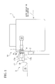
- FIG. 1 shows a ship 1 having a power-receiving structure 10 according to the embodiments of the present invention and a power-supplying device 3 according to a first embodiment of the present invention.
- FIG. 1 is a view showing the ship 1 seen in a front-rear direction.
- the ship 1 can wirelessly receive electric power by the power-receiving structure 10 without using a terminal from a power-supplying coil 5 of the power-supplying device 3 provided on a land.
- the power-receiving structure 10 includes a power-receiving coil 7 capable of wirelessly receiving electric power from the power-supplying coil 5 on a land-side when the ship 1 is moored at a shore and an outer wall surface-forming section 9 forming an outer surface of side of the ship 1 (that is, an outer surface of an outer plate of the ship).
- An electromagnetic field-transmissive section 9a is provided in an opposing portion to the power-receiving coil 7 in the outer wall surface-forming section 9.
- the electromagnetic field-transmissive section 9a is formed of a material through which an electromagnetic field (an electric field and a magnetic field) propagates.
- the electromagnetic field-transmissive section 9a is embedded in a through hole formed by boring a portion to which the power-receiving coil 7 is opposing.
- the power-receiving coil 7 is provided on an inside of the ship 1 from the outer wall surface-forming section 9.
- At least the opposing portion to the power-receiving coil 7 in the outer wall surface-forming section 9 is the electromagnetic field-transmissive section 9a formed of the material through which the electromagnetic field (the electric field and the magnetic field) propagates. Consequently, the power-receiving coil 7 can wirelessly receive electric power from the power-supplying coil 5 on the land-side through the electromagnetic field-transmissive section 9a.
- the material of the electromagnetic field-transmissive section 9a is preferably fiber reinforced plastic (FRP).
- FRP fiber reinforced plastic
- a fiber configured to reinforce plastic is a carbon fiber, a glass fiber, a polyethylene fiber, an aramid fiber or the like and plastic are impregnated in a fiber with an orientation of the fiber held, a plurality of fibers is superposed on each other in different fiber directions or fibers cut finely are mixed into plastic.
- the power-receiving coil 7 can be prevented from directly coming in contact with a support 41.
- the coil 7 or a member formed of a metal such as an electric wire can be prevented from being corroded by sea water. It is desirable that a portion between the electromagnetic field-transmissive section 9a and the outer wall surface-forming section 9 should be sealed with an elastic rubber or the like.
- the electromagnetic field-transmissive section 9a In the outer wall surface-forming section 9, it is possible that only a portion to which the power-receiving coil 7 is opposing in an axial direction thereof (a portion surrounded in a broken line A in FIG. 1 , for example) is the electromagnetic field-transmissive section 9a. Instead, the whole outer wall surface-forming section 9 of the ship 1 may be the electromagnetic field-transmissive section 9a.
- the power receiving coil 7 is not protruded from the outer surface of side of the ship 1 but can wirelessly receive electric power from the power-supplying coil 5 on the land-side through the electromagnetic field-transmissive section 9a.
- the power-receiving coil 7 does not disturb the navigation of the ship 1. Moreover, the power-receiving coil 7 is not required to be pulled into the ship 1 after supply of electric power to the ship 1 is finished. Therefore, a time required to start and stop the receipt of the electric power can be shortened.
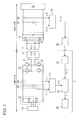
- FIG. 2 shows a circuit configuration including the power-supplying device 3 and the power-receiving coil 7.
- the power-supplying device 3 includes the power-supplying coil 5, a supply power measuring section 11, a receiving section 13, an efficiency calculating section 15, a moving device 17 and a control device 19 as is shown in FIGS. 1 and 2 .
- the power-supplying coil 5 is provided on the land-side.
- An electromagnetic coupling circuit is realized by the power-supplying coil 5 and the power-receiving coil 7 in a state in which the power-supplying coil 5 is close to the power-receiving coil 7. In this state, AC power is supplied to the power-supplying coil 5 so that the power-supplying coil 5 wirelessly transmits electric power to the power-receiving coil 7 via the electromagnetic field-transmissive section 9a.
- the electromagnetic coupling circuit uses an electromagnetic induction system or an electromagnetic field resonance system. In FIG. 2 , two capacitors 6 are connected to the power-supplying coil 5 in series and a capacitor 8 is connected to the power-receiving coil 7 in parallel.
- the supply power measuring section 11 measures electric power supplied to the power-supplying coil 5.
- the supply power measuring section 11 outputs a measured value P 1 (t) of electric power obtained by multiplying a measured value V 1 (t) of a voltage supplied to the power-supplying coil 5 and a measured value I 1 (t) of a current supplied to the power-supplying coil 5.
- the power-supplying device 3 is provided with a rectifier circuit 21, an inverter 23 and an external power supply 25.
- the rectifier circuit 21 coverts AC power from the external power supply 25 into DC power.
- the inverter 23 converts the DC power from the rectifier circuit 21 into AC power and supplies the AC power to the power-supplying coil 5.
- the measured value V 1 (t) of the voltage and the measured value I 1 (t) of the current are obtained by measuring a DC voltage and a direct current, respectively, from the rectifier circuit 21 between the rectifier circuit 21 and the inverter 23.
- the measured value V 1 (t) of the voltage and the measured value I 1 (t) of the current are measured by a voltage measuring device 27 and a current measuring device 29 shown in FIG. 2 , respectively.
- the receiving section 13 receives a measured value of a power receiving amount of the power-receiving coil 7 from the ship 1 side.
- a measured value (a measured value of electric power) P 2 (t) of the power receiving amount is obtained by multiplying a measured value V 2 (t) of a voltage supplied from the power-supplying coil 5 to the power-receiving coil 7 and a measured value I 2 (t) of a current supplied from the power-supplying coil 5 to the power receiving coil 7.
- the ship 1 is provided with a rectifier circuit 31, a power receiving amount measuring section 33 and a transmitting section 35.
- the rectifier circuit 31 converts AC power from the power-receiving coil 7 into DC power and supplies the DC power to a load 32 in the ship 1.
- An electricity storage device may be provided in place of the load 32.
- the power receiving amount measuring section 33 calculates, as the measured value P 2 (t) of the power receiving amount, a value obtained by multiplying a measured value V 2 (t) of a DC voltage from the rectifier circuit 31 and a measured value I 2 (t) of a direct current from the rectifier circuit 31.
- the measured value V 2 (t) of the voltage and the measured value I 2 (t) of the current are measured by a voltage measuring device 37 and a current measuring device 39 shown in FIG. 2 , respectively.
- the transmitting section 35 wirelessly transmits the measured value P 2 (t) of the electric power calculated by the power receiving amount measuring section 33 to the receiving section 13.
- the efficiency calculating section 15 measures an efficiency of electric power transmission from the power-supplying coil 5 to the power-receiving coil 7 based on the measured value P 1 (t) of the electric power measured by the supply power measuring section 11 and the measured value P 2 (t) of the electric power received from the transmitting section 35 on the ship 1 side.
- the moving device 17 is provided on the land-side and moves the power-supplying coil 5 with respect to the land, thereby changing a position of the power-supplying coil 5.
- the moving device 17 is configured to move the power-supplying coil 5 in a horizontal direction along the outer surface of side of the ship 1 and in a vertical direction, thereby enabling adjustment of the position of the power-supplying coil 5.
- the moving device 17 includes a mobile body 17a having the power-supplying coil 5 attached thereto, a moving mechanism 17b configured to move the mobile body 17a in the horizontal direction and in the vertical direction, and a motive power supply (not shown) configured to give motive power configured to move the mobile body 17a to the moving mechanism 17b.
- the moving device 17 may be configured to move the power-supplying coil 5 in the horizontal direction along the outer surface of side of the ship 1 and in the vertical direction, and furthermore, to move the power-supplying coil 5 in an direction perpendicular to the outer surface of side of the ship 1.
- Electric power is supplied by a cable 18 from the external power supply 25 that is stationary with respect to the land to the power-supplying coil 5 attached to the mobile body 17a that is moved with respect to the land.
- the cable 18 may be deformably flexed or may be freely wound off from a drum in order to follow a change in a position of the mobile body 17a of the moving device 17.
- the rectifier circuit 21 and the inverter 23 may be provided in the mobile body 17a or may be provided on the external power supply 25 side so as to be stationary with respect to the land.
- the control device 19 controls the moving device 17 to move the power-supplying coil 5.
- the control device 19 controls the moving device 17 to move the power-supplying coil 5 based on an efficiency ⁇ calculated ty the efficiency calculating section 15, thereby adjusting the position of the power-supplying coil 5 with respect to the power-receiving coil 7.
- the control device 19 performs control of Step S6 which will be described below.
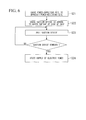
- FIG. 3 is a flowchart showing a first method of supplying electric power to the ship 1 when the ship 1 is moored.
- Step S1 the ship 1 ends navigation and is moored at a predetermined shore. As is shown in FIG. 1 , at this time, the ship 1 collides with a cushioning material 2 provided on a quay and can be thus prevented from directly colliding with the quay.
- Step S2 the power-supplying coil 5 is disposed with respect to the power-receiving coil 7 of the moored ship 1.
- the moving mechanism 17b is disposed or operated to place the power-supplying coil 5 attached to the mobile body 17a of the moving device 17 in the power-supplying device 3 in an opposing position to the power-receiving coil 7 of the ship 1 moored in the Step S1.
- Step S2 It is possible to end the disposition in the Step S2 through the Step S1 by mooring the ship 1 so that the power-receiving coil 7 of the ship 1 opposes to the power-supplying coil 5 provided on the land-side in the Step S1.
- Step S3 electric power is temporarily supplied from the power-supplying coil 5 to the power-receiving coil 7.
- the electric power supplied to the power-supplying coil 5 that is, the measured value P 1 (t) of the electric power
- the electric power supplied to the power-receiving coil 7 that is, the measured value P 2 (t) of the electric power
- the electric power supplied to the power-supplying coil 5 may be measured a plurality of times at different time points so that an average value of the measured values thus obtained may be set to be the measured value P 1 (t) of the electric power to be used in next Step S4.
- the electric power supplied to the power-receiving coil 7 may be measured a plurality of times at different time points so that the average value of the measured values thus obtained may be set to be the measured value P 2 (t) of the electric power to be used in the next Step S4.
- the efficiency ⁇ of the electric power transmission is calculated by the efficiency calculating section 15.
- the efficiency ⁇ of the electric power transmission is calculated by the efficiency calculating section 15 based on the measured value P 1 (t) of the electric power and the measured value P 2 (t) of the electric power which are measured in the Step S3.
- Step S5 it is judged whether the Steps S2, S3 and S4 have been executed a preset plurality of times (preferably 3 times or more) or not. Between these plurality of executions, the position of the power-supplying coil 5 disposed in the Step S2 with respect to the power-receiving coil 7 is varied (for example, approximately by 10 cm or by 20 cm). These positions may be different from each other in a horizontal direction or in a vertical direction or may be scattered in a grid pattern at an interval in the horizontal direction and in the vertical direction. If the judgment in the Step S5 is Yes (that is, the Steps S2, S3 and S4 have been executed a preset plurality of times), the processing proceeds to Step S6.
- Step S5 If the judgment in the Step S5 is No (that is, the Steps S2, S3 and S4 have been executed a smaller number of times than the preset plurality of times), the processing returns to the Step S2. If the ship 1 floats on the sea surface, a position of the ship 1 with respect to the land is not greatly changed by rise and fall of tides in approximately a few minutes or less. Accordingly, the position of the power-supplying coil 5 with respect to the land may be used in place of the position of the power-supplying coil 5 with respect to the power-receiving coil 7.
- the moving device 7 is controlled by the control device 19 to dispose the power-supplying coil 5 in a position where the highest of the calculated efficiencies ⁇ is obtained during a plurality of executions of the Step S4. In this state, the electric power is continuously supplied from the power-supplying coil 5 to the power-receiving coil 7.
- the power-supplying method it is possible to perform the electric power transmission from the power-supplying coil 5 to the power-receiving coil 7 continuously efficiently. Moreover, a precise mark indicative of the position of the power-receiving coil 7 does not need to be provided on the outer surface of side of the ship 1 in order to position the power-supplying coil 5 with respect to the power-receiving coil 7.
- the electromagnetic coupling circuit preferably uses an electromagnetic field resonance system.
- the efficiency of the electric power transmission from the power-supplying coil 5 to the power-receiving coil 7 is not much reduced. Even if the position of the power-supplying coil 5 with respect to the power-receiving coil 7 is changed due to the rocking motion of the ship 1 that is caused by the wave on the sea surface, consequently, it is possible to prevent the electric power transmission efficiency from being reduced. Thus, it is possible to decrease an efficiency fluctuation amount caused by the rocking motion of the wave.
- FIG. 4 is a flowchart showing a second method of supplying electric power to the ship 1 while the ship 1 is moored.
- the electric power is continuously supplied from the power-supplying coil 5 to the power-receiving coil 7 while the ship 1 is moored, and at the same time, Steps S11, S12, S13 and S14, which will be described below, are repeated at a time interval.
- This power-supplying method is performed after the Step S6 explained above, for example.
- Step S11 the position of the power-supplying coil 5 is changed by the control device 19.
- the moving device 17 slightly (for example, approximately by 10 cm) moves the power-supplying coil 5 from the position of the power-supplying coil 5 at the present time to another position.
- the efficiency ⁇ of the electric power transmission from the power-supplying coil 5 to the power-receiving coil 7 is calculated by the efficiency calculating section 15 in a state in which the position of the power-supplying coil 5 is changed in the Step S11. The calculation is carried out by the same method as that in the Step S4.
- Step S13 it is judged whether the number of execution times of the Steps S11 and S12 reaches a preset plurality of times (preferably three times or more) or not. If the judgment is Yes (that is, the Steps S11 and S12 have been executed a preset plurality of times), the processing proceeds to Step S14. If the judgment is No (that is, the number of the execution times of the Steps S11 and S12 is smaller than the preset plurality of times), the processing returns to the Step S11. As an example, it is preferable that a preset number of times should be four and the position of the power-supplying coil 5 should be changed once for each of upward, downward, leftward and rightward directions from the position at the present time in the Step S11.
- the power-supplying coil 5 is disposed, by the control device 19, in the position of the power-supplying coil 5 where the highest of the calculated efficiencies ⁇ is obtained during a plurality of executions of the Step S12.
- the Steps S11, S12, S13 and S14 are executed at a time interval (for example, an interval of one to five minutes). Even if the position of the power-supplying coil 5 with respect to the power-receiving coil 7 is changed to a position where the electric power transmission efficiency is reduced due to the rise and fall of tides or a change in a draft of the ship, accordingly, the position of the power-supplying coil 5 is modified to a position where the electric power transmission efficiency is increased.
- FIG. 5 shows a configuration of a power-supplying device 103 according to a second embodiment of the present invention.
- the power-supplying device 103 supplies electric power to the ship 1 having the power-receiving structure 10.
- FIG. 5 is a view showing the ship 1 seen in a front-rear direction.
- the power-supplying device 103 according to the second embodiment is different from the power-supplying device 3 according to the first embodiment in that the supply power measuring section 11, the receiving section 13, the efficiency calculating section 15, the moving device 17 and the control device 19 are not provided but a support 41 configured to support the power-supplying coil 5 and a suction device 43 attached to the support 41 are provided instead.
- the power-supplying device 103 includes the support 41 configured to support the power-supplying coil 5 and the suction device 43 attached to the support 41.
- the power-supplying coil 5 can adhere to the outer surface of side of the ship 1 in a state in which the power-supplying coil 5 is opposing to the power-receiving coil 7 through the electromagnetic field-transmissive section 9a.
- the suction device 43 is preferably a vacuum cup attached to the support 41.
- the vacuum cup can adhere to the outer surface of side of the ship by sucking internal air through a sucking source (not shown) via a deformable tube 45.
- the sucking source is a vacuum pump, for example.
- An installation area of the suction device 43 is predetermined to be a predetermined area in which the power-supplying coil 5 and the power-receiving coil 7 oppose to each other through the electromagnetic field-transmissive section 9a with the suction device 43 adhering to the outer surface of side of the ship.
- the surface of the outer surface of side of the ship is made smooth so that the suction device 43 (the vacuum cup) can easily adheres and outside of the installation area the surface is made rough so that the suction device 43 is difficult to adhere.
- the adhesion of the suction device 43 is carried out following a procedure of FIG. 6 in the following manner.
- FIG. 6 is a flowchart showing a procedure for starting supply of electric power to the ship 1 moored at a shore.
- Step S21 the position of the power-receiving coil 7 in the ship 1 is roughly known in advance.
- the power-supplying coil 5 is caused to approach the position of the power-receiving coil 7.
- Step S22 next, the suction device 43 is caused to adhere to the outer surface of side of the ship.
- Step S23 the support 41 (that is, the suction device 43) is pulled away from the outer surface of side of the ship in this state.
- Steps S22 and S23 are repeated until the suction device 43 is not removed from the outer surface of side of the ship even if the support 41 is pulled away from the outer surface of side of the ship.
- Step S24 When the suction device 43 is not removed from the outer surface of side of the ship even if the support 41 is pulled away from the outer surface of side of the ship in the Step S23, it is judged that the suction device 43 adheres to the outer surface of side of the ship within the installation area. Therefore, the processing proceeds to Step S24.
- Step S24 supply of electric power from the power-supplying coil 5 to the power-receiving coil 7 is started in the state in which the suction device 43 adheres to the outer surface of side of the ship. Then, the position of the suction device 43 with respect to the shore is varied by the rise and fall of tides or a change in a draft of the ship.
- the tube 45 is deformably flexed to follow the change in the position.
- the power-supplying coil 5 if the suction device 43 is not removed from the outer surface of side of the ship through the Step S23, the power-supplying coil 5 subsequently moves integrally with the ship 1 and the power-receiving coil 7 by the wave on the water surface or the sea surface, for example. Accordingly, the supply of electric power can be performed stably.
- the efficiency of electric power transmission from the power-supplying coil 5 to the power-receiving coil 7 is not much reduced even if the position of the power-supplying coil 5 with respect to the power-receiving coil 7 is shifted. Even if the power-supplying coil 5 is roughly positioned with respect to the power-receiving coil 7, it is possible to prevent the electric power transmission efficiency from being reduced.
- the power-supplying device 103 according to the second embodiment is not provided with the supply power measuring section 11, the receiving section 13, the efficiency calculating section 15, the moving device 17 or the control device 19.
- the other configurations of the power-supplying device 103 according to the second embodiment are the same as those of the power-supplying device 3 according to the first embodiment.
- a rectifier circuit 21 and an inverter 23 may be provided on the support 41 in the power-supplying device 103 according to the second embodiment, they are preferably provided on the side of the external power supply 25 so as to be stationary with respect to the land in the supply of electric power from the power-supplying coil 5 to the power-receiving coil 7.
- an exhaust valve 47 may be provided in the middle of the tube 45 and a rope switch 48 may be provided between the support 41 and a quay as is shown in FIG. 7 .
- the exhaust valve 47 turns ON/OFF an exhaust in accordance with an electrical command given from the rope switch 48. In a normal state, the exhaust valve 47 is set so as not to carry out the exhaust.
- the rope switch 48 includes a switch 48a and a rope 48b.
- the switch 48a is turned ON/OFF depending on whether the rope 48b is stretched or slackened. Consequently, it is possible to electrically detect whether the rope 48b is stretched or slackened.
- a length of the rope 48b is set in such a manner that the rope 48b is slackened during normal power supply and the cable 18 and the tube 45 are not stretched (that is, they are slackened) even when the rope 48b is stretched.
- the ship 1 leaves the quay with the support 41 adhered to due to an unintended motion of the ship 1, a bad weather or the like.
- the rope 48b of the rope switch 48 is stretched so that the switch 48a is flipped. Consequently, an electrical command is given from the rope switch 48 to the exhaust valve 47 ordering to perform the exhaust.
- the exhaust is performed through the exhaust valve 47, the vacuum state of the tube 45 is released.
- the adhesion of the suction device 43 attached to the support 41 to the outer surface of side of the ship 1 is terminated and the support 41 leaves the ship 1. Therefore, it is possible to prevent the cable 18 or the tube 45 from being broken. It is more preferable to stop an operation of the sucking source (the vacuum pump) simultaneously with the exhaust from the exhaust valve 47.
- the power-supplying device 3 according to the first embodiment or the power-supplying device 103 according to the second embodiment may be provided with a billing device (not shown).
- a billing device (not shown).
- the mobile body 17a is moved in such a manner that the power-supplying coil 5 goes away from the power-receiving coil 7 in the first embodiment or the suction device 43 stops the adhesion to the outer surface of side of the ship and is thus removed from the outer surface of side of the ship in the second embodiment, for example.
- the exhaust valve 47 is provided in the middle of the tube 45, it is also possible to give an electrical command to the exhaust valve 47 in order to perform the exhaust, thereby removing the suction device 43 from the outer surface of side of the ship.
- the power-receiving coil is provided on the inside of the outer wall surface-forming section of the ship and the electromagnetic field-transmissive section formed of a material through which an electromagnetic field propagates is provided in the opposing portion to the power-receiving coil in the outer wall surface-forming section.
- the power-receiving coil is not protruded from the outer surface of side of the ship but can wirelessly receive electric power from the power-supplying coil on the land-side through the electromagnetic field-transmissive section.
- the power-receiving coil does not disturb the navigation of the ship and is not required to be pulled into the ship after the supply of the electric power to the ship is finished.
Landscapes
- Engineering & Computer Science (AREA)
- Power Engineering (AREA)
- Mechanical Engineering (AREA)
- Computer Networks & Wireless Communication (AREA)
- Transportation (AREA)
- Chemical & Material Sciences (AREA)
- Combustion & Propulsion (AREA)
- Ocean & Marine Engineering (AREA)
- Charge And Discharge Circuits For Batteries Or The Like (AREA)
Priority Applications (1)
| Application Number | Priority Date | Filing Date | Title |
|---|---|---|---|
| EP16193462.5A EP3138768B1 (fr) | 2012-04-13 | 2013-04-10 | Structure de reception de puissance de navire, dispositif d'alimentation en energie pour navire et procede d'alimentation en energie pour navire |
Applications Claiming Priority (2)
| Application Number | Priority Date | Filing Date | Title |
|---|---|---|---|
| JP2012092176 | 2012-04-13 | ||
| PCT/JP2013/060820 WO2013154131A1 (fr) | 2012-04-13 | 2013-04-10 | Structure de réception d'énergie pour navire, dispositif d'alimentation électrique et procédé d'alimentation électrique |
Related Child Applications (1)
| Application Number | Title | Priority Date | Filing Date |
|---|---|---|---|
| EP16193462.5A Division EP3138768B1 (fr) | 2012-04-13 | 2013-04-10 | Structure de reception de puissance de navire, dispositif d'alimentation en energie pour navire et procede d'alimentation en energie pour navire |
Publications (2)
| Publication Number | Publication Date |
|---|---|
| EP2838178A1 true EP2838178A1 (fr) | 2015-02-18 |
| EP2838178A4 EP2838178A4 (fr) | 2016-05-04 |
Family
ID=49327690
Family Applications (2)
| Application Number | Title | Priority Date | Filing Date |
|---|---|---|---|
| EP13775110.3A Withdrawn EP2838178A4 (fr) | 2012-04-13 | 2013-04-10 | Structure de réception d'énergie pour navire, dispositif d'alimentation électrique et procédé d'alimentation électrique |
| EP16193462.5A Active EP3138768B1 (fr) | 2012-04-13 | 2013-04-10 | Structure de reception de puissance de navire, dispositif d'alimentation en energie pour navire et procede d'alimentation en energie pour navire |
Family Applications After (1)
| Application Number | Title | Priority Date | Filing Date |
|---|---|---|---|
| EP16193462.5A Active EP3138768B1 (fr) | 2012-04-13 | 2013-04-10 | Structure de reception de puissance de navire, dispositif d'alimentation en energie pour navire et procede d'alimentation en energie pour navire |
Country Status (5)
| Country | Link |
|---|---|
| US (1) | US9742202B2 (fr) |
| EP (2) | EP2838178A4 (fr) |
| JP (1) | JP5828358B2 (fr) |
| CN (1) | CN104221252B (fr) |
| WO (1) | WO2013154131A1 (fr) |
Families Citing this family (17)
| Publication number | Priority date | Publication date | Assignee | Title |
|---|---|---|---|---|
| WO2016121089A1 (fr) * | 2015-01-30 | 2016-08-04 | 中国電力株式会社 | Système et procédé d'alimentation électrique |
| JP2016163494A (ja) * | 2015-03-04 | 2016-09-05 | ヤンマー株式会社 | 船舶の電力供給システム |
| FI126893B (en) * | 2016-01-25 | 2017-07-31 | Abb Schweiz Ag | Power supply to the vessel |
| DK201670190A1 (en) * | 2016-03-31 | 2017-10-09 | A P Møller - Mærsk As | Boat with connection to shore |
| CN106487063A (zh) * | 2016-11-07 | 2017-03-08 | 武汉理工大学 | 基于微网储能的纯电动船舶的无线充电装置和方法 |
| CN107826222B (zh) * | 2017-10-17 | 2020-04-07 | 南通大学 | 一种无人巡航船自动安全无线充电系统 |
| CN107769345A (zh) * | 2017-12-08 | 2018-03-06 | 武汉理工大学 | 一种电动游艇无线充电装置 |
| CN107947379B (zh) * | 2017-12-20 | 2023-08-01 | 温州正泰船岸电气有限公司 | 无线连接的船舶岸电系统 |
| CN107826223A (zh) * | 2018-01-30 | 2018-03-23 | 南通大学 | 一种浮动式带无线充电功能的智能船坞装置 |
| CN108417370B (zh) * | 2018-03-21 | 2019-02-26 | 北京市燃气集团有限责任公司 | 用于燃气管道自动力检测机器人的充电系统及充电方法 |
| GB2579566A (en) * | 2018-12-03 | 2020-07-01 | Bombardier Primove Gmbh | Power transfer device and mooring area for inductively charging a water-bound vehicle |
| GB2579565A (en) * | 2018-12-03 | 2020-07-01 | Bombardier Primove Gmbh | Inductive power transfer device and system for inductively charging a water-bound vehicle and method for operating an inductive power transfer device |
| DE102020113744A1 (de) | 2020-05-20 | 2021-11-25 | Ipt Technology Gmbh | Vorrichtung und Verfahren zur induktiven Übertragung elektrischer Energie zu einem Wasserfahrzeug und Ladesystem |
| US12191673B2 (en) | 2020-12-03 | 2025-01-07 | C-Innovation, LLC | Marine vessel with repositionable onboard inductive charge system for recharging an onboard rechargeable energy source when servicing offshore wind turbines |
| EP4281309A4 (fr) * | 2021-01-20 | 2025-01-15 | Lee, Sze Min George | Système de charge électrique pour navires marins |
| WO2024185606A1 (fr) * | 2023-03-08 | 2024-09-12 | 株式会社デンソー | Unité de bobine |
| JP7816390B2 (ja) * | 2023-03-08 | 2026-02-18 | 株式会社デンソー | コイルユニット |
Family Cites Families (23)
| Publication number | Priority date | Publication date | Assignee | Title |
|---|---|---|---|---|
| JPH1028332A (ja) * | 1996-07-11 | 1998-01-27 | Sumitomo Wiring Syst Ltd | 電気自動車用充電装置 |
| JP2004194444A (ja) * | 2002-12-12 | 2004-07-08 | Noritz Corp | 電源装置 |
| JP4442517B2 (ja) * | 2005-06-07 | 2010-03-31 | パナソニック電工株式会社 | 非接触給電装置及び自律移動装置用給電システム |
| JP4604094B2 (ja) * | 2008-01-23 | 2010-12-22 | トヨタ自動車株式会社 | 車両用給電装置および車両用窓材 |
| JP5334470B2 (ja) * | 2008-06-30 | 2013-11-06 | 三井造船株式会社 | 非接触式の船舶用給電システム、船舶及び船舶への給電方法 |
| WO2010036980A1 (fr) * | 2008-09-27 | 2010-04-01 | Witricity Corporation | Systèmes de transfert d'énergie sans fil |
| US8723366B2 (en) * | 2008-09-27 | 2014-05-13 | Witricity Corporation | Wireless energy transfer resonator enclosures |
| KR101248453B1 (ko) * | 2008-12-09 | 2013-04-01 | 도요타지도샤가부시키가이샤 | 비접촉 전력 전송 장치 및 비접촉 전력 전송 장치에 있어서의 전력 전송 방법 |
| JP5285418B2 (ja) * | 2008-12-24 | 2013-09-11 | 株式会社豊田自動織機 | 共鳴型非接触電力供給装置 |
| JP2010183814A (ja) * | 2009-02-09 | 2010-08-19 | Toyota Industries Corp | 非接触電力伝送装置 |
| US9186995B2 (en) * | 2009-05-14 | 2015-11-17 | Toyota Jidosha Kabushiki Kaisha | Non-contact power receiving apparatus and vehicle having the same |
| RU2506181C2 (ru) * | 2009-07-15 | 2014-02-10 | Кондуктикс-Вампфлер Гмбх | Система для индуктивной зарядки транспортных средств, снабженных электронной системой позиционирования |
| RU2523708C2 (ru) * | 2009-08-19 | 2014-07-20 | Конинклейке Филипс Электроникс Н.В. | Электронное устройство и чашечная присоска, пригодная для такого электронного устройства |
| JP2011188733A (ja) * | 2010-02-12 | 2011-09-22 | Semiconductor Energy Lab Co Ltd | 移動体、無線給電システムおよび無線給電方法 |
| WO2011114527A1 (fr) * | 2010-03-19 | 2011-09-22 | 富士通株式会社 | Téléphone mobile |
| JP5595098B2 (ja) * | 2010-04-16 | 2014-09-24 | 三菱重工鉄構エンジニアリング株式会社 | 電力伝送装置 |
| US20110309689A1 (en) * | 2010-06-17 | 2011-12-22 | Semiconductor Energy Laboratory Co., Ltd. | Electric power transmitting device, electric power receiving device, and power supply method using electric power transmitting and receiving devices |
| JP5348183B2 (ja) * | 2010-08-18 | 2013-11-20 | 三洋電機株式会社 | 電池内蔵機器と充電装置 |
| EP2722216B1 (fr) * | 2011-06-20 | 2019-01-16 | Toyota Jidosha Kabushiki Kaisha | Dispositif de réception d'énergie sans contact, dispositif d'émission d'énergie sans contact et système de réception et d'émission d'énergie sans contact |
| US20140111021A1 (en) * | 2011-06-30 | 2014-04-24 | Toyota Jidosha Kabushiki Kaisha | Power transmission device, power reception device and power transfer system |
| CN202152117U (zh) * | 2011-07-22 | 2012-02-29 | 佛山市海天调味食品股份有限公司 | 一种真空吸附装置 |
| US20150326028A1 (en) * | 2011-09-21 | 2015-11-12 | Pioneer Corporation | Wireless power transmitting apparatus, wireless power receiving apparatus, and wireless power feeding system |
| US8928182B2 (en) * | 2011-12-16 | 2015-01-06 | Tdk Corporation | Wireless power feeder and wireless power transmission system |
-
2013
- 2013-04-10 EP EP13775110.3A patent/EP2838178A4/fr not_active Withdrawn
- 2013-04-10 CN CN201380018821.1A patent/CN104221252B/zh active Active
- 2013-04-10 JP JP2014510185A patent/JP5828358B2/ja active Active
- 2013-04-10 EP EP16193462.5A patent/EP3138768B1/fr active Active
- 2013-04-10 WO PCT/JP2013/060820 patent/WO2013154131A1/fr not_active Ceased
-
2014
- 2014-09-11 US US14/483,370 patent/US9742202B2/en active Active
Also Published As
| Publication number | Publication date |
|---|---|
| EP2838178A4 (fr) | 2016-05-04 |
| EP3138768A3 (fr) | 2017-06-21 |
| CN104221252A (zh) | 2014-12-17 |
| US20140375140A1 (en) | 2014-12-25 |
| WO2013154131A1 (fr) | 2013-10-17 |
| JPWO2013154131A1 (ja) | 2015-12-17 |
| EP3138768A2 (fr) | 2017-03-08 |
| EP3138768B1 (fr) | 2020-12-30 |
| US9742202B2 (en) | 2017-08-22 |
| JP5828358B2 (ja) | 2015-12-02 |
| CN104221252B (zh) | 2017-06-23 |
Similar Documents
| Publication | Publication Date | Title |
|---|---|---|
| EP3138768B1 (fr) | Structure de reception de puissance de navire, dispositif d'alimentation en energie pour navire et procede d'alimentation en energie pour navire | |
| CN105966578B (zh) | 输电装置及受电装置 | |
| EP2838174B1 (fr) | Unité d'alimentation en énergie sous l'eau | |
| US9270138B2 (en) | Electric power transmission system | |
| EP2879267B1 (fr) | Système d'alimentation en énergie sans contact | |
| JP2013017254A (ja) | 電力伝送システム | |
| CN105379063A (zh) | 非接触供电系统 | |
| EP2833509A1 (fr) | Système de transmission électrique | |
| JP2013183496A (ja) | 電力伝送システム | |
| JP2010183814A (ja) | 非接触電力伝送装置 | |
| JP2013005593A (ja) | 給電装置及び給電システム | |
| KR20130141703A (ko) | 토크 제어 장치 및 비접촉 충전 시스템 | |
| CN104904096B (zh) | 非接触供电系统 | |
| EP2693600A1 (fr) | Système de transmission de puissance | |
| JP2013158188A (ja) | 電力伝送システム | |
| JP6897371B2 (ja) | 車両および電力伝送システム | |
| JP2013211933A (ja) | 電力伝送システム | |
| JP2013132141A (ja) | 電力伝送システム | |
| JP7582851B2 (ja) | 受電装置、送電電圧制御方法および水中給電システム | |
| JP2020127269A (ja) | 受電機器 | |
| KR101271131B1 (ko) | 히팅 시스템 및 히팅 시스템을 포함하는 선박 | |
| JP7117219B2 (ja) | 無線給電装置およびこれを用いた多軸ロボット | |
| JP2013021822A (ja) | アンテナ |
Legal Events
| Date | Code | Title | Description |
|---|---|---|---|
| PUAI | Public reference made under article 153(3) epc to a published international application that has entered the european phase |
Free format text: ORIGINAL CODE: 0009012 |
|
| 17P | Request for examination filed |
Effective date: 20140925 |
|
| AK | Designated contracting states |
Kind code of ref document: A1 Designated state(s): AL AT BE BG CH CY CZ DE DK EE ES FI FR GB GR HR HU IE IS IT LI LT LU LV MC MK MT NL NO PL PT RO RS SE SI SK SM TR |
|
| AX | Request for extension of the european patent |
Extension state: BA ME |
|
| DAX | Request for extension of the european patent (deleted) | ||
| RIC1 | Information provided on ipc code assigned before grant |
Ipc: H02J 17/00 00000000AFI20151209BHEP Ipc: H02J 7/00 20060101ALI20151209BHEP Ipc: B63J 99/00 20090101ALI20151209BHEP |
|
| RA4 | Supplementary search report drawn up and despatched (corrected) |
Effective date: 20160405 |
|
| RIC1 | Information provided on ipc code assigned before grant |
Ipc: B63J 99/00 20090101ALI20160401BHEP Ipc: H02J 50/00 20160101AFI20160401BHEP Ipc: H02J 7/00 20060101ALI20160401BHEP |
|
| STAA | Information on the status of an ep patent application or granted ep patent |
Free format text: STATUS: THE APPLICATION IS DEEMED TO BE WITHDRAWN |
|
| 18D | Application deemed to be withdrawn |
Effective date: 20161103 |