EP2839926A2 - Dispositif d'aiguisage de couteaux de coupe-racines - Google Patents
Dispositif d'aiguisage de couteaux de coupe-racines Download PDFInfo
- Publication number
- EP2839926A2 EP2839926A2 EP14401065.9A EP14401065A EP2839926A2 EP 2839926 A2 EP2839926 A2 EP 2839926A2 EP 14401065 A EP14401065 A EP 14401065A EP 2839926 A2 EP2839926 A2 EP 2839926A2
- Authority
- EP
- European Patent Office
- Prior art keywords
- centering
- unit
- cutting element
- centering unit
- pliers
- Prior art date
- Legal status (The legal status is an assumption and is not a legal conclusion. Google has not performed a legal analysis and makes no representation as to the accuracy of the status listed.)
- Granted
Links
Images




Classifications
-
- B—PERFORMING OPERATIONS; TRANSPORTING
- B23—MACHINE TOOLS; METAL-WORKING NOT OTHERWISE PROVIDED FOR
- B23C—MILLING
- B23C3/00—Milling particular work; Special milling operations; Machines therefor
- B23C3/12—Trimming or finishing edges, e.g. deburring welded corners
-
- A—HUMAN NECESSITIES
- A01—AGRICULTURE; FORESTRY; ANIMAL HUSBANDRY; HUNTING; TRAPPING; FISHING
- A01F—PROCESSING OF HARVESTED PRODUCE; HAY OR STRAW PRESSES; DEVICES FOR STORING AGRICULTURAL OR HORTICULTURAL PRODUCE
- A01F29/00—Cutting apparatus specially adapted for cutting hay, straw or the like
- A01F29/09—Details
- A01F29/22—Arrangement of knife sharpening devices
-
- B—PERFORMING OPERATIONS; TRANSPORTING
- B23—MACHINE TOOLS; METAL-WORKING NOT OTHERWISE PROVIDED FOR
- B23C—MILLING
- B23C3/00—Milling particular work; Special milling operations; Machines therefor
-
- B—PERFORMING OPERATIONS; TRANSPORTING
- B23—MACHINE TOOLS; METAL-WORKING NOT OTHERWISE PROVIDED FOR
- B23C—MILLING
- B23C7/00—Milling devices able to be attached to a machine tool, whether or not replacing an operative portion of the machine tool
-
- B—PERFORMING OPERATIONS; TRANSPORTING
- B23—MACHINE TOOLS; METAL-WORKING NOT OTHERWISE PROVIDED FOR
- B23Q—DETAILS, COMPONENTS, OR ACCESSORIES FOR MACHINE TOOLS, e.g. ARRANGEMENTS FOR COPYING OR CONTROLLING; MACHINE TOOLS IN GENERAL CHARACTERISED BY THE CONSTRUCTION OF PARTICULAR DETAILS OR COMPONENTS; COMBINATIONS OR ASSOCIATIONS OF METAL-WORKING MACHINES, NOT DIRECTED TO A PARTICULAR RESULT
- B23Q16/00—Equipment for precise positioning of tool or work into particular locations not otherwise provided for
-
- B—PERFORMING OPERATIONS; TRANSPORTING
- B24—GRINDING; POLISHING
- B24B—MACHINES, DEVICES, OR PROCESSES FOR GRINDING OR POLISHING; DRESSING OR CONDITIONING OF ABRADING SURFACES; FEEDING OF GRINDING, POLISHING, OR LAPPING AGENTS
- B24B3/00—Sharpening cutting edges, e.g. of tools; Accessories therefor, e.g. for holding the tools
- B24B3/58—Sharpening cutting edges, e.g. of tools; Accessories therefor, e.g. for holding the tools of tools having scalloped cutting edges
- B24B3/586—Sharpening cutting edges, e.g. of tools; Accessories therefor, e.g. for holding the tools of tools having scalloped cutting edges of serrated edges, e.g. triangular shaped
-
- C—CHEMISTRY; METALLURGY
- C13—SUGAR INDUSTRY
- C13B—PRODUCTION OF SUCROSE; APPARATUS SPECIALLY ADAPTED THEREFOR
- C13B5/00—Reducing the size of material from which sugar is to be extracted
- C13B5/08—Knives; Adjustment or maintenance thereof
-
- B—PERFORMING OPERATIONS; TRANSPORTING
- B23—MACHINE TOOLS; METAL-WORKING NOT OTHERWISE PROVIDED FOR
- B23C—MILLING
- B23C2215/00—Details of workpieces
-
- B—PERFORMING OPERATIONS; TRANSPORTING
- B23—MACHINE TOOLS; METAL-WORKING NOT OTHERWISE PROVIDED FOR
- B23C—MILLING
- B23C2220/00—Details of milling processes
- B23C2220/48—Methods of milling not otherwise provided for
-
- B—PERFORMING OPERATIONS; TRANSPORTING
- B23—MACHINE TOOLS; METAL-WORKING NOT OTHERWISE PROVIDED FOR
- B23C—MILLING
- B23C2270/00—Details of milling machines, milling processes or milling tools not otherwise provided for
- B23C2270/20—Milling external areas of components
-
- B—PERFORMING OPERATIONS; TRANSPORTING
- B23—MACHINE TOOLS; METAL-WORKING NOT OTHERWISE PROVIDED FOR
- B23Q—DETAILS, COMPONENTS, OR ACCESSORIES FOR MACHINE TOOLS, e.g. ARRANGEMENTS FOR COPYING OR CONTROLLING; MACHINE TOOLS IN GENERAL CHARACTERISED BY THE CONSTRUCTION OF PARTICULAR DETAILS OR COMPONENTS; COMBINATIONS OR ASSOCIATIONS OF METAL-WORKING MACHINES, NOT DIRECTED TO A PARTICULAR RESULT
- B23Q15/00—Automatic control or regulation of feed movement, cutting velocity or position of tool or work
- B23Q15/007—Automatic control or regulation of feed movement, cutting velocity or position of tool or work while the tool acts upon the workpiece
- B23Q15/14—Control or regulation of the orientation of the tool with respect to the work
-
- B—PERFORMING OPERATIONS; TRANSPORTING
- B23—MACHINE TOOLS; METAL-WORKING NOT OTHERWISE PROVIDED FOR
- B23Q—DETAILS, COMPONENTS, OR ACCESSORIES FOR MACHINE TOOLS, e.g. ARRANGEMENTS FOR COPYING OR CONTROLLING; MACHINE TOOLS IN GENERAL CHARACTERISED BY THE CONSTRUCTION OF PARTICULAR DETAILS OR COMPONENTS; COMBINATIONS OR ASSOCIATIONS OF METAL-WORKING MACHINES, NOT DIRECTED TO A PARTICULAR RESULT
- B23Q17/00—Arrangements for observing, indicating or measuring on machine tools
- B23Q17/22—Arrangements for observing, indicating or measuring on machine tools for indicating or measuring existing or desired position of tool or work
-
- B—PERFORMING OPERATIONS; TRANSPORTING
- B24—GRINDING; POLISHING
- B24B—MACHINES, DEVICES, OR PROCESSES FOR GRINDING OR POLISHING; DRESSING OR CONDITIONING OF ABRADING SURFACES; FEEDING OF GRINDING, POLISHING, OR LAPPING AGENTS
- B24B3/00—Sharpening cutting edges, e.g. of tools; Accessories therefor, e.g. for holding the tools
- B24B3/58—Sharpening cutting edges, e.g. of tools; Accessories therefor, e.g. for holding the tools of tools having scalloped cutting edges
-
- Y—GENERAL TAGGING OF NEW TECHNOLOGICAL DEVELOPMENTS; GENERAL TAGGING OF CROSS-SECTIONAL TECHNOLOGIES SPANNING OVER SEVERAL SECTIONS OF THE IPC; TECHNICAL SUBJECTS COVERED BY FORMER USPC CROSS-REFERENCE ART COLLECTIONS [XRACs] AND DIGESTS
- Y10—TECHNICAL SUBJECTS COVERED BY FORMER USPC
- Y10T—TECHNICAL SUBJECTS COVERED BY FORMER US CLASSIFICATION
- Y10T409/00—Gear cutting, milling, or planing
- Y10T409/30—Milling
- Y10T409/30084—Milling with regulation of operation by templet, card, or other replaceable information supply
- Y10T409/300896—Milling with regulation of operation by templet, card, or other replaceable information supply with sensing of numerical information and regulation without mechanical connection between sensing means and regulated means [i.e., numerical control]
-
- Y—GENERAL TAGGING OF NEW TECHNOLOGICAL DEVELOPMENTS; GENERAL TAGGING OF CROSS-SECTIONAL TECHNOLOGIES SPANNING OVER SEVERAL SECTIONS OF THE IPC; TECHNICAL SUBJECTS COVERED BY FORMER USPC CROSS-REFERENCE ART COLLECTIONS [XRACs] AND DIGESTS
- Y10—TECHNICAL SUBJECTS COVERED BY FORMER USPC
- Y10T—TECHNICAL SUBJECTS COVERED BY FORMER US CLASSIFICATION
- Y10T409/00—Gear cutting, milling, or planing
- Y10T409/30—Milling
- Y10T409/303752—Process
- Y10T409/303808—Process including infeeding
-
- Y—GENERAL TAGGING OF NEW TECHNOLOGICAL DEVELOPMENTS; GENERAL TAGGING OF CROSS-SECTIONAL TECHNOLOGIES SPANNING OVER SEVERAL SECTIONS OF THE IPC; TECHNICAL SUBJECTS COVERED BY FORMER USPC CROSS-REFERENCE ART COLLECTIONS [XRACs] AND DIGESTS
- Y10—TECHNICAL SUBJECTS COVERED BY FORMER USPC
- Y10T—TECHNICAL SUBJECTS COVERED BY FORMER US CLASSIFICATION
- Y10T409/00—Gear cutting, milling, or planing
- Y10T409/30—Milling
- Y10T409/306216—Randomly manipulated, work supported, or work following device
- Y10T409/306384—Randomly manipulated, work supported, or work following device with work supported guide means
Definitions
- the invention relates to a device for sharpening Schnitzelmessern for Erdfruchsschnitzelmaschinen.
- Schnitzelmesser are many times in use, especially for the production of beet pulp with appropriate Schnitzelmaschinen. Such Schnitzelmesser be used in multiple forms and are often dull due to the intended use, so a resharpening of the knife is required.
- Such knives consist of a knife body, on which one side saddle-shaped cutting elements are formed, which are arranged side by side in a plurality. For sharpening the Schnitzelmesser must be sharpened at each edge of the pitched roof-shaped cutting elements.
- the present invention seeks to provide a device of the generic type, which allows the sharpening of Schnitzelmessern in virtually fully automatic manner, without the need for a large manual effort.
- the device consists essentially of a in the direction of a Y-axis towards and away from each other mechanically linearly adjustable centering unit for centering and positioning of the cutting blade relative to a disc milling cutter, a processing unit with a mechanically rotatable disc milling cutter with roof-like milling edge, by means of which the positioned Schnitzelmesser their cutting edges can be sharpened one after the other, with the centering unit and the processing unit being held on a device frame so that they can be adjusted by a motor.
- a pair of pliers which fixes the knife body of a cutting knife in a clamping position and which is mechanically adjustable on a frame-fixed guide, that is to say preferably electromotively, in an X-direction.
- the centering unit and the processing unit are moved away from each other, so that the positioning of the Schnitzelmessers is made possible by the pliers.
- the pliers are adjusted with the cutting knife in the X direction until a first pitched roof-like cutting element is correctly aligned with the milling edge of the side milling cutter.
- the centering unit is adjusted with a centering piece and / or the processing unit with the side milling cutter in a working position in which the centering unit is placed with the centering on the back of the gable roof-like cutting element and engages the processing unit with the milling edge of the disc cutter in the front of the gable roof-like cutting element ,
- the disc milling cutter is moved in the direction of the centering unit, that is to say in the Y direction by a predetermined milling distance, so that the corresponding cutting element of the cutting blade is sharpened.
- the elements are moved to an end position, in which again the centering unit and the processing unit are moved away from each other, in a position corresponding to the starting position.
- the pliers can be adjusted with the cutting blade to a division of the cutting blade in the X direction, in which position a following on the first saddle-like cutting element cutting element for centering and Disc milling cutter is aligned in preparation for the next milling process.
- the other positions are again in the same sequence, as previously stated. This procedure is done until all cutting elements are processed.
- the Schnitzelmesser can be removed from the pliers and another sharpened Schnitzelmesser be inserted into the pliers, the device is operated in the manner specified as intended to sharpen this knife.
- the device is equipped with an electronic processor having a memory for storing setpoints, a comparator for comparing setpoints with actual values, and a controller for controlling the mechanical, pneumatic and / or electric drive means for movement the centering unit, the processing unit, the disc cutter and the pliers.
- All elements of the device can be actuated by an electronic controller, with an electronic processor controlling the adjustment and commissioning of the respective units.
- the processor has a memory for storing desired values on the position and penetration depth of the milling cutter, as well as a comparator for comparing setpoints with actual values and a controller for controlling the mechanical, pneumatic and / or electric drive means by which the centering unit, the processing unit, the Disc milling cutter and the pliers are moved and put into operation.
- the centering of the centering unit is limited adjustable from a spring-mounted center position in a deflected against the spring force adjustment position in the X direction, wherein for detecting the adjustment an electrical measuring means is arranged and with an electronic control and / or a electronic memory is coupled.
- this data stored in the control can then be an adjustment of the pliers and the cutting blade in the X direction in the exact target position, so that subsequently the exact milling process can be performed because the cutter is then aligned exactly to the roof-like cutting element.
- the centering is in the middle position, which is detected by the electrical measuring means and detected as a target position.
- the centering of the centering unit is placed directly in an adjustment position on the milling edge of the side milling cutter, detected a possible movement of the centering piece from the center position weg réelle in an adjustment position and the thus determined position of the disc cutter is stored in an electronic memory, said this position so that the exact working position of the side milling cutter and is stored in the memory and as a setpoint.
- the centering piece is seated in the working position on the back of the pitched roof-like, to be machined cutting element, wherein a possible deviation of the position in the X direction of the target position wegmix is detected and the electronic control a control signal from the Deviation is derived, by means of which the pliers drive is turned on in the X direction and the pliers is moved to the desired position.
- the centering unit is adjustable by means of an electrical actuating means in the Y direction, wherein the electrical adjusting means is coupled to a current increase circuit, by means of which the adjusting means is switched off when a current is exceeded, when the centering unit against a fixed obstacle in particular against the Disc milling or pressed against the back of the pitched roof-like cutting element.
- a preferred method for operating a device described above is seen in that in the working position, the centering unit is moved with the centering against the back of the cutting element to be processed until a current increase detected and thereby the feed of the centering unit is terminated, the distance covered by the centering over an electronic encoder of the actuator to the Control is transmitted, the detected measured value is compared with the stored in the memory measurement of the zero position of the disc cutter and from the control value for adjusting the disc cutter in the direction of the front side of the cutting element is derived and the milling depth of the disc cutter is determined.
- a cutting knife 1 is shown, which is held by a pair of pliers 8, which biases the knife body 9. Furthermore, a centering unit 4 is arranged and a processing unit 5, both of which are movable in the direction of the arrow 3, ie in the Y direction and in the opposite direction. Furthermore, a side milling cutter 6 is provided on the processing unit 5. Essential frame-fixed parts are fixed to an only hinted drawn device frame 7.
- the cutting blade 1 has a plurality of mutually parallel, aligned in the Y direction 3 pitched roof-like cutting elements which extend over part of the width of the cutting blade 1, ie in the view, for example according to Figure 1A from top to bottom and those at their in Figure 1A downwardly facing ends form the sharpened cutting edges.
- the pliers 8 is adjustable on a guide 10 in the direction of the arrow 2 in the X direction, by means of a drive element in the form of a servomotor 11.
- the centering unit 4 has a centering piece 12, which is mounted transversely to the adjustment direction Y in the direction of the movement arrow 14 resiliently. Between fixed components of the centering unit 4 and the movable centering piece 12, measuring means 13 are preferably arranged in the form of inductive displacement transducers, by means of which the travel can be detected and processed electronically.
- the operation of the device is as follows.
- FIG. 1A-C For example, a situation is shown in which the zero position of the milling cutter 6 is detected, which can be stored in the data processing of the device as a setpoint to be used for further processing.
- the processing unit 5 moves in the negative Y direction 3 to a predetermined position.
- the centering unit 4 moves in the positive Y direction with the centering piece 12 against the stationary cutter 6.
- the path that the centering piece 12 moves until it comes into contact with the milling cutter 6 is transmitted via an encoder of the positioning motor 15 to the electronic control.
- the displacement of the transversely to the Y direction resiliently held centering piece 12 is detected by the measuring means 13, in particular an inductive position transducer and transmitted as an electrical signal to the controller.
- the exact position and also the exact diameter of the cutter 6 is detected and stored in the controller as an actual value. This is important for detecting the wear of the milling cutter 6.
- the detection of the zero position is performed after each cutter change and after changing the operating parameters of the centering unit 4.
- FIGs 2A-2D is shown an operating situation in which the centering unit 4 and the processing unit 5 are moved away from each other, in a starting position, so that then the clamped by means of the pliers 8 Schnitzelmesser 1 of this pliers 8 in the processing position can be moved.
- This position is specified with a tolerance of plus / minus 1.5 mm. For processing, however, a tolerance of plus / minus 0.05 mm is required.
- This position is detected in step three, which is in Figure 3A-3E is explained.
- the centering unit 4 moves in the positive Y direction with the centering piece 12 in the notch of the cutting blade 1.
- the corresponding roof shape of the centering piece 12 is, for example, in Figure 1C seen.
- the saddle-roof-like design of the cutting element of the cutting blade 1 corresponds to this roof shape.
- the centering piece 12 shifts in deviation from the target position in the X direction.
- This shift is recorded by the measuring means 13, thus in particular the inductive displacement transducer and transmitted as a control signal to the controller.
- this position is compared with the zero position of the milling cutter 6.
- a control signal is transmitted to the servomotor 11 of the forceps 8, and the actuator then makes the corresponding correction in the X direction by correspondingly accurate adjustment of the forceps 8.
- the scraper blade 1 is moved in the X direction exact machining position.
- the centering unit 4 moves the centering piece 12 into the corresponding roof shape of the chip knife 1 until a current increase is detected by the electronic control and a power cut occurs. As soon as during the propulsion of the centering unit 4 in the direction of arrow Y, a position is reached at which the current for adjusting the servomotor 15 detects a strong increase in current, the centering unit stops 4. The distance traveled is transmitted via a transmitter of the servomotor 15 to the controller. This is compared with the zero position of the milling cutter 6 and serves the machining unit 5 as a measured value for the depth of the milling.
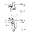
- FIGS. 4A to 4E the step is shown in which the milling takes place.
- the depth of the milling is detected and calculated by the controller as a function of the desired wall thickness of the chip knife and the path of the centering unit 4 measured in step 3.
- the centering unit 4 can remain as a knife support in the position on the cutting blade 1. This function can also be switched off, depending on the stability of the system.
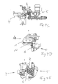
- FIG. 5A-5E another step is shown.
- the centering unit 4 and the processing unit 5 move into the basic position, that is, away from one another, and the forceps 8 moves with the chopper blade 1 by a division of the chopper blade in the positive X direction continue, so that the next saddle-shaped cutting element to the side milling cutter 6 is at least anticipated.
- the further alignment and processing takes place according to the steps three to five described above. This is done in succession in time until all saddle-shaped cutting elements of the cutting blade 1 are processed.
- the finished cutting blade 1 is transferred by means of the pliers 8 to further processing or storage positions.
- a Pfeilfräsung can be made with the same procedure.
- FIGS. 4A to 4E the disc cutter 6 are put into operation to sharpen the corresponding saddle-like cutting element of the cutting blade 1.
- the milling process takes place up to the predetermined milling depth.
- Figure 4D It is shown that the centering piece 12 is still the back of the pitched roof-like cutting element of the cutting blade 1 rests and in Figure 4E is the movement of the disc cutter 6 in the direction of the centering unit 4 illustrated with a movement arrow.
- FIG. 5A-5E is shown that the centering unit 4 and the processing unit 5 are returned to the initial position, so that the pliers 8 can be moved by means of the servomotor 11 by a measuring division further in the X direction, and then perform the procedure described above again.
- FIG. 5D It is shown that both the centering piece 12 and the disc milling cutter 6 are moved away from the corresponding saddle-type cutting element, so that the cutting blade 1 of these elements is free.
- the movement arrows are in FIG. 5E seen.
Landscapes
- Engineering & Computer Science (AREA)
- Mechanical Engineering (AREA)
- Chemical & Material Sciences (AREA)
- Life Sciences & Earth Sciences (AREA)
- Biochemistry (AREA)
- Organic Chemistry (AREA)
- Environmental Sciences (AREA)
- Apparatuses For Bulk Treatment Of Fruits And Vegetables And Apparatuses For Preparing Feeds (AREA)
- Harvesting Machines For Root Crops (AREA)
- Milling Processes (AREA)
- Processing Of Stones Or Stones Resemblance Materials (AREA)
- Automatic Tool Replacement In Machine Tools (AREA)
Priority Applications (1)
| Application Number | Priority Date | Filing Date | Title |
|---|---|---|---|
| PL14401065T PL2839926T3 (pl) | 2013-06-26 | 2014-05-27 | Urządzenie do ostrzenia noży do krajanki |
Applications Claiming Priority (1)
| Application Number | Priority Date | Filing Date | Title |
|---|---|---|---|
| DE102013106659.3A DE102013106659B3 (de) | 2013-06-26 | 2013-06-26 | Vorrichtung zum Schärfen von Schnitzelmessern und Verfahren zum Betrieb dieser Vorrichtung |
Publications (3)
| Publication Number | Publication Date |
|---|---|
| EP2839926A2 true EP2839926A2 (fr) | 2015-02-25 |
| EP2839926A3 EP2839926A3 (fr) | 2015-09-30 |
| EP2839926B1 EP2839926B1 (fr) | 2019-04-17 |
Family
ID=50897518
Family Applications (1)
| Application Number | Title | Priority Date | Filing Date |
|---|---|---|---|
| EP14401065.9A Active EP2839926B1 (fr) | 2013-06-26 | 2014-05-27 | Dispositif d'aiguisage de couteaux de coupe-racines |
Country Status (5)
| Country | Link |
|---|---|
| US (1) | US9421623B2 (fr) |
| EP (1) | EP2839926B1 (fr) |
| DE (1) | DE102013106659B3 (fr) |
| PL (1) | PL2839926T3 (fr) |
| RU (1) | RU2572944C1 (fr) |
Cited By (1)
| Publication number | Priority date | Publication date | Assignee | Title |
|---|---|---|---|---|
| CN107127817A (zh) * | 2017-07-03 | 2017-09-05 | 李贺满 | 一种菠萝切割设备 |
Families Citing this family (3)
| Publication number | Priority date | Publication date | Assignee | Title |
|---|---|---|---|---|
| KR101712346B1 (ko) * | 2014-09-19 | 2017-03-22 | 주식회사 하이딥 | 터치 입력 장치 |
| DE102015110405B3 (de) * | 2015-06-29 | 2016-06-30 | Putsch Gmbh & Co. Kg | Maschinell betriebene Vorrichtung, insbesondere Fräsvorrichtung |
| CN107824848A (zh) * | 2017-11-17 | 2018-03-23 | 嘉善蓝欣涂料有限公司 | 一种螺帽倒角设备 |
Family Cites Families (13)
| Publication number | Priority date | Publication date | Assignee | Title |
|---|---|---|---|---|
| DE562678C (de) * | 1930-01-07 | 1932-10-28 | Putsch & Co H | Selbsttaetig arbeitende Schaerfmaschine, insbesondere fuer Ruebenschnitzelmesser |
| US2069140A (en) * | 1934-02-14 | 1937-01-26 | Henry Disston & Sons Inc | Beet knife sharpening machine |
| US2120096A (en) * | 1936-04-09 | 1938-06-07 | Ward B Hausman | Knife sharpening machine |
| DE1264932B (de) * | 1965-01-19 | 1968-03-28 | Sangerhausen Veb Maschf | Einrichtung zum Schaerfen von mit dachfoermigen Schneidfasen versehenen Ruebenschnitzelmessern |
| US3583261A (en) * | 1968-08-15 | 1971-06-08 | American Sugar | Tool indexing device |
| BE813688A (fr) * | 1974-04-12 | 1974-10-14 | Machine d'affutage de couteaux pour coupe-racines. | |
| SU522047A1 (ru) * | 1974-10-11 | 1976-07-25 | Устройство дл заточки диффузионных ножей | |
| US4009637A (en) | 1974-10-16 | 1977-03-01 | H. Putsch & Comp. | Milling device |
| DE2459983C2 (de) * | 1974-12-18 | 1977-02-03 | Putsch & Co H | Vorrichtung zum schaerfen von mit dachfoermigen schneiden ausgestatteten messern |
| SU740480A1 (ru) * | 1975-06-10 | 1980-06-15 | Московское Особое Конструкторское Бюро Металлорежущих Станков | Устройство дл заточки диффузионных ножей |
| SU680859A1 (ru) * | 1977-01-21 | 1979-08-25 | Институт сверхтвердых материалов АН Украинской ССР | Станок дл заточки свеклорежущих ножей |
| UA25300C2 (uk) * | 1998-08-06 | 2003-04-15 | Андрій Прокопович Адаменко | Верстат для заточування бурякорізальних ножів |
| US20120094582A1 (en) * | 2009-05-15 | 2012-04-19 | Michael Lytinas | Blade sharpening device |
-
2013
- 2013-06-26 DE DE102013106659.3A patent/DE102013106659B3/de active Active
-
2014
- 2014-05-27 EP EP14401065.9A patent/EP2839926B1/fr active Active
- 2014-05-27 PL PL14401065T patent/PL2839926T3/pl unknown
- 2014-06-19 US US14/308,939 patent/US9421623B2/en active Active
- 2014-06-25 RU RU2014125815/02A patent/RU2572944C1/ru active
Non-Patent Citations (1)
| Title |
|---|
| None |
Cited By (1)
| Publication number | Priority date | Publication date | Assignee | Title |
|---|---|---|---|---|
| CN107127817A (zh) * | 2017-07-03 | 2017-09-05 | 李贺满 | 一种菠萝切割设备 |
Also Published As
| Publication number | Publication date |
|---|---|
| DE102013106659B3 (de) | 2014-08-28 |
| EP2839926B1 (fr) | 2019-04-17 |
| RU2572944C1 (ru) | 2016-01-20 |
| EP2839926A3 (fr) | 2015-09-30 |
| US20150016912A1 (en) | 2015-01-15 |
| RU2014125815A (ru) | 2015-12-27 |
| US9421623B2 (en) | 2016-08-23 |
| PL2839926T3 (pl) | 2019-12-31 |
Similar Documents
| Publication | Publication Date | Title |
|---|---|---|
| DE3309624C2 (fr) | ||
| DE102016108498B4 (de) | Bearbeitungssystem zum anpassen der drehzahl eines bearbeitungswerkzeugs und der vorschubgeschwindigkeit eines werkstücks | |
| EP0485542B1 (fr) | Procede et dispositif d'ajustement de massicots trilateraux | |
| EP3552744A1 (fr) | Dispositif et procédé de traitement par chanfreinage d'une pièce à usiner | |
| EP1972401A2 (fr) | Dispositif de coupe de bandes, de tôles ou analogues et procédé de détermination et/ou de calibrage de l'intervalle de coupe dans un tel dispositif | |
| DE19911005A1 (de) | Verfahren zur Steuerung eines Scheibenmikrotoms | |
| EP2839926B1 (fr) | Dispositif d'aiguisage de couteaux de coupe-racines | |
| DE2530056B2 (de) | Vorrichtung an einer nibbelmaschine zum schrittweise selbsttaetigen vorschub des werkstuecktraegers | |
| EP0838313A1 (fr) | Procédé et dispositif pour régler une paire d'outils coopérants | |
| DE1282907B (de) | Vorrichtung zum Ausschneiden von Rohlingen aus einer Bahn aus einer vulkanisierbaren Kautschukmischung | |
| AT510719B1 (de) | Biegewerkzeug für das freiformbiegen von blechen | |
| EP2500124B1 (fr) | Machine à scier circulaire destinée à séparer des barres profilées | |
| EP1593467B1 (fr) | Dispositif pour la manipulation d'une pille de feuilles | |
| DE102014116972B4 (de) | Verfahren und Vorrichtung zum Einstellen eines Messerpakets eines Messerrings auf einen vorbestimmten Messervorstand | |
| EP0620081B1 (fr) | Méthode de positionnement d'un élément d'une machine, de préférence un outil, qui a un point de référence, par support à un point de référence fixe, de préférence à une butée ou une surface de support | |
| DE19920099B4 (de) | Positioniervorrichtung für Sägeblätter | |
| EP3834976A1 (fr) | Unité de traitement de pièces, en particulier unité de découpe de panneaux, ainsi que procédé d'exploitation d'une unité de traitement de pièces | |
| EP1762351B1 (fr) | Dispositif d'agrafage | |
| DE4221688A1 (de) | Verfahren und maschine zur werkstoffteilung bei formschleifmaschinen | |
| DE102004062374B4 (de) | Verfahren und Vorrichtung zum automatischen Bearbeiten von nichtmetallischen, nachgiebigen Werkstücken | |
| DE3007965A1 (de) | Maschine zum schaerfen von raeumnadeln | |
| EP0510623B1 (fr) | Machine de réaffutage | |
| CH515099A (de) | Maschine zum automatischen Zusammenfügen von Bestandteilen | |
| DE2926807A1 (de) | Verfahren und vorrichtung zum automatischen nachschleifen von raeumwerkzeugen | |
| EP3199369A1 (fr) | Procédé destiné à préformer et à arrondir une tranche de livre |
Legal Events
| Date | Code | Title | Description |
|---|---|---|---|
| PUAI | Public reference made under article 153(3) epc to a published international application that has entered the european phase |
Free format text: ORIGINAL CODE: 0009012 |
|
| 17P | Request for examination filed |
Effective date: 20140527 |
|
| AK | Designated contracting states |
Kind code of ref document: A2 Designated state(s): AL AT BE BG CH CY CZ DE DK EE ES FI FR GB GR HR HU IE IS IT LI LT LU LV MC MK MT NL NO PL PT RO RS SE SI SK SM TR |
|
| AX | Request for extension of the european patent |
Extension state: BA ME |
|
| PUAL | Search report despatched |
Free format text: ORIGINAL CODE: 0009013 |
|
| AK | Designated contracting states |
Kind code of ref document: A3 Designated state(s): AL AT BE BG CH CY CZ DE DK EE ES FI FR GB GR HR HU IE IS IT LI LT LU LV MC MK MT NL NO PL PT RO RS SE SI SK SM TR |
|
| AX | Request for extension of the european patent |
Extension state: BA ME |
|
| RIC1 | Information provided on ipc code assigned before grant |
Ipc: B24B 3/58 20060101ALI20150827BHEP Ipc: B24B 3/36 20060101AFI20150827BHEP Ipc: B26D 7/12 20060101ALI20150827BHEP Ipc: C13B 5/08 20110101ALI20150827BHEP |
|
| RIN1 | Information on inventor provided before grant (corrected) |
Inventor name: LODICO, MICHELE Inventor name: LENZ, RUEDIGER |
|
| R17P | Request for examination filed (corrected) |
Effective date: 20160311 |
|
| RBV | Designated contracting states (corrected) |
Designated state(s): AL AT BE BG CH CY CZ DE DK EE ES FI FR GB GR HR HU IE IS IT LI LT LU LV MC MK MT NL NO PL PT RO RS SE SI SK SM TR |
|
| GRAP | Despatch of communication of intention to grant a patent |
Free format text: ORIGINAL CODE: EPIDOSNIGR1 |
|
| STAA | Information on the status of an ep patent application or granted ep patent |
Free format text: STATUS: GRANT OF PATENT IS INTENDED |
|
| INTG | Intention to grant announced |
Effective date: 20181203 |
|
| GRAS | Grant fee paid |
Free format text: ORIGINAL CODE: EPIDOSNIGR3 |
|
| GRAA | (expected) grant |
Free format text: ORIGINAL CODE: 0009210 |
|
| STAA | Information on the status of an ep patent application or granted ep patent |
Free format text: STATUS: THE PATENT HAS BEEN GRANTED |
|
| AK | Designated contracting states |
Kind code of ref document: B1 Designated state(s): AL AT BE BG CH CY CZ DE DK EE ES FI FR GB GR HR HU IE IS IT LI LT LU LV MC MK MT NL NO PL PT RO RS SE SI SK SM TR |
|
| REG | Reference to a national code |
Ref country code: GB Ref legal event code: FG4D Free format text: NOT ENGLISH |
|
| REG | Reference to a national code |
Ref country code: CH Ref legal event code: EP |
|
| REG | Reference to a national code |
Ref country code: DE Ref legal event code: R096 Ref document number: 502014011450 Country of ref document: DE |
|
| REG | Reference to a national code |
Ref country code: AT Ref legal event code: REF Ref document number: 1121029 Country of ref document: AT Kind code of ref document: T Effective date: 20190515 Ref country code: IE Ref legal event code: FG4D Free format text: LANGUAGE OF EP DOCUMENT: GERMAN |
|
| REG | Reference to a national code |
Ref country code: NL Ref legal event code: MP Effective date: 20190417 |
|
| REG | Reference to a national code |
Ref country code: LT Ref legal event code: MG4D |
|
| PG25 | Lapsed in a contracting state [announced via postgrant information from national office to epo] |
Ref country code: NL Free format text: LAPSE BECAUSE OF FAILURE TO SUBMIT A TRANSLATION OF THE DESCRIPTION OR TO PAY THE FEE WITHIN THE PRESCRIBED TIME-LIMIT Effective date: 20190417 |
|
| PG25 | Lapsed in a contracting state [announced via postgrant information from national office to epo] |
Ref country code: NO Free format text: LAPSE BECAUSE OF FAILURE TO SUBMIT A TRANSLATION OF THE DESCRIPTION OR TO PAY THE FEE WITHIN THE PRESCRIBED TIME-LIMIT Effective date: 20190717 Ref country code: LT Free format text: LAPSE BECAUSE OF FAILURE TO SUBMIT A TRANSLATION OF THE DESCRIPTION OR TO PAY THE FEE WITHIN THE PRESCRIBED TIME-LIMIT Effective date: 20190417 Ref country code: ES Free format text: LAPSE BECAUSE OF FAILURE TO SUBMIT A TRANSLATION OF THE DESCRIPTION OR TO PAY THE FEE WITHIN THE PRESCRIBED TIME-LIMIT Effective date: 20190417 Ref country code: HR Free format text: LAPSE BECAUSE OF FAILURE TO SUBMIT A TRANSLATION OF THE DESCRIPTION OR TO PAY THE FEE WITHIN THE PRESCRIBED TIME-LIMIT Effective date: 20190417 Ref country code: SE Free format text: LAPSE BECAUSE OF FAILURE TO SUBMIT A TRANSLATION OF THE DESCRIPTION OR TO PAY THE FEE WITHIN THE PRESCRIBED TIME-LIMIT Effective date: 20190417 Ref country code: PT Free format text: LAPSE BECAUSE OF FAILURE TO SUBMIT A TRANSLATION OF THE DESCRIPTION OR TO PAY THE FEE WITHIN THE PRESCRIBED TIME-LIMIT Effective date: 20190817 Ref country code: AL Free format text: LAPSE BECAUSE OF FAILURE TO SUBMIT A TRANSLATION OF THE DESCRIPTION OR TO PAY THE FEE WITHIN THE PRESCRIBED TIME-LIMIT Effective date: 20190417 Ref country code: FI Free format text: LAPSE BECAUSE OF FAILURE TO SUBMIT A TRANSLATION OF THE DESCRIPTION OR TO PAY THE FEE WITHIN THE PRESCRIBED TIME-LIMIT Effective date: 20190417 |
|
| PG25 | Lapsed in a contracting state [announced via postgrant information from national office to epo] |
Ref country code: RS Free format text: LAPSE BECAUSE OF FAILURE TO SUBMIT A TRANSLATION OF THE DESCRIPTION OR TO PAY THE FEE WITHIN THE PRESCRIBED TIME-LIMIT Effective date: 20190417 Ref country code: LV Free format text: LAPSE BECAUSE OF FAILURE TO SUBMIT A TRANSLATION OF THE DESCRIPTION OR TO PAY THE FEE WITHIN THE PRESCRIBED TIME-LIMIT Effective date: 20190417 Ref country code: GR Free format text: LAPSE BECAUSE OF FAILURE TO SUBMIT A TRANSLATION OF THE DESCRIPTION OR TO PAY THE FEE WITHIN THE PRESCRIBED TIME-LIMIT Effective date: 20190718 Ref country code: BG Free format text: LAPSE BECAUSE OF FAILURE TO SUBMIT A TRANSLATION OF THE DESCRIPTION OR TO PAY THE FEE WITHIN THE PRESCRIBED TIME-LIMIT Effective date: 20190717 |
|
| REG | Reference to a national code |
Ref country code: CH Ref legal event code: PL |
|
| PG25 | Lapsed in a contracting state [announced via postgrant information from national office to epo] |
Ref country code: IS Free format text: LAPSE BECAUSE OF FAILURE TO SUBMIT A TRANSLATION OF THE DESCRIPTION OR TO PAY THE FEE WITHIN THE PRESCRIBED TIME-LIMIT Effective date: 20190817 |
|
| REG | Reference to a national code |
Ref country code: DE Ref legal event code: R097 Ref document number: 502014011450 Country of ref document: DE |
|
| PG25 | Lapsed in a contracting state [announced via postgrant information from national office to epo] |
Ref country code: CZ Free format text: LAPSE BECAUSE OF FAILURE TO SUBMIT A TRANSLATION OF THE DESCRIPTION OR TO PAY THE FEE WITHIN THE PRESCRIBED TIME-LIMIT Effective date: 20190417 Ref country code: RO Free format text: LAPSE BECAUSE OF FAILURE TO SUBMIT A TRANSLATION OF THE DESCRIPTION OR TO PAY THE FEE WITHIN THE PRESCRIBED TIME-LIMIT Effective date: 20190417 Ref country code: MC Free format text: LAPSE BECAUSE OF FAILURE TO SUBMIT A TRANSLATION OF THE DESCRIPTION OR TO PAY THE FEE WITHIN THE PRESCRIBED TIME-LIMIT Effective date: 20190417 Ref country code: SK Free format text: LAPSE BECAUSE OF FAILURE TO SUBMIT A TRANSLATION OF THE DESCRIPTION OR TO PAY THE FEE WITHIN THE PRESCRIBED TIME-LIMIT Effective date: 20190417 Ref country code: CH Free format text: LAPSE BECAUSE OF NON-PAYMENT OF DUE FEES Effective date: 20190531 Ref country code: DK Free format text: LAPSE BECAUSE OF FAILURE TO SUBMIT A TRANSLATION OF THE DESCRIPTION OR TO PAY THE FEE WITHIN THE PRESCRIBED TIME-LIMIT Effective date: 20190417 Ref country code: LI Free format text: LAPSE BECAUSE OF NON-PAYMENT OF DUE FEES Effective date: 20190531 Ref country code: EE Free format text: LAPSE BECAUSE OF FAILURE TO SUBMIT A TRANSLATION OF THE DESCRIPTION OR TO PAY THE FEE WITHIN THE PRESCRIBED TIME-LIMIT Effective date: 20190417 |
|
| REG | Reference to a national code |
Ref country code: BE Ref legal event code: MM Effective date: 20190531 |
|
| PLBE | No opposition filed within time limit |
Free format text: ORIGINAL CODE: 0009261 |
|
| STAA | Information on the status of an ep patent application or granted ep patent |
Free format text: STATUS: NO OPPOSITION FILED WITHIN TIME LIMIT |
|
| PG25 | Lapsed in a contracting state [announced via postgrant information from national office to epo] |
Ref country code: LU Free format text: LAPSE BECAUSE OF NON-PAYMENT OF DUE FEES Effective date: 20190527 Ref country code: SM Free format text: LAPSE BECAUSE OF FAILURE TO SUBMIT A TRANSLATION OF THE DESCRIPTION OR TO PAY THE FEE WITHIN THE PRESCRIBED TIME-LIMIT Effective date: 20190417 Ref country code: IT Free format text: LAPSE BECAUSE OF FAILURE TO SUBMIT A TRANSLATION OF THE DESCRIPTION OR TO PAY THE FEE WITHIN THE PRESCRIBED TIME-LIMIT Effective date: 20190417 |
|
| 26N | No opposition filed |
Effective date: 20200120 |
|
| PG25 | Lapsed in a contracting state [announced via postgrant information from national office to epo] |
Ref country code: TR Free format text: LAPSE BECAUSE OF FAILURE TO SUBMIT A TRANSLATION OF THE DESCRIPTION OR TO PAY THE FEE WITHIN THE PRESCRIBED TIME-LIMIT Effective date: 20190417 |
|
| PG25 | Lapsed in a contracting state [announced via postgrant information from national office to epo] |
Ref country code: IE Free format text: LAPSE BECAUSE OF NON-PAYMENT OF DUE FEES Effective date: 20190527 |
|
| PG25 | Lapsed in a contracting state [announced via postgrant information from national office to epo] |
Ref country code: SI Free format text: LAPSE BECAUSE OF FAILURE TO SUBMIT A TRANSLATION OF THE DESCRIPTION OR TO PAY THE FEE WITHIN THE PRESCRIBED TIME-LIMIT Effective date: 20190417 Ref country code: BE Free format text: LAPSE BECAUSE OF NON-PAYMENT OF DUE FEES Effective date: 20190531 |
|
| REG | Reference to a national code |
Ref country code: AT Ref legal event code: MM01 Ref document number: 1121029 Country of ref document: AT Kind code of ref document: T Effective date: 20190527 |
|
| PG25 | Lapsed in a contracting state [announced via postgrant information from national office to epo] |
Ref country code: AT Free format text: LAPSE BECAUSE OF NON-PAYMENT OF DUE FEES Effective date: 20190527 |
|
| PG25 | Lapsed in a contracting state [announced via postgrant information from national office to epo] |
Ref country code: CY Free format text: LAPSE BECAUSE OF FAILURE TO SUBMIT A TRANSLATION OF THE DESCRIPTION OR TO PAY THE FEE WITHIN THE PRESCRIBED TIME-LIMIT Effective date: 20190417 |
|
| PG25 | Lapsed in a contracting state [announced via postgrant information from national office to epo] |
Ref country code: MT Free format text: LAPSE BECAUSE OF FAILURE TO SUBMIT A TRANSLATION OF THE DESCRIPTION OR TO PAY THE FEE WITHIN THE PRESCRIBED TIME-LIMIT Effective date: 20190417 Ref country code: HU Free format text: LAPSE BECAUSE OF FAILURE TO SUBMIT A TRANSLATION OF THE DESCRIPTION OR TO PAY THE FEE WITHIN THE PRESCRIBED TIME-LIMIT; INVALID AB INITIO Effective date: 20140527 |
|
| PG25 | Lapsed in a contracting state [announced via postgrant information from national office to epo] |
Ref country code: MK Free format text: LAPSE BECAUSE OF FAILURE TO SUBMIT A TRANSLATION OF THE DESCRIPTION OR TO PAY THE FEE WITHIN THE PRESCRIBED TIME-LIMIT Effective date: 20190417 |
|
| P01 | Opt-out of the competence of the unified patent court (upc) registered |
Effective date: 20230509 |
|
| PGFP | Annual fee paid to national office [announced via postgrant information from national office to epo] |
Ref country code: PL Payment date: 20250516 Year of fee payment: 12 |
|
| PGFP | Annual fee paid to national office [announced via postgrant information from national office to epo] |
Ref country code: GB Payment date: 20250530 Year of fee payment: 12 |
|
| PGFP | Annual fee paid to national office [announced via postgrant information from national office to epo] |
Ref country code: FR Payment date: 20250523 Year of fee payment: 12 |
|
| PGFP | Annual fee paid to national office [announced via postgrant information from national office to epo] |
Ref country code: DE Payment date: 20250731 Year of fee payment: 12 |
|
| REG | Reference to a national code |
Ref country code: DE Ref legal event code: R082 Ref document number: 502014011450 Country of ref document: DE Representative=s name: KOECHLING, MARIETTA, M.SC B.ENG., DE |