EP2839927A2 - Système de traitement de surface pour pièce à usiner - Google Patents
Système de traitement de surface pour pièce à usiner Download PDFInfo
- Publication number
- EP2839927A2 EP2839927A2 EP14177979.3A EP14177979A EP2839927A2 EP 2839927 A2 EP2839927 A2 EP 2839927A2 EP 14177979 A EP14177979 A EP 14177979A EP 2839927 A2 EP2839927 A2 EP 2839927A2
- Authority
- EP
- European Patent Office
- Prior art keywords
- polishing
- work piece
- manipulator
- finishing
- wheel
- Prior art date
- Legal status (The legal status is an assumption and is not a legal conclusion. Google has not performed a legal analysis and makes no representation as to the accuracy of the status listed.)
- Withdrawn
Links
Images


Classifications
-
- B—PERFORMING OPERATIONS; TRANSPORTING
- B24—GRINDING; POLISHING
- B24B—MACHINES, DEVICES, OR PROCESSES FOR GRINDING OR POLISHING; DRESSING OR CONDITIONING OF ABRADING SURFACES; FEEDING OF GRINDING, POLISHING, OR LAPPING AGENTS
- B24B27/00—Other grinding machines or devices
- B24B27/0076—Other grinding machines or devices grinding machines comprising two or more grinding tools
-
- B—PERFORMING OPERATIONS; TRANSPORTING
- B24—GRINDING; POLISHING
- B24B—MACHINES, DEVICES, OR PROCESSES FOR GRINDING OR POLISHING; DRESSING OR CONDITIONING OF ABRADING SURFACES; FEEDING OF GRINDING, POLISHING, OR LAPPING AGENTS
- B24B21/00—Machines or devices using grinding or polishing belts; Accessories therefor
- B24B21/16—Machines or devices using grinding or polishing belts; Accessories therefor for grinding other surfaces of particular shape
-
- B—PERFORMING OPERATIONS; TRANSPORTING
- B24—GRINDING; POLISHING
- B24B—MACHINES, DEVICES, OR PROCESSES FOR GRINDING OR POLISHING; DRESSING OR CONDITIONING OF ABRADING SURFACES; FEEDING OF GRINDING, POLISHING, OR LAPPING AGENTS
- B24B21/00—Machines or devices using grinding or polishing belts; Accessories therefor
- B24B21/006—Machines or devices using grinding or polishing belts; Accessories therefor for special purposes, e.g. for television tubes, car bumpers
-
- B—PERFORMING OPERATIONS; TRANSPORTING
- B24—GRINDING; POLISHING
- B24B—MACHINES, DEVICES, OR PROCESSES FOR GRINDING OR POLISHING; DRESSING OR CONDITIONING OF ABRADING SURFACES; FEEDING OF GRINDING, POLISHING, OR LAPPING AGENTS
- B24B21/00—Machines or devices using grinding or polishing belts; Accessories therefor
- B24B21/008—Machines comprising two or more tools or having several working posts
-
- B—PERFORMING OPERATIONS; TRANSPORTING
- B24—GRINDING; POLISHING
- B24B—MACHINES, DEVICES, OR PROCESSES FOR GRINDING OR POLISHING; DRESSING OR CONDITIONING OF ABRADING SURFACES; FEEDING OF GRINDING, POLISHING, OR LAPPING AGENTS
- B24B21/00—Machines or devices using grinding or polishing belts; Accessories therefor
- B24B21/04—Machines or devices using grinding or polishing belts; Accessories therefor for grinding plane surfaces
- B24B21/12—Machines or devices using grinding or polishing belts; Accessories therefor for grinding plane surfaces involving a contact wheel or roller pressing the belt against the work
-
- B—PERFORMING OPERATIONS; TRANSPORTING
- B24—GRINDING; POLISHING
- B24B—MACHINES, DEVICES, OR PROCESSES FOR GRINDING OR POLISHING; DRESSING OR CONDITIONING OF ABRADING SURFACES; FEEDING OF GRINDING, POLISHING, OR LAPPING AGENTS
- B24B21/00—Machines or devices using grinding or polishing belts; Accessories therefor
- B24B21/18—Accessories
- B24B21/20—Accessories for controlling or adjusting the tracking or the tension of the grinding belt
-
- B—PERFORMING OPERATIONS; TRANSPORTING
- B24—GRINDING; POLISHING
- B24B—MACHINES, DEVICES, OR PROCESSES FOR GRINDING OR POLISHING; DRESSING OR CONDITIONING OF ABRADING SURFACES; FEEDING OF GRINDING, POLISHING, OR LAPPING AGENTS
- B24B27/00—Other grinding machines or devices
- B24B27/0023—Other grinding machines or devices grinding machines with a plurality of working posts
-
- B—PERFORMING OPERATIONS; TRANSPORTING
- B24—GRINDING; POLISHING
- B24B—MACHINES, DEVICES, OR PROCESSES FOR GRINDING OR POLISHING; DRESSING OR CONDITIONING OF ABRADING SURFACES; FEEDING OF GRINDING, POLISHING, OR LAPPING AGENTS
- B24B27/00—Other grinding machines or devices
- B24B27/0069—Other grinding machines or devices with means for feeding the work-pieces to the grinding tool, e.g. turntables, transfer means
-
- B—PERFORMING OPERATIONS; TRANSPORTING
- B24—GRINDING; POLISHING
- B24B—MACHINES, DEVICES, OR PROCESSES FOR GRINDING OR POLISHING; DRESSING OR CONDITIONING OF ABRADING SURFACES; FEEDING OF GRINDING, POLISHING, OR LAPPING AGENTS
- B24B41/00—Component parts such as frames, beds, carriages, headstocks
- B24B41/005—Feeding or manipulating devices specially adapted to grinding machines
-
- B—PERFORMING OPERATIONS; TRANSPORTING
- B24—GRINDING; POLISHING
- B24B—MACHINES, DEVICES, OR PROCESSES FOR GRINDING OR POLISHING; DRESSING OR CONDITIONING OF ABRADING SURFACES; FEEDING OF GRINDING, POLISHING, OR LAPPING AGENTS
- B24B41/00—Component parts such as frames, beds, carriages, headstocks
- B24B41/06—Work supports, e.g. adjustable steadies
-
- B—PERFORMING OPERATIONS; TRANSPORTING
- B24—GRINDING; POLISHING
- B24B—MACHINES, DEVICES, OR PROCESSES FOR GRINDING OR POLISHING; DRESSING OR CONDITIONING OF ABRADING SURFACES; FEEDING OF GRINDING, POLISHING, OR LAPPING AGENTS
- B24B55/00—Safety devices for grinding or polishing machines; Accessories fitted to grinding or polishing machines for keeping tools or parts of the machine in good working condition
- B24B55/04—Protective covers for the grinding wheel
-
- B—PERFORMING OPERATIONS; TRANSPORTING
- B25—HAND TOOLS; PORTABLE POWER-DRIVEN TOOLS; MANIPULATORS
- B25J—MANIPULATORS; CHAMBERS PROVIDED WITH MANIPULATION DEVICES
- B25J11/00—Manipulators not otherwise provided for
- B25J11/005—Manipulators for mechanical processing tasks
- B25J11/0065—Polishing or grinding
-
- B—PERFORMING OPERATIONS; TRANSPORTING
- B23—MACHINE TOOLS; METAL-WORKING NOT OTHERWISE PROVIDED FOR
- B23Q—DETAILS, COMPONENTS, OR ACCESSORIES FOR MACHINE TOOLS, e.g. ARRANGEMENTS FOR COPYING OR CONTROLLING; MACHINE TOOLS IN GENERAL CHARACTERISED BY THE CONSTRUCTION OF PARTICULAR DETAILS OR COMPONENTS; COMBINATIONS OR ASSOCIATIONS OF METAL-WORKING MACHINES, NOT DIRECTED TO A PARTICULAR RESULT
- B23Q39/00—Metal-working machines incorporating a plurality of sub-assemblies, each capable of performing a metal-working operation
- B23Q39/02—Metal-working machines incorporating a plurality of sub-assemblies, each capable of performing a metal-working operation the sub-assemblies being capable of being brought to act at a single operating station
- B23Q39/021—Metal-working machines incorporating a plurality of sub-assemblies, each capable of performing a metal-working operation the sub-assemblies being capable of being brought to act at a single operating station with a plurality of toolheads per workholder, whereby the toolhead is a main spindle, a multispindle, a revolver or the like
- B23Q39/025—Metal-working machines incorporating a plurality of sub-assemblies, each capable of performing a metal-working operation the sub-assemblies being capable of being brought to act at a single operating station with a plurality of toolheads per workholder, whereby the toolhead is a main spindle, a multispindle, a revolver or the like with different working directions of toolheads on same workholder
- B23Q39/027—Metal-working machines incorporating a plurality of sub-assemblies, each capable of performing a metal-working operation the sub-assemblies being capable of being brought to act at a single operating station with a plurality of toolheads per workholder, whereby the toolhead is a main spindle, a multispindle, a revolver or the like with different working directions of toolheads on same workholder consecutive working of toolheads
-
- B—PERFORMING OPERATIONS; TRANSPORTING
- B23—MACHINE TOOLS; METAL-WORKING NOT OTHERWISE PROVIDED FOR
- B23Q—DETAILS, COMPONENTS, OR ACCESSORIES FOR MACHINE TOOLS, e.g. ARRANGEMENTS FOR COPYING OR CONTROLLING; MACHINE TOOLS IN GENERAL CHARACTERISED BY THE CONSTRUCTION OF PARTICULAR DETAILS OR COMPONENTS; COMBINATIONS OR ASSOCIATIONS OF METAL-WORKING MACHINES, NOT DIRECTED TO A PARTICULAR RESULT
- B23Q7/00—Arrangements for handling work specially combined with or arranged in, or specially adapted for use in connection with, machine tools, e.g. for conveying, loading, positioning, discharging, sorting
- B23Q7/04—Arrangements for handling work specially combined with or arranged in, or specially adapted for use in connection with, machine tools, e.g. for conveying, loading, positioning, discharging, sorting by means of grippers
- B23Q7/047—Arrangements for handling work specially combined with or arranged in, or specially adapted for use in connection with, machine tools, e.g. for conveying, loading, positioning, discharging, sorting by means of grippers the gripper supporting the workpiece during machining
Definitions
- the present invention relates to a surface processing system in the polishing technical field, and in particular, to the surface processing treatment for a work piece including, a valve, a water pipe and a water faucet.
- polishing and finishing of the work piece are important processes for molding of components.
- Some problems may exist in the casting shape and machining size for components of complex appearance, particularly water faucets for bathroom, including deviation, variation on wall thickness and inconsistency in shapes and positions, for which the components could not be processed by special machine tools. Therefore, man power will required for processing on abrasive belt machine and cloth wheel machine. As heat will be generated by finishing and friction and a large amount of metallic dust will be produced in the process of finishing, such working conditions are harmful to humans. Moreover, thanks to instability of manual operation, the finishing depth can not be easily and precisely determined. Consequently, low operation efficiency is resulted and the uniformity and stability of polishing products could not be sufficiently guaranteed.
- the ordinary finishing and polishing mechanisms are too simple to achieve grinding on various complex curved surfaces from multiple axial directions, orientations and angles. Therefore, the existing finishing and polishing mechanisms could be used for efficient and precise processing and mostly have to depend on rough grinding by technicians, for which the polishing effect for various work pieces could not be guaranteed.
- the work piece generally could not be positioned precisely as a result of defects of the structure of equipment, and the work piece usually has to be grasped by hands when the work piece is being finished. The work piece is swung by both hands to different angles and different parts of the work price could be polished by the polisher, for which the work piece could not be conveniently finished or in a time and cost effective manner.
- the present invention provides a surface processing system and surface polishing method for a work piece.
- the surface of the work pieces having different wall thicknesses and complex surfaces could be processed in a large batch with a high efficiency and a high precision by using this system, for which the work pieces could be processed without man power to a large extent.
- a surface processing system for a work piece is disposed on the side of the processing center which could be used to machine the work piece.
- the system comprises at least one group of polishing units.
- a manipulator and several polishers with different polishing precisions are provided on the polishing units.
- the polishers are arranged around the manipulator in turn.
- the work piece could be moved by the manipulator between the processing center and the polishing units.
- the machined work piece is loaded by the manipulator for one time when the manipulator is located at the processing center.
- the manipulator keeps holding the work piece and transfers the work piece in a preset sequence to each polisher corresponding to the polishing unit where the manipulator is located.
- the operator could edit a complete set of control programs to control the surface processing system for the work piece.
- the work piece will be held by the manipulator according to the control instruction and transferred to the polisher within the same polishing unit as the manipulator for polishing.
- the system comprises at least one group of polishing unites, the work piece is held by the manipulator in each polishing unit in a sequence as well. For example, only if the work piece is held by one manipulator, the work piece in the processing center can be held by another manipulator.
- the surface of the work piece could be subject to all the polishing procedures within one polishing unit by polishing the work piece in turn on the polishers, while the work piece is loaded by the manipulator for one time. After the polishing process is finished, the work piece is placed in the finishing means again for finishing. As such, the surface of the work piece could be completely processed.
- the manipulator is precisely controlled by numeric control programming when the work piece is actually processed. Consequently, the manipulator could hold each work piece in a very accurate and stable manner, and the action on each polisher within the polishing unit is the same as each other. As such, each work piece could be processed with a high precision and efficiency.
- the polisher is an abrasive belt polisher, comprising a housing and a driving wheel, a driven wheel and an abrasive belt located within the housing.
- the driving wheel is driven by a polishing motor into rotation.
- the housing is covered outside of the driving wheel and driven wheel and a portion of the driving wheel and a portion of the driven wheel extend out of the housing.
- the abrasive belt is covered on the driving wheel and driven wheel and the outer side of the abrasive belt exposed out of the housing is a polishing surface used for polishing the work piece.
- the sizes of the abrasive particles of the abrasive belt of the adjacent polishers within the same polishing unit are gradually decreased.
- Polishing wheels and a transform mechanism are further used in the polishers to improve the polishing precision of the surface of the work piece.
- a group of polishing wheels is provided within the housing.
- Each of the polishing wheels has a diameter different from that of the remaining polishing wheels.
- a transform mechanism is provided adjacent to the polishing wheels within the housing which could respectively drive the polishing wheels to press against the same position on the inner side of the polishing surface of the abrasive belt. When one polishing wheel is pressed against the inner side of the polishing surface, the other polishing wheels are separate from the polishing surface.
- the transform mechanism includes a transform motor and a connection support.
- connection support The central part of the connection support is fixedly connected with the output shaft of the transform motor.
- Several self-rotable polishing wheels with different curvatures are placed around the connection support. Each polishing wheel is distributed on the same circle centered on the output shaft of the transform motor.
- the connection support could be turned to at least press one of the polishing wheels against the inner side of the polishing surface and position the same.
- the transform mechanism further includes a controller, a proximity switch connected with the controller and induction blocks in the number identical to that of the polishing wheels.
- the proximity switch is placed on the outer side of the transform motor and the induction blocks are fixedly connected with the polishing wheels respectively.
- the proximity switch will receive the signal from the induction blocks and send the same to the controller, and the controller will control the transform motor to stop working and position according to the signal.
- the manipulator includes a base, a clamping frame and a clamping arm.
- the lower end of the clamping frame is fixedly connected in the axial direction and rotationally connected in the circumferential direction with the base.
- a first driving element is provided on the clamping frame for driving the clamping frame to rotate with respect to the base and to be positioned.
- the upper end of the clamping frame is hinged to the clamping arm.
- a chuck is set at the front end of the clamping arm to hold the work piece.
- a second driving element is provided between the rear end of the clamping arm and the clamping frame to drive the clamping arm to swing around the hinge point of the clamping frame with the clamping arm and to be positioned.
- the chuck includes a cylindrical connection cover and a columnar ejector pin provided within the connection cover.
- the ejector pin is circumferentially fixed and axially slidable relative to the connection cover.
- Several indentations are axially provided on the front end of the connection cover to form several elastic sheets at the front end of the connection cover.
- An annular shoulder is formed on the end of the elastic sheets to lock up the work piece.
- the inner end of the ejector pin is connected with the piston rod of the air cylinder mounted with the clamping arm. When the ejector pin extends forward, the front end of the connection cover will be extruded to open the elastic sheets at the front end of the connection cover outwards.
- Several positioning convex heads are formed on the frond end of the ejector pin for preventing the work piece from rotating relative to the ejector pin when the ejector pin is inserted into the inner hole of the work piece.
- the first driving element in the surface processing system for the work piece, comprises a rotary motor fixedly connected to the clamping frame.
- a non-rotary fixed gear is fixed on the base.
- the clamping frame is connected with a first transmission gear and a third transmission gear which is coaxial with and above the first transmission gear.
- a second transmission gear is fixedly connected with the rotation shaft of the rotary motor and engaged with the third transmission gear.
- the first transmission gear is engaged with the aforesaid fixed gear.
- the second driving element in the surface processing system for the work piece, includes a swing motor fixedly connected to the middle of the clamping frame.
- One end of the first connection rod is hinged to the swing arm of the swing motor, and the other end of the first connection rod is hinged to one end of the second connection rod.
- the other end of the connection rod is hinged to the rear end of the clamping arm.
- the first driving element in the surface processing system for the work piece, comprises a rotary motor fixedly connected to the base.
- An annular gear is fixedly connected to the inner side of the clamping frame.
- Several intermediate gears are connected with the base.
- a first transmission gear is fixedly connected with the rotation shaft of the rotary motor. The intermediate gears are engaged with the first transmission gear and the annular gear in the meantime.
- the second driving element in the surface processing system for the work piece, includes a swing motor fixedly connected to the middle of the clamping frame, a first connection rod and a second connection rod.
- a transmission disk is fixedly connected with the rotation shaft of the swing motor.
- One end of the first connection rod is hinged to the edge of the transmission disk and the other end of the connection rod is hinged to one end of the second connection rod.
- the other end of the second connection rod is hinged to the rear end of the clamping arm.
- the polishers are distributed in an arc shape centered on the clamping frame of the manipulator, and the distance from each polisher to the clamping frame is the same as each other.
- the transform mechanism in the surface processing system for the work piece, comprises adjustment guides disposed within the housing and sliders which are disposed on and could move along the adjustment guides.
- the polishing wheels are connected with the sliders.
- the transform mechanism further includes a polishing wheel driving element within the housing. The polishing wheel driving element is connected with the sliders and the polishing wheels are driven by the polishing wheel driving element to press against the inner side of the abrasive belt.
- the system further includes a finishing means on the side of the polishing unit, and there is at least one finishing means which finishes the polished work piece.
- a conveyer belt which could move horizontally is provided between the polishing unit and the finishing means.
- the finishing means includes a finishing frame, a clamp and a finishing wheel.
- a finishing guide is disposed horizontally on the finishing frame.
- the clamp is located on the finishing guide and the clamp is connected with the finishing driving element which could drive it to move.
- the finishing wheel is connected with the rotation shaft of the finishing motor and is located above the finishing guide.
- the operator puts the work piece the surface of which is polished onto the clamp in the finisher.
- the clamp is driven by the finishing driving element to move along the finishing guide to the finishing wheel, and the finishing wheel is driven by rotation of the rotation shaft of the finishing motor to finish the surface of the work piece on the clamp.
- the finishing driving element could be an air cylinder or an oil cylinder, and the piston rod of the air cylinder or oil cylinder is connected with the clamp.
- the surface processing system for the work piece there are two finishing guides which are horizontally disposed. A clamp is provided on each of the finishing guides. There are two finishing wheels respectively corresponding to these two finishing guides. The said two finishing wheels are connected with the same finishing motor. Two clamps and two finishing wheels are provided within the finishing frame to finish the surface of two work pieces in the meantime, for which the production efficiency of the work pieces is higher.
- the surface processing system for the work piece has the following advantages.
- the manipulator in each polishing unit is used to hold the work piece in the processing center.
- each corresponding work piece could be accurately held by the manipulator in the same manner.
- the polishing precision of the work piece not only improved is the polishing precision of the work piece, but also the uniformity of each work piece is guaranteed.
- polishing units are evenly distributed around the processing center. It is ensured that the work piece subject to machining at the processing center could be polished in time by increasing the number of the polishing units. Consequently, the production efficiency of the work piece is improved and the work efficiency of the processing center is enhanced as well.
- the surface processing system for the work piece several polishers are disposed within one polishing unit, and the sizes of the abrasive particles on the polishers are gradually increased or decreased.
- the work piece is subject to all the polishing procedures in sequence in each polisher, the polishing precision of the surface of the work piece after being polished is higher. Meanwhile, the complex curved surfaces of the work piece are polished by pressing the polishing wheels against the inner side of the abrasive belt. As such, the system has a higher use value and a larger use scope.
- the polishers are evenly and circumferentially distributed centered on the clamping frame of the manipulator in each polishing unit, which ensures the moving path of the work piece held by the manipulator from one polisher to the next polisher is the same as each other.
- the numeric control programming is largely simplified and each polishing step of the manipulator is kept the same, which is labor saving and improves the efficiency.
- the work piece is automatically finished by the finishing means, which improves the degree of automation of the processing system, and saves time and labor.
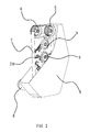
- a surface processing system for a work piece is disposed on the side of the processing center 1 for machining the work piece.
- the work piece to be processed could be a valve, a water faucet or a pipe. All the work pieces share a common feature that the work piece has an inner hole for being held by the manipulator.
- the system includes three groups of polishing unit A which are evenly distributed around the processing unit 1, and storage hoppers for containing processed work pieces are placed around each polishing unit A.
- a manipulator 2 and several polishers 3 having different polishing precisions are provided on the polishing unit A. In particular, four polishers 3 are arranged in sequence around the manipulator 2 and the manipulator 2 could move the work piece between the processing center 1 and the polishing unit A.
- the manipulator 2 When the manipulator 2 is located at the processing unit 1, the manipulator 2 loads all the machined work pieces at one time. When the manipulator 2 is located at the polishing unit A, the work pieces keep being held by the manipulator 2 and are transferred in preset sequence to each polisher 3 corresponding to the polishing unit A where the manipulator 2 is located, for being polished.
- the manipulator 2 includes a base 10, a clamping frame 11 and a clamping arm 12.
- the lower end of the clamping frame 11 is fixedly connected in the axial direction and rotationally connected in the circumferential direction with the base 10.
- a first driving element is provided on the clamping frame 11 for driving the clamping frame 11 to rotate with respect to the base 10 and to be positioned.
- the upper end of the clamping frame 11 is hinged to the clamping arm 12.
- a chuck is set at the front end of the clamping arm 12 to hold the work piece.
- a second driving element is provided between the rear end of the clamping arm 12 and the clamping frame 11 to drive the clamping arm 12 to swing around the hinge point of the clamping frame 11 with the clamping arm 12 and to be positioned.
- the clamping frame 11 of the manipulator rotates to the processing center relative to the base 10 after being driven by the first driving element.
- the work piece within the processing center is held by the clamping arm 12 of the manipulator 2 and then turned into the polishing unit A corresponding to the said manipulator 2.
- the clamping frame 11 is turned by the first driving element into another polisher A relative to the base 10, for being polished for the second time, until the surface of the work piece is polished to the desired precision.
- the clamping arm 12 could rotate by means of the second driving element, so that the height of the clamping arm 12 could be adjusted to facilitate polishing.
- the first driving element comprises a rotary motor 13 fixedly connected to the clamping frame 11.
- a non-rotary fixed gear is fixed on the base 10.
- the clamping frame is connected with a first transmission gear 14 and a third transmission gear which is coaxial with and above the first transmission gear 14.
- a second transmission gear is fixedly connected with the rotation shaft of the rotary motor 13 and engaged with the third transmission gear.
- the first transmission gear 14 is engaged with the aforesaid fixed gear.
- the second driving element includes a swing motor 17 fixedly connected to the middle of the clamping frame 11, a first connection rod 15 and a second connection rod 16.
- One end of the first connection rod 15 is hinged to the swing arm 31 of the swing motor 17, and the other end thereof is hinged to one end of the second connection rod 16.
- the other end of the second connection rod 16 is hinged to the rear end of the clamping arm 12.
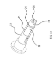
- the chuck includes a cylindrical connection cover 33 and a columnar ejector pin 34 provided within the connection cover 33.
- the ejector pin 34 is circumferentially fixed to the connection cover 33.
- the front end of the connection cover 33 and that of the ejector pin 34 are conical, in which the taper angle of the front end of the ejector pin 34 is larger than that of the front end of the connection cover 33, and the front end of the ejector pin 34 partially extends out of the front end of the connection cover 33.
- indentations 35 are axially provided on the front end of the connection cover 33 to form three elastic sheets 32 at the front end of the connection cover 33.
- An annular shoulder 36 is formed on the outside circumferential surface of the front port of the connection cover 33, which could lock up the work piece. In other words, the annular shoulder 36 is positioned at the end of the elastic sheets 32.
- the inner end of the ejector pin 34 could be connected with the piston rod of the positioning air cylinder 37 mounted with the clamping arm 12.
- Three positioning convex heads 38 are formed on the frond end of the ejector pin 34. The front end of the ejector pin 34 will extend out of the front port of the connection cover 33 under the effect of the piston rod of the positioning air cylinder 37.
- the ejector pin 34 when the ejector pin 34 extends forward, the front end of the connection cover 33 will be extruded to open the front port, i.e., to open the elastic sheets 32 outwards. Therefore, the annular shoulder 36 with an increased diameter will be locked on the inner side wall of the work piece to hold the work piece firmly. Additionally, three positioning convex heads 38 at the front end of the ejector pin 34 are matched with the inner holes of the work piece to ensure the work piece will not rotate circumferentially relative to the chuck.
- the polisher 3 is an abrasive belt polisher, comprising a housing 4, and a driving wheel 5, a driven wheel 6 and an abrasive belt 7 within the housing 4.
- the driving wheel 5 is connected with a polishing motor 8.
- the housing 4 is covered outside of the driving wheel 5 and the driven wheel 6 and a portion of the driving wheel 5 and the driven wheel 6 extends out of the housing 4.
- the abrasive belt 7 is covered on the driving wheel 5 and driven wheel 6 and the outer side of the abrasive belt 7 exposed out of the housing 4 is a polishing surface used for polishing the work piece.
- the polishing motor 8 drives the driving wheel 5 into rotation, which further drives the abrasive belt 7 to rotate.
- the work piece is held by the manipulator 2 to contact the surface of the work piece with the polishing surface on the outer side of the abrasive belt 7 for polishing. Since the polishing surface is exposed out of the housing 4, work pieces of random shapes, including some elongated work pieces, could be processed as such.
- a group of polishing wheels 9 is provided within the housing 4.
- Each of the polishing wheels 9 has a diameter different from that of the remaining polishing wheels 9.
- the remaining polishing wheels 9 are separate from the polishing surface.
- the abrasive belt 7 is pressed by the polishing wheels 9 and the polishing surface of the abrasive belt 7 forms a curved surface having a curvature similar to that of the surface of the work piece to be polished, for which the belt could be conveniently and rapidly polished.
- a transform mechanism is further disposed within the housing 4 to drive the polishing wheels to be pressed against the inner side of the polishing surface.
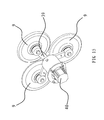
- the transform mechanism includes a transform motor 40 and a connection support 39.
- the central part of the connection support 39 is fixedly connected with the output shaft of the transform motor 40.
- Three self-rotating polishing wheels 9 are placed around the connection support 39.
- the curved surface of the edge of each polishing wheel 9 has a curvature different from others.
- Each polishing wheel 9 is distributed on the same circle centered on the output shaft of the transform motor 40.
- the connection support 39 could be turned to at least press one of the polishing wheels 9 against the back of the abrasive belt 7 in the polisher and position the same.
- the transform mechanism further includes a controller, a proximity switch connected with the controller and induction blocks in the number identical to that of the polishing wheels 9.
- the proximity switch is placed on the outer side of the transform motor 40 and the induction blocks are fixedly connected with the polishing wheels 9 respectively.
- the proximity switch will receive the signal from the induction blocks and send the same to the controller.
- the controller will control the transform motor 40 to stop working and position according to the signal.
- the transform mechanism When the transform mechanism is in use, it is mounted on the inner side of the abrasive belt 7 and the abrasive belt 7 rotate, for which only surfaces of ordinary work pieces could be polished. As for special curved surfaces of the work piece to be polished, the operator could select corresponding polishing wheels 9 according to the curvature of the surface to be polished of the work piece to be processed.
- the connection support 39 and the polishing wheels 9 around the connection support 39 are driven by the transform motor 40 to rotate about the output shaft of the transform motor 39 toward the abrasive belt 7.
- the outer side of the polishing wheel 9 leaned against the abrasive belt 7 is beyond the original position of the abrasive belt 7, and the abrasive belt 7 is pressed against the outer side of the polishing wheel 9. Meanwhile, a shape identical to the polishing curved surface on the outer side of the polishing wheel 9 is formed on the front surface of the abrasive belt 7. As such, the surface of the work piece could be polished by rotating the abrasive
- Each polishing wheel 9 has a radian at the edge different from others in the same polishing unit A.
- the sizes of the abrasive particles of the abrasive belt 7 on adjacent polishers 3 are decreased in turn in the same polishing unit A.
- the polishing precision of the surface of the work piece is gradually increased by polishing the work piece in a series of polishers 3 in which the size of the abrasive particles are decreased.
- the work piece could be held by the manipulator 2 to be polished in a series of polishers 3 in the order of the size of the abrasive particles in the same polishing unit A.
- the manipulator 2 also operates in the polishing unit A for polishing according to the set order.
- a fourth shaft is provided on the processing center 1.
- the work piece could be held for one time and rotate by 360 degrees by using the fourth shaft.
- the work piece is firstly machined by the processing center 1 and the machined work piece is then held by the chuck on the clamping arm 12.
- the clamping arm 12 is driven by the clamping frame 11 to rotate to the polisher 3 in the same polishing unit A for polishing.
- the work piece will move to the next polisher 3 to accomplish the whole polishing process after its surface has been fully polished in the first polisher 3.
- the polishing precision of the surface of the work piece is gradually enhanced.
- the polished work piece will be located in the storage hopper by using the clamping arm 12.
- the machining speed of the work piece by the processing center 1 is higher than the polishing speed of the work piece by the polishers 3, three polishing units A are provided for the processing center in this processing system.
- the work pieces already machined by the processing center 1 could be immediately polished and the production efficiency is guaranteed.
- the work piece is kept stationary when being processed by the processing unit 1, and only one electronic control system is required to control the manipulator 2.
- Preset program could be input into the electronic control system to ensure the clamping arm 12 holds the work piece in the same way every time.
- the molded work pieces will have the same shape. In other words, the processing precision of the work pieces is higher and the integrity thereof is better.
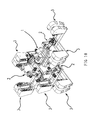
- a surface processing system for a work piece is disposed on the side of the processing center 1 for machining the work piece.
- the system includes polishing units A, a finishing means 18 and a conveyer belt 19 provided between the polishing unit and the finishing means 18, which could drive the work piece to move horizontally.
- a manipulator 2 and four polishers 3 having different polishing precisions are provided on each polishing unit A.
- a mounting support 27 is disposed in each polishing unit A, and the manipulator 2 and each polisher 3 are mounted on the mounting support 27.
- the mounting support 27 is in the shape of a sector.
- the manipulator 2 is fixed at the center of the sector of the mounting support 27.
- All the polishers 3 are evenly distributed on the arc edge of the sector of the mounting support 27.
- the work piece could be moved by the manipulator 2 between the processing center 1 and the polishing unit A.
- the manipulator 2 loads the machined work piece for one time.
- the manipulator 2 keeps holding the work piece and transfers the work piece to each polisher 3 corresponding to the polishing unit A where the manipulator 2 is positioned in a set order, for polishing.
- the manipulator 2 puts the polished work piece on the conveyer belt 19.
- the conveyer belt 19 transfers the work piece to a position close to the finishing means 18.
- the operator places the polished work piece on the conveyer belt 19 in the finishing means 18 for finishing.
- the manipulator is similar to that of the first embodiment except in the first and second driving elements.
- the first driving element comprises a rotary motor 13 fixedly connected to the base 10.
- An annular gear 28 is fixedly connected to the inner side of the clamping frame 11.
- Several intermediate gears 29 are connected with the base 10.
- a first transmission gear 14 is fixedly connected with the rotation shaft of the rotary motor 13.
- the intermediate gears 29 are engaged with the first transmission gear 14 and the annular gear 28 in the meantime.
- the second driving element includes a swing motor 17 fixedly connected to the middle of the clamping frame 11.
- a transmission disk 30 is fixedly connected with the rotation shaft of the swing motor 17.
- One end of the first connection rod 15 is hinged to the edge of the transmission disk 30 and the other end thereof is hinged to one end of the second connection rod 16.
- the other end of the second connection rod 16 is hinged to the back end of the clamping arm 12.
- the transmission disk 30 is fixedly connected with the rotation shaft of the swing motor 17. When the rotation shaft of the swing motor 17 is in rotation, the transmission disk 30 will rotate therewith.
- the polishers 3 are circumferentially distributed in an arc shape about the clamping frame 11 of the manipulator 2.
- the distance from each polisher 3 to the clamping frame 11 is the same as each other.
- the moving distance is the same as each other. In other words, the moving distance of the clamping frame 11 of the manipulator 2 is the same in one polishing unit A.
- the polisher 3 is an abrasive belt polisher comprising a housing 4, and a driving wheel 5, a driven wheel 6 and an abrasive belt 7 within the housing 4.
- the sizes of the abrasive particles of the abrasive belt 7 on adjacent polishers 3 are decreased in turn in the same polishing unit A.
- the driving wheel 5 is connected with a polishing motor 8. A portion of the driving wheel 5 and the driven wheel 6 extends out of the housing 4.
- the abrasive belt 7 is covered on the driving wheel 5 and driven wheel 6 and a polishing surface is formed on the outer side of the abrasive belt 7 out of the housing 4 for polishing the work piece.
- polishing wheels 9 are pressed against the inner side of the polishing surface of the abrasive belt in the housing 4.
- the curved surface at the edge of each of the polishing wheels 9 has a curvature different from that of others, and the diameter of each polishing wheel 9 is different from that of the others.
- a transform mechanism is located at each polishing wheel 9 within the housing 4 for driving the polishing wheel 9.
- Each transform mechanism comprises adjustment guides 20 corresponding to respective polishing wheels 9 disposed within the housing 4 and sliders 21 which are disposed on and could move along the adjustment guides 20.
- Each polishing wheel 9 is connected with its corresponding slider 21.
- the transform mechanism further includes a polishing wheel driving element connected with the slider 21 within the housing 4.
- the polishing wheel driving element is a polishing air cylinder or oil cylinder.
- the piston rod of the polishing air cylinder is fixedly connecte4d with the slider 21.
- the polishing wheel 9 on the slider 21 corresponding to a polishing air cylinder could be pressed against the inner side of the abrasive belt 7 driven by the piston rod of the polishing air cylinder.
- the slider 21 is driven by the polishing wheel driving element to move forward along the adjustment guide 20 and to press the polishing wheel 9 on the slider 21 against the inner side of the abrasive 7.
- Adjustment guides 20 are provided within the housing 4 corresponding to the said three polishing wheels 9 respectively. The same acute angle is formed between every two adjacent adjustment guides 20. Each polishing wheel 9 could be pressed against the same position of the abrasive belt 7.
- the finishing means 18 is located on the side of the polishing unit.
- the finishing means 18 includes a finishing frame 22, a clamp 23 and a finishing wheel 24.
- a finishing guide 25 is disposed horizontally on the finishing frame 22.
- the clamp 23 is located on the finishing guide 25 and the clamp 23 is connected with the finishing driving element which could drive it to move.
- the finishing driving element could be an air cylinder or oil cylinder, and is connected with the clamp 23 via the piston rod of the air or oil cylinder.
- the finishing wheel 24 is connected with the rotation shaft of the finishing motor 26 and is located at the upper part of the finishing frame 22.
- there are two finishing guides 25 which are horizontally disposed.
- a clamp 23 is provided on each of the finishing guides 25.
- finishing wheels 24 There are two finishing wheels 24 respectively corresponding to these two finishing guides 25.
- Two finishing wheels 24 are connected with the same finishing motor 26.
- the finishing wheels 24 are located above the finishing guides 25. Both ends of the rotation shaft of the finishing motor 26 extend out of the casing of the finishing motor 26 respectively.
- Two finishing wheels 24 are connected to both ends of the rotation shaft of the finishing motor 26 respectively.
- a four-axis linkage manipulator is disposed at the processing center 1, which is used to automatically hold the unprocessed work piece and automatically load the work piece at the processing center.
- the clamping frame 11 of the manipulator within each polishing unit A will rotate under control of program preset by the operator.
- the clamping arm 12 of the manipulator 2 thereby rotate with the clamping frame 11 to the processing center 1 and the molded work piece is held by the chuck at the front end of the clamping arm 12.
- the clamping arm 12 will then rotate to the polisher 3 within the same polishing unit A as the manipulator 2 to polish the surface of the work piece.
- the surface processing system of the work piece is controlled by a complete set of programs edited by the operator. Each processing procedure is strictly controlled by the program.
- polishers 3 are provided within the same polishing unit A and the sizes of abrasive particles of the polishers 3 are decreased in turn, after the work piece is held by the clamping arm 12 of the manipulator 2 on the first polisher 3 and subject to all the polishing processes required by the surface thereof, the work piece moves to the next polisher 3 for the same polishing process in which the polishing precision for the surface of the work piece is higher than that in the previous polisher 3. Such a process continues until the work piece is polished by the last polisher 3 in the polishing unit A, for which the surface of the work piece has been polished by four polishers 3 and the highest polishing precision is obtained.
- polishers 3 in the same polishing unit A are distributed in an arc shape about the clamping frame 11, every time the clamping arm 12 is brought by the clamping frame 11 to move from one polisher 3 to the next polisher 3, the moving distance thereof is the same, which significantly simplifies the programming work of the operator and ensures the synchronism of the manipulator 2 in operation.
- the polishing wheel 9 having the same curvature as the curved surface of the work piece will be selected by a program, the slider 21 is pushed outward by the piston rod of the polishing air cylinder corresponding to the polishing wheel 9 to drive the polishing wheel 9 to move forward and press the same against the inner side of the abrasive belt 7, for which a shape is formed on the outer side of the abrasive belt 7 identical to that of the edge of the polishing wheel 9.
- a desired curved surface could be polished on the work piece by contacting the work piece with the shape of the outer side of the abrasive belt 7.
- additional polishing wheels 9 could be selected to repeat the aforesaid process until the surface of the work piece is completely polished.
- the polished work piece is placed by the manipulator 2 on the conveyer belt 19 to be transferred to a position close to the finishing means 18.
- the operator stands next to the finishing means 18 and puts the work piece on the conveyer belt 19 into the clamp 23 of the finishing means 18.
- the clamp 23 moves along to the finishing guide 25 to the finishing wheel 24 driven by the finishing driving element.
- the rotation shaft of the finishing motor 26 drives the finishing wheel 24 to rotate. The surface of the work piece is polished when the work piece is in contact with the finishing wheel 24.
- the machining speed of the work piece by the processing center 1 is higher than the polishing speed of the work piece by the polishing unit A, three polishing units A are provided for surface processing system for the work piece.
- the work pieces already machined by the processing center 1 could be polished in time, for which the production efficiency of the work piece and the utilization rate of the processing center 1 are guaranteed.
- the work piece is kept stationary when being processed by the processing unit 1. It could be ensured that the clamping arm 12 of the manipulator holds the work piece in the same way every time by programming. As a result, the molded work pieces will have the same shape. In other words, the processing precision of the work pieces is higher and the integrity thereof is better.
Landscapes
- Engineering & Computer Science (AREA)
- Mechanical Engineering (AREA)
- Robotics (AREA)
- Finish Polishing, Edge Sharpening, And Grinding By Specific Grinding Devices (AREA)
- Constituent Portions Of Griding Lathes, Driving, Sensing And Control (AREA)
Applications Claiming Priority (2)
| Application Number | Priority Date | Filing Date | Title |
|---|---|---|---|
| CN201310346669.1A CN103419111B (zh) | 2013-08-10 | 2013-08-10 | 一种工件自动加工系统及工件的表面打磨方法 |
| CN201310653014.9A CN103659535B (zh) | 2013-12-06 | 2013-12-06 | 一种工件的表面加工系统 |
Publications (2)
| Publication Number | Publication Date |
|---|---|
| EP2839927A2 true EP2839927A2 (fr) | 2015-02-25 |
| EP2839927A3 EP2839927A3 (fr) | 2016-01-27 |
Family
ID=51263211
Family Applications (1)
| Application Number | Title | Priority Date | Filing Date |
|---|---|---|---|
| EP14177979.3A Withdrawn EP2839927A3 (fr) | 2013-08-10 | 2014-07-22 | Système de traitement de surface pour pièce à usiner |
Country Status (7)
| Country | Link |
|---|---|
| US (1) | US9193024B2 (fr) |
| EP (1) | EP2839927A3 (fr) |
| JP (1) | JP5863902B2 (fr) |
| KR (1) | KR101607190B1 (fr) |
| CA (1) | CA2857213C (fr) |
| IN (1) | IN2014MU02409A (fr) |
| RU (1) | RU2590040C2 (fr) |
Cited By (3)
| Publication number | Priority date | Publication date | Assignee | Title |
|---|---|---|---|---|
| CN105234778A (zh) * | 2015-10-30 | 2016-01-13 | 福建鑫威电器有限公司 | 一种触头焊接触点打磨装置及其加工方法 |
| CN113021142A (zh) * | 2021-03-29 | 2021-06-25 | 胡建雄 | 一种新能源汽车用刹车片打磨设备 |
| CN117464519A (zh) * | 2023-11-17 | 2024-01-30 | 东莞市德一研发有限公司 | 数控磨床及工件研磨方法 |
Families Citing this family (84)
| Publication number | Priority date | Publication date | Assignee | Title |
|---|---|---|---|---|
| CA2855314C (fr) * | 2013-07-02 | 2017-05-09 | Taizhou Federal Robot Technology Co., Ltd. | Appareil de finition et de polissage a courroie abrasive |
| CN105751050A (zh) * | 2016-03-17 | 2016-07-13 | 温州智元知识产权管理有限公司 | 一种针对金属外壳边缘的抛光设备 |
| CN106584243B (zh) * | 2016-12-30 | 2023-05-23 | 台州北平机床有限公司 | 高精度外圆抛光磨床 |
| CN106944917A (zh) * | 2017-03-15 | 2017-07-14 | 广东长盈精密技术有限公司 | 装夹装置及设有该装夹装置的气动打磨头装置 |
| CN106863098A (zh) * | 2017-03-23 | 2017-06-20 | 芜湖瑞德机械科技有限公司 | 一种用于工件加工的机器人臂抛光装置 |
| JP6470336B2 (ja) * | 2017-03-27 | 2019-02-13 | ファナック株式会社 | 工作機械システムおよび移動方法 |
| CN106985045B (zh) * | 2017-03-28 | 2024-01-02 | 湖南宇环精密制造有限公司 | 一种多轴联动打磨设备 |
| CN107052863B (zh) * | 2017-04-18 | 2023-04-18 | 佛山市南海区广工大数控装备协同创新研究院 | 一种柔性机器人抓手及控制方法 |
| CN107116447A (zh) * | 2017-06-05 | 2017-09-01 | 江苏省(扬州)数控机床研究院 | 一种抛光辅助装置 |
| CN107116434A (zh) * | 2017-06-05 | 2017-09-01 | 江苏省(扬州)数控机床研究院 | 一种圆盘抛光机 |
| CN107350943A (zh) * | 2017-08-22 | 2017-11-17 | 广东埃华路机器人工程有限公司 | 一种铜角阀打磨抛光系统 |
| CN107639500A (zh) * | 2017-11-04 | 2018-01-30 | 黄诚广 | 一种电水壶内胆打磨用夹具 |
| CN108145570B (zh) * | 2017-12-05 | 2024-03-01 | 武汉深海弈智科技有限公司 | 一种汽车制动支架上料打磨系统 |
| CN208391672U (zh) * | 2017-12-28 | 2019-01-18 | 佛山市艾乐博机器人科技有限公司 | 一种砂光生产线 |
| CN108161669A (zh) * | 2018-02-01 | 2018-06-15 | 北京华航唯实机器人科技股份有限公司 | 一种基于机器人的流水线式打磨抛光工作站 |
| CN114131637B (zh) * | 2018-02-27 | 2024-02-23 | 福建世高智能科技有限公司 | 一种加工效率高的加工夹具 |
| CN111975640B (zh) * | 2020-08-24 | 2021-09-03 | 青岛理工大学 | 机器人调度下的硬质合金刀片多工序集成自动化生产线 |
| CN108673313A (zh) * | 2018-06-27 | 2018-10-19 | 江门市蓬江区珠西智谷智能装备协同创新研究院 | 一种打磨抛光机器人 |
| CN108818183A (zh) * | 2018-07-30 | 2018-11-16 | 梧州学院 | 推磨专用机械手 |
| TWI669187B (zh) | 2018-08-28 | 2019-08-21 | 財團法人工業技術研究院 | 砂帶機 |
| CN109015333A (zh) * | 2018-09-06 | 2018-12-18 | 国家电网有限公司 | 一种发电机碳刷弧面研磨装置 |
| JP7301512B2 (ja) * | 2018-09-13 | 2023-07-03 | 株式会社岡本工作機械製作所 | 基板研削装置及び基板研削方法 |
| CN109048599B (zh) * | 2018-09-14 | 2024-02-13 | 宏领智能装备(东莞)有限公司 | 一种九轴抛光机 |
| CN108908057B (zh) * | 2018-09-28 | 2024-01-09 | 上海新孚美变速箱技术服务有限公司 | 一种液力变矩器螺栓除锈抛光装置 |
| CN109676511B (zh) * | 2019-02-28 | 2023-08-25 | 杭州职业技术学院 | 一种四面同步抛光机 |
| CN109955134A (zh) * | 2019-04-03 | 2019-07-02 | 江苏准信自动化科技股份有限公司 | 一种稳定型砂带机 |
| CN110370141B (zh) * | 2019-07-02 | 2024-01-02 | 广西师范大学 | 一种木衣架自动仿形打磨机 |
| CN110303416A (zh) * | 2019-07-15 | 2019-10-08 | 广东埃华路机器人工程有限公司 | 一种针对人造髋关节的机器人打磨抛光工站 |
| CN111037449A (zh) * | 2019-11-29 | 2020-04-21 | 浙江钜裕机械设备有限公司 | 一种搅拌式五金抛光机 |
| CN110842745B (zh) * | 2019-12-11 | 2024-05-24 | 江苏宏宝工具有限公司 | 一种螺丝刀的自动抛光装置 |
| CN113442033B (zh) * | 2020-03-25 | 2022-06-10 | 宁波强生电机有限公司 | 一种电机换向器打磨抛光机 |
| US12394651B2 (en) | 2020-04-16 | 2025-08-19 | Applied Materials, Inc. | High throughput polishing modules and modular polishing systems |
| CN111571375B (zh) * | 2020-05-25 | 2021-10-15 | 宁波大榭开发区佳洁锌铸件有限公司 | 一种门把手自动打砂机 |
| US11705354B2 (en) | 2020-07-10 | 2023-07-18 | Applied Materials, Inc. | Substrate handling systems |
| CN111687726A (zh) * | 2020-07-20 | 2020-09-22 | 广东博科数控机械有限公司 | 一种压缩机叶片抛光设备 |
| CN111975577A (zh) * | 2020-07-24 | 2020-11-24 | 上海发那科机器人有限公司 | 一种机器人手持多工件同步打磨方法 |
| CN111941218A (zh) * | 2020-08-18 | 2020-11-17 | 湖北名泰农机有限公司 | 一种四轴抛光机 |
| CN111941238B (zh) * | 2020-09-14 | 2021-09-14 | 苏州君达利智能科技有限公司 | 一种多工位自动磨光机 |
| CN112264892A (zh) * | 2020-10-23 | 2021-01-26 | 山东九鑫机械工具有限公司 | 全自动底弧磨光机 |
| US12198944B2 (en) | 2020-11-11 | 2025-01-14 | Applied Materials, Inc. | Substrate handling in a modular polishing system with single substrate cleaning chambers |
| CN112571253A (zh) * | 2020-11-11 | 2021-03-30 | 徐立君 | 一种厨具加工用红铁木圆菜板切割装置 |
| CN112428114A (zh) * | 2020-12-03 | 2021-03-02 | 广东博科数控机械有限公司 | 一种不锈钢锅胆磨抛生产线 |
| CN112548699B (zh) * | 2020-12-04 | 2022-04-08 | 蜗牛货车网(山东)电子商务有限公司 | 一种汽车传动轴表面精细化处理加工系统 |
| CN112757148B (zh) * | 2020-12-29 | 2022-06-21 | 湖南星科液压有限公司 | 一种用于液压油缸生产的抛光装置 |
| CN112692712B (zh) * | 2020-12-31 | 2025-01-03 | 揭阳市榕星智能设备有限公司 | 一种多级抛光系统 |
| CN112872992B (zh) * | 2021-01-11 | 2022-04-29 | 浙江杭机铸造有限公司 | 一种铸铁件清理专用打磨装置 |
| CN113059452B (zh) * | 2021-04-03 | 2022-06-10 | 唐山替欧特种金属制品有限公司 | 一种金属板材打磨装置 |
| CN113290473A (zh) * | 2021-04-27 | 2021-08-24 | 北京理工大学 | 一种适用于机器人加工的磨抛复合一体化工作站 |
| CN113275996A (zh) * | 2021-06-21 | 2021-08-20 | 肖福女 | 一种新材料表面杂质去除设备 |
| CN113414683B (zh) * | 2021-08-02 | 2024-06-28 | 宁波奥涵机械科技有限公司 | 一种新型铁盒打磨机 |
| CN113752145B (zh) * | 2021-09-08 | 2023-04-11 | 国网福建省电力有限公司营销服务中心 | 拆回的电能表自动清洁抛光装置及其清洁抛光方法 |
| CN113716211B (zh) * | 2021-10-09 | 2022-04-29 | 深圳市歌泰科技有限公司 | 一种led显示屏用防撞保护装置 |
| CN114161266B (zh) * | 2021-11-11 | 2023-03-24 | 佛山中国发明成果转化研究院 | 异形件打磨抛光机 |
| CN114029832B (zh) * | 2021-11-12 | 2023-08-22 | 大连交通大学 | 一种系统控制机械加工设备 |
| CN114161287B (zh) * | 2021-11-15 | 2022-12-23 | 安徽亚珠金刚石股份有限公司 | 一种树脂基金刚石复合磨具 |
| CN114147619A (zh) * | 2021-12-16 | 2022-03-08 | 新昌浙江工业大学科学技术研究院 | 带专用定位夹持装置的薄壁环形零件抛光装置及抛光方法 |
| CN114700842A (zh) * | 2022-03-31 | 2022-07-05 | 重庆山朕科技发展有限公司 | 一种砂带式凸焊电极修磨装置 |
| CN114632976B (zh) * | 2022-04-13 | 2023-09-05 | 绍兴文理学院元培学院 | 一种齿轮打磨装置 |
| CN114654354B (zh) * | 2022-04-16 | 2023-07-18 | 华瑞(江苏)燃机服务有限公司 | 一种动叶磨削加工用可切换砂带驱动主轴箱 |
| CN114654355B (zh) * | 2022-04-16 | 2023-07-28 | 华瑞(江苏)燃机服务有限公司 | 一种动叶叶尖焊后数控打磨专机 |
| CN114918798B (zh) * | 2022-05-12 | 2023-06-30 | 新昌浙江工业大学科学技术研究院 | 手表壳正反面抛光装置及抛光方法 |
| CN114833588A (zh) * | 2022-07-06 | 2022-08-02 | 徐州德龙灌排设备有限公司 | 一种农业灌溉式喷枪用法兰盘配件的加工机床 |
| CN115042064B (zh) * | 2022-08-16 | 2022-11-01 | 徐州旭佩辰机械科技有限公司 | 一种十字滑块联轴器加工用抛光装置 |
| CN115383594B (zh) * | 2022-08-31 | 2024-02-20 | 南京宏亚建设集团有限公司 | 一种建筑工程用钢管表面除锈装置 |
| CN115648012B (zh) * | 2022-11-01 | 2024-02-13 | 江苏煌朝真空玻璃科技有限公司 | 一种玻璃制品表面处理设备 |
| CN115673951A (zh) * | 2022-11-17 | 2023-02-03 | 浙江恒成硬质合金有限公司 | 顶锤锥度外圆抛光倒角设备 |
| CN116117642B (zh) * | 2022-12-29 | 2026-03-24 | 无锡盈连科技有限公司 | 一种可结合工业机器人的力控砂带机 |
| CN116810582A (zh) * | 2023-02-15 | 2023-09-29 | 中国工程物理研究院电子工程研究所 | 一种用于导电片的砂带精密尺寸‘b’值抛光工艺 |
| CN116061028B (zh) * | 2023-03-02 | 2023-06-13 | 湖南金岭机床科技集团有限公司 | 一种多柱高精密抛光机的载盘定位装置 |
| CN116141161B (zh) * | 2023-03-06 | 2023-09-15 | 江苏安迪泰机车制造有限公司 | 一种三轮车车厢打磨机 |
| CN116372765B (zh) * | 2023-03-31 | 2024-04-05 | 东莞市春草研磨科技有限公司 | 一种研磨抛光设备用的转换磨头 |
| US12224186B2 (en) | 2023-04-03 | 2025-02-11 | Applied Materials, Inc. | Apparatus and method of brush cleaning using periodic chemical treatments |
| CN116330109B (zh) * | 2023-05-26 | 2023-08-15 | 烟台三环制锁科技有限公司 | 一种锁具总成批量抛光加工装置 |
| CN116872061B (zh) * | 2023-08-14 | 2025-08-12 | 江苏仓环铜业股份有限公司 | 一种带有安全防护系统的抛光机 |
| CN117564895A (zh) * | 2023-11-02 | 2024-02-20 | 江门市依山金属制品有限公司 | 一种全自动锅具抛光机 |
| CN117601001B (zh) * | 2024-01-22 | 2024-04-09 | 合肥精亿工贸有限公司 | 一种适用于汽车金属零部件加工用抛光设备 |
| CN118513618B (zh) * | 2024-04-29 | 2025-02-21 | 江苏省艾格森数控设备制造有限公司 | 一种三棱针放电加工旋转分度装置 |
| CN118893532B (zh) * | 2024-10-09 | 2024-12-20 | 南通华宇紧固件有限公司 | 一种电器用紧固件表面抛光装置 |
| CN119057646B (zh) * | 2024-11-05 | 2025-04-18 | 博瑞孚曼机械科技(苏州)有限公司 | 一种辊压高强钢异形产品自动打磨设备及方法 |
| CN119706343B (zh) * | 2024-12-10 | 2025-09-30 | 清远市震东电子科技有限公司 | 一种一体电感生产用抓取装置及上下料设备 |
| CN119681759B (zh) * | 2024-12-23 | 2025-09-26 | 广东米克智能科技有限公司 | 一种数控机床用电动机械手 |
| CN119457211B (zh) * | 2025-01-15 | 2025-05-20 | 厦门理工学院 | 一种缸套内侧铣削装置 |
| CN119750214B (zh) * | 2025-02-17 | 2025-11-11 | 元博智能科技(惠州)有限公司 | 一种快速旋转物料移载结构 |
| CN120921430B (zh) * | 2025-10-15 | 2026-01-27 | 山西机电职业技术学院 | 一种铸造型壳用自动化夹持机械手 |
Citations (1)
| Publication number | Priority date | Publication date | Assignee | Title |
|---|---|---|---|---|
| WO2001089764A1 (fr) * | 2000-05-26 | 2001-11-29 | John Lewis Price | Appareil de meulage |
Family Cites Families (29)
| Publication number | Priority date | Publication date | Assignee | Title |
|---|---|---|---|---|
| US1844165A (en) * | 1929-06-07 | 1932-02-09 | Kabelac Frank | Abrading machine |
| US2594646A (en) * | 1946-11-30 | 1952-04-29 | Bror G Olving | Polishing machine |
| JPS58109263A (ja) * | 1981-12-23 | 1983-06-29 | Shimura Tekkosho:Kk | 木工用プロフイルサンダ |
| SU1266711A1 (ru) * | 1984-08-29 | 1986-10-30 | Предприятие П/Я В-2897 | Роботизированный технологический комплекс |
| US4653231A (en) * | 1985-11-01 | 1987-03-31 | Motorola, Inc. | Polishing system with underwater Bernoulli pickup |
| SU1450976A1 (ru) * | 1986-12-15 | 1989-01-15 | Предприятие П/Я Р-6896 | Автоматическа лини дл обработки плоских поверхностей изделий |
| SU1509277A1 (ru) * | 1987-06-08 | 1989-09-23 | Предприятие П/Я Р-6284 | Устройство дл сварки изделий из термопластичного материала |
| FR2636556A1 (fr) * | 1988-09-19 | 1990-03-23 | Marunaga & Co Ltd | |
| SU1734985A1 (ru) * | 1990-02-08 | 1992-05-23 | Ленинградское оптико-механическое объединение им.В.И.Ленина | Устройство дл шлифовани фасок |
| JPH04300162A (ja) * | 1991-02-08 | 1992-10-23 | Yamaha Motor Co Ltd | 表面仕上げ方法および装置 |
| JP2548936Y2 (ja) * | 1992-03-27 | 1997-09-24 | 株式会社アーレスティ | 製品積込み装置のチャック |
| JPH0663862A (ja) * | 1992-08-22 | 1994-03-08 | Fujikoshi Mach Corp | 研磨装置 |
| JP3696690B2 (ja) * | 1996-04-23 | 2005-09-21 | 不二越機械工業株式会社 | ウェーハの研磨装置システム |
| JPH11320370A (ja) * | 1998-05-14 | 1999-11-24 | Soken Kogyo Kk | ベルト研磨装置 |
| JP2001219354A (ja) * | 2000-02-04 | 2001-08-14 | Kawasaki Heavy Ind Ltd | 研磨システム |
| DE10013340C2 (de) * | 2000-03-17 | 2003-04-03 | Carat Robotic Innovation Gmbh | Bandschleifmaschine mit Andruckregelung |
| US6991524B1 (en) * | 2000-07-07 | 2006-01-31 | Disc Go Technologies Inc. | Method and apparatus for reconditioning digital discs |
| TWI295950B (en) * | 2002-10-03 | 2008-04-21 | Applied Materials Inc | Method for reducing delamination during chemical mechanical polishing |
| JP2004314201A (ja) * | 2003-04-11 | 2004-11-11 | Yoshida Kinzoku Kogyo Kk | 刃付け用ロボットハンド及びこれを備えた刃付けロボット |
| US7083505B2 (en) * | 2003-09-16 | 2006-08-01 | Acme Manufacturing Company | Stacked triple wheel head assembly |
| US7273408B2 (en) * | 2005-12-16 | 2007-09-25 | Applied Materials, Inc. | Paired pivot arm |
| EP2014413A1 (fr) * | 2007-07-12 | 2009-01-14 | Lufthansa Technik AG | Agencement, procédé et dispositif destinés à l'entretien d'aubes de turbines à gaz |
| CN201189633Y (zh) * | 2008-05-20 | 2009-02-04 | 郑建军 | 一种抛光装置 |
| JP2010042461A (ja) * | 2008-08-11 | 2010-02-25 | Sharp Corp | 搬送装置および機器の製造方法 |
| WO2010045151A2 (fr) * | 2008-10-16 | 2010-04-22 | Applied Materials, Inc. | Platine texturée |
| JP5498469B2 (ja) * | 2011-11-18 | 2014-05-21 | 本田技研工業株式会社 | 把持部位置決め装置および方法 |
| CN102441835A (zh) | 2011-12-08 | 2012-05-09 | 高健生 | 一种双面抛光机 |
| CN202726687U (zh) | 2012-07-05 | 2013-02-13 | 广州遂联自动化设备有限公司 | 双面抛光机 |
| JP2014167996A (ja) * | 2013-02-28 | 2014-09-11 | Ebara Corp | 研磨装置および研磨方法 |
-
2014
- 2014-07-18 CA CA2857213A patent/CA2857213C/fr active Active
- 2014-07-22 EP EP14177979.3A patent/EP2839927A3/fr not_active Withdrawn
- 2014-07-24 KR KR1020140094046A patent/KR101607190B1/ko not_active Expired - Fee Related
- 2014-07-25 IN IN2409MU2014 patent/IN2014MU02409A/en unknown
- 2014-07-26 US US14/341,785 patent/US9193024B2/en not_active Expired - Fee Related
- 2014-07-29 JP JP2014153804A patent/JP5863902B2/ja active Active
- 2014-08-04 RU RU2014132091/02A patent/RU2590040C2/ru not_active IP Right Cessation
Patent Citations (1)
| Publication number | Priority date | Publication date | Assignee | Title |
|---|---|---|---|---|
| WO2001089764A1 (fr) * | 2000-05-26 | 2001-11-29 | John Lewis Price | Appareil de meulage |
Cited By (4)
| Publication number | Priority date | Publication date | Assignee | Title |
|---|---|---|---|---|
| CN105234778A (zh) * | 2015-10-30 | 2016-01-13 | 福建鑫威电器有限公司 | 一种触头焊接触点打磨装置及其加工方法 |
| CN113021142A (zh) * | 2021-03-29 | 2021-06-25 | 胡建雄 | 一种新能源汽车用刹车片打磨设备 |
| CN113021142B (zh) * | 2021-03-29 | 2023-11-03 | 烟台成宇汽车部件有限公司 | 一种新能源汽车用刹车片打磨设备 |
| CN117464519A (zh) * | 2023-11-17 | 2024-01-30 | 东莞市德一研发有限公司 | 数控磨床及工件研磨方法 |
Also Published As
| Publication number | Publication date |
|---|---|
| KR101607190B1 (ko) | 2016-03-29 |
| JP2015036188A (ja) | 2015-02-23 |
| US9193024B2 (en) | 2015-11-24 |
| CA2857213C (fr) | 2016-11-22 |
| JP5863902B2 (ja) | 2016-02-17 |
| IN2014MU02409A (fr) | 2015-10-09 |
| KR20150018384A (ko) | 2015-02-23 |
| RU2590040C2 (ru) | 2016-07-10 |
| CA2857213A1 (fr) | 2015-02-10 |
| EP2839927A3 (fr) | 2016-01-27 |
| US20150044944A1 (en) | 2015-02-12 |
| RU2014132091A (ru) | 2016-02-20 |
Similar Documents
| Publication | Publication Date | Title |
|---|---|---|
| US9193024B2 (en) | Surface processing system for a work piece | |
| CN205363484U (zh) | 一种平行同步多轴数控自动抛光设备 | |
| CN103419111B (zh) | 一种工件自动加工系统及工件的表面打磨方法 | |
| CN104772687B (zh) | 一种回转式多工位水晶磨抛一体机 | |
| US10058969B2 (en) | Dual-spindle grinding machine | |
| JP2008279594A (ja) | ワークの精密仕上げのための精密加工装置 | |
| JP6810099B2 (ja) | 内歯を有するワークピースの面取りを行うための装置及び方法 | |
| CN109396976A (zh) | 一种周边磨床 | |
| CN103659535A (zh) | 一种工件的表面加工系统 | |
| CN203509858U (zh) | 一种工件自动加工系统 | |
| KR101683593B1 (ko) | 수평형 호닝가공장치 | |
| CN102430962B (zh) | 一种机械加工设备 | |
| KR20030041814A (ko) | 글래스 시이트의 코너 라운딩 기계 | |
| CN216577234U (zh) | 一种异形复杂配件打磨设备用同步旋转工作台 | |
| CN203804738U (zh) | 一种工件的表面加工系统 | |
| EP3922407B1 (fr) | Machine pour le diamantage de corps allongés | |
| CN110977668A (zh) | 一种数控全自动一次成型凸轮轴毛坯打磨机床 | |
| CN105598811A (zh) | 一种用于弯头内表面抛光的抛光机 | |
| CN211681537U (zh) | 一种干湿两用智能无损镜面研磨抛光机 | |
| CN214054412U (zh) | 一种数控加工用工件夹具 | |
| CN104128861A (zh) | 一种圆形玻璃磨边机 | |
| US2534941A (en) | Method and apparatus for grinding | |
| CN206998505U (zh) | 一种万向转动的弧形石材加工设备 | |
| CN221313244U (zh) | 一种内台形导向段螺纹成型装置 | |
| CN112108911A (zh) | 一种数控加工用工件夹具 |
Legal Events
| Date | Code | Title | Description |
|---|---|---|---|
| PUAI | Public reference made under article 153(3) epc to a published international application that has entered the european phase |
Free format text: ORIGINAL CODE: 0009012 |
|
| 17P | Request for examination filed |
Effective date: 20140722 |
|
| AK | Designated contracting states |
Kind code of ref document: A2 Designated state(s): AL AT BE BG CH CY CZ DE DK EE ES FI FR GB GR HR HU IE IS IT LI LT LU LV MC MK MT NL NO PL PT RO RS SE SI SK SM TR |
|
| AX | Request for extension of the european patent |
Extension state: BA ME |
|
| RIC1 | Information provided on ipc code assigned before grant |
Ipc: B24B 41/00 20060101ALI20150903BHEP Ipc: B25J 15/00 20060101ALI20150903BHEP Ipc: B25J 9/00 20060101ALI20150903BHEP Ipc: B23Q 39/02 20060101ALI20150903BHEP Ipc: B24B 55/04 20060101ALI20150903BHEP Ipc: B24B 21/12 20060101ALI20150903BHEP Ipc: B24B 27/00 20060101ALI20150903BHEP Ipc: B23Q 7/04 20060101ALI20150903BHEP Ipc: B24B 21/18 20060101ALI20150903BHEP Ipc: B24B 21/20 20060101ALI20150903BHEP Ipc: B24B 21/00 20060101AFI20150903BHEP Ipc: B24B 41/06 20120101ALI20150903BHEP Ipc: B24B 21/16 20060101ALI20150903BHEP |
|
| PUAL | Search report despatched |
Free format text: ORIGINAL CODE: 0009013 |
|
| AK | Designated contracting states |
Kind code of ref document: A3 Designated state(s): AL AT BE BG CH CY CZ DE DK EE ES FI FR GB GR HR HU IE IS IT LI LT LU LV MC MK MT NL NO PL PT RO RS SE SI SK SM TR |
|
| AX | Request for extension of the european patent |
Extension state: BA ME |
|
| RIC1 | Information provided on ipc code assigned before grant |
Ipc: B24B 55/04 20060101ALI20151223BHEP Ipc: B24B 27/00 20060101ALI20151223BHEP Ipc: B25J 9/00 20060101ALI20151223BHEP Ipc: B23Q 39/02 20060101ALI20151223BHEP Ipc: B24B 21/16 20060101ALI20151223BHEP Ipc: B24B 41/06 20120101ALI20151223BHEP Ipc: B24B 21/20 20060101ALI20151223BHEP Ipc: B24B 21/12 20060101ALI20151223BHEP Ipc: B24B 21/00 20060101AFI20151223BHEP Ipc: B24B 41/00 20060101ALI20151223BHEP Ipc: B25J 15/00 20060101ALI20151223BHEP Ipc: B23Q 7/04 20060101ALI20151223BHEP Ipc: B24B 21/18 20060101ALI20151223BHEP |
|
| RBV | Designated contracting states (corrected) |
Designated state(s): AL AT BE BG CH CY CZ DE DK EE ES FI FR GB GR HR HU IE IS IT LI LT LU LV MC MK MT NL NO PL PT RO RS SE SI SK SM TR |
|
| RAP1 | Party data changed (applicant data changed or rights of an application transferred) |
Owner name: WUHU HUIYING AUTOMATIC EQUIPMENT CO., LTD. |
|
| STAA | Information on the status of an ep patent application or granted ep patent |
Free format text: STATUS: EXAMINATION IS IN PROGRESS |
|
| 17Q | First examination report despatched |
Effective date: 20190329 |
|
| STAA | Information on the status of an ep patent application or granted ep patent |
Free format text: STATUS: THE APPLICATION IS DEEMED TO BE WITHDRAWN |
|
| 18D | Application deemed to be withdrawn |
Effective date: 20220421 |