EP2839947B1 - Beschichtungsverfahren für eine leitung und verwendung eines beschichtungsmaterials bei diesem verfahren - Google Patents
Beschichtungsverfahren für eine leitung und verwendung eines beschichtungsmaterials bei diesem verfahren Download PDFInfo
- Publication number
- EP2839947B1 EP2839947B1 EP12874221.0A EP12874221A EP2839947B1 EP 2839947 B1 EP2839947 B1 EP 2839947B1 EP 12874221 A EP12874221 A EP 12874221A EP 2839947 B1 EP2839947 B1 EP 2839947B1
- Authority
- EP
- European Patent Office
- Prior art keywords
- lining material
- conduit
- woven fabric
- material sheet
- lining
- Prior art date
- Legal status (The legal status is an assumption and is not a legal conclusion. Google has not performed a legal analysis and makes no representation as to the accuracy of the status listed.)
- Active
Links
Images






Classifications
-
- F—MECHANICAL ENGINEERING; LIGHTING; HEATING; WEAPONS; BLASTING
- F16—ENGINEERING ELEMENTS AND UNITS; GENERAL MEASURES FOR PRODUCING AND MAINTAINING EFFECTIVE FUNCTIONING OF MACHINES OR INSTALLATIONS; THERMAL INSULATION IN GENERAL
- F16L—PIPES; JOINTS OR FITTINGS FOR PIPES; SUPPORTS FOR PIPES, CABLES OR PROTECTIVE TUBING; MEANS FOR THERMAL INSULATION IN GENERAL
- F16L55/00—Devices or appurtenances for use in, or in connection with, pipes or pipe systems
- F16L55/16—Devices for covering leaks in pipes or hoses, e.g. hose-menders
- F16L55/162—Devices for covering leaks in pipes or hoses, e.g. hose-menders from inside the pipe
- F16L55/165—Devices for covering leaks in pipes or hoses, e.g. hose-menders from inside the pipe a pipe or flexible liner being inserted in the damaged section
- F16L55/1652—Devices for covering leaks in pipes or hoses, e.g. hose-menders from inside the pipe a pipe or flexible liner being inserted in the damaged section the flexible liner being pulled into the damaged section
- F16L55/1654—Devices for covering leaks in pipes or hoses, e.g. hose-menders from inside the pipe a pipe or flexible liner being inserted in the damaged section the flexible liner being pulled into the damaged section and being inflated
-
- B—PERFORMING OPERATIONS; TRANSPORTING
- B29—WORKING OF PLASTICS; WORKING OF SUBSTANCES IN A PLASTIC STATE IN GENERAL
- B29C—SHAPING OR JOINING OF PLASTICS; SHAPING OF MATERIAL IN A PLASTIC STATE, NOT OTHERWISE PROVIDED FOR; AFTER-TREATMENT OF THE SHAPED PRODUCTS, e.g. REPAIRING
- B29C63/00—Lining or sheathing, i.e. applying preformed layers or sheathings of plastics; Apparatus therefor
- B29C63/26—Lining or sheathing of internal surfaces
- B29C63/34—Lining or sheathing of internal surfaces using tubular layers or sheathings
-
- B—PERFORMING OPERATIONS; TRANSPORTING
- B32—LAYERED PRODUCTS
- B32B—LAYERED PRODUCTS, i.e. PRODUCTS BUILT-UP OF STRATA OF FLAT OR NON-FLAT, e.g. CELLULAR OR HONEYCOMB, FORM
- B32B1/00—Layered products having a non-planar shape
- B32B1/08—Tubular products
-
- B—PERFORMING OPERATIONS; TRANSPORTING
- B32—LAYERED PRODUCTS
- B32B—LAYERED PRODUCTS, i.e. PRODUCTS BUILT-UP OF STRATA OF FLAT OR NON-FLAT, e.g. CELLULAR OR HONEYCOMB, FORM
- B32B3/00—Layered products comprising a layer with external or internal discontinuities or unevennesses, or a layer of non-planar shape; Layered products comprising a layer having particular features of form
- B32B3/02—Layered products comprising a layer with external or internal discontinuities or unevennesses, or a layer of non-planar shape; Layered products comprising a layer having particular features of form characterised by features of form at particular places, e.g. in edge regions
-
- B—PERFORMING OPERATIONS; TRANSPORTING
- B32—LAYERED PRODUCTS
- B32B—LAYERED PRODUCTS, i.e. PRODUCTS BUILT-UP OF STRATA OF FLAT OR NON-FLAT, e.g. CELLULAR OR HONEYCOMB, FORM
- B32B5/00—Layered products characterised by the non- homogeneity or physical structure, i.e. comprising a fibrous, filamentary, particulate or foam layer; Layered products characterised by having a layer differing constitutionally or physically in different parts
- B32B5/02—Layered products characterised by the non- homogeneity or physical structure, i.e. comprising a fibrous, filamentary, particulate or foam layer; Layered products characterised by having a layer differing constitutionally or physically in different parts characterised by structural features of a fibrous or filamentary layer
- B32B5/022—Non-woven fabric
-
- B—PERFORMING OPERATIONS; TRANSPORTING
- B32—LAYERED PRODUCTS
- B32B—LAYERED PRODUCTS, i.e. PRODUCTS BUILT-UP OF STRATA OF FLAT OR NON-FLAT, e.g. CELLULAR OR HONEYCOMB, FORM
- B32B5/00—Layered products characterised by the non- homogeneity or physical structure, i.e. comprising a fibrous, filamentary, particulate or foam layer; Layered products characterised by having a layer differing constitutionally or physically in different parts
- B32B5/02—Layered products characterised by the non- homogeneity or physical structure, i.e. comprising a fibrous, filamentary, particulate or foam layer; Layered products characterised by having a layer differing constitutionally or physically in different parts characterised by structural features of a fibrous or filamentary layer
- B32B5/024—Woven fabric
-
- B—PERFORMING OPERATIONS; TRANSPORTING
- B32—LAYERED PRODUCTS
- B32B—LAYERED PRODUCTS, i.e. PRODUCTS BUILT-UP OF STRATA OF FLAT OR NON-FLAT, e.g. CELLULAR OR HONEYCOMB, FORM
- B32B5/00—Layered products characterised by the non- homogeneity or physical structure, i.e. comprising a fibrous, filamentary, particulate or foam layer; Layered products characterised by having a layer differing constitutionally or physically in different parts
- B32B5/02—Layered products characterised by the non- homogeneity or physical structure, i.e. comprising a fibrous, filamentary, particulate or foam layer; Layered products characterised by having a layer differing constitutionally or physically in different parts characterised by structural features of a fibrous or filamentary layer
- B32B5/06—Layered products characterised by the non- homogeneity or physical structure, i.e. comprising a fibrous, filamentary, particulate or foam layer; Layered products characterised by having a layer differing constitutionally or physically in different parts characterised by structural features of a fibrous or filamentary layer characterised by a fibrous or filamentary layer mechanically connected, e.g. by needling to another layer, e.g. of fibres, of paper
-
- B—PERFORMING OPERATIONS; TRANSPORTING
- B32—LAYERED PRODUCTS
- B32B—LAYERED PRODUCTS, i.e. PRODUCTS BUILT-UP OF STRATA OF FLAT OR NON-FLAT, e.g. CELLULAR OR HONEYCOMB, FORM
- B32B5/00—Layered products characterised by the non- homogeneity or physical structure, i.e. comprising a fibrous, filamentary, particulate or foam layer; Layered products characterised by having a layer differing constitutionally or physically in different parts
- B32B5/22—Layered products characterised by the non- homogeneity or physical structure, i.e. comprising a fibrous, filamentary, particulate or foam layer; Layered products characterised by having a layer differing constitutionally or physically in different parts characterised by the presence of two or more layers which are next to each other and are fibrous, filamentary, formed of particles or foamed
- B32B5/24—Layered products characterised by the non- homogeneity or physical structure, i.e. comprising a fibrous, filamentary, particulate or foam layer; Layered products characterised by having a layer differing constitutionally or physically in different parts characterised by the presence of two or more layers which are next to each other and are fibrous, filamentary, formed of particles or foamed one layer being a fibrous or filamentary layer
- B32B5/26—Layered products characterised by the non- homogeneity or physical structure, i.e. comprising a fibrous, filamentary, particulate or foam layer; Layered products characterised by having a layer differing constitutionally or physically in different parts characterised by the presence of two or more layers which are next to each other and are fibrous, filamentary, formed of particles or foamed one layer being a fibrous or filamentary layer another layer next to it also being fibrous or filamentary
-
- F—MECHANICAL ENGINEERING; LIGHTING; HEATING; WEAPONS; BLASTING
- F16—ENGINEERING ELEMENTS AND UNITS; GENERAL MEASURES FOR PRODUCING AND MAINTAINING EFFECTIVE FUNCTIONING OF MACHINES OR INSTALLATIONS; THERMAL INSULATION IN GENERAL
- F16L—PIPES; JOINTS OR FITTINGS FOR PIPES; SUPPORTS FOR PIPES, CABLES OR PROTECTIVE TUBING; MEANS FOR THERMAL INSULATION IN GENERAL
- F16L55/00—Devices or appurtenances for use in, or in connection with, pipes or pipe systems
- F16L55/16—Devices for covering leaks in pipes or hoses, e.g. hose-menders
- F16L55/162—Devices for covering leaks in pipes or hoses, e.g. hose-menders from inside the pipe
- F16L55/165—Devices for covering leaks in pipes or hoses, e.g. hose-menders from inside the pipe a pipe or flexible liner being inserted in the damaged section
- F16L55/1652—Devices for covering leaks in pipes or hoses, e.g. hose-menders from inside the pipe a pipe or flexible liner being inserted in the damaged section the flexible liner being pulled into the damaged section
- F16L55/1653—Devices for covering leaks in pipes or hoses, e.g. hose-menders from inside the pipe a pipe or flexible liner being inserted in the damaged section the flexible liner being pulled into the damaged section and being pressed into contact with the pipe by a tool which moves inside along the pipe
-
- F—MECHANICAL ENGINEERING; LIGHTING; HEATING; WEAPONS; BLASTING
- F16—ENGINEERING ELEMENTS AND UNITS; GENERAL MEASURES FOR PRODUCING AND MAINTAINING EFFECTIVE FUNCTIONING OF MACHINES OR INSTALLATIONS; THERMAL INSULATION IN GENERAL
- F16L—PIPES; JOINTS OR FITTINGS FOR PIPES; SUPPORTS FOR PIPES, CABLES OR PROTECTIVE TUBING; MEANS FOR THERMAL INSULATION IN GENERAL
- F16L55/00—Devices or appurtenances for use in, or in connection with, pipes or pipe systems
- F16L55/16—Devices for covering leaks in pipes or hoses, e.g. hose-menders
- F16L55/162—Devices for covering leaks in pipes or hoses, e.g. hose-menders from inside the pipe
- F16L55/165—Devices for covering leaks in pipes or hoses, e.g. hose-menders from inside the pipe a pipe or flexible liner being inserted in the damaged section
- F16L55/1656—Devices for covering leaks in pipes or hoses, e.g. hose-menders from inside the pipe a pipe or flexible liner being inserted in the damaged section materials for flexible liners
-
- B—PERFORMING OPERATIONS; TRANSPORTING
- B29—WORKING OF PLASTICS; WORKING OF SUBSTANCES IN A PLASTIC STATE IN GENERAL
- B29L—INDEXING SCHEME ASSOCIATED WITH SUBCLASS B29C, RELATING TO PARTICULAR ARTICLES
- B29L2023/00—Tubular articles
- B29L2023/004—Bent tubes
-
- B—PERFORMING OPERATIONS; TRANSPORTING
- B32—LAYERED PRODUCTS
- B32B—LAYERED PRODUCTS, i.e. PRODUCTS BUILT-UP OF STRATA OF FLAT OR NON-FLAT, e.g. CELLULAR OR HONEYCOMB, FORM
- B32B2260/00—Layered product comprising an impregnated, embedded, or bonded layer wherein the layer comprises an impregnation, embedding, or binder material
- B32B2260/02—Composition of the impregnated, bonded or embedded layer
- B32B2260/021—Fibrous or filamentary layer
- B32B2260/023—Two or more layers
-
- B—PERFORMING OPERATIONS; TRANSPORTING
- B32—LAYERED PRODUCTS
- B32B—LAYERED PRODUCTS, i.e. PRODUCTS BUILT-UP OF STRATA OF FLAT OR NON-FLAT, e.g. CELLULAR OR HONEYCOMB, FORM
- B32B2260/00—Layered product comprising an impregnated, embedded, or bonded layer wherein the layer comprises an impregnation, embedding, or binder material
- B32B2260/04—Impregnation, embedding, or binder material
- B32B2260/046—Synthetic resin
-
- B—PERFORMING OPERATIONS; TRANSPORTING
- B32—LAYERED PRODUCTS
- B32B—LAYERED PRODUCTS, i.e. PRODUCTS BUILT-UP OF STRATA OF FLAT OR NON-FLAT, e.g. CELLULAR OR HONEYCOMB, FORM
- B32B2262/00—Composition or structural features of fibres which form a fibrous or filamentary layer or are present as additives
- B32B2262/02—Synthetic macromolecular fibres
-
- B—PERFORMING OPERATIONS; TRANSPORTING
- B32—LAYERED PRODUCTS
- B32B—LAYERED PRODUCTS, i.e. PRODUCTS BUILT-UP OF STRATA OF FLAT OR NON-FLAT, e.g. CELLULAR OR HONEYCOMB, FORM
- B32B2262/00—Composition or structural features of fibres which form a fibrous or filamentary layer or are present as additives
- B32B2262/10—Inorganic fibres
- B32B2262/101—Glass fibres
-
- B—PERFORMING OPERATIONS; TRANSPORTING
- B32—LAYERED PRODUCTS
- B32B—LAYERED PRODUCTS, i.e. PRODUCTS BUILT-UP OF STRATA OF FLAT OR NON-FLAT, e.g. CELLULAR OR HONEYCOMB, FORM
- B32B2597/00—Tubular articles, e.g. hoses, pipes
Definitions
- the present invention relates to: a method for lining a conduit; and a use of a lining material in that method.
- a tubular lining material including a liquid curable resin and reinforced fibers is installed on an inner surface of the existing conduit, and then the liquid curable resin is cured, thereby to construct a robust lining structure formed by a fiber reinforced resin, in the conduit.
- Patent Literature 1 discloses the hollowing method.
- a lining material sheet including high-strength short fibers spread on a liquid thermosetting resin (sheet molding compound: SMC) is rolled into a tubular lining material, and the lining material is installed in a conduit with both ends of the lining material sheet overlapping each other so as to be slidable on each other.
- a pressurized fluid is supplied to apply an internal pressure to the tubular lining material, thereby expanding the diameter of thereof while sliding the both ends of the lining material sheet on each other, with the result that the lining material is brought into a close contact with an inner surface of the conduit.
- a heating medium such as steam is supplied into the lining material, to set the liquid thermosetting resin included in the lining material.
- Patent Literature 1 Japanese Unexamined Patent Publication No. 278177/1993 ( Tokukaihei 05-278177 )
- JP 2001 116 165 A teaches a method for lining a conduit having a bending portion. From that method the features according to the preamble of Claim 1 are known.
- JP 2001 047 512 A teaches a method for lining a conduit, wherein an overlapping portion of both ends of a lining material sheet is sewed. The possibility of the ends of the lining material sliding on each other or the position of the overlapping portion in relation to a bending portion of the conduit are not disclosed.
- JP 2004 144 137 A teaches a method for lining a conduit, wherein a thicker section of the lining is placed in the bending portion of the conduit, in order for that section of the lining not to buckle.
- US 5,950,682 A teaches a method for lining a conduit, wherein an overlapping portion of both ends of a lining material sheet is shown not to face toward an outer curvature side of the bending portion, in the bending portion of a conduit.
- An object of the present invention is to minimize the gap between the lining material and the inner surface of the conduit, in the bending portion of the conduit.
- the present invention proposes a method for lining a conduit having a bending portion in accordance with the features of claim 1.
- the method includes: an installation step of installing in the conduit a lining material obtained by rolling a lining material sheet into a tubular form, with both ends of the lining material sheet in its circumferential direction circumferentially overlapping each other; and a diameter expansion step of expanding a diameter of the lining material installed in the conduit while circumferentially sliding the both ends of the lining material sheet on each other.
- the lining material is installed so that an overlapping portion where the both ends of the lining material sheet overlap each other faces toward an outer curvature side of the bending portion, in the bending portion of the conduit.
- the lining material is installed in the installation step so that the overlapping portion of the both ends of the lining material sheet faces toward the outer curvature side of the bending portion, in the bending portion of the conduit. Therefore, when the diameter of the lining material is expanded in the subsequent diameter expansion step, the both ends of the lining material sheet circumferentially slide on each other, while facing toward the outer curvature side of the bending portion. This facilitates inflation of a portion of the lining material which portion faces toward the outer curvature side. Consequently, a gap between the inner surface of the bending portion and the lining material is decreased, and it is more likely that the lining material fits the inner surface of the bending portion.
- a second aspect of the present invention is the method of claim 1, in which the lining material sheet includes a woven fabric made of glass yarns.
- the lining material has a certain level of strength since the lining material is used to repair or reinforce an aging conduit, the effective cross-sectional area of the conduit is reduced if the thickness of the lining material is increased to enhance its strength.
- the lining material of this aspect has a high strength since the lining material includes the woven fabric made of the glass yarns, and this allows the lining material to have a smaller thickness.
- the above-mentioned woven fabric made of the glass yarns may be a woven glass roving fabric (a third aspect of the present invention).
- the strength of the lining material is further enhanced.
- a fourth aspect of the present invention is the method of the second or the third aspect, in which the lining material sheet has a structure in which a non-woven fabric of organic fibers is laid on the woven fabric made of the glass yarns, and the non-woven fabric and the woven fabric are joined to each other by needle punching.
- a large external force is applied to a part of the lining material, for example, when the lining material is inserted into the conduit in the installation step or when the both ends of the lining material sheet slide on each other to expand the diameter in the subsequent diameter expansion step, there may be caused shifting of yarns (yarn slippage) in the woven fabric made of the glass yarns. In this case, the strength of the lining material is locally decreased in a portion where the yarn slippage is caused.
- the lining material sheet of this aspect has a structure in which the non-woven fabric of the organic fibers and the woven fabric made of the glass yarns are laid on each other, and are joined to each other by needle punching.
- the non-woven fabric has a structure in which long fibers are entangled. Therefore, if an external force is applied to the woven fabric made of the glass yarns, the non-woven fabric laid on and joined to the woven fabric by needle punching applies resistance to the glass yarns forming the woven fabric. This suppresses the yarn slippage in the woven fabric made of the glass yarns.
- the non-woven fabric also prevents raveling out of the woven fabric of the glass yarns at its edge. Thus, a uniform and robust lining structure is constructed inside the conduit.
- a fifth aspect of the present invention is the method of the fourth aspect, in which the non-woven fabric includes a plurality of non-woven fabrics, and the non-woven fabrics are respectively laid on both sides of the woven fabric made of the glass yarns.
- the woven fabric made of the glass yarns is sandwiched by the two non-woven fabrics, and this structure further suppresses the yarn slippage in the woven fabric and/or raveling out of the woven fabric.
- a sixth aspect of the present invention is the method of any one of the first to fifth aspects, in which: the lining material is impregnated with a liquid thermosetting resin; and in the diameter expansion step, the lining material is heated and pressurized from an inside thereof, to set the liquid thermosetting resin while expanding the diameter of the lining material with the both ends of the lining material sheet slid on each other.
- the lining material is heated and pressurized from the inside thereof in the diameter expansion step, thereby to set the liquid thermosetting resin with which the lining material is impregnated while expanding the diameter of the lining material.
- a seventh aspect of the present invention is the method of the sixth aspect of the present invention, in which: the both ends of the lining material sheet rolled into the tubular form are joined to each other by a hot melt adhesive with the both ends overlapping each other; and in the diameter expansion step, the lining material is heated and pressurized from the inside thereof, to release the both ends joined by the hot melt adhesive.
- the both ends of the lining material sheet are temporarily joined to each other by the hot melt adhesive, and this prevents the both ends from shifting relative to each other and thereby expanding the lining material when the lining material is inserted in the conduit in the installation step.
- the hot melt adhesive is softened, and thereby its adhesion is decreased.
- the both ends move and slide on each other to expand the diameter of the lining material, to bring the lining material into close contact with the inner surface of the conduit, and the thermosetting resin is set in this state.
- An eighth aspect of the present invention is a use of a lining material in the method of the present invention, the lining material being obtained by rolling a lining material sheet into a tubular form, the lining material sheet including a non-woven fabric of organic fibers and a woven fabric made of glass yarns which are laid on each other and joined to each other by needle punching. Both ends of the lining material sheet in its circumferential direction are joined to each other by a hot melt adhesive with the both ends overlapping each other.
- the lining material has a high strength since the lining material includes the woven fabric made of the glass yarns, and this makes it possible to reduce the thickness of the lining material.
- the non-woven fabric is laid on the woven fabric made of the glass yarns, and the non-woven fabric and the woven fabric are joined to each other by needle punching. This prevents yarn slippage of the glass yarns even if an external force is applied to the lining material at the time of installation in the conduit and/or at the time of expansion of the diameter.
- the both ends of the lining material sheet are temporarily joined to each other by the hot melt adhesive, and this prevents the both ends from shifting relative to each other and thereby expanding the lining material when the lining material is inserted in the conduit at the time of installation.
- a gap possibly created between the lining material and the inner surface of the conduit in the bending portion is reduced by installing the lining material so that an overlapping portion of the both ends of the lining material sheet faces toward the outer curvature side of the bending portion.
- FIG. 1 is a perspective view of a lining material of this embodiment.
- the lining material 1 of this embodiment is used to repair of an existing conduit for agricultural water, for example.
- the lining material 1 is inserted into the existing conduit and then inflated, so that the lining material 1 is installed in close contact with an inner surface of the conduit.
- FIG. 2 is a perspective view of a lining material sheet before rolled into a tubular form
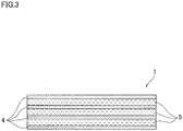
- FIG. 3 is a sectional view of the lining material sheet.
- the lining material sheet 1 is a sheet-like member, and is rolled into a tubular form, to be used as the lining material 1.
- the lining material 1 obtained by rolling the lining material sheet 1 into the tubular form is inserted into a tubular woven fabric 2.
- the lining material sheet 1 is formed of a plurality of layers which are: non-woven fabrics 4 of organic fibers such as polyester (e.g., spunbond non-woven fabrics) ; and woven glass roving fabrics 5 each made by weaving high-strength glass roving.
- the non-woven fabrics 4 and woven glass roving fabrics 5 are alternately laid on one another, and the layers are joined together by needle punching.
- the non-woven fabrics 4 are respectively laid on both sides of each woven glass roving fabric 5, and thus each woven glass roving fabric 5 is sandwiched by the non-woven fabrics 4.
- the lining material sheet 1 of this embodiment includes woven fabric made of glass yarns. This enhances its strength, and hence it is possible to decrease the overall thickness of the lining material 1.
- the woven fabric made of the glass yarns is particularly the woven glass roving fabric, and this further enhances the strength of the lining material 1.
- both ends of the lining material sheet 1 rolled into the tubular form i.e., the both ends in its circumferential direction are joined to each other by a hot melt adhesive 6 with the both ends overlapping each other.
- FIG. 4 is an enlarged view of an overlapping portion of FIG. 1 where the both ends of the lining material sheet overlap each other.
- the hot melt adhesive 6 is not applied to all over the surface of one of the ends of the lining material sheet 1, but is partially applied thereto, specifically to a plurality of (two in FIG. 4 ) elongate regions on the surface which regions are parallel to a longitudinal direction of the tubular form.
- the other end of the lining material sheet 1 is laid on the surface of the one end of the lining material sheet 1 on which surface the adhesive 6 has been applied, to join the both ends of the lining material sheet 1 to each other.
- the portion where both ends of the lining material sheet 1 overlap each other will be referred to as an "overlapping portion la".
- both ends of the lining material sheet 1 are temporarily joined merely to prevent the both ends from shifting relative to each other when the lining material 1 is inverted and inserted into the conduit P.
- the hot melt adhesive 6 is softened and thereby the joined both ends are released.
- the tubular woven fabric 2 shown in FIG. 1 is made by weaving polyester fibers, for example.
- An outer surface of the tubular woven fabric 2 is coated with a coating 3 of a thermoplastic resin such as polyethylene, polypropylene, nylon, or polyester, to impart air tightness to the tubular woven fabric 2.
- a coating 3 of a thermoplastic resin such as polyethylene, polypropylene, nylon, or polyester, to impart air tightness to the tubular woven fabric 2.
- the lining material 1 obtained by rolling the lining material sheet 1 into the tubular form is inserted, and thereby an outer surface of the lining material 1 is covered with the tubular woven fabric 2.
- the above-described lining material 1 is produced through the following processes, for example. First, the glass roving is woven using a plain weaving machine, to make the woven glass roving fabrics 5. Then, the woven glass roving fabrics 5 and the non-woven fabrics 4 are alternately laid on one another and joined together by needle punching, and this lamination is cut to form the lining material sheet 1 having a predetermined width. Thereafter, the lining material sheet 1 is rolled into the tubular form. After the hot melt adhesive 6 is applied to the surface of one of the both ends of the lining material sheet 1, the other end of the sheet is laid on the one end, to join the both ends. The thus produced tubular lining material 1 is inserted into the tubular woven fabric 2, and then the lining material 1 and the tubular woven fabric 2 are wholly impregnated with the liquid thermosetting resin.
- the lining material 1 into which the liquid thermosetting resin has been injected is squeezed using a nip roller.
- a liquid resin having a lower viscosity than that of generally used resins i.e., a liquid resin dripping at normal temperature
- the lining material 1 is conveyed to a higher position.
- the resin impregnation process is simplified. Note that, if the lining material 1 is conveyed after impregnated with the resin, the low-viscous liquid resin may drip. Therefore, it is preferable to conduct a viscosity increasing process (e.g., heating, cooling, or the like) depending on the type of the liquid resin to increase the viscosity, before the lining material 1 is conveyed.
- a viscosity increasing process e.g., heating, cooling, or the like
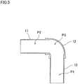
- FIG. 5 is a sectional view of a bending portion of the conduit to be repaired.
- the conduit P to be repaired in this embodiment is structured by coupling two straight pipes 10 and 11 using a bend pipe 12 (a 90 degree elbow in FIG. 5 ). That is, the conduit P includes a bending portion P3 between two straight pipe portions P1 and P2.
- the lining material 1 obtained by rolling the lining material sheet 1 into the tubular form is installed in the conduit P to be repaired (installation step). Then, the diameter of the lining material 1 installed in the conduit P is expanded with the both ends of the lining material sheet 1 circumferentially slid on each other (diameter expansion step). Further, in the above diameter expansion step, the lining material 1 is heated and pressurized from the inside thereof, to set the liquid thermosetting resin with which the lining material 1 has been impregnated while expanding the diameter of the lining material 1.
- FIG. 6 is a longitudinal sectional view of the conduit at the time of installing the lining material.
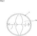
- FIG. 7 is a view of a leading end portion of an inverted portion of the lining material which is being installed, viewed from a front with respect to a direction in which the lining material proceeds.
- the tubular lining material 1 impregnated with the liquid thermosetting resin is installed in the conduit P while inverting the lining material 1 so as to be inside out by applying fluid pressure thereto (inversion method).
- one end portion of the long lining material 1 wound on a reel (not shown) is turned inside out and then the entire circumference of the inside-out one end portion is secured to an end of the conduit P.
- An inner surface of the inside-out portion is coated with the airtight coating 3.
- fluid pressure such as pressurized air is applied to the surface, which is coated with the coating 3, of the inside-out portion.
- the fluid pressure advances a leading end portion 1b of the inverted portion of the lining material 1 forward along the conduit P, and with this, the lining material 1 is unwound from the reel.
- the inversion of the lining material 1 proceeds continuously, and the lining material 1 is inverted to be inside out over its whole length.
- the fluid pressure advances the leading end portion 1b of the inverted portion of the lining material 1 along the conduit P, and therefore it is relatively easy to install the lining material 1 even though the conduit P has the bending portion P3.
- the both ends of the lining material sheet 1 are joined (temporarily joined) to each other by the hot melt adhesive 6, and this prevents the both ends from shifting relative to each other and thereby expanding the lining material 1 during the inside-out inversion of the lining material 1.
- FIG. 8 is a sectional view of the bending portion of the conduit after the installation step.
- FIG. 9 is a sectional view taken along a line IX-IX in FIG. 8 .
- FIG. 10 is an enlarged view of the overlapping portion of the lining material, encircled with an ellipse A in FIG. 9 .
- the lining material 1 is installed so that, in the bending portion P3, the overlapping portion la of the both ends of the lining material sheet 1 faces toward the outer curvature side of the bending portion P3, as shown in FIG. 9 .
- the lining material 1 is placed so that the overlapping portion la faces toward one of lateral sides of the conduit P (i.e., the side corresponding to the outer curvature side of the bending portion P3).
- the inversion of the lining material 1 is started after the above placement. Then, as shown in FIG.
- the overlapping portion la of the lining material 1 faces a portion of the inner surface of the bending portion P3 which portion is on the outer curvature side.
- the condition of the inner surface of the conduit P is checked using a television camera inserted into the conduit P.
- the direction of the outer curvature side of the bending portion P3 of the conduit P is also checked using the television camera.
- FIG. 11 is a sectional view of the bending portion of the conduit after the diameter expansion step.
- FIG. 12 is a sectional view taken along a line XII-XII in FIG. 11 .
- FIG. 13 is an enlarged view of the overlapping portion of the lining material, encircled with an ellipse B in FIG. 12 .
- the lining material 1 installed in the conduit P is pressurized from the inside while heated to the setting temperature of the liquid thermosetting resin (for example, 80 to 100 degrees Celsius) or higher. Thereby, the diameter of the lining material 1 is expanded, and the liquid thermosetting resin is set.
- the way to heat the lining material 1 and pressurize to the lining material 1 from the inside thereof is not particularly limited. However, for example, it is convenient to use a heating medium, to simultaneously conduct the diameter expansion of the lining material 1 and the setting of the liquid thermosetting resin, as described below.
- the tubular woven fabric 2 After the installation step (after inverted), the tubular woven fabric 2 is located inside the lining material 1, and the inner surface of the tubular woven fabric 2 is coated with the airtight coating 3. Therefore, by supplying a heating medium such as heated air or steam into the tubular woven fabric 2, the lining material 1 is pressurized from the inside thereof to expand its diameter, while heating the lining material 1.
- a heating medium such as heated air or steam
- the lining material 1 is heated to the setting temperature of the thermosetting resin (for example, 80 to 100 degrees Celsius).
- the hot melt adhesive 6 temporarily joining the both ends of the lining material sheet 1 is softened, and thereby its adhesion is decreased, which allows the both ends of the lining material sheet 1 to circumferentially slide on each other.
- the type of the hot melt adhesive 6 may be determined appropriately based on the setting temperature of the liquid thermosetting resin.
- the lining material 1 is pressurized from the inside thereof, and this causes the both ends of the lining material sheet 1 to circumferentially slide on each other, to increase the diameter of the lining material 1.
- the lining material 1 is pressed onto the inner surface of the conduit P to be brought into close contact with the inner surface, and in this state, the thermosetting resin is thermally set.
- the thermosetting resin is reinforced by the high-strength woven glass roving fabrics 5.
- the lining material 1 is installed so that, in the bending portion P3 of the conduit P, the overlapping portion la of the both ends of the lining material sheet 1 faces toward the outer curvature side of the bending portion P3, as shown in FIG. 9 . Therefore, when the diameter of the lining material 1 is expanded in the diameter expansion step, the both ends of the lining material sheet 1 circumferentially slide on each other, while the overlapping portion la faces toward the outer curvature side of the bending portion P3. This facilitates outward inflation of a portion of the lining material 1 which portion faces toward the outer curvature side. Consequently, as shown in FIGs.
- a gap between the lining material 1 and the inner surface of the conduit P is decreased in the bending portion P3, and it is more likely that the lining material 1 fits the inner surface of the conduit P over its entire circumference, also in the bending portion P3.
- the lining material 1 is inflated outward since the both ends of the lining material sheet 1 slide on each other widely. Therefore, the distance which the both ends slide in the bending portion P3 is larger than that in each of the straight pipe portions P1 and P2 of the conduit P. In other words, the size of the overlapping portion la of the lining material 1 in the bending portion P3 is smaller than that in each of the straight pipe portions P1 and P2.
- the present invention which enables the lining material 1 to be greatly inflated toward the outer curvature side of the bending portion P3, is effective particularly in such a case where the amount of curvature of the bending portion P3 is large.
- the inversion method is used in the above-described installation step in this embodiment, and therefore it is more likely that large tension is applied to the lining material 1 when the lining material 1 is inverted to be inside out. Furthermore, when the both ends of the lining material sheet 1 slide on each other to expand the diameter of the lining material 1 in the diameter expansion step, it is more likely that large friction is produced between the both ends. Such a large external force applied to a part of the lining material 1 is more likely to cause yarn slippage in the woven glass roving fabrics 5. However, in the lining material 1 of this embodiment, the non-woven fabrics 4 are laid on the woven glass roving fabrics 5 and they are joined together by needle punching.
- each non-woven fabric 4 has a structure in which long fibers are entangled. Therefore, when an external force is applied to the woven glass roving fabrics 5, the non-woven fabrics 4 joined to the woven glass roving fabrics 5 apply resistance to the glass yarns forming each woven glass roving fabric 5, to suppress shifting of the glass yarns, i.e., the yarn slippage in the woven glass roving fabrics 5.
- the non-woven fabrics 4 are laid on the woven glass roving fabrics 5, and this also prevents raveling out of the woven glass roving fabrics 5 at an edge.
- the non-woven fabrics 4 are respectively laid on the both sides of each woven glass roving fabric 5, and the non-woven fabrics 4 and the woven glass roving fabrics 5 are joined together by needle punching with each woven glass roving fabric 5 sandwiched by the two non-woven fabrics 4. This further suppresses the yarn slippage in the woven glass roving fabrics 5 and the raveling out at an edge.
Landscapes
- Engineering & Computer Science (AREA)
- General Engineering & Computer Science (AREA)
- Mechanical Engineering (AREA)
- Textile Engineering (AREA)
- Manufacturing & Machinery (AREA)
- Lining Or Joining Of Plastics Or The Like (AREA)
- Pipe Accessories (AREA)
- Laminated Bodies (AREA)
Claims (8)
- Verfahren zum Beschichten einer Leitung (P) mit einem gebogenen Teilbereich (P3), wobei das Verfahren Folgendes umfasst:einen Installationsschritt, bei welchem ein Beschichtungsmaterial in der Leitung (P) installiert wird, das durch Rollen eines Beschichtungsmaterialblattes (1) in eine rohrförmige Form erhalten wurde, wobei beide Enden des Beschichtungsmaterialblattes (1) in ihrer Umfangsrichtung umfangsmäßig miteinander überlappen; undeinen Durchmesseraufweitungsschritt, bei welchem ein Durchmesser des in der Leitung (P) installierten Beschichtungsmaterials aufgeweitet wird während die beiden Enden des Beschichtungsmaterialblattes (1) in Umfangsrichtung aneinander gleiten, dadurch gekennzeichnet, dass,in dem Installationsschritt das Beschichtungsmaterial derart installiert wird, dass ein Überlappungsteilbereich (1a), in welchem die beiden Enden des Beschichtungsmaterialblattes (1) einander überlappen, einer Außenkrümmungsseite des gebogenen Teilbereichs (P3) der Leitung (P) zugewandt ist.
- Verfahren nach Anspruch 1, wobei
das Beschichtungsmaterialblatt (1) ein aus Glasgarnen hergestelltes Gewebe umfasst. - Verfahren nach Anspruch 2, wobei
das aus Glasgarnen hergestellte Gewebe ein Gewebe (5) aus Glasrovings ist, bei welchem der Glasroving aus parallelen Glasgarnen hergestellt ist. - Verfahren nach Anspruch 2 oder 3, wobei
das Beschichtungsmaterialblatt (1) eine Struktur aufweist, bei welcher ein nicht gewebtes Textilerzeugnis (4) aus organischen Fasern auf das aus den Glasgarnen hergestellte Gewebe gelegt ist, und das nicht gewebte Textilerzeugnis (4) und das Gewebe durch Nadellochen miteinander verbunden sind. - Verfahren nach Anspruch 4, wobei
das nicht gewebte Textilerzeugnis (4) eine Vielzahl von nicht gewebten Textilerzeugnissen enthält und die nicht gewebten Textilerzeugnisse jeweils auf beide Seiten des aus den Glasgarnen hergestellten Gewebes gelegt sind. - Verfahren nach irgendeinem der Ansprüche 1 bis 5, wobei:das Beschichtungsmaterial mit einem flüssigen wärmeaushärtenden Harz imprägniert ist; undin dem Durchmesseraufweitungsschritt das Beschichtungsmaterial erhitzt und von seiner Innenseite aus mit Druck beaufschlagt wird, um das flüssige wärmeaushärtende Harz auszuhärten während der Durchmesser des Beschichtungsmaterials mit den beiden Enden des Beschichtungsmaterialblattes (1) aneinander gleitend aufgeweitet wird.
- Verfahren nach Anspruch 6, wobei:die beiden Enden des in die rohrförmige Form gerollten Beschichtungsmaterialblattes (1) mittels eines Schmelzklebstoffs (6) miteinander verbunden werden, wobei die beiden Enden einander überlappen; und
in dem Durchmesseraufweitungsschritt das Beschichtungsmaterial erhitzt und von seiner Innenseite aus mit Druck beaufschlagt wird, um die beiden von dem Schmelzklebstoff (6) verbundenen Enden zu lösen. - Verwendung eines Beschichtungsmaterials in dem Verfahren zum Beschichten einer Leitung (P) nach irgendeinem der Ansprüche 1 bis 7, wobei das Beschichtungsmaterial durch Rollen eines Beschichtungsmaterialblattes (1) in eine rohrförmige Form erhalten wird, und wobei das Beschichtungsmaterialblatt (1) umfasst:ein nicht gewebtes Textilerzeugnis (4) aus organischen Fasern und ein aus Glasgarnen hergestelltes Gewebe, die aufeinander gelegt und durch Nadellochen miteinander verbunden sind, wobeibeide Enden des Beschichtungsmaterialblattes (1) in ihrer Umfangsrichtung mittels eines Schmelzklebstoffes (6) mit den beiden Enden einander überlappend miteinander verbunden sind.
Applications Claiming Priority (1)
| Application Number | Priority Date | Filing Date | Title |
|---|---|---|---|
| PCT/JP2012/060021 WO2013153652A1 (ja) | 2012-04-12 | 2012-04-12 | 管路の内張り方法、及び、管路の内張り材 |
Publications (3)
| Publication Number | Publication Date |
|---|---|
| EP2839947A1 EP2839947A1 (de) | 2015-02-25 |
| EP2839947A4 EP2839947A4 (de) | 2016-06-08 |
| EP2839947B1 true EP2839947B1 (de) | 2018-01-10 |
Family
ID=49327258
Family Applications (1)
| Application Number | Title | Priority Date | Filing Date |
|---|---|---|---|
| EP12874221.0A Active EP2839947B1 (de) | 2012-04-12 | 2012-04-12 | Beschichtungsverfahren für eine leitung und verwendung eines beschichtungsmaterials bei diesem verfahren |
Country Status (9)
| Country | Link |
|---|---|
| US (1) | US9429265B2 (de) |
| EP (1) | EP2839947B1 (de) |
| KR (1) | KR101883031B1 (de) |
| CN (1) | CN104220237B (de) |
| AU (1) | AU2012376946A1 (de) |
| CA (1) | CA2870245C (de) |
| RU (1) | RU2597088C2 (de) |
| SG (1) | SG11201406522SA (de) |
| WO (1) | WO2013153652A1 (de) |
Families Citing this family (14)
| Publication number | Priority date | Publication date | Assignee | Title |
|---|---|---|---|---|
| JP6030937B2 (ja) * | 2012-12-07 | 2016-11-24 | 芦森工業株式会社 | 管路の内張り材、及び、管路の内張り方法 |
| US20160178108A1 (en) * | 2013-11-06 | 2016-06-23 | Mohammad Reza Ehsani | Repair and reinforcement of pressurized pipes |
| DE102015105668C5 (de) * | 2015-04-14 | 2020-07-09 | Cuylits Holding GmbH | Verbundschlauch zur Reparatur undichter Fluidleitungen, Verfahren zur Herstellung eines derartigen Verbundschlauches und Verfahren zur Reparatur undichter Fluidleitungen mit einem Verbundschlauch |
| US10428177B2 (en) | 2016-06-03 | 2019-10-01 | Sirrus, Inc. | Water absorbing or water soluble polymers, intermediate compounds, and methods thereof |
| US11125375B2 (en) | 2016-06-30 | 2021-09-21 | Sanexen Environmental Services Inc. | Tubular liner for rehabilitating underground and surface pipes and pipelines |
| US10914416B2 (en) * | 2016-07-01 | 2021-02-09 | Infrastructure Technologies, Llc. | Cured in place pipe system having integrated thermoplastic with improved melt-flow characteristics |
| RU2677016C2 (ru) * | 2017-01-20 | 2019-01-15 | Михаил Георгиевич Жданов | Способ ремонта напорных трубопроводов и плоская оболочка для его выполнения |
| US10969052B2 (en) * | 2018-02-15 | 2021-04-06 | Infrastructure Technologies, LLC | Pipe fittings having integrated thermoplastic with improved melt-flow characteristics for cured in place pipe systems and associated method of use |
| US10969051B2 (en) * | 2018-02-15 | 2021-04-06 | Infrastructure Tecnologies, LLC | Top hat liner having integrated thermoplastic with improved melt-flow characteristics for connection of main and lateral pipes in cured in place pipe systems and associated method of use |
| DE102018211893A1 (de) * | 2018-07-17 | 2020-01-23 | Bkp Berolina Polyester Gmbh & Co. Kg | Schlauchpaket zur Herstellung eines Schlauchliners sowie Verfahren und Vorrichtung zur Herstellung eines Schlauchliners aus dem Schlauchpaket |
| CN110939820B (zh) * | 2019-12-31 | 2021-08-20 | 南通大学 | 一种非开挖管道内衬法管道修复层连接方法 |
| AU2022203404A1 (en) * | 2021-05-19 | 2022-12-08 | Repiper Ab | Liner Arrangement For Inserting in a Pipe Structure, and Method For Relining a Pipe Structure |
| CN113635571A (zh) * | 2021-09-08 | 2021-11-12 | 广西电网有限责任公司电力科学研究院 | 一种玄武岩纤维增强复合绝缘横担装置及其制备方法 |
| WO2023126529A2 (de) * | 2021-12-30 | 2023-07-06 | Relineeurope Gmbh | Textil mit zwei matrixbildenden komponenten |
Family Cites Families (37)
| Publication number | Priority date | Publication date | Assignee | Title |
|---|---|---|---|---|
| JPS601178B2 (ja) | 1979-07-03 | 1985-01-12 | 東京瓦斯株式会社 | 管路の内張り基材 |
| CH656093A5 (fr) | 1982-01-21 | 1986-06-13 | Coopetanche Sa | Materiau composite compact souple. |
| JPS61143129A (ja) | 1984-12-18 | 1986-06-30 | 芦森工業株式会社 | 管路の内張り材 |
| GB9006154D0 (en) | 1990-03-19 | 1990-05-16 | Insituform Group Ltd | Improvements relating to lining materials for pipelines and passageways and to pipes produced from such materials |
| JP2736368B2 (ja) * | 1990-04-10 | 1998-04-02 | 芦森工業株式会社 | 管路の内張り材及び管路の内張り方法 |
| CA2072173C (en) * | 1991-06-24 | 2002-06-04 | Takayoshi Imoto | Lining material for pipe lines and a process for providing pipe lines therewith |
| JP3165227B2 (ja) | 1992-04-04 | 2001-05-14 | 芦森工業株式会社 | 管路の内張り材 |
| JP3051277B2 (ja) | 1993-02-24 | 2000-06-12 | 東京都 | 硬化性樹脂管 |
| US5950682A (en) | 1994-08-19 | 1999-09-14 | Lmk Enterprises, Inc. | Apparatus and method for repairing the junction of a sewer main line and lateral |
| US5861116A (en) | 1994-08-31 | 1999-01-19 | Plastic Innovations, Inc. | Process for installing a pipe liner |
| US5836357A (en) * | 1995-10-26 | 1998-11-17 | Bay Mills Ltd. | Pressure-expandable conduit liner |
| TW347455B (en) * | 1995-11-09 | 1998-12-11 | Link Pipe Inc | Conduit lining system and method of lining a conduit |
| JP3784901B2 (ja) | 1996-11-22 | 2006-06-14 | 旭テック株式会社 | 排水管等の管路更生装置 |
| RU2145028C1 (ru) * | 1997-04-10 | 2000-01-27 | Сибирский научно-исследовательский институт гидротехники и мелиорации | Способ оклейки внутренней поверхности трубопровода тканью |
| FR2765619B1 (fr) * | 1997-07-01 | 2000-10-06 | Schlumberger Cie Dowell | Procede et dispositif pour la completion de puits pour la production d'hydrocarbures ou analogues |
| EP0899420A1 (de) * | 1997-08-27 | 1999-03-03 | Shell Internationale Researchmaatschappij B.V. | Verfahren zum Installieren einer zusammengerollten biegsamen Platte entlang der Innenfläche einer Flüssigkeitsleitung |
| JP2000127242A (ja) | 1998-10-26 | 2000-05-09 | Shonan Gosei Jushi Seisakusho:Kk | 管ライニング材の製造方法 |
| JP2001030354A (ja) | 1999-07-16 | 2001-02-06 | Osaka Gas Co Ltd | 管内ライニング工法 |
| JP2001047512A (ja) | 1999-08-06 | 2001-02-20 | Shonan Gosei Jushi Seisakusho:Kk | 管ライニング工法 |
| JP4367734B2 (ja) * | 1999-10-18 | 2009-11-18 | 芦森工業株式会社 | 管路の内張り材 |
| JP2001129882A (ja) * | 1999-11-04 | 2001-05-15 | Shonan Gosei Jushi Seisakusho:Kk | 管ライニング材及び管ライニング工法 |
| JP2001219471A (ja) | 2000-02-14 | 2001-08-14 | Shonan Gosei Jushi Seisakusho:Kk | 管ライニング材とその製造方法及び管ライニング工法 |
| JP4288318B2 (ja) * | 2002-02-08 | 2009-07-01 | 旭テック環境ソリューション株式会社 | 地中管補修材 |
| JP4070575B2 (ja) | 2002-10-22 | 2008-04-02 | 大阪瓦斯株式会社 | 既設管の補修工法 |
| JP4989203B2 (ja) | 2006-12-04 | 2012-08-01 | 株式会社湘南合成樹脂製作所 | ライニング材及び管路ライニング工法 |
| JP2008201062A (ja) | 2007-02-22 | 2008-09-04 | Airec Engineering Corp | 管路補修方法 |
| KR100813860B1 (ko) | 2007-12-20 | 2008-03-17 | 동도기공 주식회사 | 노후 수도관 내의 비굴착 갱생용 곡관부위 폴리에틸렌라이닝의 주름제거 방법 및 그 장치 |
| JP2010162749A (ja) | 2009-01-15 | 2010-07-29 | Kazu Chemical:Kk | 管ライニング材の製造方法 |
| JP5495250B2 (ja) * | 2009-05-08 | 2014-05-21 | 株式会社湘南合成樹脂製作所 | 管ライニング材及び管路ライニング工法 |
| JP2011042164A (ja) | 2009-07-24 | 2011-03-03 | Sekisui Chem Co Ltd | 既設管の更生工法 |
| JP2011104786A (ja) | 2009-11-12 | 2011-06-02 | Sekisui Chem Co Ltd | ライニング材 |
| CA2786992A1 (en) | 2010-04-02 | 2011-10-13 | Sekisui Chemicals Co., Ltd. | Lining material for rehabilitating host pipe and method for rehabilitating host pipe using same |
| JP2012006273A (ja) | 2010-06-25 | 2012-01-12 | Ashimori Industry Co Ltd | 管路の内張り材及び管路の内張り方法 |
| JP5926483B2 (ja) | 2010-10-15 | 2016-05-25 | 芦森工業株式会社 | 管路の内張り材及びこれを用いた管路の内張り方法 |
| US20120199276A1 (en) * | 2011-02-07 | 2012-08-09 | Spiniello Companies | Tubular Liner for Underground Pipes and Method of Installing Tubular Liner |
| JP2014517220A (ja) * | 2011-04-18 | 2014-07-17 | ファイフ カンパニー,エルエルシー | 保護用拡張ライナおよび既存パイプの強化 |
| US9163771B1 (en) * | 2015-01-26 | 2015-10-20 | Rosetta Higman | Conduit repair system |
-
2012
- 2012-04-12 US US14/391,968 patent/US9429265B2/en active Active
- 2012-04-12 KR KR1020147031518A patent/KR101883031B1/ko active Active
- 2012-04-12 SG SG11201406522SA patent/SG11201406522SA/en unknown
- 2012-04-12 EP EP12874221.0A patent/EP2839947B1/de active Active
- 2012-04-12 CA CA2870245A patent/CA2870245C/en active Active
- 2012-04-12 RU RU2014145025/05A patent/RU2597088C2/ru active
- 2012-04-12 WO PCT/JP2012/060021 patent/WO2013153652A1/ja not_active Ceased
- 2012-04-12 AU AU2012376946A patent/AU2012376946A1/en not_active Abandoned
- 2012-04-12 CN CN201280072304.8A patent/CN104220237B/zh active Active
Non-Patent Citations (1)
| Title |
|---|
| None * |
Also Published As
| Publication number | Publication date |
|---|---|
| KR20150003305A (ko) | 2015-01-08 |
| US9429265B2 (en) | 2016-08-30 |
| EP2839947A4 (de) | 2016-06-08 |
| KR101883031B1 (ko) | 2018-07-27 |
| CN104220237A (zh) | 2014-12-17 |
| RU2597088C2 (ru) | 2016-09-10 |
| RU2014145025A (ru) | 2016-06-10 |
| CA2870245A1 (en) | 2013-10-17 |
| EP2839947A1 (de) | 2015-02-25 |
| HK1205060A1 (en) | 2015-12-11 |
| CN104220237B (zh) | 2017-03-01 |
| AU2012376946A1 (en) | 2014-11-06 |
| WO2013153652A1 (ja) | 2013-10-17 |
| SG11201406522SA (en) | 2014-11-27 |
| US20150068632A1 (en) | 2015-03-12 |
| CA2870245C (en) | 2020-02-25 |
Similar Documents
| Publication | Publication Date | Title |
|---|---|---|
| EP2839947B1 (de) | Beschichtungsverfahren für eine leitung und verwendung eines beschichtungsmaterials bei diesem verfahren | |
| AU2013355697B2 (en) | Lining Material for Conduit and Lining Method for Conduit | |
| JP6009573B2 (ja) | パイプの建造 | |
| JP4367734B2 (ja) | 管路の内張り材 | |
| JP5926483B2 (ja) | 管路の内張り材及びこれを用いた管路の内張り方法 | |
| JP6975550B2 (ja) | 管路のライニング材 | |
| TWI547663B (zh) | Pipe lining method and piping lining material | |
| JP5438499B2 (ja) | 管路の内張り材 | |
| JP6878135B2 (ja) | 管路のライニング材およびその使用方法 | |
| HK1205060B (en) | Lining method for conduit and lining material for conduit | |
| JP2012006273A (ja) | 管路の内張り材及び管路の内張り方法 | |
| JP2018192799A (ja) | パイプの建造 | |
| JP5438497B2 (ja) | 内張り材の筒状内挿材 | |
| HK1213223B (en) | Pipe lining and method for lining pipe | |
| JP6552188B2 (ja) | 複合管及びその製造方法 | |
| JP2017081063A (ja) | 管用内張り材の反転方法及び管用内張り材 |
Legal Events
| Date | Code | Title | Description |
|---|---|---|---|
| PUAI | Public reference made under article 153(3) epc to a published international application that has entered the european phase |
Free format text: ORIGINAL CODE: 0009012 |
|
| 17P | Request for examination filed |
Effective date: 20141013 |
|
| AK | Designated contracting states |
Kind code of ref document: A1 Designated state(s): AL AT BE BG CH CY CZ DE DK EE ES FI FR GB GR HR HU IE IS IT LI LT LU LV MC MK MT NL NO PL PT RO RS SE SI SK SM TR |
|
| AX | Request for extension of the european patent |
Extension state: BA ME |
|
| DAX | Request for extension of the european patent (deleted) | ||
| RIC1 | Information provided on ipc code assigned before grant |
Ipc: F16L 55/165 20060101ALI20160115BHEP Ipc: B32B 5/06 20060101ALI20160115BHEP Ipc: B32B 5/02 20060101ALI20160115BHEP Ipc: B29L 9/00 20060101ALI20160115BHEP Ipc: B32B 1/08 20060101ALI20160115BHEP Ipc: B29C 63/34 20060101AFI20160115BHEP Ipc: B32B 5/26 20060101ALI20160115BHEP Ipc: B32B 3/02 20060101ALI20160115BHEP Ipc: B29L 23/00 20060101ALN20160115BHEP |
|
| RA4 | Supplementary search report drawn up and despatched (corrected) |
Effective date: 20160511 |
|
| RIC1 | Information provided on ipc code assigned before grant |
Ipc: B32B 5/02 20060101ALI20160504BHEP Ipc: B32B 1/08 20060101ALI20160504BHEP Ipc: B32B 5/06 20060101ALI20160504BHEP Ipc: B32B 3/02 20060101ALI20160504BHEP Ipc: B32B 5/26 20060101ALI20160504BHEP Ipc: B29L 9/00 20060101ALI20160504BHEP Ipc: F16L 55/165 20060101ALI20160504BHEP Ipc: B29C 63/34 20060101AFI20160504BHEP Ipc: B29L 23/00 20060101ALN20160504BHEP |
|
| GRAP | Despatch of communication of intention to grant a patent |
Free format text: ORIGINAL CODE: EPIDOSNIGR1 |
|
| RIC1 | Information provided on ipc code assigned before grant |
Ipc: B29L 23/00 20060101ALN20170706BHEP Ipc: F16L 55/165 20060101ALI20170706BHEP Ipc: B29C 63/34 20060101AFI20170706BHEP Ipc: B29L 9/00 20060101ALI20170706BHEP Ipc: B32B 5/02 20060101ALI20170706BHEP Ipc: B32B 1/08 20060101ALI20170706BHEP Ipc: B32B 5/26 20060101ALI20170706BHEP Ipc: B32B 5/06 20060101ALI20170706BHEP Ipc: B32B 3/02 20060101ALI20170706BHEP |
|
| INTG | Intention to grant announced |
Effective date: 20170801 |
|
| GRAS | Grant fee paid |
Free format text: ORIGINAL CODE: EPIDOSNIGR3 |
|
| GRAA | (expected) grant |
Free format text: ORIGINAL CODE: 0009210 |
|
| AK | Designated contracting states |
Kind code of ref document: B1 Designated state(s): AL AT BE BG CH CY CZ DE DK EE ES FI FR GB GR HR HU IE IS IT LI LT LU LV MC MK MT NL NO PL PT RO RS SE SI SK SM TR |
|
| REG | Reference to a national code |
Ref country code: CH Ref legal event code: EP Ref country code: AT Ref legal event code: REF Ref document number: 961903 Country of ref document: AT Kind code of ref document: T Effective date: 20180115 |
|
| REG | Reference to a national code |
Ref country code: IE Ref legal event code: FG4D |
|
| REG | Reference to a national code |
Ref country code: DE Ref legal event code: R096 Ref document number: 602012042055 Country of ref document: DE |
|
| REG | Reference to a national code |
Ref country code: FR Ref legal event code: PLFP Year of fee payment: 7 |
|
| REG | Reference to a national code |
Ref country code: NL Ref legal event code: MP Effective date: 20180110 |
|
| REG | Reference to a national code |
Ref country code: AT Ref legal event code: MK05 Ref document number: 961903 Country of ref document: AT Kind code of ref document: T Effective date: 20180110 |
|
| PG25 | Lapsed in a contracting state [announced via postgrant information from national office to epo] |
Ref country code: NL Free format text: LAPSE BECAUSE OF FAILURE TO SUBMIT A TRANSLATION OF THE DESCRIPTION OR TO PAY THE FEE WITHIN THE PRESCRIBED TIME-LIMIT Effective date: 20180110 |
|
| PG25 | Lapsed in a contracting state [announced via postgrant information from national office to epo] |
Ref country code: LT Free format text: LAPSE BECAUSE OF FAILURE TO SUBMIT A TRANSLATION OF THE DESCRIPTION OR TO PAY THE FEE WITHIN THE PRESCRIBED TIME-LIMIT Effective date: 20180110 Ref country code: CY Free format text: LAPSE BECAUSE OF FAILURE TO SUBMIT A TRANSLATION OF THE DESCRIPTION OR TO PAY THE FEE WITHIN THE PRESCRIBED TIME-LIMIT Effective date: 20180110 Ref country code: HR Free format text: LAPSE BECAUSE OF FAILURE TO SUBMIT A TRANSLATION OF THE DESCRIPTION OR TO PAY THE FEE WITHIN THE PRESCRIBED TIME-LIMIT Effective date: 20180110 Ref country code: FI Free format text: LAPSE BECAUSE OF FAILURE TO SUBMIT A TRANSLATION OF THE DESCRIPTION OR TO PAY THE FEE WITHIN THE PRESCRIBED TIME-LIMIT Effective date: 20180110 Ref country code: NO Free format text: LAPSE BECAUSE OF FAILURE TO SUBMIT A TRANSLATION OF THE DESCRIPTION OR TO PAY THE FEE WITHIN THE PRESCRIBED TIME-LIMIT Effective date: 20180410 Ref country code: ES Free format text: LAPSE BECAUSE OF FAILURE TO SUBMIT A TRANSLATION OF THE DESCRIPTION OR TO PAY THE FEE WITHIN THE PRESCRIBED TIME-LIMIT Effective date: 20180110 |
|
| PG25 | Lapsed in a contracting state [announced via postgrant information from national office to epo] |
Ref country code: SE Free format text: LAPSE BECAUSE OF FAILURE TO SUBMIT A TRANSLATION OF THE DESCRIPTION OR TO PAY THE FEE WITHIN THE PRESCRIBED TIME-LIMIT Effective date: 20180110 Ref country code: LV Free format text: LAPSE BECAUSE OF FAILURE TO SUBMIT A TRANSLATION OF THE DESCRIPTION OR TO PAY THE FEE WITHIN THE PRESCRIBED TIME-LIMIT Effective date: 20180110 Ref country code: RS Free format text: LAPSE BECAUSE OF FAILURE TO SUBMIT A TRANSLATION OF THE DESCRIPTION OR TO PAY THE FEE WITHIN THE PRESCRIBED TIME-LIMIT Effective date: 20180110 Ref country code: PL Free format text: LAPSE BECAUSE OF FAILURE TO SUBMIT A TRANSLATION OF THE DESCRIPTION OR TO PAY THE FEE WITHIN THE PRESCRIBED TIME-LIMIT Effective date: 20180110 Ref country code: AT Free format text: LAPSE BECAUSE OF FAILURE TO SUBMIT A TRANSLATION OF THE DESCRIPTION OR TO PAY THE FEE WITHIN THE PRESCRIBED TIME-LIMIT Effective date: 20180110 Ref country code: GR Free format text: LAPSE BECAUSE OF FAILURE TO SUBMIT A TRANSLATION OF THE DESCRIPTION OR TO PAY THE FEE WITHIN THE PRESCRIBED TIME-LIMIT Effective date: 20180411 Ref country code: BG Free format text: LAPSE BECAUSE OF FAILURE TO SUBMIT A TRANSLATION OF THE DESCRIPTION OR TO PAY THE FEE WITHIN THE PRESCRIBED TIME-LIMIT Effective date: 20180410 Ref country code: IS Free format text: LAPSE BECAUSE OF FAILURE TO SUBMIT A TRANSLATION OF THE DESCRIPTION OR TO PAY THE FEE WITHIN THE PRESCRIBED TIME-LIMIT Effective date: 20180510 |
|
| REG | Reference to a national code |
Ref country code: DE Ref legal event code: R097 Ref document number: 602012042055 Country of ref document: DE |
|
| PG25 | Lapsed in a contracting state [announced via postgrant information from national office to epo] |
Ref country code: AL Free format text: LAPSE BECAUSE OF FAILURE TO SUBMIT A TRANSLATION OF THE DESCRIPTION OR TO PAY THE FEE WITHIN THE PRESCRIBED TIME-LIMIT Effective date: 20180110 Ref country code: IT Free format text: LAPSE BECAUSE OF FAILURE TO SUBMIT A TRANSLATION OF THE DESCRIPTION OR TO PAY THE FEE WITHIN THE PRESCRIBED TIME-LIMIT Effective date: 20180110 Ref country code: EE Free format text: LAPSE BECAUSE OF FAILURE TO SUBMIT A TRANSLATION OF THE DESCRIPTION OR TO PAY THE FEE WITHIN THE PRESCRIBED TIME-LIMIT Effective date: 20180110 Ref country code: RO Free format text: LAPSE BECAUSE OF FAILURE TO SUBMIT A TRANSLATION OF THE DESCRIPTION OR TO PAY THE FEE WITHIN THE PRESCRIBED TIME-LIMIT Effective date: 20180110 |
|
| PLBE | No opposition filed within time limit |
Free format text: ORIGINAL CODE: 0009261 |
|
| STAA | Information on the status of an ep patent application or granted ep patent |
Free format text: STATUS: NO OPPOSITION FILED WITHIN TIME LIMIT |
|
| PG25 | Lapsed in a contracting state [announced via postgrant information from national office to epo] |
Ref country code: SK Free format text: LAPSE BECAUSE OF FAILURE TO SUBMIT A TRANSLATION OF THE DESCRIPTION OR TO PAY THE FEE WITHIN THE PRESCRIBED TIME-LIMIT Effective date: 20180110 Ref country code: CZ Free format text: LAPSE BECAUSE OF FAILURE TO SUBMIT A TRANSLATION OF THE DESCRIPTION OR TO PAY THE FEE WITHIN THE PRESCRIBED TIME-LIMIT Effective date: 20180110 Ref country code: MC Free format text: LAPSE BECAUSE OF FAILURE TO SUBMIT A TRANSLATION OF THE DESCRIPTION OR TO PAY THE FEE WITHIN THE PRESCRIBED TIME-LIMIT Effective date: 20180110 Ref country code: DK Free format text: LAPSE BECAUSE OF FAILURE TO SUBMIT A TRANSLATION OF THE DESCRIPTION OR TO PAY THE FEE WITHIN THE PRESCRIBED TIME-LIMIT Effective date: 20180110 Ref country code: SM Free format text: LAPSE BECAUSE OF FAILURE TO SUBMIT A TRANSLATION OF THE DESCRIPTION OR TO PAY THE FEE WITHIN THE PRESCRIBED TIME-LIMIT Effective date: 20180110 |
|
| REG | Reference to a national code |
Ref country code: CH Ref legal event code: PL |
|
| 26N | No opposition filed |
Effective date: 20181011 |
|
| REG | Reference to a national code |
Ref country code: BE Ref legal event code: MM Effective date: 20180430 |
|
| REG | Reference to a national code |
Ref country code: IE Ref legal event code: MM4A |
|
| PG25 | Lapsed in a contracting state [announced via postgrant information from national office to epo] |
Ref country code: LU Free format text: LAPSE BECAUSE OF NON-PAYMENT OF DUE FEES Effective date: 20180412 |
|
| PG25 | Lapsed in a contracting state [announced via postgrant information from national office to epo] |
Ref country code: CH Free format text: LAPSE BECAUSE OF NON-PAYMENT OF DUE FEES Effective date: 20180430 Ref country code: SI Free format text: LAPSE BECAUSE OF FAILURE TO SUBMIT A TRANSLATION OF THE DESCRIPTION OR TO PAY THE FEE WITHIN THE PRESCRIBED TIME-LIMIT Effective date: 20180110 Ref country code: LI Free format text: LAPSE BECAUSE OF NON-PAYMENT OF DUE FEES Effective date: 20180430 Ref country code: BE Free format text: LAPSE BECAUSE OF NON-PAYMENT OF DUE FEES Effective date: 20180430 |
|
| PG25 | Lapsed in a contracting state [announced via postgrant information from national office to epo] |
Ref country code: IE Free format text: LAPSE BECAUSE OF NON-PAYMENT OF DUE FEES Effective date: 20180412 |
|
| PG25 | Lapsed in a contracting state [announced via postgrant information from national office to epo] |
Ref country code: MT Free format text: LAPSE BECAUSE OF NON-PAYMENT OF DUE FEES Effective date: 20180412 |
|
| PG25 | Lapsed in a contracting state [announced via postgrant information from national office to epo] |
Ref country code: TR Free format text: LAPSE BECAUSE OF FAILURE TO SUBMIT A TRANSLATION OF THE DESCRIPTION OR TO PAY THE FEE WITHIN THE PRESCRIBED TIME-LIMIT Effective date: 20180110 |
|
| PG25 | Lapsed in a contracting state [announced via postgrant information from national office to epo] |
Ref country code: HU Free format text: LAPSE BECAUSE OF FAILURE TO SUBMIT A TRANSLATION OF THE DESCRIPTION OR TO PAY THE FEE WITHIN THE PRESCRIBED TIME-LIMIT; INVALID AB INITIO Effective date: 20120412 Ref country code: PT Free format text: LAPSE BECAUSE OF FAILURE TO SUBMIT A TRANSLATION OF THE DESCRIPTION OR TO PAY THE FEE WITHIN THE PRESCRIBED TIME-LIMIT Effective date: 20180110 |
|
| PG25 | Lapsed in a contracting state [announced via postgrant information from national office to epo] |
Ref country code: MK Free format text: LAPSE BECAUSE OF NON-PAYMENT OF DUE FEES Effective date: 20180110 |
|
| P01 | Opt-out of the competence of the unified patent court (upc) registered |
Effective date: 20230428 |
|
| PGFP | Annual fee paid to national office [announced via postgrant information from national office to epo] |
Ref country code: DE Payment date: 20250305 Year of fee payment: 14 |
|
| PGFP | Annual fee paid to national office [announced via postgrant information from national office to epo] |
Ref country code: GB Payment date: 20260313 Year of fee payment: 15 |
|
| PGFP | Annual fee paid to national office [announced via postgrant information from national office to epo] |
Ref country code: FR Payment date: 20260309 Year of fee payment: 15 |