EP2839980A1 - Aufwickelbare Blende - Google Patents
Aufwickelbare Blende Download PDFInfo
- Publication number
- EP2839980A1 EP2839980A1 EP13187983.5A EP13187983A EP2839980A1 EP 2839980 A1 EP2839980 A1 EP 2839980A1 EP 13187983 A EP13187983 A EP 13187983A EP 2839980 A1 EP2839980 A1 EP 2839980A1
- Authority
- EP
- European Patent Office
- Prior art keywords
- shade
- coilable
- rotating member
- coiling
- seat
- Prior art date
- Legal status (The legal status is an assumption and is not a legal conclusion. Google has not performed a legal analysis and makes no representation as to the accuracy of the status listed.)
- Withdrawn
Links
- 239000000872 buffer Substances 0.000 claims abstract description 15
- 230000008878 coupling Effects 0.000 claims description 8
- 238000010168 coupling process Methods 0.000 claims description 8
- 238000005859 coupling reaction Methods 0.000 claims description 8
- 229920002379 silicone rubber Polymers 0.000 claims description 3
- 230000037431 insertion Effects 0.000 claims 1
- 238000003780 insertion Methods 0.000 claims 1
- 230000003139 buffering effect Effects 0.000 description 14
- 230000000694 effects Effects 0.000 description 2
- 238000005034 decoration Methods 0.000 description 1
- 229920001971 elastomer Polymers 0.000 description 1
- 230000004048 modification Effects 0.000 description 1
- 238000012986 modification Methods 0.000 description 1
- 230000000717 retained effect Effects 0.000 description 1
- 210000002268 wool Anatomy 0.000 description 1
Images


Classifications
-
- E—FIXED CONSTRUCTIONS
- E06—DOORS, WINDOWS, SHUTTERS, OR ROLLER BLINDS IN GENERAL; LADDERS
- E06B—FIXED OR MOVABLE CLOSURES FOR OPENINGS IN BUILDINGS, VEHICLES, FENCES OR LIKE ENCLOSURES IN GENERAL, e.g. DOORS, WINDOWS, BLINDS, GATES
- E06B9/00—Screening or protective devices for wall or similar openings, with or without operating or securing mechanisms; Closures of similar construction
- E06B9/56—Operating, guiding or securing devices or arrangements for roll-type closures; Spring drums; Tape drums; Counterweighting arrangements therefor
- E06B9/60—Spring drums operated only by closure members
-
- B—PERFORMING OPERATIONS; TRANSPORTING
- B60—VEHICLES IN GENERAL
- B60J—WINDOWS, WINDSCREENS, NON-FIXED ROOFS, DOORS, OR SIMILAR DEVICES FOR VEHICLES; REMOVABLE EXTERNAL PROTECTIVE COVERINGS SPECIALLY ADAPTED FOR VEHICLES
- B60J1/00—Windows; Windscreens; Accessories therefor
- B60J1/20—Accessories, e.g. wind deflectors, blinds
- B60J1/2011—Blinds; curtains or screens reducing heat or light intensity
- B60J1/2013—Roller blinds
- B60J1/2033—Roller blinds characterised by the spring motor
-
- B—PERFORMING OPERATIONS; TRANSPORTING
- B60—VEHICLES IN GENERAL
- B60J—WINDOWS, WINDSCREENS, NON-FIXED ROOFS, DOORS, OR SIMILAR DEVICES FOR VEHICLES; REMOVABLE EXTERNAL PROTECTIVE COVERINGS SPECIALLY ADAPTED FOR VEHICLES
- B60J1/00—Windows; Windscreens; Accessories therefor
- B60J1/20—Accessories, e.g. wind deflectors, blinds
- B60J1/2011—Blinds; curtains or screens reducing heat or light intensity
- B60J1/2013—Roller blinds
- B60J1/2036—Roller blinds characterised by structural elements
- B60J1/205—Winding tubes, e.g. telescopic tubes or conically shaped tubes
-
- E—FIXED CONSTRUCTIONS
- E06—DOORS, WINDOWS, SHUTTERS, OR ROLLER BLINDS IN GENERAL; LADDERS
- E06B—FIXED OR MOVABLE CLOSURES FOR OPENINGS IN BUILDINGS, VEHICLES, FENCES OR LIKE ENCLOSURES IN GENERAL, e.g. DOORS, WINDOWS, BLINDS, GATES
- E06B9/00—Screening or protective devices for wall or similar openings, with or without operating or securing mechanisms; Closures of similar construction
- E06B9/24—Screens or other constructions affording protection against light, especially against sunshine; Similar screens for privacy or appearance; Slat blinds
- E06B9/40—Roller blinds
- E06B9/42—Parts or details of roller blinds, e.g. suspension devices, blind boxes
- E06B9/50—Bearings specially adapted therefor
-
- E—FIXED CONSTRUCTIONS
- E06—DOORS, WINDOWS, SHUTTERS, OR ROLLER BLINDS IN GENERAL; LADDERS
- E06B—FIXED OR MOVABLE CLOSURES FOR OPENINGS IN BUILDINGS, VEHICLES, FENCES OR LIKE ENCLOSURES IN GENERAL, e.g. DOORS, WINDOWS, BLINDS, GATES
- E06B9/00—Screening or protective devices for wall or similar openings, with or without operating or securing mechanisms; Closures of similar construction
- E06B9/56—Operating, guiding or securing devices or arrangements for roll-type closures; Spring drums; Tape drums; Counterweighting arrangements therefor
- E06B9/80—Safety measures against dropping or unauthorised opening; Braking or immobilising devices; Devices for limiting unrolling
- E06B9/82—Safety measures against dropping or unauthorised opening; Braking or immobilising devices; Devices for limiting unrolling automatic
- E06B9/90—Safety measures against dropping or unauthorised opening; Braking or immobilising devices; Devices for limiting unrolling automatic for immobilising the closure member in various chosen positions
-
- E—FIXED CONSTRUCTIONS
- E06—DOORS, WINDOWS, SHUTTERS, OR ROLLER BLINDS IN GENERAL; LADDERS
- E06B—FIXED OR MOVABLE CLOSURES FOR OPENINGS IN BUILDINGS, VEHICLES, FENCES OR LIKE ENCLOSURES IN GENERAL, e.g. DOORS, WINDOWS, BLINDS, GATES
- E06B9/00—Screening or protective devices for wall or similar openings, with or without operating or securing mechanisms; Closures of similar construction
- E06B9/56—Operating, guiding or securing devices or arrangements for roll-type closures; Spring drums; Tape drums; Counterweighting arrangements therefor
- E06B9/80—Safety measures against dropping or unauthorised opening; Braking or immobilising devices; Devices for limiting unrolling
- E06B2009/807—Brakes preventing fast screen movement
Definitions
- the present invention relates to a coilable shade and, more particularly, to a coilable shade including a soft ring rubber to drive a rotating member to change a position of a track in the rotating member for controlling unfolding, coiling, and positioning of a shade as well as increasing the rotational frictional force of the rotating member and providing the buffering effect while coiling the shade.
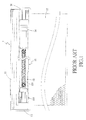
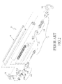
- FIGS. 1-3 show a conventional coilable shade 1 including a main frame 11, a coiling device 12, a pull/coil device 13 mounted to a left side of the main frame 11, a hydraulic buffering device 14 mounted to a right side of the main frame 11, and left and right fixed seats 15 and 16.
- a coiling spring 131 at a side of the pull/coil device 13 is tensioned and rotates freely.
- the rotating device 132 includes a rotating member 133 and a sleeve 134.
- Two friction pads 135 made of wool felt are mounted between the rotating member 133 and the sleeve 134 and spaced from each other. If the frictional force of the friction pads 135 is insufficient, the shade 17 coils rapidly and causes noise.
- the hydraulic buffering device 14 reduces the coiling speed of the shade 17, providing a buffering effect.
- the coilable shade 1 has the following disadvantages while coiling the shade 17:
- An objective of the present invention is to provide a coilable shade to mitigate and/or obviate the above disadvantages including rapid coiling of the shade, large volume, and high costs resulting from insufficient frictional force of frictional pads that fails to position the shade in a desired location and resulting from the hydraulic buffering device required for buffering the shade.
- a coilable shade including a main frame having left and right sides.
- a left fixed seat is mounted to the left side of the main frame.
- a right fixed seat is mounted to the right side of the main frame.
- a cap is rotatably mounted to the right fixed seat.
- a coiling device includes a drum having an end in which the cap is securely mounted, a spring received in the drum and including a first end and a second end, a shaft extending through the spring and including a first end and a second end, and a positioning seat. The first end of the shaft extends through the positioning seat.
- the first end of the coiling spring is fixed to the positioning seat.
- a control device is mounted to the left fixed seat.
- the second end of the coiling spring is fixed to the control device.
- the control device is received in the drum.
- a shade is coilable around the drum of the coiling device.
- the control device includes a jacket, a rotating unit mounted in an end of the jacket, a positioning rod rotatably coupled to the rotating unit and fixed to the left fixed seat, and a connecting seat mounted in the other end of the jacket.
- the shaft extends through the connecting seat.
- the other end of the jacket engages with a side of the coiling device.
- a fastener extends through an outer periphery of the jacket.
- the rotating unit includes a rotating member having a track and a guiding block in the track. The fastener is slideable along the track to control movement of the rotating member to control unfolding, coiling, and positioning of the shade.
- the rotating unit further includes a sleeve received in the rotating member.
- the sleeve includes an outer periphery having at least one annular groove. At least one soft ring buffer is received in the at least one annular groove and contacts an inner periphery of the rotating member.
- the at least one soft ring buffer of the control device can drive the rotating member to change the position of the track for unfolding, coiling, and positioning of the shade. Furthermore, the rotational friction force of the rotating member and the buffering effect during coiling of the shade can be increased, allowing easy operation and easy adjustment.
- the overall outer diameter of the control device according to the present invention is as small as 1.5 cm after assembly, which is not only suitable for coilable shades on doors and windows but also suitable for small shades used on doors of automobiles, providing a wider application.
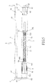
- a coilable shade 2 includes a main frame 3 having two upwardly extending abutment sides 31 and 32, with the abutment sides 31 and 32 opposite to each other.
- a channel 33 is defined between two inner faces of the abutment sides 31 and 32.
- the coilable shade 2 further includes left and right fixed seats 4 and 5 opposite to each other and respectively mounted to left and right sides of the main frame 3.
- the left fixed seat 4 includes a left fixed board 41 and a left positioning board 42 extending downward from an outer end of the left fixed board 41.
- the right fixed seat 5 includes a right fixed board 51 and a right positioning board 52 extending downward from an outer end of the right fixed board 51.
- the left and right fixed boards 41 and 51 are inserted into the channel 33 defined between the abutment sides 31 and 32 of the main frame 3.
- Each of the left and right fixed boards 41 and 51 has a plurality of fixing holes. Fasteners extend through the fixing holes into a wall face.
- a protrusion 421 is formed on an inner face of the left positioning board 41 and has a square axle hole 422.
- a hole 521 is defined in the right positioning board 52 and aligned with the square axle hole 422.
- the coilable shade 2 further includes a cap 6 is rotatably mounted to the right fixed seat 5.
- the cap 6 includes a stop face 61.
- a bulge extends from a side of the stop face 61.
- An axle 63 protrudes from the other side of the stop face 61 facing the hole 521 of the right positioning board 52. The axle 63 is rotatably received in the hole 521.
- the coilable shade 2 further includes a coiling device 7 having a drum 71, a coiling spring 72, a shaft 73, and a positioning seat 74.
- the drum 71 has a hollow interior 711. The bulge 62 of the cap 6 is securely engaged in an end of the drum 71.
- the coiling spring 72 is received in the hollow interior 711 of the drum 71.
- the shaft 73 extends through an interior of the coiling spring 72.
- the positioning seat 74 includes a right stop 741 having a side from which a right threaded portion 742 protrudes. An end of the coiling spring 72 is securely mounted around the right threaded portion 742.
- the right threaded portion 742 has a right axle hole 743 through which an end of the shaft 73 extends.
- coiling spring 72 can be stretched or returned by the end of the shaft 73.
- the coilable shade 2 further includes a control device 8 fixed to the left fixed seat 4 and coupled to the coupling device 7.
- the control device 8 includes a jacket 81, a rotating unit 82 mounted in an end of the jacket 81, a positioning rod 83 rotatably coupled to the rotating unit 82, and a connecting seat 84 mounted in the other end of the jacket 81.
- the jacket 81 includes a stop portion 811 having a side facing the drum 71.
- An engagement portion 812 protrudes from the side of the stop portion 811 and is securely engaged in the hollow interior 711 of the drum 71.
- the engagement portion 812 includes a through-hole 814 in an end thereof.
- the engagement portion 812 further includes a screw hole 815 through which a fastener 816 extends, with the fastener 816 serving as a guiding rod.
- the jacket 81 further includes a receiving space 817 facing the rotating unit 82 and the protrusion 421 of the left positioning board 42.
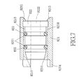
- the rotating unit 82 includes a rotating member 821, a sleeve 822, and at least one soft ring buffer 823.
- the rotating member 821 includes a through-hole 8211 therein.
- the rotating member 821 further includes a track 8212 in an outer periphery thereof and a guiding block 8213 in the track 8212.
- the fastener 816 is slideable along the track 8212 to control movement of the rotating member 821 upon movement of the shade 9, thereby controlling unfolding, coiling and positioning of the shade 9.
- a side of the rotating member 821 facing the left fixed board 42 includes a plurality of projections 8214.
- the other side of the rotating member 821 facing an interior of the sleeve 81 includes two pressing blocks 8215.
- the sleeve 822 includes at least one annular groove 8221 in an outer periphery thereof, with a gap 8210 defined between the outer periphery of the sleeve 822 and an inner periphery of the through-hole 8211 of the rotating member 821.
- the sleeve 822 includes two annular grooves 8221, and the sleeve 822 has an axial hole 8222.
- Each soft ring buffer 823 has an outer diameter larger than an inner diameter of the rotating member 821 such that the soft ring buffer 823 pressing against the inner periphery of the through-hole 8211.
- Each soft ring buffer 823 can be made of silicon rubber to increase the friction force and heat resisting effect of the rotating member 821, which can be used to replace the buffering effect of the buffering device in conventional coilable shades.
- the positioning rod 83 includes a circular stop 831 received in the receiving space 817 of the sleeve 81.
- a side of the circular stop 831 facing the square axle hole 422 includes an axle 832 having a shape corresponding to the square axle hole 422.
- the other side of the circular stop 831 facing the rotating member 821 includes a plurality of projections 833 for engaging with the projections 8214 for positioning purposes.
- a spindle 834 protrudes from the other side of the circular stop 831 and has a shape corresponding to the axial hole of the sleeve and the coupling hole of the connecting seat.
- the spindle 834 has a screw hole 835 in an end thereof.
- the connecting seat 84 includes a left stop 841.
- a left threaded portion 842 protrudes from a side of the left stop 841.
- the other end of the coiling spring 72 is securely mounted around the left threaded portion 842.
- the left threaded portion 842 includes a left axle hole 843.
- the other end of the shaft 73 extends through and engages in the left axle hole 843.
- a coupling section 844 protrudes from the other side of the left stop 841 and includes a coupling hole 845 aligned with the left axle hole 843.
- the spindle 834 extends through the axial hole 8222 of the sleeve 822 and is fixed in the coupling hole 845 of the connecting seat 84.
- a crew 846 extends through the left axle hole 843 and is threadedly engaged in the screw hole 835.
- a shade 9 includes an end coiled around the outer periphery of the drum 71.
- a pull rod 91 is fixed to the other end of the shade 9.
- the coiling spring 72 of the coiling device 7 coupled to the control device 8 is stretched outward and rotates freely around the shaft 73.
- the rotating force of the coiling spring 72 is smaller than the frictional force of the soft ring buffers 823 such that the shade 9 is unfolded smoothly. If it is desired to coil the shade 9 by rotation in the counterclockwise direction, the coiling spring 72 of the coiling device 7 is tensioned and drives the rotating unit 82 of the control device 9 to rotate jointly.
- the soft ring buffers 823 made of silicon rubber and mounted between the sleeve 822 and the rotating member 821, when the rotating unit 82 rotates in the counterclockwise direction, the soft ring buffers 823 drives the rotating member 821 to change the position of the track 8212 to achieve unfolding, coiling, and positioning of the shade 9.
- This also provides a buffering effect to rotation of the rotating member 821 and coiling of the shade 9, which can be used to replace the buffering effect provided by the hydraulic buffering device in conventional coilable shades.
- the overall outer diameter of the control device 8 of the coilable shade 12 according to the present invention can be as small as 1.5 cm after assembly, which is not only suitable for coilable shades on doors and windows but also suitable for small shades used on doors of automobiles, providing a wider application.
- the coilable shade 12 according to the present invention can easily be operated and can be retained in any desired position, providing improvements over the conventional coilable shades.
Landscapes
- Engineering & Computer Science (AREA)
- Structural Engineering (AREA)
- Architecture (AREA)
- Civil Engineering (AREA)
- Mechanical Engineering (AREA)
- Operating, Guiding And Securing Of Roll- Type Closing Members (AREA)
Applications Claiming Priority (1)
| Application Number | Priority Date | Filing Date | Title |
|---|---|---|---|
| TW102122546A TW201500634A (zh) | 2013-06-25 | 2013-06-25 | 捲簾 |
Publications (1)
| Publication Number | Publication Date |
|---|---|
| EP2839980A1 true EP2839980A1 (de) | 2015-02-25 |
Family
ID=49356225
Family Applications (1)
| Application Number | Title | Priority Date | Filing Date |
|---|---|---|---|
| EP13187983.5A Withdrawn EP2839980A1 (de) | 2013-06-25 | 2013-10-09 | Aufwickelbare Blende |
Country Status (3)
| Country | Link |
|---|---|
| US (1) | US9062494B2 (de) |
| EP (1) | EP2839980A1 (de) |
| TW (1) | TW201500634A (de) |
Cited By (2)
| Publication number | Priority date | Publication date | Assignee | Title |
|---|---|---|---|---|
| CN108583234A (zh) * | 2016-10-26 | 2018-09-28 | 厦门中锁锁业科技有限公司 | 汽车前挡风玻璃遮阳收卷帘 |
| PL443744A1 (pl) * | 2023-02-10 | 2024-08-12 | Hanarol Spółka Z Ograniczoną Odpowiedzialnością | Mechanizm samohamujący rolety |
Families Citing this family (43)
| Publication number | Priority date | Publication date | Assignee | Title |
|---|---|---|---|---|
| US20150284999A1 (en) * | 2014-04-02 | 2015-10-08 | Tai-Ping Liu | Apparatus for Damping a Reel |
| US9631425B2 (en) * | 2015-09-08 | 2017-04-25 | Crestron Electronics, Inc. | Roller shade with a pretensioned spring and method for pretensioning the spring |
| CN205605050U (zh) * | 2016-01-22 | 2016-09-28 | 亿丰综合工业股份有限公司 | 窗帘的阻尼装置 |
| CN205532187U (zh) * | 2016-01-29 | 2016-08-31 | 亿丰综合工业股份有限公司 | 窗帘升降控制结构 |
| KR101774567B1 (ko) * | 2016-11-21 | 2017-09-05 | (주)한국윈텍 | 코드리스 블라인드장치 |
| KR101717047B1 (ko) * | 2016-12-26 | 2017-03-27 | 곽재석 | 롤 블라인드의 스프링 장력 사전 구속장치 |
| US10047557B2 (en) * | 2017-01-18 | 2018-08-14 | Macauto Industrial Co., Ltd. | Side plate pressing device for a vehicle curtain |
| US10501988B2 (en) * | 2017-02-02 | 2019-12-10 | Hunter Douglas Inc. | Power assist module for coverings for architectural structures |
| US10378276B2 (en) * | 2017-03-02 | 2019-08-13 | Bandalux Industrial, S.A. | Fastening system for a decorative valance of a roller blind and a decorative valance of a curtain provided with a fastening system |
| US20180305980A1 (en) * | 2017-04-24 | 2018-10-25 | David R. Hall | Spring-Tensioned Roll-Up Wall |
| USD874183S1 (en) | 2017-05-19 | 2020-02-04 | Lutron Technology Company Llc | Bracket cover applied to a window treatment |
| USD943401S1 (en) | 2017-04-28 | 2022-02-15 | Lutron Technology Company Llc | Window treatment |
| US11957261B2 (en) | 2017-04-28 | 2024-04-16 | Lutron Technology Company Llc | Window treatment mounting bracket |
| USD871795S1 (en) | 2017-04-28 | 2020-01-07 | Lutron Technology Company Llc | Hem bar applied to a window treatment |
| USD871105S1 (en) | 2017-05-03 | 2019-12-31 | Lutron Technology Company Llc | Hem bar applied to a window treament |
| US10393206B2 (en) * | 2017-05-16 | 2019-08-27 | Chih-Yung Wang | Buffer device for small-sized roller shade |
| DE102017110746A1 (de) * | 2017-05-17 | 2018-11-22 | Roof Systems Germany Gmbh | Dachrollosystem für ein Kraftahrzeug und Verfahren zur Montage eines Dachrollosystems für ein Kraftfahrzeug |
| DE102017111734B4 (de) * | 2017-05-30 | 2022-09-08 | Webasto SE | Rolloanordnung mit Hüllrohranordnung umfassender Wickelwelle |
| USD883776S1 (en) | 2017-09-01 | 2020-05-12 | Lutron Technology Company Llc | Bracket applied to a window treatment |
| US10738530B2 (en) | 2018-01-16 | 2020-08-11 | Crestron Electronics, Inc. | Motor pretensioned roller shade |
| US11643864B2 (en) | 2018-01-23 | 2023-05-09 | Pella Corporation | Screen edge retention and screen rethreading features for a hidden screen assembly and a fenestration assembly |
| TWM567067U (zh) * | 2018-05-11 | 2018-09-21 | 慶豐富實業股份有限公司 | Pull curtain structure |
| US11008807B2 (en) * | 2018-10-18 | 2021-05-18 | Nien Made Enterprise Co., Ltd. | Position-fixing system |
| CN109989698A (zh) * | 2019-02-19 | 2019-07-09 | 广州市掬水帘饰品有限公司 | 一种无绳卷帘用弹簧结构 |
| CN109958387A (zh) * | 2019-05-05 | 2019-07-02 | 厦门泰阳和工贸有限公司 | 一种窗帘卷收装置 |
| US11399607B2 (en) * | 2019-08-06 | 2022-08-02 | Carrie K. Kelsch | Retractable necklace travel scroll |
| US11744339B2 (en) | 2019-08-06 | 2023-09-05 | Carrie K. Kelsch | Retractable jewelry travel scroll |
| CN110712499B (zh) * | 2019-09-25 | 2025-03-07 | 董克思 | 一种磁性减速结构及遮阳帘 |
| US20210115731A1 (en) * | 2019-10-18 | 2021-04-22 | Ply Gem Industries, Inc. | Apparatus and system for a concealed screen assembly |
| US12000208B2 (en) | 2020-01-31 | 2024-06-04 | Pella Corporation | Integrated pleated screen assembly |
| EP4176154A1 (de) * | 2020-07-02 | 2023-05-10 | Springs Window Fashions, LLC | Rolloanordnung |
| USD953148S1 (en) | 2020-08-14 | 2022-05-31 | Lutron Technology Company Llc | Bracket applied to a window treatment |
| USD953847S1 (en) | 2020-09-04 | 2022-06-07 | Lutron Technology Company Llc | Bracket applied to a window treatment |
| CN112512254B (zh) * | 2020-12-22 | 2022-07-29 | 东北农业大学 | 垂起无人机多功能集成地面控制装置 |
| CN215804287U (zh) * | 2021-02-04 | 2022-02-11 | 宁波振飞窗饰制品有限公司 | 一种弹簧棒驱动的手托斑马帘 |
| USD962044S1 (en) | 2021-02-26 | 2022-08-30 | Lutron Technology Company Llc | Bracket applied to a window treatment |
| USD962043S1 (en) | 2021-02-26 | 2022-08-30 | Lutron Technology Company Llc | Bracket applied to a window treatment |
| CN113266262A (zh) * | 2021-06-28 | 2021-08-17 | 无锡万斯家居科技股份有限公司 | 一种改进型无拉绳罗马帘卷帘 |
| USD1006611S1 (en) | 2022-02-28 | 2023-12-05 | Lutron Technology Company Llc | Bracket applied to a window treatment |
| USD1008785S1 (en) | 2022-02-28 | 2023-12-26 | Lutron Technology Company Llc | Bracket set applied to a window treatment |
| USD1046604S1 (en) | 2022-09-16 | 2024-10-15 | Lutron Technology Company Llc | Bracket for a window |
| USD1062441S1 (en) | 2022-09-16 | 2025-02-18 | Lutron Technology Company Llc | Set of brackets for window treatment |
| TWI884069B (zh) * | 2024-08-22 | 2025-05-11 | 安得富興業有限公司 | 捲簾輔助捲收裝置 |
Citations (2)
| Publication number | Priority date | Publication date | Assignee | Title |
|---|---|---|---|---|
| DE202005018484U1 (de) * | 2005-11-24 | 2006-03-16 | Wang, Chih-Yung, Linbian | Aufrolldämpfer für ein Rollo |
| US20120152470A1 (en) * | 2010-12-15 | 2012-06-21 | Chicology, Inc. | Decelerating device integrated with blind structure |
Family Cites Families (9)
| Publication number | Priority date | Publication date | Assignee | Title |
|---|---|---|---|---|
| US5566741A (en) * | 1993-06-02 | 1996-10-22 | Kabushiki Kaisha Nichibei | Roll screen apparatus |
| US7210513B2 (en) * | 2001-10-22 | 2007-05-01 | 420820 Ontario Limited | Screen frame with integral roll screen compartment and improvements thereof |
| ITBO20020082A1 (it) * | 2002-02-19 | 2003-08-19 | Dalex S R L | Gruppo operativo per tendine con rullo avvolgitore |
| TWM306842U (en) * | 2006-09-05 | 2007-03-01 | Shr-Yuan Chen | Improved axis of expanding and contracting device for window curtain |
| US8281846B2 (en) * | 2007-10-24 | 2012-10-09 | Xiangrong Zhu | Curtain |
| BR112012018127B1 (pt) * | 2010-01-22 | 2020-07-21 | Hunter Douglas, Inc. | disposição assistida por força para uma cobertura para uma abertura arquitetural e método para proporcionar assistência de força a uma persiana de rolo que tem um tubo giratório |
| US8746320B2 (en) * | 2010-02-26 | 2014-06-10 | Teh Yor Co., Ltd. | Window covering with improved controls |
| US8356653B2 (en) * | 2010-08-25 | 2013-01-22 | Teh Yor Co., Ltd. | Control module having a clutch for raising and lowering a window shade |
| TWI604124B (zh) * | 2012-02-23 | 2017-11-01 | 德侑股份有限公司 | 窗簾及其控制模組 |
-
2013
- 2013-06-25 TW TW102122546A patent/TW201500634A/zh unknown
- 2013-10-09 EP EP13187983.5A patent/EP2839980A1/de not_active Withdrawn
- 2013-10-18 US US14/057,299 patent/US9062494B2/en active Active
Patent Citations (2)
| Publication number | Priority date | Publication date | Assignee | Title |
|---|---|---|---|---|
| DE202005018484U1 (de) * | 2005-11-24 | 2006-03-16 | Wang, Chih-Yung, Linbian | Aufrolldämpfer für ein Rollo |
| US20120152470A1 (en) * | 2010-12-15 | 2012-06-21 | Chicology, Inc. | Decelerating device integrated with blind structure |
Cited By (3)
| Publication number | Priority date | Publication date | Assignee | Title |
|---|---|---|---|---|
| CN108583234A (zh) * | 2016-10-26 | 2018-09-28 | 厦门中锁锁业科技有限公司 | 汽车前挡风玻璃遮阳收卷帘 |
| PL443744A1 (pl) * | 2023-02-10 | 2024-08-12 | Hanarol Spółka Z Ograniczoną Odpowiedzialnością | Mechanizm samohamujący rolety |
| PL248978B1 (pl) * | 2023-02-10 | 2026-02-16 | Hanarol Spolka Z Ograniczona Odpowiedzialnoscia | Mechanizm samohamujący rolety |
Also Published As
| Publication number | Publication date |
|---|---|
| TWI513891B (de) | 2015-12-21 |
| TW201500634A (zh) | 2015-01-01 |
| US20140374036A1 (en) | 2014-12-25 |
| US9062494B2 (en) | 2015-06-23 |
Similar Documents
| Publication | Publication Date | Title |
|---|---|---|
| US9062494B2 (en) | Coilable shade | |
| US9816317B2 (en) | Spring-assisted cordless roller shade without clutch system | |
| US8556204B2 (en) | Curtain control device | |
| KR200472441Y1 (ko) | 롤러블라인드용 드럼 구동장치의 개량 구조체 | |
| US8931541B2 (en) | Motorized drive unit assembly for a shade system | |
| US20150300086A1 (en) | Spring-assisted cordless roller shade without clutch system | |
| US9963933B2 (en) | Blind body braking mechanism for non-cord window blind assembly | |
| CN101139910B (zh) | 一种卷帘用的卷筒驱动装置 | |
| US20160130863A1 (en) | Light Input-adjustable Window Shade | |
| US20160298385A1 (en) | Blind body brake mechanism for non pull cord window blind | |
| US8286685B2 (en) | Limit mechanism of upper stop level and lower stop level for rolling door | |
| KR101841357B1 (ko) | 방화문 자동폐쇄장치 | |
| TWI684422B (zh) | 捲軸式屏幕及其屏幕定位裝置 | |
| US20160090771A1 (en) | Cylinder Type Door Operator | |
| CN101476443A (zh) | 一种卷帘用的卷筒驱动装置 | |
| CN106089003B (zh) | 日照遮挡装置的速度调节装置 | |
| KR102353416B1 (ko) | 롤업스크린 및 그 스크린 포지셔닝 장치 | |
| CN201148833Y (zh) | 一种卷帘用的卷筒驱动装置 | |
| CN103764936B (zh) | 连接装置和卷帘 | |
| JP6677577B2 (ja) | 制動装置、自動移動装置および建具 | |
| JP2018009423A (ja) | 自動巻取式スクリーン装置の制動装置 | |
| CN104763306A (zh) | 卷帘 | |
| US20070125502A1 (en) | Window blind structure | |
| CN211692251U (zh) | 一种手推卷帘弹簧系统及其组成的手推卷帘 | |
| EP2899359B1 (de) | Vorrichtung zum Vorspannen einer Feder eines Rollvorhangs |
Legal Events
| Date | Code | Title | Description |
|---|---|---|---|
| PUAI | Public reference made under article 153(3) epc to a published international application that has entered the european phase |
Free format text: ORIGINAL CODE: 0009012 |
|
| 17P | Request for examination filed |
Effective date: 20140331 |
|
| AK | Designated contracting states |
Kind code of ref document: A1 Designated state(s): AL AT BE BG CH CY CZ DE DK EE ES FI FR GB GR HR HU IE IS IT LI LT LU LV MC MK MT NL NO PL PT RO RS SE SI SK SM TR |
|
| AX | Request for extension of the european patent |
Extension state: BA ME |
|
| STAA | Information on the status of an ep patent application or granted ep patent |
Free format text: STATUS: THE APPLICATION IS DEEMED TO BE WITHDRAWN |
|
| 18D | Application deemed to be withdrawn |
Effective date: 20150826 |