EP2840645A1 - Positive elektrode für luftbatterie und verfahren zur herstellung davon - Google Patents
Positive elektrode für luftbatterie und verfahren zur herstellung davon Download PDFInfo
- Publication number
- EP2840645A1 EP2840645A1 EP13778564.8A EP13778564A EP2840645A1 EP 2840645 A1 EP2840645 A1 EP 2840645A1 EP 13778564 A EP13778564 A EP 13778564A EP 2840645 A1 EP2840645 A1 EP 2840645A1
- Authority
- EP
- European Patent Office
- Prior art keywords
- fluid
- tight gas
- positive electrode
- layer
- permeable layer
- Prior art date
- Legal status (The legal status is an assumption and is not a legal conclusion. Google has not performed a legal analysis and makes no representation as to the accuracy of the status listed.)
- Granted
Links
Images
Classifications
-
- H—ELECTRICITY
- H01—ELECTRIC ELEMENTS
- H01M—PROCESSES OR MEANS, e.g. BATTERIES, FOR THE DIRECT CONVERSION OF CHEMICAL ENERGY INTO ELECTRICAL ENERGY
- H01M4/00—Electrodes
- H01M4/86—Inert electrodes with catalytic activity, e.g. for fuel cells
- H01M4/8605—Porous electrodes
- H01M4/8626—Porous electrodes characterised by the form
-
- H—ELECTRICITY
- H01—ELECTRIC ELEMENTS
- H01M—PROCESSES OR MEANS, e.g. BATTERIES, FOR THE DIRECT CONVERSION OF CHEMICAL ENERGY INTO ELECTRICAL ENERGY
- H01M4/00—Electrodes
- H01M4/86—Inert electrodes with catalytic activity, e.g. for fuel cells
- H01M4/8605—Porous electrodes
-
- B—PERFORMING OPERATIONS; TRANSPORTING
- B29—WORKING OF PLASTICS; WORKING OF SUBSTANCES IN A PLASTIC STATE IN GENERAL
- B29C—SHAPING OR JOINING OF PLASTICS; SHAPING OF MATERIAL IN A PLASTIC STATE, NOT OTHERWISE PROVIDED FOR; AFTER-TREATMENT OF THE SHAPED PRODUCTS, e.g. REPAIRING
- B29C41/00—Shaping by coating a mould, core or other substrate, i.e. by depositing material and stripping-off the shaped article; Apparatus therefor
- B29C41/003—Shaping by coating a mould, core or other substrate, i.e. by depositing material and stripping-off the shaped article; Apparatus therefor characterised by the choice of material
-
- B—PERFORMING OPERATIONS; TRANSPORTING
- B29—WORKING OF PLASTICS; WORKING OF SUBSTANCES IN A PLASTIC STATE IN GENERAL
- B29C—SHAPING OR JOINING OF PLASTICS; SHAPING OF MATERIAL IN A PLASTIC STATE, NOT OTHERWISE PROVIDED FOR; AFTER-TREATMENT OF THE SHAPED PRODUCTS, e.g. REPAIRING
- B29C41/00—Shaping by coating a mould, core or other substrate, i.e. by depositing material and stripping-off the shaped article; Apparatus therefor
- B29C41/02—Shaping by coating a mould, core or other substrate, i.e. by depositing material and stripping-off the shaped article; Apparatus therefor for making articles of definite length, i.e. discrete articles
- B29C41/22—Making multilayered or multicoloured articles
-
- B—PERFORMING OPERATIONS; TRANSPORTING
- B29—WORKING OF PLASTICS; WORKING OF SUBSTANCES IN A PLASTIC STATE IN GENERAL
- B29C—SHAPING OR JOINING OF PLASTICS; SHAPING OF MATERIAL IN A PLASTIC STATE, NOT OTHERWISE PROVIDED FOR; AFTER-TREATMENT OF THE SHAPED PRODUCTS, e.g. REPAIRING
- B29C41/00—Shaping by coating a mould, core or other substrate, i.e. by depositing material and stripping-off the shaped article; Apparatus therefor
- B29C41/34—Component parts, details or accessories; Auxiliary operations
- B29C41/36—Feeding the material on to the mould, core or other substrate
-
- B—PERFORMING OPERATIONS; TRANSPORTING
- B29—WORKING OF PLASTICS; WORKING OF SUBSTANCES IN A PLASTIC STATE IN GENERAL
- B29C—SHAPING OR JOINING OF PLASTICS; SHAPING OF MATERIAL IN A PLASTIC STATE, NOT OTHERWISE PROVIDED FOR; AFTER-TREATMENT OF THE SHAPED PRODUCTS, e.g. REPAIRING
- B29C41/00—Shaping by coating a mould, core or other substrate, i.e. by depositing material and stripping-off the shaped article; Apparatus therefor
- B29C41/34—Component parts, details or accessories; Auxiliary operations
- B29C41/42—Removing articles from moulds, cores or other substrates
-
- B—PERFORMING OPERATIONS; TRANSPORTING
- B29—WORKING OF PLASTICS; WORKING OF SUBSTANCES IN A PLASTIC STATE IN GENERAL
- B29C—SHAPING OR JOINING OF PLASTICS; SHAPING OF MATERIAL IN A PLASTIC STATE, NOT OTHERWISE PROVIDED FOR; AFTER-TREATMENT OF THE SHAPED PRODUCTS, e.g. REPAIRING
- B29C41/00—Shaping by coating a mould, core or other substrate, i.e. by depositing material and stripping-off the shaped article; Apparatus therefor
- B29C41/34—Component parts, details or accessories; Auxiliary operations
- B29C41/46—Heating or cooling
-
- H—ELECTRICITY
- H01—ELECTRIC ELEMENTS
- H01M—PROCESSES OR MEANS, e.g. BATTERIES, FOR THE DIRECT CONVERSION OF CHEMICAL ENERGY INTO ELECTRICAL ENERGY
- H01M12/00—Hybrid cells; Manufacture thereof
- H01M12/04—Hybrid cells; Manufacture thereof composed of a half-cell of the fuel-cell type and of a half-cell of the primary-cell type
- H01M12/06—Hybrid cells; Manufacture thereof composed of a half-cell of the fuel-cell type and of a half-cell of the primary-cell type with one metallic and one gaseous electrode
-
- H—ELECTRICITY
- H01—ELECTRIC ELEMENTS
- H01M—PROCESSES OR MEANS, e.g. BATTERIES, FOR THE DIRECT CONVERSION OF CHEMICAL ENERGY INTO ELECTRICAL ENERGY
- H01M12/00—Hybrid cells; Manufacture thereof
- H01M12/08—Hybrid cells; Manufacture thereof composed of a half-cell of a fuel-cell type and a half-cell of the secondary-cell type
-
- H—ELECTRICITY
- H01—ELECTRIC ELEMENTS
- H01M—PROCESSES OR MEANS, e.g. BATTERIES, FOR THE DIRECT CONVERSION OF CHEMICAL ENERGY INTO ELECTRICAL ENERGY
- H01M4/00—Electrodes
- H01M4/86—Inert electrodes with catalytic activity, e.g. for fuel cells
- H01M4/8636—Inert electrodes with catalytic activity, e.g. for fuel cells with a gradient in another property than porosity
- H01M4/8642—Gradient in composition
-
- H—ELECTRICITY
- H01—ELECTRIC ELEMENTS
- H01M—PROCESSES OR MEANS, e.g. BATTERIES, FOR THE DIRECT CONVERSION OF CHEMICAL ENERGY INTO ELECTRICAL ENERGY
- H01M4/00—Electrodes
- H01M4/86—Inert electrodes with catalytic activity, e.g. for fuel cells
- H01M4/8647—Inert electrodes with catalytic activity, e.g. for fuel cells consisting of more than one material, e.g. consisting of composites
- H01M4/8657—Inert electrodes with catalytic activity, e.g. for fuel cells consisting of more than one material, e.g. consisting of composites layered
-
- H—ELECTRICITY
- H01—ELECTRIC ELEMENTS
- H01M—PROCESSES OR MEANS, e.g. BATTERIES, FOR THE DIRECT CONVERSION OF CHEMICAL ENERGY INTO ELECTRICAL ENERGY
- H01M4/00—Electrodes
- H01M4/86—Inert electrodes with catalytic activity, e.g. for fuel cells
- H01M4/8663—Selection of inactive substances as ingredients for catalytic active masses, e.g. binders, fillers
- H01M4/8673—Electrically conductive fillers
-
- H—ELECTRICITY
- H01—ELECTRIC ELEMENTS
- H01M—PROCESSES OR MEANS, e.g. BATTERIES, FOR THE DIRECT CONVERSION OF CHEMICAL ENERGY INTO ELECTRICAL ENERGY
- H01M4/00—Electrodes
- H01M4/86—Inert electrodes with catalytic activity, e.g. for fuel cells
- H01M4/88—Processes of manufacture
- H01M4/8803—Supports for the deposition of the catalytic active composition
- H01M4/8807—Gas diffusion layers
-
- H—ELECTRICITY
- H01—ELECTRIC ELEMENTS
- H01M—PROCESSES OR MEANS, e.g. BATTERIES, FOR THE DIRECT CONVERSION OF CHEMICAL ENERGY INTO ELECTRICAL ENERGY
- H01M4/00—Electrodes
- H01M4/86—Inert electrodes with catalytic activity, e.g. for fuel cells
- H01M4/88—Processes of manufacture
- H01M4/8803—Supports for the deposition of the catalytic active composition
- H01M4/8814—Temporary supports, e.g. decal
-
- H—ELECTRICITY
- H01—ELECTRIC ELEMENTS
- H01M—PROCESSES OR MEANS, e.g. BATTERIES, FOR THE DIRECT CONVERSION OF CHEMICAL ENERGY INTO ELECTRICAL ENERGY
- H01M4/00—Electrodes
- H01M4/86—Inert electrodes with catalytic activity, e.g. for fuel cells
- H01M4/88—Processes of manufacture
- H01M4/8825—Methods for deposition of the catalytic active composition
- H01M4/8828—Coating with slurry or ink
-
- H—ELECTRICITY
- H01—ELECTRIC ELEMENTS
- H01M—PROCESSES OR MEANS, e.g. BATTERIES, FOR THE DIRECT CONVERSION OF CHEMICAL ENERGY INTO ELECTRICAL ENERGY
- H01M4/00—Electrodes
- H01M4/86—Inert electrodes with catalytic activity, e.g. for fuel cells
- H01M4/88—Processes of manufacture
- H01M4/8878—Treatment steps after deposition of the catalytic active composition or after shaping of the electrode being free-standing body
- H01M4/8882—Heat treatment, e.g. drying, baking
-
- B—PERFORMING OPERATIONS; TRANSPORTING
- B29—WORKING OF PLASTICS; WORKING OF SUBSTANCES IN A PLASTIC STATE IN GENERAL
- B29K—INDEXING SCHEME ASSOCIATED WITH SUBCLASSES B29B, B29C OR B29D, RELATING TO MOULDING MATERIALS OR TO MATERIALS FOR MOULDS, REINFORCEMENTS, FILLERS OR PREFORMED PARTS, e.g. INSERTS
- B29K2027/00—Use of polyvinylhalogenides or derivatives thereof as moulding material
- B29K2027/12—Use of polyvinylhalogenides or derivatives thereof as moulding material containing fluorine
- B29K2027/18—PTFE, i.e. polytetrafluoroethylene, e.g. ePTFE, i.e. expanded polytetrafluoroethylene
-
- B—PERFORMING OPERATIONS; TRANSPORTING
- B29—WORKING OF PLASTICS; WORKING OF SUBSTANCES IN A PLASTIC STATE IN GENERAL
- B29K—INDEXING SCHEME ASSOCIATED WITH SUBCLASSES B29B, B29C OR B29D, RELATING TO MOULDING MATERIALS OR TO MATERIALS FOR MOULDS, REINFORCEMENTS, FILLERS OR PREFORMED PARTS, e.g. INSERTS
- B29K2105/00—Condition, form or state of moulded material or of the material to be shaped
- B29K2105/0005—Condition, form or state of moulded material or of the material to be shaped containing compounding ingredients
- B29K2105/002—Agents changing electric characteristics
- B29K2105/0023—Agents changing electric characteristics improving electric conduction
-
- B—PERFORMING OPERATIONS; TRANSPORTING
- B29—WORKING OF PLASTICS; WORKING OF SUBSTANCES IN A PLASTIC STATE IN GENERAL
- B29K—INDEXING SCHEME ASSOCIATED WITH SUBCLASSES B29B, B29C OR B29D, RELATING TO MOULDING MATERIALS OR TO MATERIALS FOR MOULDS, REINFORCEMENTS, FILLERS OR PREFORMED PARTS, e.g. INSERTS
- B29K2105/00—Condition, form or state of moulded material or of the material to be shaped
- B29K2105/04—Condition, form or state of moulded material or of the material to be shaped cellular or porous
-
- B—PERFORMING OPERATIONS; TRANSPORTING
- B29—WORKING OF PLASTICS; WORKING OF SUBSTANCES IN A PLASTIC STATE IN GENERAL
- B29K—INDEXING SCHEME ASSOCIATED WITH SUBCLASSES B29B, B29C OR B29D, RELATING TO MOULDING MATERIALS OR TO MATERIALS FOR MOULDS, REINFORCEMENTS, FILLERS OR PREFORMED PARTS, e.g. INSERTS
- B29K2995/00—Properties of moulding materials, reinforcements, fillers, preformed parts or moulds
- B29K2995/0037—Other properties
- B29K2995/0065—Permeability to gases
-
- B—PERFORMING OPERATIONS; TRANSPORTING
- B29—WORKING OF PLASTICS; WORKING OF SUBSTANCES IN A PLASTIC STATE IN GENERAL
- B29L—INDEXING SCHEME ASSOCIATED WITH SUBCLASS B29C, RELATING TO PARTICULAR ARTICLES
- B29L2031/00—Other particular articles
- B29L2031/34—Electrical apparatus, e.g. sparking plugs or parts thereof
- B29L2031/3468—Batteries, accumulators or fuel cells
-
- H—ELECTRICITY
- H01—ELECTRIC ELEMENTS
- H01M—PROCESSES OR MEANS, e.g. BATTERIES, FOR THE DIRECT CONVERSION OF CHEMICAL ENERGY INTO ELECTRICAL ENERGY
- H01M4/00—Electrodes
- H01M4/86—Inert electrodes with catalytic activity, e.g. for fuel cells
- H01M2004/8678—Inert electrodes with catalytic activity, e.g. for fuel cells characterised by the polarity
- H01M2004/8689—Positive electrodes
-
- H—ELECTRICITY
- H01—ELECTRIC ELEMENTS
- H01M—PROCESSES OR MEANS, e.g. BATTERIES, FOR THE DIRECT CONVERSION OF CHEMICAL ENERGY INTO ELECTRICAL ENERGY
- H01M4/00—Electrodes
- H01M4/86—Inert electrodes with catalytic activity, e.g. for fuel cells
- H01M4/8663—Selection of inactive substances as ingredients for catalytic active masses, e.g. binders, fillers
- H01M4/8668—Binders
-
- Y—GENERAL TAGGING OF NEW TECHNOLOGICAL DEVELOPMENTS; GENERAL TAGGING OF CROSS-SECTIONAL TECHNOLOGIES SPANNING OVER SEVERAL SECTIONS OF THE IPC; TECHNICAL SUBJECTS COVERED BY FORMER USPC CROSS-REFERENCE ART COLLECTIONS [XRACs] AND DIGESTS
- Y02—TECHNOLOGIES OR APPLICATIONS FOR MITIGATION OR ADAPTATION AGAINST CLIMATE CHANGE
- Y02E—REDUCTION OF GREENHOUSE GAS [GHG] EMISSIONS, RELATED TO ENERGY GENERATION, TRANSMISSION OR DISTRIBUTION
- Y02E60/00—Enabling technologies; Technologies with a potential or indirect contribution to GHG emissions mitigation
- Y02E60/10—Energy storage using batteries
Definitions
- the present invention relates to a positive electrode used in air cells. Specifically, the present invention relates to a positive electrode for air cells which can prevent leakage of electrolysis solution and implement excellent handleability and easy series connection of the air cells.
- Air cells are power supplies which are economical because the cells use oxygen in the air as an active material and can be used for a long period of time without maintenance.
- button-type air cells are known.
- a button-type air cell uses a casing assembly in which a metallic negative electrode casing and a metallic positive electrode casing having air holes are fitted to each other with a gasket interposed therebetween.
- a negative electrode, an electrolysis solution, a separator, an air electrode (a positive electrode), a water-repellent film, and the like are arranged.
- the internal space of the casing assembly is divided by the separator.
- One of the divided spaces is filled with zinc and electrolysis solution, in which zinc is immersed, to serve as the negative electrode, and the other space includes a catalyst to serve as the air electrode (the positive electrode).
- the water-repellent film is composed of porous membrane made of polytetrafluoroethylene (PTFE) and is provided on the surface of the air electrode opposite to the separator. Diffusion paper is tightly attached to the water-repellent film.
- oxygen in the air as a positive electrode active material is introduced through the air holes provided in the bottom of the positive electrode casing and is supplied to the air electrode through the diffusion paper and water-repellent film.
- the diffusion paper serves a function of uniformly supplying oxygen to the entire surface of the air electrode.
- the water-repellent film serves a function of supplying oxygen to the inside of the cell (the positive electrode) and a function of preventing the electrolysis solution from leaking out of the cell through the air holes.
- Patent Literature 1 Japanese Patent Unexamined Publication No. 11-54130
- the leakage of electrolysis solution due to chunks of catalyst can be prevented, but the leakage of electrolysis solution through the air holes is still prevented by water-repellent film made of PTFE separately provided from the air electrode (the positive electrode) as used to be. Moreover, the water-repellent film could reduce the electrical conductivity, and it is therefore necessary to provide the current collector in the catalyst layer.
- An object of the present invention is to provide a positive electrode for air cells which can prevent leakage of electrolysis solution and is useful for series connection of the air cells while enhancing the manufacturing efficiency and handleability of the air cells, and to provide a method of manufacturing the positive electrode for air cells.
- a positive electrode for an air cell includes: a catalyst layer composed of a porous layer containing electrical conductive carbon, a binder, and a catalyst component; and a fluid-tight gas-permeable layer composed of a porous layer containing electrical conductive carbon and a binder, in which the fluid-tight gas-permeable layer is stacked on the catalyst layer.
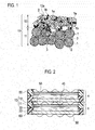
- Fig. 1 schematically illustrates a microstructure of the positive electrode for air cells according to the embodiment.
- a positive electrode layer 10 as the positive electrode for air cells of the embodiment includes a catalyst layer 11 and a fluid-tight gas-permeable layer 12, and the fluid-tight gas-permeable layer 12 is stacked on the catalyst layer 11.
- This specification describes that the fluid-tight gas-permeable layer 12 is staked on the catalyst layer 11 for convenience of explanation.
- the fluid-tight gas-permeable layer 12 only needs to be adjacent to the catalyst layer 11 and to be provided on the side where air intake holes or an air channel to the catalyst layer 11 are provided, that is, the side opposite to the side where the electrolysis solution is provided. Accordingly, the embodiment is unnecessarily limited by the term "stacked".
- the catalyst layer 11 contains carbon particles 1 as framework carbon, carbon black 1b as an example of an electrical conductive path material, catalyst particles 3 as a catalyst component, and a binder 2.
- the carbon particles 1, carbon black 1b, and catalyst particles 3 are bound by the binder 2 to form a porous layer.
- the fluid-tight gas-permeable layer 12 contains graphite 1a as an example of the framework carbon, carbon black 1b as an example of the electrical conductive path material, and the binder 2.
- the graphite 1a and carbon black 1b are bound by the binder 2 to form a porous layer.
- the catalyst layer 11 and fluid-tight gas-permeable layer 12 are bound by the binder 2 to be substantially integrated.
- the integration can be conducted by integral formation of a later-described method of manufacturing the positive electrode for air cells.
- the carbon particles 1, graphite (framework carbon) 1a, and carbon black (electrical conductive path material) 1b are individually composed of electrical conductive carbon.
- filamentous carbon (not shown) composed of electrical conductive carbon can be added to at least one of the catalyst layer 11 and fluid-tight gas-permeable layer 12.
- the addition of filamentous carbon can increase the mechanical strength, especially, tensile strength of the obtained positive electrode.
- filamentous carbon is added to the fluid-tight gas-permeable layer in particular. Because of the increase in mechanical strength, the fluid-tight gas-permeable layer can be made thinner. This can increase the output of the positive electrode while reducing the electric resistance.
- the catalyst layer 11 and fluid-tight gas-permeable layer 12 are porous layers as described above.
- the fluid-tight gas-permeable layer 12 has a pore diameter and a porosity that allow oxygen in the air to be transmitted therethrough but does not allow electrolysis solution (not shown) to be transmitted.
- the pore diameter of the fluid-tight gas-permeable layer 12 is preferably about 0.1 ⁇ m to 20 ⁇ m, and the porosity thereof is preferably about 10 to 80%.
- the pore diameter and porosity can be measured by a pore distribution measurement apparatus such as a porosimeter.
- the fluid-tight gas-permeable layer 12 has a high liquid repellency (water repellency) to the electrolysis solution of the air cell, and the repellency of the fluid-tight gas-permeable layer 12 is not lower than that of the catalyst layer 11, that is, equal to or higher than that of the catalyst layer 11. This can sufficiently prevent the electrolysis solution from leaking out of the air cell through the not-shown air intake holes (air holes), air intake channel (air channels), or the like.
- the fluid-tight gas-permeable layer 12 has electrical conductivity by the contained graphite 1a as the framework carbon and the contained carbon black 1b as the electrical conductive path material.
- the fluid-tight gas-permeable layer 12 of the embodiment is extremely advantageous to constitute a series connection-type air cell outputting a large electromotive force as described later.
- Fig. 2 illustrates an example of battery packs including series connection-type air cells each having the positive electrode for air cells of the embodiment.
- the positive electrode layer 10 which includes the fluid-tight gas-permeable layer 12 stacked on the catalyst layer 11, and a negative electrode layer 20 are adjacent to each other with a separator 30 interposed therebetween, the separator 30 being impregnated with the electrolysis solution.
- the fluid-tight gas-permeable layer 12 of the positive electrode layer 10 is exposed to an air channel 40, so that oxygen in the air is supplied to the catalyst layer 11.
- a holder 60 is provided in the outer peripheries of the positive and negative electrode layers 10 and 20.
- the outer peripheries of the positive and negative electrode layers 10 and 20 are integrally joined to the holder 60. This prevents leakage of the electrolysis solution through the joint portion between the holder 60 and the positive and negative electrode layers 10 and 20.
- the air channel 40 between the air cells A and B is provided with a current collector 50 having a waveform cross-section.
- the stack structure in which the air cells A and B are stacked with the current collector 50 interposed therebetween is employed as described above to form the battery pack.
- the fluid-tight gas-permeable layer 12 has electrical conductivity as described above. Accordingly, the negative and positive electrode layers 20 and 10 opposed to each other can be electrically connected only by providing the current collector 50 in the air channel 40 as illustrated in the drawing. Accordingly, the battery pack including the air cells A and B connected in series can be easily obtained. In this case, the negative and positive electrode layers 20 and 10 are in contact with large area of the current collector 50 and can be electrically connected to the current collector 50 almost like via planar connection, thus reducing the electrical conducting loss.
- the positive electrode for air cells of this embodiment is suitable for a series connection-type battery pack having a structure as illustrated in Fig. 2 .
- the series connection-type battery pack having such a structure can easily implement large electromotive force and can be made compact as well as increasing the efficiency of assembly.
- the separator 30 is impregnated with the electrolysis solution (not shown).
- the electrolysis solution only needs to be in contact with the positive and negative electrodes and may be configured to fill the space between the positive and negative electrodes without using the separator 30.
- the electrolysis solution may be contained in the positive or negative electrodes or may be contained and held in the catalyst layer 11 and negative electrode layer 20.
- the fluid-tight gas-permeable layer 12 is also composed of a porous layer and therefore has a good contact with the catalyst layer 11 at the interface between the catalyst layer 11 and fluid-tight gas-permeable layer 12. It is therefore more likely to form a three-phase interface of the catalyst particles 3, oxygen, and electrolysis solution, thus implementing efficient power generation.
- the catalyst particles 3 as the catalyst component only need to be contained in the catalyst layer 11 but may be contained in the fluid-tight gas-permeable layer 12. However, from the perspective of preventing leakage of the electrolysis solution through the catalyst particles to the air channel and ensuring the electrical conduction of the current collector, it is preferable that the catalyst particles 3 as the catalyst component are contained in the catalyst layer 11 more than in the fluid-tight gas-permeable layer 12.
- the catalyst layer 11 contains preferably 50 % by mass or more of the total catalyst amount of the positive electrode for air cells and contains more preferably 70 % by mass or more of the total catalyst amount.
- the catalyst particles 3 are preferably contained in the fluid-tight gas-permeable layer 12 at a depth of 10 ⁇ m or more from a topmost surface 12a thereof.
- the effects of the present invention can be exerted even when the catalyst particles 3 are contained in a shallower area, that is, in a range of depth less than 10 nm from the top surface 12a of the fluid-tight gas-permeable layer 12.
- a small amount of electrolysis solution can leak to the air channel through the catalyst particles.
- the fluid-tight gas-permeable layer 12 has a liquid repellency higher than the catalyst layer 11. Moreover, it is preferable that the softening temperature of the fluid-tight gas-permeable layer is higher than that of the catalyst layer.
- the reason thereof which relates to the manufacturing method of the positive electrode for air cells, is because in the process of applying catalyst layer ink to the fluid-tight gas-permeable layer having high strength or attaching and fixing a separately produced catalyst layer to the same, the catalyst layer can be more easily joined to the fluid-tight gas-permeable layer if the catalyst layer is softened.
- the catalyst layer 11 is more easily stacked on the fluid-tight gas-permeable layer 12 by lowering the softening temperature of the catalyst layer to make the catalyst layer flexible.
- the softening temperatures of the fluid-tight gas-permeable layer and catalyst layer can be obtained by measurement of each layer in accordance with JIS K7191-2 (Plastics - Determination of temperature of deflection under load - Part 2: Plastics and ebonite).
- the above-described relation in softening temperature between the catalyst layer and fluid-tight gas-permeable layer can be adjusted mainly in accordance with the types and amounts of binders used in the both layers.
- the binders used in the both layers are composed of the same material or the same type of materials, the amount of binder in the fluid-tight gas-permeable layer needs to be set higher than the amount of binder in the catalyst layer.
- the ratio between the contents of the binders is set to a mass ratio of 7/10 to 1/10 (the binder content of the catalyst layer/the binder content of the fluid-tight gas-permeable layer), for example. Employment of the aforementioned ratio between the binder contents facilitates adjustment of the relation in liquid repellency between the fluid-tight gas-permeable layer and catalyst layer because of the liquid-repellent binders.
- the binders used in the both layers can be composed of different types of materials.
- the softening temperature (Vicat softening temperature, for example) of the binder of the fluid-tight gas-permeable layer is higher than the softening temperature of the binder of the catalyst layer.
- the difference in softening temperature between the binders used in the both layers can be properly changed in accordance with the intended use of the air cell, the type of electrolysis solution, the type of electrical conductive carbon, and the like.
- the difference in softening temperature between the binders of the fluid-tight gas-permeable layer and catalyst layer is set to about 30 to 250°C, for example.
- the Vicat softening temperature of the binders can be obtained in accordance with JIS K7206 (Plastics - Thermoplastic materials - Determination of Vicat softening temperature (VST)). Moreover, even when the binders of the both layers are of different types from each other, the contents thereof can be properly adjusted.
- the catalyst layer 11 and fluid-tight gas-permeable layer 12 can be integrally formed by the later-described manufacturing method, so that the both layers can be integrated.
- the integral formation significantly increases the manufacturing efficiency of the positive electrode.
- the improvement in the characteristics of the interface between the catalyst layer and fluid-tight gas-permeable layer reduces the IR resistance of the positive electrode.
- the electrical conductive carbon constituting each of the catalyst layer and fluid-tight gas-permeable layer only needs to be a carbon material having electrical conductivity and is not particularly limited.
- the electrical conductive carbon can be at least one selected from the group consisting of activated carbon, graphite, flake graphite, carbon black, and acetylene black other than diamond.
- the electrical conductive carbon is roughly classified by the functions thereof into framework carbons forming the main framework of the layer structure (the porous layer structure) and electrical conductive path materials useful to form electrical conductive paths in the layer.
- the aforementioned filamentous carbon can be also added to at least one of the catalyst layer and fluid-tight gas-permeable layer as the electrical conductive carbon.
- the filamentous carbon contributes to an increase in mechanical strength, reduction in layer thickness, and reduction in electrical resistance of the catalyst layer and fluid-tight gas-permeable layer.
- the filamentous carbon can be at least any one selected from the group consisting of carbon nanotubes (CNT), carbon nanofibers (CNF), and vapor grown carbon fibers (VGCF).
- the framework carbon can be at least one selected from the group consisting of activated carbon, graphite, and flake graphite. These materials have a nature to retain the form of independent particles in a porous layer to a certain degree. By using graphite or flake graphite, many gaps are comparatively more likely to be formed in the porous layer. Accordingly, graphite and flake graphite are particularly suitable for use as the framework carbon of the fluid-tight gas-permeable layer.
- the electrical conductive path material tends to aggregate into a chain (string) structure, and the coupled chains tend to function as electrical conductive paths.
- the electrical conductive path materials are used together with the framework carbon, in particular, the coupled chains of the electrical conductive path material are easily located in a weaving manner among the gaps formed by the framework carbon in the porous layer. This is extremely useful to enhance the electrical conduction of the porous layer as a whole.
- the framework carbon such as graphite or flake graphite tends to be provided so that planar portions and cleavage plane portions are aligned to extend in the direction of the application surface.
- the provision of the electrical conductive path material between the surfaces of the framework carbon can implement good electrical conduction in the thickness direction of the porous layer.
- the electrical conductive path material can be at least any one of carbon black and acetylene black.
- Acetylene black obtained by pyrolysis of acetylene gas tends to form the aforementioned chain structure, and the surface thereof exerts water repellency. Accordingly, acetylene black is particularly suitable for the electrical conductive path material of the fluid-tight gas-permeable layer.
- the particle diameters of the aforementioned framework carbon and electrical conductive path material depend on the air cell, intended electromotive force, and the like. However, typically, the average particle diameter of the framework carbon is preferably within a range between 5 ⁇ m and 300 ⁇ m, and the average particle diameter of the electrical conductive path material is preferably within a range between 50 nm and 500 nm. Setting the average particle diameter of the framework carbon in the aforementioned range can increase the electrical conduction in the in-plane direction of the framework carbon and the strength of the positive electrode. Moreover, setting the average particle diameter of the electrical conductive path material in the aforementioned range can increase the electrical conduction in the thickness direction of the porous layer and gas permeability of the fluid-tight gas-permeable layer. The average particle diameter (median diameter, D50) of the framework carbon and electrical conductive path material can be obtained by the dynamic light scattering method.
- the binders only need to have a function of binding the electrical conductive carbon such as the aforementioned framework carbon and electrical conductive path material to form a porous layer and preferably has repellency to the electrolysis solution, typically, water repellency.
- the binders can be: a thermoplastic polymer such as polyethylene (PE), polypropylene (PP), polyethylene terephthalate (PET), polyethernitrile (PEN), polyacrylonitrile (PAN), polyimide (PI), polyamide (PA), cellulose, carboxymethylcellulose (CMC), ethylene-vinyl acetate copolymer, polyvinylchloride (PVC), styrene-butadiene rubber (SBR), isoprene rubber, butadiene rubber, ethylene-propylene rubber, ethylene-propylene-diene copolymer, styrene-butadiene-styrene block copolymer and hydrogenated products thereof, styrene-isoprene-styrene block copolymer and hydrogenated products thereof; fluorine resin such as polyvinylidene fluoride (PVDF), polytetrafluoroethylene (PTFE), tetrafluoroethylene-hexa
- polyvinylidene fluoride, polyimide, styrene-butadiene rubber, carboxymethylcellulose, polypropylene, polytetrafluoroethylene, polyacrylonitrile, and polyamide are preferred.
- the binders may include either one of the above substances or two or more thereof.
- PTFE polytetrafluoroethylene
- PP polypropylene
- PFA tetrafluoroethylene-perfluoroalkylvinylether copolymer
- FEP tetrafluoroethylene-hexafluoropropylene copolymer
- ETFE ethylene-tetrafluoroethylene copolymer
- the catalyst component can be a conventionally-known electrode catalyst for air cell positive electrodes. Specific examples thereof include: metals such as platinum (Pt), ruthenium (Ru), iridium (Ir), rhodium (Rh), palladium (Pd), osmium (Os), tungsten (W), lead (Pb), iron (Fe), chromium (Cr), cobalt (Co), nickel (Ni), manganese (Mn), vanadium (V), molybdenum (Mo), gallium (Ga), and aluminum (Al); compounds thereof; and alloys thereof.
- the catalyst component can include either one of the above substances alone or two or more thereof.
- the shape and size of the catalyst component are not particularly limited and can be the same shape and size as the conventionally known catalyst components. However, it is preferable that the catalyst component is granular. Moreover, the average particle diameter of the catalyst particles as the catalyst component is preferably within a range between 30 nm and 100 ⁇ m. When the average particle diameter of the catalyst particles is in the aforementioned range, the balance between the catalyst utilization, that is associated with an effective electrode surface in which the electrochemical reaction proceeds, and the easy support of the catalyst can be controlled appropriately. The average particle diameter of the catalyst particles can be measured as a crystallite diameter obtained from the full width at half maximum of the diffraction peak of the catalyst component by X-ray diffraction.
- the content ratio between the electrical conductive carbon, binder, and catalyst components in the catalyst layer can be properly changed in accordance with the electromotive force and usage of the intended air cell and the like.
- the contents of the electrical conductive carbon, binder, and catalyst components are set to 30 to 85 % by mass, 5 to 30 % by mass, and 3 to 50 % by mass, respectively.
- the obtained air cell can provide enough output.
- the content ratio between the electrical conductive carbon and binder in the fluid-tight gas-permeable layer can be properly changed in accordance with the electromotive force and usage of the intended air cell or the like.
- the contents of the electrical conductive carbon and binder are set to 40 to 80 % by mass and 20 to 60 % by mass, respectively.
- the fluid-tight gas-permeable layer has enough electrical conduction
- the positive electrode has enough strength.
- the fluid-tight gas-permeable layer may contain the catalyst components, which is as described above.
- the electrical conductive carbon it is possible to use the framework carbon and electrical conductive path material together as described above.
- the mass ratio of the framework carbon to the electrical conductive path material in the catalyst layer is preferably set to 1/4 to 3/2 (framework carbon/electrical conductive path material).
- the mass ratio of the framework carbon to the electrical conductive path material in the fluid-tight gas-permeable layer is preferably set to 1/4 to 4/1 (framework carbon/electrical conductive path material).
- the mass ratio is in the aforementioned range, the obtained air cell can have enough strength and provide enough output.
- the negative electrode layer includes a negative-electrode active material composed of a metal or an alloy having a standard electrode potential lower than that of hydrogen, for example.
- the negative electrode layer can be made of a porous material in some situations.
- the metal having a standard electrode potential lower than that of hydrogen include lithium (Li), zinc (Zn), iron (Fe), aluminum (Al), magnesium (Mg), manganese (Mn), silicon (Si), titanium (Ti), chromium (Cr), and vanadium (V).
- alloys using some of the above metal elements are applicable.
- the negative-electrode active material can include either one of the aforementioned metals alone or two or more thereof.
- the alloys collectively refer to substances which are obtained by adding at least one metal element or non-metal element to a metal element and have metal properties.
- the alloys can be substances obtained by adding one or more metal elements or non-metal elements to the aforementioned metal elements. Alloys are classified by the composition into: eutectic alloy as a sort of mixture in which the constituent elements are separately crystallized; solid solution in which constituent elements are completely solved to each other; and an intermetallic compound or a metal-nonmetal compound of constituent elements.
- the alloy can employ any one of the aforementioned composition types.
- the alloy is not limited to the aforementioned substances and can be made of conventionally known materials applicable to air cells.
- the separator can be composed of a conventionally known material used in air cells.
- the separator in the light of the electrolysis solution which is a solution, can be preferably composed of glass paper not treated for water repellency, microporous film composed of polyolefin such as polyethylene or polypropylene.
- the electrolysis solution can be also conventionally known one.
- Examples of the electrolysis solution are water solutions or non-water solutions of potassium chloride, sodium chloride, and potassium hydroxide.
- the current collector only needs to have an electric current collecting function and is not particularly limited.
- the current collector can be made of metal such as stainless steel (SUS), copper, and nickel, for example.
- the current collector can be also composed of resin coated with an electric conductive material.
- the shape of the current collector is also not particularly limited and can be selected from various types of shapes including wire mesh shape, expanded metal shape, and corrugated sheet shape.
- the manufacturing method of the embodiment includes the following steps (A) to (E).
- the fluid-tight gas-permeable layer ink and catalyst layer ink are prepared.
- the fluid-tight gas-permeable layer ink can be obtained by blending the electrical conductive carbon and binder with a solvent.
- the catalyst layer ink can be obtained by blending the electrical conductive carbon, binder, and catalyst component with the solvent.
- the amounts of the components blended are adjusted as described above.
- the solvent used to prepare each ink which is not particularly limited, can be water or alcohol solvent such as methanol, ethanol, 1-propanol, 2-propanol, ethylene glycol, and propylene glycol.
- Each ink may further contain publicly known surfactants and thickeners if necessary.
- the fluid-tight gas-permeable layer ink is applied on the holder and then dried, thus forming the fluid-tight gas-permeable layer precursor.
- the holder used in the step (B) only needs to have a heat resistance enough to be resistant to drying and baking and is preferably excellent in peelability from the fluid-tight gas-permeable layer and catalyst layer.
- the holder can be selected from various types of glass plates, ceramics plates, and heat-resistant resin plates.
- the drying temperature of the fluid-tight gas-permeable layer ink is not particularly limited but needs to be a temperature high enough to remove the solvent from the ink. Preferably, the drying temperature thereof is set to 80 to 120°C, for example.
- the catalyst layer ink is applied onto the solidified fluid-tight gas-permeable layer precursor and is then dried.
- the catalyst layer precursor is thus formed on the fluid-tight gas-permeable layer precursor.
- the drying temperature of the catalyst layer ink is not particularly limited but needs to be a temperature high enough to remove the solvent from the ink. Preferably, the drying temperature thereof is set to 80 to 120°C, for example.
- the fluid-tight gas-permeable layer precursor and catalyst layer precursor stacked on each other are baked.
- the baking temperature is not particularly limited but preferably set to 100 to 350 °C, for example.
- the aforementioned drying and baking may be performed either in an inert atmosphere or in the air.
- the obtained fluid-tight gas-permeable layer and catalyst layer are peeled off from the holder.
- the positive electrode for air cells according to the embodiment can be thus obtained.
- the manufacturing method of the positive electrode for air cells according to the embodiment can include the following steps (A), (B'), (C'), and (E).
- the fluid-tight gas-permeable layer may be formed by applying the fluid-tight gas-permeable layer ink, followed by drying and baking, before the catalyst layer is formed by applying the catalyst layer ink on the fluid-tight gas-permeable layer, followed by drying and baking.
- the drying temperature and baking temperature herein can be set to the same temperature as described above.
- the positive electrode of the embodiment can be easily formed by using a method of preparing conventional electrodes for fuel cells.
- the positive electrode may be formed by joining the fluid-tight gas-permeable layer and catalyst layer which are separately prepared.
- the positive electrode is formed by applying the catalyst layer ink onto the fluid-tight gas-permeable layer or fluid-tight gas-permeable layer precursor, followed by drying and baking, as described above. According to this manufacturing method, the three-phase interface of oxygen, the catalyst component, and the electrolysis solution is more likely to be formed between the fluid-tight gas-permeable layer and catalyst layer, thus increasing the cell output.
- the obtained fluid-tight gas-permeable layer ink was applied onto a glass plate as a holder sheet using an applicator.
- the obtained sheet was dried at 80°C in an oven for one hour and was then baked at 330°C for one hour.
- the aforementioned catalyst layer ink was applied onto the fluid-tight gas-permeable layer baked as described above.
- the obtained product was dried at 80°C in an oven and was then baked at 330°C for one hour. Thereafter, the baked fluid-tight gas-permeable layer and catalyst layer were peeled off from the glass plate, thus providing a positive electrode sheet of Example 1.
- Table 1 The constituent materials of each layer, the amounts thereof, the number of bakings, and the presence of wire mesh as the current collector are shown in Table 1.
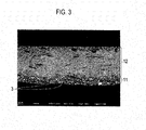
- Fig. 3 shows an image obtained by observation of a cross-section of the positive electrode sheet of Example 2 by a scanning electron microscope.
- Example 3 The same operation as that of Example 2 was repeated, thus providing a positive electrode sheet. Next, polyvinylidene fluoride solution was applied to metal mesh. The metal mesh was bonded to the fluid-tight gas-permeable layer side of the positive electrode sheet, followed by drying, thus providing a positive electrode sheet of Example 3.
- the metal mesh used herein was made of gold-plated SUS304 and had 200 meshes.
- Wire mesh (200 meshes) was used as the current collector.
- the current collector was pressed with powder mixture of constituent materials shown in Table 1 below into the catalyst layer.
- the obtained catalyst layer and a commercially-available PTFE sheet for air cells were hot-pressed at 330°C, thus providing a positive electrode of Comparative Example 1.
- the positive electrode sheets of Examples 1 to 3 and Comparative Example 1 were used to make beaker cells in which the opposed electrode was a zinc plate (made by Nilaco Corporation) and the electrolysis solution was 8 N potassium hydroxide solution for discharge evaluation.
- Table 2 shows the results of comparison between outputs from the positive electrode sheets for current density per unit area of the positive electrode sheet. [Table 2] OUTPUT at 100 mA/cm 2 (W/cm 2 ) EXAMPLE 1 0.12 EXAMPLE 2 0.14 EXAMPLE 3 0.15 COMPARATIVE EXAMPLE 1 0.1
- Positive electrode sheets of Examples 4 to 8 were provided by repeating the same operation as that of Example 1 other than the constituent materials of the fluid-tight gas-permeable layer and the contents thereof.
- the constituent materials and the contents thereof in the fluid-tight gas-permeable layer of each example are shown in Table 3.
- Table 3 also shows the constituent materials and contents thereof in the fluid-tight gas-permeable layers of Examples 1 to 3 and Comparative Example 1 together for reference.
- Table 3 also shows the thicknesses of the positive electrode sheets of Examples 1 to 8 and Comparative Example 1.
- CNF carbon nanofibers, which had a diameter of 40 nm to 90 nm and an aspect ratio of 1000 or more.
- VGCF represents vapor grown carbon fibers, which had a diameter of 150 nm and a fiber length of 10 ⁇ m to 20 ⁇ m.
- the positive electrode sheet of each example is subjected to measurement of tensile strength in accordance with JIS 7161. The obtained results are shown in Table 3.
- the positive electrode sheets of Examples 1 to 3 and Comparative Example 1 are also subjected to measurement of tensile strength in a similar manner.
- the positive electrode sheets obtained in Examples 1 to 8 and Comparative Example 1 were cut into a diameter of 20 mm for measurement of contact resistance.
- the device for the measurement was a contact resistance meter.
- Each of the positive electrode sheets between two electrodes was sandwiched and was subjected to measurement of penetration resistance values (m ⁇ cm 2 ) when current of 1 A/cm 2 was applied at a measurement surface pressure of 2.0 MPa.
- the penetration resistance represents an electrical resistance value in the vertical direction to the sheet surface. As the penetration resistance lowers, the discharge loss can be reduced.
- Table 3 The obtained results are shown Table 3.
- Example 5 whose thickness is a half of the thickness of Example 4, achieved the same tensile strength. As the thickness of the positive electrode gets smaller, the resistance lowers, and the positive electrode can provide higher output power.
- the positive electrode for air cells of the present invention is produced by stacking the catalyst layer and fluid-tight gas-permeable layer which are formed by using the electrical conductive carbon and binders. This can prevent leakage of the electrolysis solution from the positive electrode while facilitating series connection of the air cells and increasing the manufacturing efficiency and handleability.
Landscapes
- Chemical & Material Sciences (AREA)
- Chemical Kinetics & Catalysis (AREA)
- Electrochemistry (AREA)
- General Chemical & Material Sciences (AREA)
- Engineering & Computer Science (AREA)
- Manufacturing & Machinery (AREA)
- Mechanical Engineering (AREA)
- Composite Materials (AREA)
- Physics & Mathematics (AREA)
- Thermal Sciences (AREA)
- Hybrid Cells (AREA)
- Inert Electrodes (AREA)
Applications Claiming Priority (3)
| Application Number | Priority Date | Filing Date | Title |
|---|---|---|---|
| JP2012094529 | 2012-04-18 | ||
| JP2013043660A JP6229994B2 (ja) | 2012-04-18 | 2013-03-06 | 空気電池用正極及びその製造方法 |
| PCT/JP2013/056419 WO2013157317A1 (ja) | 2012-04-18 | 2013-03-08 | 空気電池用正極及びその製造方法 |
Publications (3)
| Publication Number | Publication Date |
|---|---|
| EP2840645A1 true EP2840645A1 (de) | 2015-02-25 |
| EP2840645A4 EP2840645A4 (de) | 2015-04-08 |
| EP2840645B1 EP2840645B1 (de) | 2017-05-10 |
Family
ID=49383285
Family Applications (1)
| Application Number | Title | Priority Date | Filing Date |
|---|---|---|---|
| EP13778564.8A Active EP2840645B1 (de) | 2012-04-18 | 2013-03-08 | Positive elektrode für luftbatterie und verfahren zur herstellung davon |
Country Status (6)
| Country | Link |
|---|---|
| US (1) | US10147954B2 (de) |
| EP (1) | EP2840645B1 (de) |
| JP (1) | JP6229994B2 (de) |
| CN (1) | CN104221213B (de) |
| TW (1) | TWI470866B (de) |
| WO (1) | WO2013157317A1 (de) |
Families Citing this family (12)
| Publication number | Priority date | Publication date | Assignee | Title |
|---|---|---|---|---|
| JP5559927B1 (ja) * | 2013-12-25 | 2014-07-23 | 日本協能電子株式会社 | 空気マグネシウム電池 |
| JP6441900B2 (ja) * | 2014-03-28 | 2018-12-19 | 日本碍子株式会社 | 金属空気電池用空気極 |
| JP6305192B2 (ja) * | 2014-04-25 | 2018-04-04 | 日本協能電子株式会社 | 空気マグネシウム電池 |
| JP6241946B2 (ja) * | 2014-09-19 | 2017-12-06 | 日本電信電話株式会社 | リチウム空気電池用空気極の製造方法 |
| JP6459034B2 (ja) * | 2014-10-01 | 2019-01-30 | 日産自動車株式会社 | 空気電池用正極及びその製造方法 |
| KR102475889B1 (ko) * | 2015-10-13 | 2022-12-08 | 삼성전자주식회사 | 금속 공기 전지 |
| JP6728776B2 (ja) * | 2016-03-02 | 2020-07-22 | 日立化成株式会社 | 触媒組成物、有機廃水処理装置用電極及び有機廃水処理装置 |
| JP2018063832A (ja) * | 2016-10-12 | 2018-04-19 | Tdk株式会社 | マグネシウム空気電池用正極およびマグネシウム空気電池 |
| EP3850690A4 (de) * | 2018-09-12 | 2022-08-10 | IFBattery Inc. | Reihe von zellen zur verwendung in einer elektrochemischen vorrichtung |
| WO2020087119A1 (en) * | 2018-10-29 | 2020-05-07 | Newsouth Innovations Pty Limited | Hydrogen-based battery |
| CN109860633B (zh) * | 2019-02-13 | 2021-10-08 | 苏州擎动动力科技有限公司 | 一种有序介孔催化层及膜电极的制备方法和用途 |
| EP4681278A1 (de) * | 2023-03-14 | 2026-01-21 | Polyjoule, Inc. | Monolithische elektroden mit hoher last |
Family Cites Families (21)
| Publication number | Priority date | Publication date | Assignee | Title |
|---|---|---|---|---|
| US4828939A (en) * | 1987-06-01 | 1989-05-09 | Eltech Systems Corporation | Bipolar metal/air battery |
| JPH06267594A (ja) * | 1993-03-15 | 1994-09-22 | Matsushita Electric Ind Co Ltd | 空気電池 |
| US5432022A (en) * | 1993-11-12 | 1995-07-11 | Dreisbach Electromotive Inc. | Coated cathode for rechargeable metal battery |
| JPH07211322A (ja) * | 1994-01-25 | 1995-08-11 | Matsushita Electric Ind Co Ltd | 空気電極及びその製造方法並びにその電極を有する空気電池 |
| JP3854682B2 (ja) * | 1997-02-13 | 2006-12-06 | アイシン高丘株式会社 | 燃料電池用セパレータ |
| JP3557860B2 (ja) | 1997-07-31 | 2004-08-25 | 松下電器産業株式会社 | 空気電池用空気極およびその空気電池用空気極の製造法 |
| US6127060A (en) * | 1998-06-17 | 2000-10-03 | Aer Energy Resources, Inc. | Recharge catalyst with thin film low corrosion coating, metal-air electrode including said catalyst and methods for making said catalyst and electrode |
| CN1533618A (zh) | 2002-03-14 | 2004-09-29 | ���µ�����ҵ��ʽ���� | 制造聚合物电解质型燃料电池的方法和聚合物电解质膜型燃料电池 |
| JP4837298B2 (ja) * | 2005-03-10 | 2011-12-14 | 日本ゴア株式会社 | 湿度調整フィルム |
| JP2007214114A (ja) * | 2006-01-12 | 2007-08-23 | Matsushita Electric Ind Co Ltd | 空気電池および空気電池用空気極の製造方法 |
| US20070160898A1 (en) * | 2006-01-12 | 2007-07-12 | Matsushita Electric Industrial Co., Ltd. | Air battery and method for producing air electrode for air battery |
| CN200941417Y (zh) * | 2006-08-24 | 2007-08-29 | 比亚迪股份有限公司 | 一种锌空气电池 |
| WO2008058165A2 (en) * | 2006-11-06 | 2008-05-15 | Akermin, Inc. | Bioanode and biocathode stack assemblies |
| JP2010516017A (ja) * | 2007-01-05 | 2010-05-13 | アケルミン・インコーポレイテッド | バイオアノード及びバイオカソードのスタックアセンブリ |
| JP4458117B2 (ja) * | 2007-06-01 | 2010-04-28 | 株式会社豊田中央研究所 | 非水系空気電池及びその触媒 |
| JP4911155B2 (ja) * | 2008-10-08 | 2012-04-04 | トヨタ自動車株式会社 | 電池電極の製造方法 |
| CN101908661B (zh) * | 2009-06-03 | 2013-02-20 | 北京中航长力能源科技有限公司 | 一种圆柱式锌空气电池的密封方法 |
| WO2011074122A1 (ja) * | 2009-12-18 | 2011-06-23 | トヨタ自動車株式会社 | 空気電池用空気極、及び、当該空気極を備えた空気電池 |
| US20110236799A1 (en) * | 2010-02-12 | 2011-09-29 | Revolt Technology Ltd. | Manufacturing methods for air electrode |
| JP2011181374A (ja) * | 2010-03-02 | 2011-09-15 | Mitsubishi Electric Corp | 固体高分子形燃料電池用膜電極接合体および固体高分子形燃料電池 |
| US20120021303A1 (en) * | 2010-07-21 | 2012-01-26 | Steven Amendola | Electrically rechargeable, metal-air battery systems and methods |
-
2013
- 2013-03-06 JP JP2013043660A patent/JP6229994B2/ja active Active
- 2013-03-08 EP EP13778564.8A patent/EP2840645B1/de active Active
- 2013-03-08 CN CN201380020116.5A patent/CN104221213B/zh active Active
- 2013-03-08 WO PCT/JP2013/056419 patent/WO2013157317A1/ja not_active Ceased
- 2013-03-08 US US14/394,175 patent/US10147954B2/en active Active
- 2013-03-08 TW TW102108231A patent/TWI470866B/zh active
Also Published As
| Publication number | Publication date |
|---|---|
| TW201401634A (zh) | 2014-01-01 |
| EP2840645B1 (de) | 2017-05-10 |
| CN104221213A (zh) | 2014-12-17 |
| EP2840645A4 (de) | 2015-04-08 |
| CN104221213B (zh) | 2017-12-05 |
| US20150086883A1 (en) | 2015-03-26 |
| TWI470866B (zh) | 2015-01-21 |
| JP2013239428A (ja) | 2013-11-28 |
| US10147954B2 (en) | 2018-12-04 |
| JP6229994B2 (ja) | 2017-11-15 |
| WO2013157317A1 (ja) | 2013-10-24 |
Similar Documents
| Publication | Publication Date | Title |
|---|---|---|
| EP2840645B1 (de) | Positive elektrode für luftbatterie und verfahren zur herstellung davon | |
| JP5924530B2 (ja) | 燃料電池用ガス拡散層 | |
| RU2556237C1 (ru) | Элемент с воздушной деполяризацией и собранная батарея с его использованием | |
| JP5839161B2 (ja) | 燃料電池用ガス拡散層及びその製造方法 | |
| US20110171563A1 (en) | Gas diffusion layer for fuel cell | |
| JP7218263B2 (ja) | 積層触媒、電極、膜電極複合体、電気化学セル、スタック、燃料電池及び水電解の可逆装置、車両及び飛翔体 | |
| CN107681190B (zh) | 一种高电压电池的双极性结构体及电芯 | |
| JP6350893B2 (ja) | 空気電池用正極の製造方法 | |
| WO2011074327A1 (ja) | 燃料電池用ガス拡散層及びこれを用いた膜電極接合体 | |
| JP6119865B2 (ja) | 空気電池及び組電池 | |
| JP4475866B2 (ja) | 燃料電池 | |
| CN1649690A (zh) | 燃料电池或者电解槽的多孔金属叠板 | |
| US10818931B2 (en) | Air electrode material, air electrode, metal-air battery, and fuel cell | |
| WO2014010382A1 (ja) | 気体透過シート | |
| JP2014175285A (ja) | ガス拡散層、膜電極接合体、燃料電池、及びガス拡散層の製造方法 | |
| JP6434691B2 (ja) | 空気電池用正極及びその製造方法 |
Legal Events
| Date | Code | Title | Description |
|---|---|---|---|
| PUAI | Public reference made under article 153(3) epc to a published international application that has entered the european phase |
Free format text: ORIGINAL CODE: 0009012 |
|
| 17P | Request for examination filed |
Effective date: 20141114 |
|
| AK | Designated contracting states |
Kind code of ref document: A1 Designated state(s): AL AT BE BG CH CY CZ DE DK EE ES FI FR GB GR HR HU IE IS IT LI LT LU LV MC MK MT NL NO PL PT RO RS SE SI SK SM TR |
|
| AX | Request for extension of the european patent |
Extension state: BA ME |
|
| RA4 | Supplementary search report drawn up and despatched (corrected) |
Effective date: 20150311 |
|
| RIC1 | Information provided on ipc code assigned before grant |
Ipc: H01M 4/88 20060101ALI20150305BHEP Ipc: H01M 4/96 20060101ALI20150305BHEP Ipc: H01M 12/08 20060101ALI20150305BHEP Ipc: H01M 12/06 20060101AFI20150305BHEP |
|
| DAX | Request for extension of the european patent (deleted) | ||
| 17Q | First examination report despatched |
Effective date: 20160408 |
|
| GRAP | Despatch of communication of intention to grant a patent |
Free format text: ORIGINAL CODE: EPIDOSNIGR1 |
|
| INTG | Intention to grant announced |
Effective date: 20170117 |
|
| GRAS | Grant fee paid |
Free format text: ORIGINAL CODE: EPIDOSNIGR3 |
|
| GRAA | (expected) grant |
Free format text: ORIGINAL CODE: 0009210 |
|
| AK | Designated contracting states |
Kind code of ref document: B1 Designated state(s): AL AT BE BG CH CY CZ DE DK EE ES FI FR GB GR HR HU IE IS IT LI LT LU LV MC MK MT NL NO PL PT RO RS SE SI SK SM TR |
|
| REG | Reference to a national code |
Ref country code: GB Ref legal event code: FG4D |
|
| REG | Reference to a national code |
Ref country code: AT Ref legal event code: REF Ref document number: 893205 Country of ref document: AT Kind code of ref document: T Effective date: 20170515 Ref country code: CH Ref legal event code: EP |
|
| REG | Reference to a national code |
Ref country code: IE Ref legal event code: FG4D |
|
| REG | Reference to a national code |
Ref country code: DE Ref legal event code: R096 Ref document number: 602013021017 Country of ref document: DE |
|
| REG | Reference to a national code |
Ref country code: NL Ref legal event code: MP Effective date: 20170510 |
|
| REG | Reference to a national code |
Ref country code: LT Ref legal event code: MG4D |
|
| REG | Reference to a national code |
Ref country code: AT Ref legal event code: MK05 Ref document number: 893205 Country of ref document: AT Kind code of ref document: T Effective date: 20170510 |
|
| PG25 | Lapsed in a contracting state [announced via postgrant information from national office to epo] |
Ref country code: GR Free format text: LAPSE BECAUSE OF FAILURE TO SUBMIT A TRANSLATION OF THE DESCRIPTION OR TO PAY THE FEE WITHIN THE PRESCRIBED TIME-LIMIT Effective date: 20170811 Ref country code: FI Free format text: LAPSE BECAUSE OF FAILURE TO SUBMIT A TRANSLATION OF THE DESCRIPTION OR TO PAY THE FEE WITHIN THE PRESCRIBED TIME-LIMIT Effective date: 20170510 Ref country code: AT Free format text: LAPSE BECAUSE OF FAILURE TO SUBMIT A TRANSLATION OF THE DESCRIPTION OR TO PAY THE FEE WITHIN THE PRESCRIBED TIME-LIMIT Effective date: 20170510 Ref country code: LT Free format text: LAPSE BECAUSE OF FAILURE TO SUBMIT A TRANSLATION OF THE DESCRIPTION OR TO PAY THE FEE WITHIN THE PRESCRIBED TIME-LIMIT Effective date: 20170510 Ref country code: ES Free format text: LAPSE BECAUSE OF FAILURE TO SUBMIT A TRANSLATION OF THE DESCRIPTION OR TO PAY THE FEE WITHIN THE PRESCRIBED TIME-LIMIT Effective date: 20170510 Ref country code: NO Free format text: LAPSE BECAUSE OF FAILURE TO SUBMIT A TRANSLATION OF THE DESCRIPTION OR TO PAY THE FEE WITHIN THE PRESCRIBED TIME-LIMIT Effective date: 20170810 Ref country code: HR Free format text: LAPSE BECAUSE OF FAILURE TO SUBMIT A TRANSLATION OF THE DESCRIPTION OR TO PAY THE FEE WITHIN THE PRESCRIBED TIME-LIMIT Effective date: 20170510 |
|
| PG25 | Lapsed in a contracting state [announced via postgrant information from national office to epo] |
Ref country code: SE Free format text: LAPSE BECAUSE OF FAILURE TO SUBMIT A TRANSLATION OF THE DESCRIPTION OR TO PAY THE FEE WITHIN THE PRESCRIBED TIME-LIMIT Effective date: 20170510 Ref country code: RS Free format text: LAPSE BECAUSE OF FAILURE TO SUBMIT A TRANSLATION OF THE DESCRIPTION OR TO PAY THE FEE WITHIN THE PRESCRIBED TIME-LIMIT Effective date: 20170510 Ref country code: NL Free format text: LAPSE BECAUSE OF FAILURE TO SUBMIT A TRANSLATION OF THE DESCRIPTION OR TO PAY THE FEE WITHIN THE PRESCRIBED TIME-LIMIT Effective date: 20170510 Ref country code: IS Free format text: LAPSE BECAUSE OF FAILURE TO SUBMIT A TRANSLATION OF THE DESCRIPTION OR TO PAY THE FEE WITHIN THE PRESCRIBED TIME-LIMIT Effective date: 20170910 Ref country code: PL Free format text: LAPSE BECAUSE OF FAILURE TO SUBMIT A TRANSLATION OF THE DESCRIPTION OR TO PAY THE FEE WITHIN THE PRESCRIBED TIME-LIMIT Effective date: 20170510 Ref country code: BG Free format text: LAPSE BECAUSE OF FAILURE TO SUBMIT A TRANSLATION OF THE DESCRIPTION OR TO PAY THE FEE WITHIN THE PRESCRIBED TIME-LIMIT Effective date: 20170810 Ref country code: LV Free format text: LAPSE BECAUSE OF FAILURE TO SUBMIT A TRANSLATION OF THE DESCRIPTION OR TO PAY THE FEE WITHIN THE PRESCRIBED TIME-LIMIT Effective date: 20170510 |
|
| PG25 | Lapsed in a contracting state [announced via postgrant information from national office to epo] |
Ref country code: RO Free format text: LAPSE BECAUSE OF FAILURE TO SUBMIT A TRANSLATION OF THE DESCRIPTION OR TO PAY THE FEE WITHIN THE PRESCRIBED TIME-LIMIT Effective date: 20170510 Ref country code: CZ Free format text: LAPSE BECAUSE OF FAILURE TO SUBMIT A TRANSLATION OF THE DESCRIPTION OR TO PAY THE FEE WITHIN THE PRESCRIBED TIME-LIMIT Effective date: 20170510 Ref country code: SK Free format text: LAPSE BECAUSE OF FAILURE TO SUBMIT A TRANSLATION OF THE DESCRIPTION OR TO PAY THE FEE WITHIN THE PRESCRIBED TIME-LIMIT Effective date: 20170510 Ref country code: EE Free format text: LAPSE BECAUSE OF FAILURE TO SUBMIT A TRANSLATION OF THE DESCRIPTION OR TO PAY THE FEE WITHIN THE PRESCRIBED TIME-LIMIT Effective date: 20170510 Ref country code: DK Free format text: LAPSE BECAUSE OF FAILURE TO SUBMIT A TRANSLATION OF THE DESCRIPTION OR TO PAY THE FEE WITHIN THE PRESCRIBED TIME-LIMIT Effective date: 20170510 |
|
| REG | Reference to a national code |
Ref country code: DE Ref legal event code: R097 Ref document number: 602013021017 Country of ref document: DE |
|
| REG | Reference to a national code |
Ref country code: FR Ref legal event code: PLFP Year of fee payment: 6 |
|
| PG25 | Lapsed in a contracting state [announced via postgrant information from national office to epo] |
Ref country code: IT Free format text: LAPSE BECAUSE OF FAILURE TO SUBMIT A TRANSLATION OF THE DESCRIPTION OR TO PAY THE FEE WITHIN THE PRESCRIBED TIME-LIMIT Effective date: 20170510 Ref country code: SM Free format text: LAPSE BECAUSE OF FAILURE TO SUBMIT A TRANSLATION OF THE DESCRIPTION OR TO PAY THE FEE WITHIN THE PRESCRIBED TIME-LIMIT Effective date: 20170510 |
|
| PLBE | No opposition filed within time limit |
Free format text: ORIGINAL CODE: 0009261 |
|
| STAA | Information on the status of an ep patent application or granted ep patent |
Free format text: STATUS: NO OPPOSITION FILED WITHIN TIME LIMIT |
|
| 26N | No opposition filed |
Effective date: 20180213 |
|
| PG25 | Lapsed in a contracting state [announced via postgrant information from national office to epo] |
Ref country code: SI Free format text: LAPSE BECAUSE OF FAILURE TO SUBMIT A TRANSLATION OF THE DESCRIPTION OR TO PAY THE FEE WITHIN THE PRESCRIBED TIME-LIMIT Effective date: 20170510 |
|
| REG | Reference to a national code |
Ref country code: CH Ref legal event code: PL |
|
| PG25 | Lapsed in a contracting state [announced via postgrant information from national office to epo] |
Ref country code: MC Free format text: LAPSE BECAUSE OF FAILURE TO SUBMIT A TRANSLATION OF THE DESCRIPTION OR TO PAY THE FEE WITHIN THE PRESCRIBED TIME-LIMIT Effective date: 20170510 |
|
| REG | Reference to a national code |
Ref country code: BE Ref legal event code: MM Effective date: 20180331 |
|
| REG | Reference to a national code |
Ref country code: IE Ref legal event code: MM4A |
|
| PG25 | Lapsed in a contracting state [announced via postgrant information from national office to epo] |
Ref country code: LU Free format text: LAPSE BECAUSE OF NON-PAYMENT OF DUE FEES Effective date: 20180308 |
|
| PG25 | Lapsed in a contracting state [announced via postgrant information from national office to epo] |
Ref country code: IE Free format text: LAPSE BECAUSE OF NON-PAYMENT OF DUE FEES Effective date: 20180308 |
|
| PG25 | Lapsed in a contracting state [announced via postgrant information from national office to epo] |
Ref country code: CH Free format text: LAPSE BECAUSE OF NON-PAYMENT OF DUE FEES Effective date: 20180331 Ref country code: LI Free format text: LAPSE BECAUSE OF NON-PAYMENT OF DUE FEES Effective date: 20180331 Ref country code: BE Free format text: LAPSE BECAUSE OF NON-PAYMENT OF DUE FEES Effective date: 20180331 |
|
| PG25 | Lapsed in a contracting state [announced via postgrant information from national office to epo] |
Ref country code: MT Free format text: LAPSE BECAUSE OF NON-PAYMENT OF DUE FEES Effective date: 20180308 |
|
| PG25 | Lapsed in a contracting state [announced via postgrant information from national office to epo] |
Ref country code: TR Free format text: LAPSE BECAUSE OF FAILURE TO SUBMIT A TRANSLATION OF THE DESCRIPTION OR TO PAY THE FEE WITHIN THE PRESCRIBED TIME-LIMIT Effective date: 20170510 |
|
| PG25 | Lapsed in a contracting state [announced via postgrant information from national office to epo] |
Ref country code: PT Free format text: LAPSE BECAUSE OF FAILURE TO SUBMIT A TRANSLATION OF THE DESCRIPTION OR TO PAY THE FEE WITHIN THE PRESCRIBED TIME-LIMIT Effective date: 20170510 |
|
| PG25 | Lapsed in a contracting state [announced via postgrant information from national office to epo] |
Ref country code: CY Free format text: LAPSE BECAUSE OF FAILURE TO SUBMIT A TRANSLATION OF THE DESCRIPTION OR TO PAY THE FEE WITHIN THE PRESCRIBED TIME-LIMIT Effective date: 20170510 Ref country code: MK Free format text: LAPSE BECAUSE OF NON-PAYMENT OF DUE FEES Effective date: 20170510 Ref country code: HU Free format text: LAPSE BECAUSE OF FAILURE TO SUBMIT A TRANSLATION OF THE DESCRIPTION OR TO PAY THE FEE WITHIN THE PRESCRIBED TIME-LIMIT; INVALID AB INITIO Effective date: 20130308 |
|
| PG25 | Lapsed in a contracting state [announced via postgrant information from national office to epo] |
Ref country code: AL Free format text: LAPSE BECAUSE OF FAILURE TO SUBMIT A TRANSLATION OF THE DESCRIPTION OR TO PAY THE FEE WITHIN THE PRESCRIBED TIME-LIMIT Effective date: 20170510 |
|
| PGFP | Annual fee paid to national office [announced via postgrant information from national office to epo] |
Ref country code: GB Payment date: 20260220 Year of fee payment: 14 |
|
| PGFP | Annual fee paid to national office [announced via postgrant information from national office to epo] |
Ref country code: DE Payment date: 20260219 Year of fee payment: 14 |
|
| PGFP | Annual fee paid to national office [announced via postgrant information from national office to epo] |
Ref country code: FR Payment date: 20260219 Year of fee payment: 14 |