EP2841823B1 - Joint à cadre support à encombrement réduit - Google Patents
Joint à cadre support à encombrement réduit Download PDFInfo
- Publication number
- EP2841823B1 EP2841823B1 EP12795402.2A EP12795402A EP2841823B1 EP 2841823 B1 EP2841823 B1 EP 2841823B1 EP 12795402 A EP12795402 A EP 12795402A EP 2841823 B1 EP2841823 B1 EP 2841823B1
- Authority
- EP
- European Patent Office
- Prior art keywords
- support frame
- ring
- sealing
- seal according
- sealing profile
- Prior art date
- Legal status (The legal status is an assumption and is not a legal conclusion. Google has not performed a legal analysis and makes no representation as to the accuracy of the status listed.)
- Not-in-force
Links
- 238000007789 sealing Methods 0.000 claims description 111
- 239000000463 material Substances 0.000 claims description 21
- 229920001971 elastomer Polymers 0.000 claims description 20
- 239000000806 elastomer Substances 0.000 claims description 20
- 238000001746 injection moulding Methods 0.000 claims description 8
- 229910052751 metal Inorganic materials 0.000 claims description 5
- 239000002184 metal Substances 0.000 claims description 5
- 230000001419 dependent effect Effects 0.000 claims 2
- 238000004519 manufacturing process Methods 0.000 description 17
- 238000004080 punching Methods 0.000 description 16
- 238000002347 injection Methods 0.000 description 8
- 239000007924 injection Substances 0.000 description 8
- 238000000034 method Methods 0.000 description 7
- 239000000243 solution Substances 0.000 description 6
- 230000006835 compression Effects 0.000 description 5
- 238000007906 compression Methods 0.000 description 5
- 239000013536 elastomeric material Substances 0.000 description 5
- 230000008569 process Effects 0.000 description 5
- 229910052782 aluminium Inorganic materials 0.000 description 4
- XAGFODPZIPBFFR-UHFFFAOYSA-N aluminium Chemical compound [Al] XAGFODPZIPBFFR-UHFFFAOYSA-N 0.000 description 4
- 230000008901 benefit Effects 0.000 description 4
- 229910000831 Steel Inorganic materials 0.000 description 3
- 239000012050 conventional carrier Substances 0.000 description 3
- 230000000694 effects Effects 0.000 description 3
- 238000000465 moulding Methods 0.000 description 3
- 239000010959 steel Substances 0.000 description 3
- 238000004026 adhesive bonding Methods 0.000 description 2
- 238000007373 indentation Methods 0.000 description 2
- 238000003825 pressing Methods 0.000 description 2
- 230000009467 reduction Effects 0.000 description 2
- 125000006850 spacer group Chemical group 0.000 description 2
- 230000007704 transition Effects 0.000 description 2
- 238000004073 vulcanization Methods 0.000 description 2
- 229910001369 Brass Inorganic materials 0.000 description 1
- 230000000712 assembly Effects 0.000 description 1
- 238000000429 assembly Methods 0.000 description 1
- 239000010951 brass Substances 0.000 description 1
- 230000008859 change Effects 0.000 description 1
- 238000010276 construction Methods 0.000 description 1
- 238000009760 electrical discharge machining Methods 0.000 description 1
- 238000004049 embossing Methods 0.000 description 1
- 238000001125 extrusion Methods 0.000 description 1
- 210000004907 gland Anatomy 0.000 description 1
- 238000003698 laser cutting Methods 0.000 description 1
- 238000003754 machining Methods 0.000 description 1
- 230000007246 mechanism Effects 0.000 description 1
- 238000004806 packaging method and process Methods 0.000 description 1
- 238000001259 photo etching Methods 0.000 description 1
- 238000000926 separation method Methods 0.000 description 1
- 239000011343 solid material Substances 0.000 description 1
- 239000012086 standard solution Substances 0.000 description 1
- 238000007514 turning Methods 0.000 description 1
- 239000013585 weight reducing agent Substances 0.000 description 1
- 238000003466 welding Methods 0.000 description 1
Images


Classifications
-
- F—MECHANICAL ENGINEERING; LIGHTING; HEATING; WEAPONS; BLASTING
- F16—ENGINEERING ELEMENTS AND UNITS; GENERAL MEASURES FOR PRODUCING AND MAINTAINING EFFECTIVE FUNCTIONING OF MACHINES OR INSTALLATIONS; THERMAL INSULATION IN GENERAL
- F16J—PISTONS; CYLINDERS; SEALINGS
- F16J15/00—Sealings
- F16J15/02—Sealings between relatively-stationary surfaces
- F16J15/06—Sealings between relatively-stationary surfaces with solid packing compressed between sealing surfaces
- F16J15/10—Sealings between relatively-stationary surfaces with solid packing compressed between sealing surfaces with non-metallic packing
- F16J15/12—Sealings between relatively-stationary surfaces with solid packing compressed between sealing surfaces with non-metallic packing with metal reinforcement or covering
- F16J15/121—Sealings between relatively-stationary surfaces with solid packing compressed between sealing surfaces with non-metallic packing with metal reinforcement or covering with metal reinforcement
- F16J15/122—Sealings between relatively-stationary surfaces with solid packing compressed between sealing surfaces with non-metallic packing with metal reinforcement or covering with metal reinforcement generally parallel to the surfaces
-
- F—MECHANICAL ENGINEERING; LIGHTING; HEATING; WEAPONS; BLASTING
- F16—ENGINEERING ELEMENTS AND UNITS; GENERAL MEASURES FOR PRODUCING AND MAINTAINING EFFECTIVE FUNCTIONING OF MACHINES OR INSTALLATIONS; THERMAL INSULATION IN GENERAL
- F16J—PISTONS; CYLINDERS; SEALINGS
- F16J15/00—Sealings
- F16J15/02—Sealings between relatively-stationary surfaces
- F16J15/06—Sealings between relatively-stationary surfaces with solid packing compressed between sealing surfaces
- F16J15/10—Sealings between relatively-stationary surfaces with solid packing compressed between sealing surfaces with non-metallic packing
- F16J15/12—Sealings between relatively-stationary surfaces with solid packing compressed between sealing surfaces with non-metallic packing with metal reinforcement or covering
- F16J15/121—Sealings between relatively-stationary surfaces with solid packing compressed between sealing surfaces with non-metallic packing with metal reinforcement or covering with metal reinforcement
- F16J15/127—Sealings between relatively-stationary surfaces with solid packing compressed between sealing surfaces with non-metallic packing with metal reinforcement or covering with metal reinforcement the reinforcement being a compression stopper
Definitions
- the present invention relates to girder seals, as used for housing parts with sealing surfaces such as covers or hoods, which are attached to other machine parts.
- the present invention preferably relates to use with carrier frame gaskets.
- the present invention relates in particular to a design in which a sealing profile made of elastomer is vulcanized on the end face of a support frame.
- This embodiment has the advantage that one uses a support frame such as an aluminum support frame once as a support frame for the sealing profile and this also serves as Wegbegrenzer or Verpressungsbegrenzer for the elastomeric seal and additionally absorbs the Verschraubungs characteristic.
- the support frame acts here as Verpressungsbeskyr, so that the seal is in the force shunt.
- the flange on which the gasket is to be mounted has a sufficient width, i. There is enough room for both the sealing profile and sufficient support surface for the support frame available.
- the support frames for such seals are made almost exclusively by stamping, as this is the least expensive option to manufacture.
- Critical locations of a girder seal relative to the flange widths are generally the areas around glands. The reason for this is that, apart from the opening in the support frame through which the screw is guided, the support frame must be guided past inside and outside of the screw, so that in turn results in a closed bore.
- Known special solutions are specified in the prior art.
- the state of the art and also the simplest implementation of these areas in a sealing solution are given if the flange surface of both components provides sufficient width and coverage in all areas. In these cases, it is not necessary to go to the manufacturability limits of the support frame and the bypasses in the region of the screw holes have both outside and inside a sufficient support frame width.
- the flange surface also provides sufficient space to allow two sealing lips to be guided around the threaded connection area, which then rest securely on the two flange sides within all tolerance positions, with the sealing lips in secure contact with both flanges.
- the minimum web width which can be sensibly produced by punching, is approximately at a ratio of 2 to 1. This means that a web must be made at least twice as wide like the thickness of the sheet into which the web is punched. If the carrier sheet is, for example, 1.5 mm thick, the web must be about 3 mm wide, so that it can still be clamped and punched well in the punching tool without major deformations of the web occurring. In many parts, this limit is now undercut and taken into account the disadvantages described below.
- a further reduction of the range of travel would be necessary in order to have a solution for these problem areas at all.
- a narrower deflection of the screw opening on the support frame can only be reduced below the reasonable level, if other disadvantages are accepted. If the width of the web down to a square cross-section (eg support sheet thickness 1.5mm and web width 1.5mm) is reduced, the web is deformed during punching, and it formed by the punching induced indentations and the web can also rotate. The result of the punching in the area is then no longer clearly geometrically predictable. Apart from the deformation, the stiffness of the support frame is greatly affected by these thin webs, which can lead to serious disadvantages when molding the elastomeric seal, since the injection pressure during manufacture can bend the web. Inserting pins in the tool at the holes to limit the deformation of the frame, they can jam and when removing from the mold again around the thin webs bend.
- a punch is a deformation of the sheet edge on a punching line. Punch feeds prevent the carrier frame from being optimally clamped in the injection mold, which may result in over-molding of elastomeric material on the carrier frame and in the screw holes, which is unacceptable.
- Another problem is that due to the insufficient impression, the elastomer material can run into the bore, which then has to be laboriously cleaned again by hand.
- a carrier frame seal is provided with a reduced footprint.
- the carrier frame seal comprises a support frame and a sealing profile made of an elastomeric material which is dull on one end face a support frame is vulcanized.
- the support frame further has recesses for fastening elements. At at least one recess of the support frame on the side at which the sealing profile is vulcanized is interrupted, and extends only on the opposite side of the sealing profile of the at least one recess.
- the support frame is provided on the at least one recess with a ring or with a ring element.
- the ring or the ring element is intended to surround a fastener which is to pass through the recess.
- the ring or the ring element lies in the plane of the support frame.
- the through hole for fixing screws is open through the support frame toward the side of the elastomeric seal.
- the through hole for fastening screws in the support frame has been expanded in this embodiment to a semi-open recess.
- the open side of the recess in the support frame is closed by the ring or the ring member.
- the vulcanized elastomer closes any transitions between the ring or the ring element and the sealing profile.
- the ring has a wall thickness that is less than a width of a ridge that can be stamped into the carrier frame without warping the material of the carrier frame, indenting, or allowing the remaining ridge to twist during punching.
- the ring need not be made by punching, and therefore may have a cross section that can not be achieved with punching.
- the wall thickness of the ring in the radial direction may be smaller than the thickness of the ring in the axial direction.
- the wall thickness of the ring in the radial direction may be less than half as small as the thickness of the ring in the axial direction.
- a material made from the ring has a higher strength than a material from which the carrier frame is made. This can also be achieved that the ring does not bend during operation. It can also be prevented that the ring is bent or destroyed during injection / vulcanization of the sealing profile of the ring.
- a ring of solid material also makes it possible during injection / vulcanization of the sealing profile to ensure that no elastomer material runs into the ring or into a screw leadthrough or the recess.
- At least one further of the recesses is bypassed by the sealing profile, wherein the sealing profile is reduced in the region of at least one deflection in the width.
- This embodiment relates to a seal with an open or ring-shaped recess which is bypassed by a sealing profile which is reduced in width.
- the sealing profile has a sealing lip in the region of the at least one bypass or the recess or ring open on one side, whereas the sealing profile in regions outside the at least one bypass of the recess or ring open on one side Having sealing lips which run side by side.
- the sealing profile has a sealing lip in the region of the at least one bypass, while the sealing profile has two sealing lips in regions outside the at least one bypass which run next to one another.
- sealing profiles with more than two, ie three or more sealing lips in areas outside the at least one bypass.
- two or more sealing lips are present in the remaining flange, in the region of the screw eyes, the number of sealing lips reduced to one.
- two or more sealing lips in the area around a bypass to a single sealing lip can be merged, which diverge after passing around again in two sealing lips. Merging the sealing lips into a single in the area of Fastening protrudes from technically justifiable, since at this point minimal tolerances with optimal compression force are present.
- the one sealing lip is made wider than each of the two adjacent two or more sealing lips.
- the at least one ring is not round outside.
- a square on the outside or oval shape of the ring can help fix the ring better in the carrier layer.
- a ring flattened on the outside or two-sided or oval ring can better absorb or transmit the pressure exerted on it by the screw connection or when applying the elastomer.
- a carrier frame seal with reduced footprint comprises a carrier frame and a sealing profile made of an elastomeric material, which is vulcanized vulcanized to an end face of a carrier frame.
- the support frame is further provided with recesses for fasteners, which are bypassed the sealing profile.
- the width of the sealing profile is reduced in the region of at least one bypass in comparison to a width of the sealing profile in a region without a recess.
- the recess can be carried out, for example, as through holes for fastening screws.
- the one sealing lip is made wider than each of the two adjacent two or more sealing lips. It is also envisaged to carry out the single sealing lip higher than each of the two adjacent two or more sealing lips. In this case, a higher compression of the individual sealing lip and a higher sealing effect in the region of the screw connection of the components can be achieved.
- a thickness of the elastomer with which the discontinuous region of the support frame is filled with elastomer at the at least one recess exceeds a thickness of the support frame in that region.
- the one sealing lip is made wider than each of the two adjacent two or more sealing lips.
- the carrier frame of the carrier frame seal is produced by punching out of a metal sheet.
- the ring (s) have (have) a different height than the support frame or ring (s) to be connected to the support frame in the injection molding tool, eg with elastomer.
- the ring (the rings) can be connected to the support frame before the injection process, for example by clipping, pressing, gluing and is thus connected to the support frame, the frame can be "integrally" inserted into the injection mold.
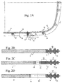
- FIG. 1 shows a plan view of a conventional carrier frame seal 1 with a support frame 4 and a sealing profile 6.
- the support frame 4 of the support frame seal 2 is further provided with recesses 10 and through holes through which screws can lead to the connection of two components to be sealed.
- a region 8 of a bypass of the recess 10 is highlighted with a circle.
- a line A is shown, which shows the section line along which the carrier frame seal 1 for representation in the Figure 1A is cut.
- Figure 1A shows the sectional view taken along the line A of FIG. 1 ,
- the carrier frame seal is cut in the region of a recess 10.
- the support frame surrounds the recess 10 on both sides thereof, outside with the gate 4 and inside with the bypass 12.
- a sealing profile 6 is vulcanized or molded.
- the sealing profile comprises a sealing region 18 with two parallel Sealing lips 16.
- FIG. 2A shows a plan view of a carrier frame seal 2 according to the invention, in which the recesses 10 for the fastening elements are open towards the side of the sealing profile 6, rings or ring elements 24 being inserted into the recesses.
- FIG. 2B is the cut of FIG. 2A englang the line B shown, with the support frame 4 and the sealing profile 6 with the, two sealing lips 16 comprehensive sealing area 18. Die FIG. 2B corresponds to the Figure 1A , without the passage opening.
- FIG. 2A Furthermore, a section line C is shown, which merely intersects the recess 10.
- the Figure 2C or the section C shows a flat gate through the provided with a ring 24 recess 10. Due to the flat section 5, the ring appears wider and the free space of the ring appears smaller.
- the sealing profile 6 includes there the same 18 with the same two side by side extending sealing lips 16, which extend at the same distance from each other.
- FIG. 2D clearly shows how narrow the bridge can be performed using the ring element.
- a conventional punched web which would achieve the same gain on the side of the sealing profile 6, could not be produced.
- such a bridge can not be produced by conventional and inexpensive punching methods, since its height in the punching direction is greater than or twice as large as its width.
- Such a thin web of the material of the support frame can be achieved only with other expensive manufacturing processes such as laser cutting, photoetching or spark erosion. It can also be seen that such a thin web of the material of the support frame 4 can not withstand the pressures in an injection molding machine, which is why it is to be feared that this will be damaged during molding of the sealing profile of the web.
- the ring in Figure 2C can be made of a stronger material than the material of the support frame, which is why the ring can withstand the forces acting on the injection molding of the sealing profile without deforming.
- a ring of stronger material can also accommodate bolting forces acting on the built-in seal in a region of less width.
- FIG. 3A illustrates a plan view of another embodiment according to the invention of a carrier frame seal 2 FIG. 3A the recesses 10 also extend to the edge. In the recesses rings or ring elements 24 are additionally inserted, which need not be prepared by punching.
- the FIGS. 3B to 3D each represent sectional views taken along lines B, C and D of FIG FIG. 3A in this FIG. 3A It can be seen that the sealing profile 6 is wider in the areas which are remote from the recesses, as directly to the recesses 10.
- the sealing profile is narrower in the region of the recesses and is brought together by two sealing lips 16 to a sealing lip 20 ,
- the section B or the FIG. 3B corresponds to the FIGS. 2A and 1A ,
- the sealing profile 6 comprises a sealing region 18 with two sealing lips 16 extending side by side.
- the section C or the FIG. 3C shows a flat gate through the provided with a ring 24 recess 10. Due to the flat section 5, the ring appears wider and the recess 10 appears smaller.
- the sealing profile 6 likewise comprises a sealing region 18 with two sealing lips 16 running side by side, which, however, are brought closer together.
- the section D or the Figure 3D shows a section straight through the center of the recess 10 and through the ring 24. By the straight cut the small radial thickness of the ring 24 can be seen, which is smaller than the axial extent of the ring 24.
- the sealing profile 6 also includes there a sealing area with only a single wider sealing lip 20, resulting from the converging sealing lips 16.
- This embodiment of the invention is based on the fact that the area of the critical screw connection opening or recess 10 is punched free and in this area an additional ring-shaped element or a ring 24 is inserted. It is also possible to use a plurality of annular elements in each case at several or all screwed openings. The annular elements 24 take over the function of Bolt opening bypass on the support plate 4, whereby the recess is completely closed inwardly to the screw 10. The actual support frame 4 does not bypass the recess 10 on the side to the elastomer sealing profile 6, since this area is formed in each case by the additional element or the additional ring 24.
- the actual support frame 4 always has an opening to the inside, in which then the ring is located, which takes on the task of the support frame at this point to surround the screw hole closed.
- the solution may be such that the ring 24 bears only minimally on the support frame side 4 up to an embodiment in which the ring element is still somewhat enclosed from both sides.
- the ring element is surrounded by the support frame more than half, and can then be particularly easily in the support frame positioned or pre-assembled with a press fit (or be clamped).
- the rings 24 could theoretically but also separately be used without direct connection to the support plate only in the tool, for example on pins, and be connected during the injection process with the support frame by elastomer.
- the annular elements 24 can be manufactured separately, which is why other manufacturing methods can be used as punching.
- the typical manufacturing limits of the stamping process can be circumvented.
- the manufacturing process is extrusion or machining. Likewise, drawing is possible as a production method. It is even possible to bend the ring elements of square wire, in use should point the seam in the direction of the support frame and not in the direction of the elastomer sealing profile.
- the ring elements can be manufactured cost-optimized with sufficient manufacturing accuracy. These elements can be manufactured with great accuracy. It is even intended to produce the ring elements by metal injection molding quickly and easily.
- a bypass with a square cross section is already at the limit of what can be produced inexpensively with a stamping method.
- Such a bypass requires a minimum width of 2 mm and would already have the disadvantages described above.
- Typical internal diameters are approximately 6.8 to 7mm for M6 screws, which are commonly used in such flange fittings.
- the production of a Ring element in the turning process with an inner diameter of about 7mm and a height of 2mm with a width of 2mm or even less no great challenge.
- annular elements can be made of a different material than the rest of the support frame. It is thus possible to produce an aluminum support frame 4 with annular elements 24 made of steel or brass in order to reduce the dimensions of the support frame seal even more with the same strength can.
- the annular elements can either be pre-assembled and connected as a unit to the support frame or separately inserted only in the injection mold. Depending on the combination of materials, pressing, gluing, welding are suitable for pre-assembly.
- overmolded carrier frame seals In the area of overmolded carrier frame seals, i. in seals in which a thin support plate is integrated in an elastomeric profile, there are already different embodiments with incorporated rings.
- the rings serve as spacers for sealing gap limitation.
- a thin carrier plate usually steel is used in which the function of spacers is effected by pressed or inserted rings.
- the support frame is in this case completely encapsulated and the rings are usually arranged centrally in the support frame.
- the ring or the ring member is used, which has the same axial dimension or thickness as the support frame.
- overmolded carrier frame seals can not be readily compared with carrier frame seals in which the sealing profile is molded onto only one end face.
- the present invention allows in one embodiment to achieve a minimal space and a smaller space than can be represented with all known solutions. It is now possible with the present invention to significantly reduce the dimensions of a carrier frame seal.
- the present invention permits the use of different combinations of materials to further optimize the support frame seal in terms of manufacturing cost, weight, dimensions, and packaging space.
- There are variants with different heights of the ring elements conceivable, but conventionally only ring elements are used whose dimensions correspond to the height of the support plate.
- the rings may have some overhang to be deformed to the optimum height when the tool is closed, and to securely seat the tool in place to avoid elastomer overflows.
- the properties of the carrier frame seal can be further influenced.
- the use of steel rings can increase the strength in the area of the screw eyes, and larger screw forces can be transmitted.
- the width of the ring by having the ring, for example, an oval outer shape and a round inner shape.
- the forces that are applied by the screws on the ring and especially on the sealing flange can be better distributed to prevent the ring can dig into the flange of an aluminum component.
Landscapes
- Engineering & Computer Science (AREA)
- General Engineering & Computer Science (AREA)
- Mechanical Engineering (AREA)
- Gasket Seals (AREA)
Claims (12)
- Joint à cadre support (2) à encombrement réduit, comprenant :- un cadre support (4) et- un profilé d'étanchéité (6) constitué d'un matériau élastomère, qui est vulcanisé en aboutement sur un côté frontal du cadre support (4) ,dans lequel le cadre support (4) est pourvu en outre de cavités pour des éléments de fixation,
caractérisé en ce que le cadre support (4) est interrompu au niveau d'au moins une cavité (10) sur le côté, sur lequel le profilé d'étanchéité est vulcanisé, et s'étend seulement sur le côté de la cavité (10), qui est en vis-à-vis du profilé d'étanchéité (6), dans lequel le cadre support (4) est pourvu sur au moins une cavité (10) d'une bague (24), qui est disposée dans au moins une cavité (10). - Joint à cadre support selon la revendication 1, caractérisé en ce que la bague (24) présente une épaisseur de paroi, qui est inférieure à une largeur d'un gradin, qui peut être découpé à l'emporte-pièce dans le cadre support, sans entamer le matériau du cadre support.
- Joint à cadre support selon la revendication 1, caractérisé en ce que un matériau, à partir duquel la bague (24) est fabriquée, présente une rigidité supérieure à un matériau, à partir duquel le cadre support (4) est fabriqué.
- Joint à cadre support selon une des revendications précédentes, dans lequel au moins une autre des cavités (10) est contournée par le profilé d'étanchéité (6), dans lequel le profilé d'étanchéité (6) a une largeur réduite au niveau d'au moins un contournement.
- Joint à cadre support selon la revendication 4, caractérisé en ce que le profilé d'étanchéité (610) présente au niveau d'au moins un contournement une lèvre d'étanchéité (20), et dans les zones à l'extérieur d'au moins un contournement deux lèvres d'étanchéité (16) qui s'étendent à côté l'une de l'autre.
- Joint à cadre support selon la revendication 5, caractérise en ce que une des lèvres d'étanchéité (20) est conçue plus large que chacune des deux lèvres d'étanchéité (16) s'étendant à côté l'une de l'autre.
- Joint à cadre support selon une des revendications précédentes, en dépendance de la revendication 1, caractérisé en ce que au moins une bague n'est pas ronde à l'extérieur.
- Joint à cadre support selon une des revendications précédentes, en dépendance de la revendication 1, caractérisé en ce que la bague n'est pas fermée.
- Joint à cadre support selon une des revendications précédentes, caractérisée en ce que le cadre support est découpé à l'emporte-pièce dans une tôle.
- Joint à cadre support selon une des revendications précédentes, caractérisé en ce que la bague (24) a une hauteur plus grande que le cadre support (4).
- Joint à cadre support selon une des revendications précédentes, caractérisé en ce que la bague (24) peut être reliée avec le cadre support (4) dans l'outil d'injection.
- Joint à cadre support selon une des revendications précédentes, caractérise en ce que la bague (24) peut être reliée avec le cadre support (4) bien avant le procédé d'injection.
Applications Claiming Priority (2)
| Application Number | Priority Date | Filing Date | Title |
|---|---|---|---|
| DE102012206626.8A DE102012206626B4 (de) | 2012-04-23 | 2012-04-23 | Trägerrahmendichtung mit verringertem Platzbedarf |
| PCT/EP2012/073694 WO2013159838A1 (fr) | 2012-04-23 | 2012-11-27 | Joint à cadre support à encombrement réduit |
Publications (2)
| Publication Number | Publication Date |
|---|---|
| EP2841823A1 EP2841823A1 (fr) | 2015-03-04 |
| EP2841823B1 true EP2841823B1 (fr) | 2016-06-08 |
Family
ID=47290947
Family Applications (1)
| Application Number | Title | Priority Date | Filing Date |
|---|---|---|---|
| EP12795402.2A Not-in-force EP2841823B1 (fr) | 2012-04-23 | 2012-11-27 | Joint à cadre support à encombrement réduit |
Country Status (3)
| Country | Link |
|---|---|
| EP (1) | EP2841823B1 (fr) |
| DE (1) | DE102012206626B4 (fr) |
| WO (1) | WO2013159838A1 (fr) |
Families Citing this family (2)
| Publication number | Priority date | Publication date | Assignee | Title |
|---|---|---|---|---|
| US9745046B2 (en) * | 2014-01-30 | 2017-08-29 | Ppg Industries Ohio, Inc. | Aircraft transparency with pressure seal and/or anti-static drain |
| DE102015112849A1 (de) * | 2015-08-05 | 2017-02-09 | Federal-Mogul Sealing Systems Gmbh | Trägerrahmendichtung mit asymmetrischen Dichtlippen |
Family Cites Families (5)
| Publication number | Priority date | Publication date | Assignee | Title |
|---|---|---|---|---|
| DE4213653C2 (de) * | 1992-04-25 | 1996-07-11 | Gloeckler Dichtungen Guenter H | Gummiformdichtung |
| US5492343A (en) * | 1994-03-04 | 1996-02-20 | Federal-Mogul Corporation | Gasket assembly |
| US5536023A (en) * | 1994-10-31 | 1996-07-16 | Indian Head Industries, Inc. | One piece gasket for complex oil pan configuration |
| US6553664B1 (en) * | 1999-12-17 | 2003-04-29 | Parker-Hannifin Corporation | Method of making a segmented gasket having a continuous seal member |
| DE102011011103A1 (de) * | 2011-02-12 | 2012-08-16 | Elringklinger Ag | Dichtung |
-
2012
- 2012-04-23 DE DE102012206626.8A patent/DE102012206626B4/de not_active Expired - Fee Related
- 2012-11-27 WO PCT/EP2012/073694 patent/WO2013159838A1/fr not_active Ceased
- 2012-11-27 EP EP12795402.2A patent/EP2841823B1/fr not_active Not-in-force
Non-Patent Citations (1)
| Title |
|---|
| None * |
Also Published As
| Publication number | Publication date |
|---|---|
| DE102012206626B4 (de) | 2015-05-28 |
| WO2013159838A1 (fr) | 2013-10-31 |
| DE102012206626A1 (de) | 2013-10-24 |
| EP2841823A1 (fr) | 2015-03-04 |
Similar Documents
| Publication | Publication Date | Title |
|---|---|---|
| EP0747614B1 (fr) | Joint de culasse métallique | |
| DE102008029236B3 (de) | Verbindungselement mit einer Schraube und einer daran unverlierbar angeordneten Hülse | |
| EP1391640B1 (fr) | Bague d'étanchéité | |
| EP2941798B1 (fr) | Boîtier de connecteur enfichable étanche au milieu ambiant | |
| EP1985897A1 (fr) | Joint plat métallique | |
| DE10353642A1 (de) | Funktionselement, Zusammenbauteil bestehend aus dem Funktionselement in Kombination mit einem Blechteil, Verfahren zur Herstellung des Zusammenbauteils sowie Verfahren zur Herstellung des Funktionselements | |
| DE102011015682A1 (de) | Kappe zur Verwendung in einer Fluiddruckvorrichtung und Befestigungsverfahren hierfür | |
| EP4286714B1 (fr) | Joint et procédé de fabrication d'un joint | |
| EP2841823B1 (fr) | Joint à cadre support à encombrement réduit | |
| WO2016008879A1 (fr) | Garniture d'étanchéité pressée avec corps en élastomère | |
| EP3025078B1 (fr) | Joint d'étanchéité à cadre support comportant une partie canal | |
| WO2006077121A1 (fr) | Pompe hydraulique de direction assistée | |
| EP1818240B1 (fr) | Plaque d'appui pour un mécanisme de direction | |
| EP2801725B1 (fr) | Dispositif comprenant au moins un canal pour l'acheminement d'un fluide de travail gazeux ou liquide | |
| EP4133915B1 (fr) | Couvercle | |
| EP2041460B1 (fr) | Joint d'etancheite a cadre support de poids reduit | |
| EP1259407B1 (fr) | Bloc hydraulique dote d'une piece rapportee fixee sur ledit bloc | |
| EP3564545B1 (fr) | Composant d'assemblage comprenant un composant et d'un élément doté d'une partie de tête et d'un col disposé sur un côté de la partie de tête ainsi que son procédé de fabrication | |
| EP4397869A2 (fr) | Élément fonctionnel, composant d'assemblage et procédé de fabrication d'un composant d'assemblage | |
| EP1734245B1 (fr) | Joint métallique multicouche | |
| EP3798580B1 (fr) | Procédé de fabrication d'un boitier de tête de mesure, couvercle et boitier de tête de mesure | |
| DE2265555C3 (de) | Winkelstück zur Flanschverbindung von im Querschnitt rechteckigen Klimatisierungskanälen o.dgl. | |
| DE10314693B4 (de) | Flachdichtung | |
| DE102016008501A1 (de) | Mikrofilter zum Filtern von Flüssigkeiten | |
| DE202009012558U1 (de) | Türfeststeller |
Legal Events
| Date | Code | Title | Description |
|---|---|---|---|
| PUAI | Public reference made under article 153(3) epc to a published international application that has entered the european phase |
Free format text: ORIGINAL CODE: 0009012 |
|
| 17P | Request for examination filed |
Effective date: 20140729 |
|
| AK | Designated contracting states |
Kind code of ref document: A1 Designated state(s): AL AT BE BG CH CY CZ DE DK EE ES FI FR GB GR HR HU IE IS IT LI LT LU LV MC MK MT NL NO PL PT RO RS SE SI SK SM TR |
|
| AX | Request for extension of the european patent |
Extension state: BA ME |
|
| DAX | Request for extension of the european patent (deleted) | ||
| GRAP | Despatch of communication of intention to grant a patent |
Free format text: ORIGINAL CODE: EPIDOSNIGR1 |
|
| INTG | Intention to grant announced |
Effective date: 20160128 |
|
| GRAS | Grant fee paid |
Free format text: ORIGINAL CODE: EPIDOSNIGR3 |
|
| GRAJ | Information related to disapproval of communication of intention to grant by the applicant or resumption of examination proceedings by the epo deleted |
Free format text: ORIGINAL CODE: EPIDOSDIGR1 |
|
| GRAP | Despatch of communication of intention to grant a patent |
Free format text: ORIGINAL CODE: EPIDOSNIGR1 |
|
| GRAS | Grant fee paid |
Free format text: ORIGINAL CODE: EPIDOSNIGR3 |
|
| INTC | Intention to grant announced (deleted) | ||
| GRAA | (expected) grant |
Free format text: ORIGINAL CODE: 0009210 |
|
| INTG | Intention to grant announced |
Effective date: 20160412 |
|
| AK | Designated contracting states |
Kind code of ref document: B1 Designated state(s): AL AT BE BG CH CY CZ DE DK EE ES FI FR GB GR HR HU IE IS IT LI LT LU LV MC MK MT NL NO PL PT RO RS SE SI SK SM TR |
|
| REG | Reference to a national code |
Ref country code: GB Ref legal event code: FG4D Free format text: NOT ENGLISH |
|
| REG | Reference to a national code |
Ref country code: CH Ref legal event code: EP |
|
| REG | Reference to a national code |
Ref country code: IE Ref legal event code: FG4D Free format text: LANGUAGE OF EP DOCUMENT: GERMAN |
|
| REG | Reference to a national code |
Ref country code: AT Ref legal event code: REF Ref document number: 805491 Country of ref document: AT Kind code of ref document: T Effective date: 20160715 |
|
| REG | Reference to a national code |
Ref country code: DE Ref legal event code: R096 Ref document number: 502012007384 Country of ref document: DE |
|
| REG | Reference to a national code |
Ref country code: LT Ref legal event code: MG4D |
|
| REG | Reference to a national code |
Ref country code: NL Ref legal event code: MP Effective date: 20160608 |
|
| REG | Reference to a national code |
Ref country code: FR Ref legal event code: PLFP Year of fee payment: 5 |
|
| PG25 | Lapsed in a contracting state [announced via postgrant information from national office to epo] |
Ref country code: NO Free format text: LAPSE BECAUSE OF FAILURE TO SUBMIT A TRANSLATION OF THE DESCRIPTION OR TO PAY THE FEE WITHIN THE PRESCRIBED TIME-LIMIT Effective date: 20160908 Ref country code: FI Free format text: LAPSE BECAUSE OF FAILURE TO SUBMIT A TRANSLATION OF THE DESCRIPTION OR TO PAY THE FEE WITHIN THE PRESCRIBED TIME-LIMIT Effective date: 20160608 Ref country code: LT Free format text: LAPSE BECAUSE OF FAILURE TO SUBMIT A TRANSLATION OF THE DESCRIPTION OR TO PAY THE FEE WITHIN THE PRESCRIBED TIME-LIMIT Effective date: 20160608 |
|
| PG25 | Lapsed in a contracting state [announced via postgrant information from national office to epo] |
Ref country code: SE Free format text: LAPSE BECAUSE OF FAILURE TO SUBMIT A TRANSLATION OF THE DESCRIPTION OR TO PAY THE FEE WITHIN THE PRESCRIBED TIME-LIMIT Effective date: 20160608 Ref country code: RS Free format text: LAPSE BECAUSE OF FAILURE TO SUBMIT A TRANSLATION OF THE DESCRIPTION OR TO PAY THE FEE WITHIN THE PRESCRIBED TIME-LIMIT Effective date: 20160608 Ref country code: NL Free format text: LAPSE BECAUSE OF FAILURE TO SUBMIT A TRANSLATION OF THE DESCRIPTION OR TO PAY THE FEE WITHIN THE PRESCRIBED TIME-LIMIT Effective date: 20160608 Ref country code: LV Free format text: LAPSE BECAUSE OF FAILURE TO SUBMIT A TRANSLATION OF THE DESCRIPTION OR TO PAY THE FEE WITHIN THE PRESCRIBED TIME-LIMIT Effective date: 20160608 Ref country code: GR Free format text: LAPSE BECAUSE OF FAILURE TO SUBMIT A TRANSLATION OF THE DESCRIPTION OR TO PAY THE FEE WITHIN THE PRESCRIBED TIME-LIMIT Effective date: 20160909 Ref country code: ES Free format text: LAPSE BECAUSE OF FAILURE TO SUBMIT A TRANSLATION OF THE DESCRIPTION OR TO PAY THE FEE WITHIN THE PRESCRIBED TIME-LIMIT Effective date: 20160608 Ref country code: HR Free format text: LAPSE BECAUSE OF FAILURE TO SUBMIT A TRANSLATION OF THE DESCRIPTION OR TO PAY THE FEE WITHIN THE PRESCRIBED TIME-LIMIT Effective date: 20160608 |
|
| PG25 | Lapsed in a contracting state [announced via postgrant information from national office to epo] |
Ref country code: SK Free format text: LAPSE BECAUSE OF FAILURE TO SUBMIT A TRANSLATION OF THE DESCRIPTION OR TO PAY THE FEE WITHIN THE PRESCRIBED TIME-LIMIT Effective date: 20160608 Ref country code: CZ Free format text: LAPSE BECAUSE OF FAILURE TO SUBMIT A TRANSLATION OF THE DESCRIPTION OR TO PAY THE FEE WITHIN THE PRESCRIBED TIME-LIMIT Effective date: 20160608 Ref country code: IS Free format text: LAPSE BECAUSE OF FAILURE TO SUBMIT A TRANSLATION OF THE DESCRIPTION OR TO PAY THE FEE WITHIN THE PRESCRIBED TIME-LIMIT Effective date: 20161008 Ref country code: RO Free format text: LAPSE BECAUSE OF FAILURE TO SUBMIT A TRANSLATION OF THE DESCRIPTION OR TO PAY THE FEE WITHIN THE PRESCRIBED TIME-LIMIT Effective date: 20160608 Ref country code: EE Free format text: LAPSE BECAUSE OF FAILURE TO SUBMIT A TRANSLATION OF THE DESCRIPTION OR TO PAY THE FEE WITHIN THE PRESCRIBED TIME-LIMIT Effective date: 20160608 |
|
| PG25 | Lapsed in a contracting state [announced via postgrant information from national office to epo] |
Ref country code: SM Free format text: LAPSE BECAUSE OF FAILURE TO SUBMIT A TRANSLATION OF THE DESCRIPTION OR TO PAY THE FEE WITHIN THE PRESCRIBED TIME-LIMIT Effective date: 20160608 Ref country code: PT Free format text: LAPSE BECAUSE OF FAILURE TO SUBMIT A TRANSLATION OF THE DESCRIPTION OR TO PAY THE FEE WITHIN THE PRESCRIBED TIME-LIMIT Effective date: 20161010 Ref country code: BE Free format text: LAPSE BECAUSE OF NON-PAYMENT OF DUE FEES Effective date: 20161130 Ref country code: PL Free format text: LAPSE BECAUSE OF FAILURE TO SUBMIT A TRANSLATION OF THE DESCRIPTION OR TO PAY THE FEE WITHIN THE PRESCRIBED TIME-LIMIT Effective date: 20160608 |
|
| REG | Reference to a national code |
Ref country code: DE Ref legal event code: R097 Ref document number: 502012007384 Country of ref document: DE |
|
| PLBE | No opposition filed within time limit |
Free format text: ORIGINAL CODE: 0009261 |
|
| STAA | Information on the status of an ep patent application or granted ep patent |
Free format text: STATUS: NO OPPOSITION FILED WITHIN TIME LIMIT |
|
| 26N | No opposition filed |
Effective date: 20170309 |
|
| PG25 | Lapsed in a contracting state [announced via postgrant information from national office to epo] |
Ref country code: DK Free format text: LAPSE BECAUSE OF FAILURE TO SUBMIT A TRANSLATION OF THE DESCRIPTION OR TO PAY THE FEE WITHIN THE PRESCRIBED TIME-LIMIT Effective date: 20160608 Ref country code: SI Free format text: LAPSE BECAUSE OF FAILURE TO SUBMIT A TRANSLATION OF THE DESCRIPTION OR TO PAY THE FEE WITHIN THE PRESCRIBED TIME-LIMIT Effective date: 20160608 |
|
| REG | Reference to a national code |
Ref country code: CH Ref legal event code: PL |
|
| GBPC | Gb: european patent ceased through non-payment of renewal fee |
Effective date: 20161127 |
|
| PG25 | Lapsed in a contracting state [announced via postgrant information from national office to epo] |
Ref country code: LI Free format text: LAPSE BECAUSE OF NON-PAYMENT OF DUE FEES Effective date: 20161130 Ref country code: CH Free format text: LAPSE BECAUSE OF NON-PAYMENT OF DUE FEES Effective date: 20161130 |
|
| REG | Reference to a national code |
Ref country code: IE Ref legal event code: MM4A |
|
| PG25 | Lapsed in a contracting state [announced via postgrant information from national office to epo] |
Ref country code: LU Free format text: LAPSE BECAUSE OF NON-PAYMENT OF DUE FEES Effective date: 20161130 |
|
| REG | Reference to a national code |
Ref country code: FR Ref legal event code: PLFP Year of fee payment: 6 |
|
| PG25 | Lapsed in a contracting state [announced via postgrant information from national office to epo] |
Ref country code: GB Free format text: LAPSE BECAUSE OF NON-PAYMENT OF DUE FEES Effective date: 20161127 Ref country code: IE Free format text: LAPSE BECAUSE OF NON-PAYMENT OF DUE FEES Effective date: 20161127 |
|
| REG | Reference to a national code |
Ref country code: BE Ref legal event code: MM Effective date: 20161130 |
|
| PG25 | Lapsed in a contracting state [announced via postgrant information from national office to epo] |
Ref country code: HU Free format text: LAPSE BECAUSE OF FAILURE TO SUBMIT A TRANSLATION OF THE DESCRIPTION OR TO PAY THE FEE WITHIN THE PRESCRIBED TIME-LIMIT; INVALID AB INITIO Effective date: 20121127 |
|
| PG25 | Lapsed in a contracting state [announced via postgrant information from national office to epo] |
Ref country code: MK Free format text: LAPSE BECAUSE OF FAILURE TO SUBMIT A TRANSLATION OF THE DESCRIPTION OR TO PAY THE FEE WITHIN THE PRESCRIBED TIME-LIMIT Effective date: 20160608 Ref country code: CY Free format text: LAPSE BECAUSE OF FAILURE TO SUBMIT A TRANSLATION OF THE DESCRIPTION OR TO PAY THE FEE WITHIN THE PRESCRIBED TIME-LIMIT Effective date: 20160608 Ref country code: MC Free format text: LAPSE BECAUSE OF FAILURE TO SUBMIT A TRANSLATION OF THE DESCRIPTION OR TO PAY THE FEE WITHIN THE PRESCRIBED TIME-LIMIT Effective date: 20160608 |
|
| PG25 | Lapsed in a contracting state [announced via postgrant information from national office to epo] |
Ref country code: BG Free format text: LAPSE BECAUSE OF FAILURE TO SUBMIT A TRANSLATION OF THE DESCRIPTION OR TO PAY THE FEE WITHIN THE PRESCRIBED TIME-LIMIT Effective date: 20160608 |
|
| PG25 | Lapsed in a contracting state [announced via postgrant information from national office to epo] |
Ref country code: MT Free format text: LAPSE BECAUSE OF FAILURE TO SUBMIT A TRANSLATION OF THE DESCRIPTION OR TO PAY THE FEE WITHIN THE PRESCRIBED TIME-LIMIT Effective date: 20160608 |
|
| REG | Reference to a national code |
Ref country code: FR Ref legal event code: PLFP Year of fee payment: 7 |
|
| PG25 | Lapsed in a contracting state [announced via postgrant information from national office to epo] |
Ref country code: AL Free format text: LAPSE BECAUSE OF FAILURE TO SUBMIT A TRANSLATION OF THE DESCRIPTION OR TO PAY THE FEE WITHIN THE PRESCRIBED TIME-LIMIT Effective date: 20160608 Ref country code: TR Free format text: LAPSE BECAUSE OF FAILURE TO SUBMIT A TRANSLATION OF THE DESCRIPTION OR TO PAY THE FEE WITHIN THE PRESCRIBED TIME-LIMIT Effective date: 20160608 |
|
| REG | Reference to a national code |
Ref country code: AT Ref legal event code: MM01 Ref document number: 805491 Country of ref document: AT Kind code of ref document: T Effective date: 20171127 |
|
| PG25 | Lapsed in a contracting state [announced via postgrant information from national office to epo] |
Ref country code: AT Free format text: LAPSE BECAUSE OF NON-PAYMENT OF DUE FEES Effective date: 20171127 |
|
| PGFP | Annual fee paid to national office [announced via postgrant information from national office to epo] |
Ref country code: DE Payment date: 20191017 Year of fee payment: 8 |
|
| PGFP | Annual fee paid to national office [announced via postgrant information from national office to epo] |
Ref country code: FR Payment date: 20191029 Year of fee payment: 8 Ref country code: IT Payment date: 20191120 Year of fee payment: 8 |
|
| REG | Reference to a national code |
Ref country code: DE Ref legal event code: R119 Ref document number: 502012007384 Country of ref document: DE |
|
| PG25 | Lapsed in a contracting state [announced via postgrant information from national office to epo] |
Ref country code: FR Free format text: LAPSE BECAUSE OF NON-PAYMENT OF DUE FEES Effective date: 20201130 Ref country code: IT Free format text: LAPSE BECAUSE OF NON-PAYMENT OF DUE FEES Effective date: 20201127 |
|
| PG25 | Lapsed in a contracting state [announced via postgrant information from national office to epo] |
Ref country code: DE Free format text: LAPSE BECAUSE OF NON-PAYMENT OF DUE FEES Effective date: 20210601 |