EP4397869A2 - Élément fonctionnel, composant d'assemblage et procédé de fabrication d'un composant d'assemblage - Google Patents
Élément fonctionnel, composant d'assemblage et procédé de fabrication d'un composant d'assemblage Download PDFInfo
- Publication number
- EP4397869A2 EP4397869A2 EP24178338.0A EP24178338A EP4397869A2 EP 4397869 A2 EP4397869 A2 EP 4397869A2 EP 24178338 A EP24178338 A EP 24178338A EP 4397869 A2 EP4397869 A2 EP 4397869A2
- Authority
- EP
- European Patent Office
- Prior art keywords
- workpiece
- functional element
- flank
- contact surface
- axial direction
- Prior art date
- Legal status (The legal status is an assumption and is not a legal conclusion. Google has not performed a legal analysis and makes no representation as to the accuracy of the status listed.)
- Granted
Links
Images



Classifications
-
- F—MECHANICAL ENGINEERING; LIGHTING; HEATING; WEAPONS; BLASTING
- F16—ENGINEERING ELEMENTS AND UNITS; GENERAL MEASURES FOR PRODUCING AND MAINTAINING EFFECTIVE FUNCTIONING OF MACHINES OR INSTALLATIONS; THERMAL INSULATION IN GENERAL
- F16B—DEVICES FOR FASTENING OR SECURING CONSTRUCTIONAL ELEMENTS OR MACHINE PARTS TOGETHER, e.g. NAILS, BOLTS, CIRCLIPS, CLAMPS, CLIPS OR WEDGES; JOINTS OR JOINTING
- F16B19/00—Bolts without screw-thread; Pins, including deformable elements; Rivets
- F16B19/04—Rivets; Spigots or the like fastened by riveting
- F16B19/06—Solid rivets made in one piece
-
- F—MECHANICAL ENGINEERING; LIGHTING; HEATING; WEAPONS; BLASTING
- F16—ENGINEERING ELEMENTS AND UNITS; GENERAL MEASURES FOR PRODUCING AND MAINTAINING EFFECTIVE FUNCTIONING OF MACHINES OR INSTALLATIONS; THERMAL INSULATION IN GENERAL
- F16B—DEVICES FOR FASTENING OR SECURING CONSTRUCTIONAL ELEMENTS OR MACHINE PARTS TOGETHER, e.g. NAILS, BOLTS, CIRCLIPS, CLAMPS, CLIPS OR WEDGES; JOINTS OR JOINTING
- F16B35/00—Screw-bolts; Stay-bolts; Screw-threaded studs; Screws; Set screws
- F16B35/04—Screw-bolts; Stay-bolts; Screw-threaded studs; Screws; Set screws with specially-shaped head or shaft in order to fix the bolt on or in an object
- F16B35/041—Specially-shaped shafts
- F16B35/048—Specially-shaped necks
-
- F—MECHANICAL ENGINEERING; LIGHTING; HEATING; WEAPONS; BLASTING
- F16—ENGINEERING ELEMENTS AND UNITS; GENERAL MEASURES FOR PRODUCING AND MAINTAINING EFFECTIVE FUNCTIONING OF MACHINES OR INSTALLATIONS; THERMAL INSULATION IN GENERAL
- F16B—DEVICES FOR FASTENING OR SECURING CONSTRUCTIONAL ELEMENTS OR MACHINE PARTS TOGETHER, e.g. NAILS, BOLTS, CIRCLIPS, CLAMPS, CLIPS OR WEDGES; JOINTS OR JOINTING
- F16B19/00—Bolts without screw-thread; Pins, including deformable elements; Rivets
- F16B19/008—Bolts without screw-thread; Pins, including deformable elements; Rivets with sealing means
-
- B—PERFORMING OPERATIONS; TRANSPORTING
- B23—MACHINE TOOLS; METAL-WORKING NOT OTHERWISE PROVIDED FOR
- B23P—METAL-WORKING NOT OTHERWISE PROVIDED FOR; COMBINED OPERATIONS; UNIVERSAL MACHINE TOOLS
- B23P19/00—Machines for simply fitting together or separating metal parts or objects, or metal and non-metal parts, whether or not involving some deformation; Tools or devices therefor so far as not provided for in other classes
- B23P19/02—Machines for simply fitting together or separating metal parts or objects, or metal and non-metal parts, whether or not involving some deformation; Tools or devices therefor so far as not provided for in other classes for connecting objects by press fit or for detaching same
-
- F—MECHANICAL ENGINEERING; LIGHTING; HEATING; WEAPONS; BLASTING
- F16—ENGINEERING ELEMENTS AND UNITS; GENERAL MEASURES FOR PRODUCING AND MAINTAINING EFFECTIVE FUNCTIONING OF MACHINES OR INSTALLATIONS; THERMAL INSULATION IN GENERAL
- F16B—DEVICES FOR FASTENING OR SECURING CONSTRUCTIONAL ELEMENTS OR MACHINE PARTS TOGETHER, e.g. NAILS, BOLTS, CIRCLIPS, CLAMPS, CLIPS OR WEDGES; JOINTS OR JOINTING
- F16B33/00—Features common to bolt and nut
- F16B33/004—Sealing; Insulation
-
- F—MECHANICAL ENGINEERING; LIGHTING; HEATING; WEAPONS; BLASTING
- F16—ENGINEERING ELEMENTS AND UNITS; GENERAL MEASURES FOR PRODUCING AND MAINTAINING EFFECTIVE FUNCTIONING OF MACHINES OR INSTALLATIONS; THERMAL INSULATION IN GENERAL
- F16B—DEVICES FOR FASTENING OR SECURING CONSTRUCTIONAL ELEMENTS OR MACHINE PARTS TOGETHER, e.g. NAILS, BOLTS, CIRCLIPS, CLAMPS, CLIPS OR WEDGES; JOINTS OR JOINTING
- F16B35/00—Screw-bolts; Stay-bolts; Screw-threaded studs; Screws; Set screws
-
- F—MECHANICAL ENGINEERING; LIGHTING; HEATING; WEAPONS; BLASTING
- F16—ENGINEERING ELEMENTS AND UNITS; GENERAL MEASURES FOR PRODUCING AND MAINTAINING EFFECTIVE FUNCTIONING OF MACHINES OR INSTALLATIONS; THERMAL INSULATION IN GENERAL
- F16B—DEVICES FOR FASTENING OR SECURING CONSTRUCTIONAL ELEMENTS OR MACHINE PARTS TOGETHER, e.g. NAILS, BOLTS, CIRCLIPS, CLAMPS, CLIPS OR WEDGES; JOINTS OR JOINTING
- F16B37/00—Nuts or like thread-engaging members
- F16B37/04—Devices for fastening nuts to surfaces, e.g. sheets, plates
- F16B37/06—Devices for fastening nuts to surfaces, e.g. sheets, plates by means of welding or riveting
- F16B37/062—Devices for fastening nuts to surfaces, e.g. sheets, plates by means of welding or riveting by means of riveting
- F16B37/068—Devices for fastening nuts to surfaces, e.g. sheets, plates by means of welding or riveting by means of riveting by deforming the material of the support, e.g. the sheet or plate
-
- F—MECHANICAL ENGINEERING; LIGHTING; HEATING; WEAPONS; BLASTING
- F16—ENGINEERING ELEMENTS AND UNITS; GENERAL MEASURES FOR PRODUCING AND MAINTAINING EFFECTIVE FUNCTIONING OF MACHINES OR INSTALLATIONS; THERMAL INSULATION IN GENERAL
- F16B—DEVICES FOR FASTENING OR SECURING CONSTRUCTIONAL ELEMENTS OR MACHINE PARTS TOGETHER, e.g. NAILS, BOLTS, CIRCLIPS, CLAMPS, CLIPS OR WEDGES; JOINTS OR JOINTING
- F16B39/00—Locking of screws, bolts or nuts
- F16B39/22—Locking of screws, bolts or nuts in which the locking takes place during screwing down or tightening
- F16B39/28—Locking of screws, bolts or nuts in which the locking takes place during screwing down or tightening by special members on, or shape of, the nut or bolt
- F16B39/282—Locking by means of special shape of work-engaging surfaces, e.g. notched or toothed nuts
Definitions
- the invention relates to a functional element for pressing into a workpiece, in particular into a sheet metal part, an assembly part which has a workpiece with a hole, in particular a sheet metal part, and such a functional element, and a method for producing the assembly part.
- Such elements usually have a functional section, which in turn is used to attach other components. They are widely used in automotive engineering, among other places.
- Functional elements are known in various designs. On the one hand, there are, for example, rivet elements that have a rivet section that is deformed when attached to a sheet metal part to form a rivet flange and, with the head part, to form an annular receptacle for the edge of a hole in the sheet metal part. With such rivet elements, the functional element is deformed when attached to the sheet metal part.
- Press-in elements are also known in which the element itself is not intentionally deformed when attached to a sheet metal part, but rather the sheet metal material itself is deformed in order to bring it into engagement with undercuts of the respective press-in element.
- a coating is usually applied to parts of the functional elements that come into contact with the workpiece.
- the application takes place in a separate manufacturing step, which leads to increased effort and therefore higher costs and time requirements.
- this solution causes increased environmental pollution due to the coating.
- a functional element according to a first aspect of the invention is suitable for being pressed into a workpiece, in particular into a sheet metal part, and comprises a functional section and a fastening section with a stop surface for introducing a press-in force into the functional element, a workpiece contact surface opposite the stop surface, which can be brought into contact with the workpiece and which is in particular designed like a flange, and a sealing region located in an axial direction and/or a radial direction of the functional element between the workpiece contact surface and the functional section for receiving displaced material of the workpiece.
- the sealing region forms a contact surface for the displaced material in order to seal a connection between the functional element and the workpiece, wherein the contact surface has a first partial surface which runs obliquely to the axial direction of the functional element and which converges when viewed in a press-in direction of the functional element, and a second partial surface which adjoins the first partial surface, runs obliquely to the axial direction of the functional element and diverges when viewed in the pressing direction of the functional element.
- the functional element can be a press-in bolt, in particular a press-in bolt with a flange, or a nut element, which are preferably used for ductile sheet metal parts in order to facilitate the press-in process.
- the shaft preferably has an external thread and forms the functional section.
- the nut element on the other hand, preferably has an internal thread, which forms the functional section. Instead of the thread, other features can also be provided, which are suitable, for example, for fastening another component or for providing another functionality.
- the functional section can also be designed in sections or completely as a smooth pin or as a smooth hole.
- the fastening section is the section of the functional element with which the functional element is fastened to the workpiece.
- the press-in direction refers to the direction in which the functional element is pressed into the sheet metal part.
- the press-in direction can in particular run in the direction of the axial direction of the functional element, preferably from the stop surface in the direction of the workpiece contact surface.
- the stop surface and/or the workpiece contact surface preferably extend approximately perpendicular to the press-in direction.
- the first partial surface is inclined by approximately 20° to approximately 40°, in particular approximately 30°, to the axial direction.
- the first partial surface has a relatively small inclination to the axial direction, so that the material of the workpiece can be pressed tightly against the first partial surface.
- the second partial surface is inclined by approximately 50° to approximately 70°, in particular approximately 60°, to the axial direction.
- the second partial surface is comparatively strongly inclined to the axial direction, whereby an undercut can be formed by means of the second partial surface in addition to the sealing function.
- the functional element is thus securely held in or on the workpiece.
- first partial surface and the second partial surface can run approximately at right angles to each other.
- the first partial surface is connected to the second partial surface by a rounded transition region in order to avoid cavities at the transition from the first partial surface to the second partial surface and resulting leaks.
- a radius of curvature of the transition region can be in particular in the range of about 0.5 mm or less, in particular about 0.25 mm to 0.35 mm.
- a functional element according to a further aspect of the invention is suitable for pressing into a workpiece, in particular into a sheet metal part, and comprises a functional section and a fastening section with a stop surface for introducing a pressing force into the functional element, a workpiece contact surface opposite the stop surface, which can be brought into contact with the workpiece and is in particular designed like a flange, and a sealing region located in an axial direction and/or a radial direction of the functional element between the workpiece contact surface and the functional section for receiving displaced material from the workpiece.
- the sealing region forms a contact surface for the displaced material in order to seal a connection between the functional element and the workpiece, wherein the fastening section has a projection which delimits the sealing region in the axial direction and which has a first flank facing the sealing region and a second flank facing away from the sealing region, which run obliquely and with different degrees of inclination to the axial direction.
- the projection can be provided in particular in the circumferential direction on the shaft of a functional element designed as a bolt element and can also be referred to as a lip.
- the projection preferably protrudes radially outwards and comprises at least the first flank and the second flank.
- the first flank can form at least part of the contact surface, in particular the second partial surface.
- a thickness of the workpiece can be smaller or substantially equal to an axial extension of the sealing region, at least in the region of the hole.
- the functional element is self-punching, so that pre-punching of the workpiece is unnecessary.
- the workpiece rests on a support that includes a suitable die during the process.
- the press-in force introduced then also serves to displace the material.
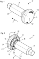
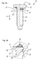
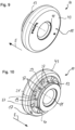
- a functional element 10 designed as a press-in bolt with flange is visible, and Figs. 9 and 10 show a functional element 10 designed as a nut element, which has a functional section 11 and a fastening section 13.
- the fastening section 13 is the section of the functional element 10 with which the functional element 10 is fastened to a workpiece 50 described in more detail later.
- the functional elements 10 each have a head 43.
- the functional element 10 designed as a press-in bolt according to Fig. 1 and 2 also has a shaft 41 on which a thread 45 (external thread) is formed. An internal thread 45 (see Fig. 11a ) intended.
- the shaft 41 of element 10 of the Fig. 1 and 2 extends from the side facing away from the stop surface 15. However, it is also possible to arrange the shaft on the stop surface 15 (this would then be ring-shaped in the case of a shaft with a round cross-section). If the design of the fastening section 13 remains otherwise unchanged, the sealing area 19 is located in an axial view then also between the workpiece contact surface 17 and the functional section 11.
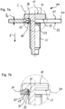
- the design of the contact surface 21 is clearly shown in Fig. 3a to Fig. 5 shown.
- This comprises a conical first partial surface 23, which runs obliquely to the axial direction of the functional element 10 and converges when viewed in a press-in direction E of the functional element 10, and a conical second partial surface 25, which lies between the first partial surface 23 and the functional section 11 when viewed in the press-in direction E and which adjoins the first partial surface 23 by means of a rounded transition region 27, also runs obliquely to the axial direction of the functional element 10 and diverges when viewed in the press-in direction E of the functional element 10.
- the first partial surface 23 can be inclined by approximately 20° to approximately 40°, in particular approximately 30°, to the axial direction
- the second partial surface 25 can be inclined by approximately 50° to approximately 70°, in particular approximately 60°, to the axial direction.
- the two partial surfaces 23, 25 can be approximately perpendicular to each other.
- the angle between the partial surfaces 23, 25 can be as in Fig.5 shown, can also be larger than 90°, up to about 135°.
- the contact surface 21 of the functional element 10 designed as a nut element also comprises a first partial surface 23 and a conical second partial surface 25, which adjoins the first partial surface 23 by means of a rounded transition region 27, runs obliquely to the axial direction of the functional element 10 and diverges when viewed in the pressing direction E of the functional element 10.
- the first partial surface 23 runs approximately parallel to the pressing direction E, but the functional element 10 can also be designed such that the first partial surface 23 runs obliquely to the axial direction and converges when viewed in the pressing direction E, as in Fig. 11b indicated by dashed lines.
- the contact surface 21, namely the first partial surface 23, extends into a (ring) recess 39 of the elements 10, which is made in the head 43, according to the Fig. 1 to 8b and there merges into the workpiece contact surface 17.
- a (ring) recess 39 of the elements 10 which is made in the head 43, according to the Fig. 1 to 8b and there merges into the workpiece contact surface 17.
- several radially extending ribs are formed as anti-twist features 37.
- the recess 39 is also directed opposite to the pressing direction E of the functional element 10, so that material of the workpiece 50 can be at least partially displaced when pressed into the recess 39 and in the process clings to the first partial surface 23.
- Element 10 according to the Fig. 9 to 11b does not have this recess 39. Instead, a wedge-shaped elevation 40 is provided, which slopes radially inwards and merges into the first partial surface 23 via a rounded transition section 28.
- the surface 23 has anti-twist features 37 in the form of axial ribs evenly distributed in the circumferential direction.
- the elevation also preferably has anti-twist features 37, here for example radial grooves evenly distributed in the circumferential direction.
- the recess 39 and the elevation 40 described above can be combined if required - also in a modified form - and implemented in both a nut element and a bolt element.
- the fastening section 13 also comprises a projection 29 which extends radially outwards and delimits the sealing area 19 in the axial direction.
- the projection 29 has a first flank 31 facing the sealing area 19, on which the second partial surface 25 of the contact surface 21 is formed. and a second flank 33 facing away from the sealing area 19.
- the projection 29 of the functional element 10 designed as a press-in bolt also has, unlike the nut element, an optional connecting section 35 which connects the two flanks 31, 33 to one another.
- the diameter of the projection 29 varies along its axial extent and, viewed in the press-in direction E, increases in the area of the first flank 31, remains constant in the area of the connecting section 35 and decreases in the area of the second flank 33.
- the flanks 31, 33 accordingly run obliquely to the axial direction of the functional element 10.
- the first flank 31 can be inclined more strongly to the axial direction than the second flank 33. This results on the one hand in a particularly effective design of the contact surface 21 and an effective undercut by the projection 29. On the other hand, a comparatively small adjustment or inclination of the second flank 33 facilitates the introduction of the projection 29 into the forming hole.
- the projection 29 can be designed approximately symmetrically, resulting in an equal inclination of the flanks 31, 33 to the axial direction (see, for example, Fig. 3b ), or the first flank 31 may be less inclined to the axial direction than the second flank 33, as for example in Fig.5 shown.
- the first flank 31 can advantageously be inclined by approximately 50° to approximately 70°, in particular approximately 60°, to the axial direction
- the second flank 33 can be inclined by approximately 15° to approximately 35°, in particular approximately 25°, to the axial direction.
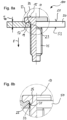
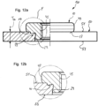
- Fig. 6a to Fig. 8b and Fig. 12a and 12b which each show an assembly part 100 according to the present invention.
- the workpiece 50 is designed as a sheet metal part with preferably ductile properties.
- the workpiece 50 has a surface 51 against which the workpiece contact surface 17 of the functional element 10 rests, and a surface 53 on an opposite side of the workpiece 50.
- the workpiece 50 shown in Figs. 8a and 8b has increasing thicknesses T 50 in order to illustrate that the inventive concept can be used for workpieces with a wide variety of properties.
- a functional element 10 according to the invention and a workpiece 50, in particular a sheet metal part in which a shaped hole is made, are provided.
- the functional element 10 is then introduced into the shaped hole so that the workpiece contact surface 17 faces the surface 51.
- a pressing force is introduced into the stop surface 15, which causes the workpiece contact surface 17 to be brought into contact with the workpiece 50.
- This pressing force can be used to force material of the workpiece 50 into the sealing area 19 and to press it against the contact surface 21.
- a die (not shown in the figures) can be provided on the surface 53 facing away from the workpiece contact surface 17. The pressing force presses a stamp of the die into the surface 53, whereby an annular groove 55 is formed in an area of the workpiece 50 adjacent to the hole. Pressing the stamp of the die into the workpiece 50 in an area adjacent to the hole thus displaces material from the workpiece 50, which flows into the sealing area 19 and thereby clings to the contact surface 21.
- the displacement of the material is not effected by a die with a punch, but the surface 53 of the workpiece 50 rests on a support surface that is essentially flat in the area around the hole.
- the displacement of the material is effected here by partially pressing the head 43 into the surface 51. The material cannot escape downwards due to the flat support surface and is therefore forced into the sealing area 19 until it lies flat and thus tightly against the first partial surface 23.
Landscapes
- Engineering & Computer Science (AREA)
- General Engineering & Computer Science (AREA)
- Mechanical Engineering (AREA)
- Connection Of Plates (AREA)
- Gasket Seals (AREA)
- Lining Or Joining Of Plastics Or The Like (AREA)
- Automatic Assembly (AREA)
- Exhaust Gas After Treatment (AREA)
Applications Claiming Priority (2)
| Application Number | Priority Date | Filing Date | Title |
|---|---|---|---|
| DE102021100073.4A DE102021100073A1 (de) | 2021-01-05 | 2021-01-05 | Funktionselement, Zusammenbauteil und Verfahren zum Herstellen eines Zusammenbauteils |
| EP21215812.5A EP4023894B1 (fr) | 2021-01-05 | 2021-12-20 | Élément fonctionnel, composant d'assemblage et procédé de fabrication d'un composant d'assemblage |
Related Parent Applications (2)
| Application Number | Title | Priority Date | Filing Date |
|---|---|---|---|
| EP21215812.5A Division EP4023894B1 (fr) | 2021-01-05 | 2021-12-20 | Élément fonctionnel, composant d'assemblage et procédé de fabrication d'un composant d'assemblage |
| EP21215812.5A Division-Into EP4023894B1 (fr) | 2021-01-05 | 2021-12-20 | Élément fonctionnel, composant d'assemblage et procédé de fabrication d'un composant d'assemblage |
Publications (3)
| Publication Number | Publication Date |
|---|---|
| EP4397869A2 true EP4397869A2 (fr) | 2024-07-10 |
| EP4397869A3 EP4397869A3 (fr) | 2024-09-04 |
| EP4397869B1 EP4397869B1 (fr) | 2026-02-25 |
Family
ID=79230584
Family Applications (2)
| Application Number | Title | Priority Date | Filing Date |
|---|---|---|---|
| EP24178338.0A Active EP4397869B1 (fr) | 2021-01-05 | 2021-12-20 | Élément fonctionnel, composant d'assemblage et procédé de fabrication d'un composant d'assemblage |
| EP21215812.5A Active EP4023894B1 (fr) | 2021-01-05 | 2021-12-20 | Élément fonctionnel, composant d'assemblage et procédé de fabrication d'un composant d'assemblage |
Family Applications After (1)
| Application Number | Title | Priority Date | Filing Date |
|---|---|---|---|
| EP21215812.5A Active EP4023894B1 (fr) | 2021-01-05 | 2021-12-20 | Élément fonctionnel, composant d'assemblage et procédé de fabrication d'un composant d'assemblage |
Country Status (8)
| Country | Link |
|---|---|
| US (2) | US20220235805A1 (fr) |
| EP (2) | EP4397869B1 (fr) |
| KR (1) | KR20220099105A (fr) |
| CN (2) | CN118654050A (fr) |
| DE (1) | DE102021100073A1 (fr) |
| ES (1) | ES3033774T3 (fr) |
| PL (1) | PL4023894T3 (fr) |
| TW (1) | TW202233968A (fr) |
Families Citing this family (1)
| Publication number | Priority date | Publication date | Assignee | Title |
|---|---|---|---|---|
| EP4617512B1 (fr) | 2024-03-15 | 2026-05-06 | Böllhoff Verbindungstechnik GmbH | Manchon de fixation métallique auto-poinçonneur, premier composant doté du manchon de fixation, structure de connexion comprenant le premier composant et procédé de pose du manchon de fixation |
Family Cites Families (25)
| Publication number | Priority date | Publication date | Assignee | Title |
|---|---|---|---|---|
| US3276499A (en) * | 1963-12-30 | 1966-10-04 | Republic Steel Corp | Flush-driven self-piercing and clinching nut and method of securing to a member |
| US4380414A (en) * | 1979-04-04 | 1983-04-19 | The Lamson & Sessions Co. | Fastener |
| US4820076A (en) * | 1984-11-08 | 1989-04-11 | Allied-Signal Inc. | Staked stud torque retention ribs |
| FR2688835B1 (fr) * | 1992-03-20 | 1995-09-15 | Thiant Boulonnerie | Perfectionnement a un ecrou autosertisseur et autopoinconneur. |
| WO1994001688A1 (fr) * | 1992-07-07 | 1994-01-20 | Richard Bergner Gmbh & Co. | Element d'insertion utilise comme element d'assemblage pour assemblage resistant a l'ejection et ne devant pas tourner |
| WO1995027147A1 (fr) * | 1994-04-04 | 1995-10-12 | Textron Inc. | Element de fixation autoassujetti a gorge inferieure de blocage |
| US5513933A (en) * | 1994-04-04 | 1996-05-07 | Textron Inc. | Staked fastener with undercut |
| US5743691A (en) * | 1997-02-03 | 1998-04-28 | Textron Inc. | Clinch-type fastener member |
| DE20012097U1 (de) * | 2000-07-12 | 2000-12-28 | Textron Verbindungstechnik GmbH & Co. oHG, 56567 Neuwied | Verdreh- und auspreßsicher in ein Blech einpreßbares Befestigungselement |
| DE202004000463U1 (de) * | 2004-01-13 | 2004-08-19 | Textron Verbindungstechnik Gmbh & Co. Ohg | Verdreh- und auspresssicher in ein Blech einpressbarer Bolzen |
| DE102004062391A1 (de) * | 2004-12-23 | 2006-07-13 | Profil-Verbindungstechnik Gmbh & Co. Kg | Ein durch Nieten an ein Blechteil anbringbares Element sowie Zusammenbauteil und Verfahren zur Erzeugung des Zusammenbauteils |
| US20060222473A1 (en) * | 2005-04-04 | 2006-10-05 | Ladouceur Harold A | Self-attaching nut and sealed nut and panel assembly |
| DE202006008721U1 (de) * | 2006-06-01 | 2007-10-11 | Profil Verbindungstechnik Gmbh & Co. Kg | Nietmutter und Kombination einer Nietmutter mit einem Blechteil |
| DE102007004118A1 (de) * | 2006-11-17 | 2008-05-29 | Nedschroef Plettenberg Gmbh | Stanzmutter |
| DE102011009012A1 (de) * | 2011-01-20 | 2012-07-26 | Profil Verbindungstechnik Gmbh & Co. Kg | Funktionselement in Form eines Einpresselements |
| DE102011108224A1 (de) * | 2011-07-21 | 2013-01-24 | Profil Verbindungstechnik Gmbh & Co. Kg | Funktionselement mit Verdrehsicherungsmerkmalen sowie Zusammenbauteil bestehend aus dem Funktionselement und einem Blechteil |
| JP2013122283A (ja) * | 2011-12-12 | 2013-06-20 | Pias Hanbai Kk | ピアスナット |
| DE102012001086A1 (de) * | 2012-01-20 | 2013-07-25 | Profil Verbindungstechnik Gmbh & Co. Kg | Bolzenelement und Verfahren zur Anbringung eines Bolzenelements an einem Bauteil aus einem Verbundwerkstoff |
| EP2644911A3 (fr) * | 2012-03-27 | 2016-08-17 | Profil Verbindungstechnik GmbH & Co. KG | Elément de fonction sous la forme d'un élément de compression |
| EP2867548B1 (fr) * | 2012-06-29 | 2021-10-13 | Infastech Intellectual Properties Pte. Ltd. | Attache autobloqueuse |
| DE102013101068A1 (de) | 2013-02-01 | 2014-08-07 | Ejot Tezmak Baglanti Elemanlari Teknolojileri San. Ve Tic. A.S. | Einpressbolzen |
| CN203374612U (zh) * | 2013-07-25 | 2014-01-01 | 超捷紧固系统(上海)股份有限公司 | 金属薄板钣金件用的压铆连接紧固件 |
| CN103382957A (zh) * | 2013-07-25 | 2013-11-06 | 超捷紧固系统(上海)股份有限公司 | 金属薄板钣金件用的压铆连接紧固件 |
| DE102016204619B4 (de) * | 2016-03-21 | 2019-10-17 | Richard Bergner Verbindungstechnik Gmbh & Co. Kg | Einpressverbindung zwischen einem hochfesten Bauteil und einem Einpresselement, Verfahren zur Ausbildung einer solchen Einpressverbindung sowie Einpresselement für eine solche Einpressverbindung |
| DE102018117131A1 (de) | 2018-07-16 | 2020-01-16 | Profil Verbindungstechnik Gmbh & Co. Kg | Selbststanzendes Element und Zusammenbauteil bestehend aus dem Element und einem Blechteil |
-
2021
- 2021-01-05 DE DE102021100073.4A patent/DE102021100073A1/de active Pending
- 2021-12-20 PL PL21215812.5T patent/PL4023894T3/pl unknown
- 2021-12-20 ES ES21215812T patent/ES3033774T3/es active Active
- 2021-12-20 EP EP24178338.0A patent/EP4397869B1/fr active Active
- 2021-12-20 EP EP21215812.5A patent/EP4023894B1/fr active Active
- 2021-12-30 TW TW110149714A patent/TW202233968A/zh unknown
- 2021-12-31 CN CN202410862479.3A patent/CN118654050A/zh active Pending
- 2021-12-31 CN CN202111659597.7A patent/CN114718950B/zh active Active
-
2022
- 2022-01-05 KR KR1020220001538A patent/KR20220099105A/ko active Pending
- 2022-01-05 US US17/569,001 patent/US20220235805A1/en not_active Abandoned
-
2025
- 2025-03-31 US US19/095,294 patent/US20250223989A1/en active Pending
Also Published As
| Publication number | Publication date |
|---|---|
| DE102021100073A1 (de) | 2022-07-07 |
| KR20220099105A (ko) | 2022-07-12 |
| US20220235805A1 (en) | 2022-07-28 |
| CN114718950B (zh) | 2024-07-19 |
| PL4023894T3 (pl) | 2025-11-17 |
| TW202233968A (zh) | 2022-09-01 |
| EP4397869B1 (fr) | 2026-02-25 |
| CN118654050A (zh) | 2024-09-17 |
| EP4023894B1 (fr) | 2025-06-04 |
| EP4397869A3 (fr) | 2024-09-04 |
| ES3033774T3 (en) | 2025-08-07 |
| EP4023894A1 (fr) | 2022-07-06 |
| US20250223989A1 (en) | 2025-07-10 |
| CN114718950A (zh) | 2022-07-08 |
Similar Documents
| Publication | Publication Date | Title |
|---|---|---|
| DE102008029236B3 (de) | Verbindungselement mit einer Schraube und einer daran unverlierbar angeordneten Hülse | |
| EP2292940B1 (fr) | Elément d'écrou auto-perforant et composant constitué de l'élément d'écrou et d'un élément de tôle | |
| EP2549128A1 (fr) | Elément fonctionnel avec propriétés de sécurisation contre la torsion et composant composé d'un élément fonctionnel et d'une partie en tôle | |
| EP3309414B1 (fr) | Élément de fonction pour fixation étanche aux fluides sur une pièce de tôlerie, ensemble de montage et procédé | |
| DE102010032866A1 (de) | Selbststanzendes Mutterelement und Zusammenbauteil bestehend aus dem Mutterelement und einem Blechteil | |
| EP3430277A1 (fr) | Elément d'insertion à force autoperforant, assemblage par insertion à force et procédé pour réaliser un tel assemblage par insertion à force | |
| DE3325469C2 (de) | Verbindungsvorrichtung | |
| DE20221801U1 (de) | Mutter | |
| DE102004042478B4 (de) | Verfahren zur verdrehsicheren Befestigung eines Funktionselements in einem Bauteil sowie Verbindung zwischen einem Bauteil und einem Funktionselement | |
| EP4023894B1 (fr) | Élément fonctionnel, composant d'assemblage et procédé de fabrication d'un composant d'assemblage | |
| EP3293404A1 (fr) | Pastille plastique et systeme comprenant une telle pastille plastique | |
| DE102008016273B4 (de) | Verfahren zum Verbinden eines Funktionselementes mit einem Metallblech sowie Verbindung zwischen einem Metallblech und einem Funktionselement | |
| WO2022152903A1 (fr) | Rondelle de blocage et son procédé de production, et raccord à vis utilisant une telle rondelle de blocage | |
| DE102010046318A1 (de) | Fügeelement zum Fügen von wenigstens zwei aneinander liegenden Fügeteilen | |
| EP1892427B1 (fr) | Élément de fixation et procédure de fixation de cet élément de fixation à un élément de tôle metallique | |
| EP4083451B1 (fr) | Élément fonctionnel auto-poinçonnant, composant d'assemblage et procédé de fabrication d'un composant d'assemblage | |
| DE102015221765B3 (de) | Zylinderanordnung mit einem Boden und Vorrichtung zur Herstellung einer Formschlussverbindung zwischen dem Boden und einem Zylinder | |
| DE10343930B4 (de) | Bauteil mit einem eingepressten Einpresselement sowie Einpresselement und Verfahren zum Einpressen eines Einpresselements | |
| DE102010041062B4 (de) | Verfahren zum Herstellen einer Gehäuseanordnung, Gehäuseanordnung sowie Stempelvorrichtung | |
| EP3956572B1 (fr) | Unité de raccordement et procédé de fabrication d'une unité de raccordement | |
| EP1591676B1 (fr) | Elément rapporté à enfoncement automatique pour tôle | |
| EP3564545B1 (fr) | Composant d'assemblage comprenant un composant et d'un élément doté d'une partie de tête et d'un col disposé sur un côté de la partie de tête ainsi que son procédé de fabrication | |
| DE102007004119A1 (de) | Stanzmutter | |
| EP4033113B1 (fr) | Élément fonctionnel d'auto-poinçonnage, pièce d'assemblage et procédé de fabrication d'une pièce d'assemblage | |
| DE102007004118A1 (de) | Stanzmutter |
Legal Events
| Date | Code | Title | Description |
|---|---|---|---|
| PUAI | Public reference made under article 153(3) epc to a published international application that has entered the european phase |
Free format text: ORIGINAL CODE: 0009012 |
|
| STAA | Information on the status of an ep patent application or granted ep patent |
Free format text: STATUS: REQUEST FOR EXAMINATION WAS MADE |
|
| 17P | Request for examination filed |
Effective date: 20240528 |
|
| AC | Divisional application: reference to earlier application |
Ref document number: 4023894 Country of ref document: EP Kind code of ref document: P |
|
| AK | Designated contracting states |
Kind code of ref document: A2 Designated state(s): AL AT BE BG CH CY CZ DE DK EE ES FI FR GB GR HR HU IE IS IT LI LT LU LV MC MK MT NL NO PL PT RO RS SE SI SK SM TR |
|
| PUAL | Search report despatched |
Free format text: ORIGINAL CODE: 0009013 |
|
| AK | Designated contracting states |
Kind code of ref document: A3 Designated state(s): AL AT BE BG CH CY CZ DE DK EE ES FI FR GB GR HR HU IE IS IT LI LT LU LV MC MK MT NL NO PL PT RO RS SE SI SK SM TR |
|
| RIC1 | Information provided on ipc code assigned before grant |
Ipc: F16B 37/06 20060101AFI20240729BHEP |
|
| GRAP | Despatch of communication of intention to grant a patent |
Free format text: ORIGINAL CODE: EPIDOSNIGR1 |
|
| STAA | Information on the status of an ep patent application or granted ep patent |
Free format text: STATUS: GRANT OF PATENT IS INTENDED |
|
| INTG | Intention to grant announced |
Effective date: 20250929 |
|
| GRAS | Grant fee paid |
Free format text: ORIGINAL CODE: EPIDOSNIGR3 |
|
| GRAA | (expected) grant |
Free format text: ORIGINAL CODE: 0009210 |
|
| STAA | Information on the status of an ep patent application or granted ep patent |
Free format text: STATUS: THE PATENT HAS BEEN GRANTED |
|
| AC | Divisional application: reference to earlier application |
Ref document number: 4023894 Country of ref document: EP Kind code of ref document: P |
|
| AK | Designated contracting states |
Kind code of ref document: B1 Designated state(s): AL AT BE BG CH CY CZ DE DK EE ES FI FR GB GR HR HU IE IS IT LI LT LU LV MC MK MT NL NO PL PT RO RS SE SI SK SM TR |
|
| REG | Reference to a national code |
Ref country code: CH Ref legal event code: F10 Free format text: ST27 STATUS EVENT CODE: U-0-0-F10-F00 (AS PROVIDED BY THE NATIONAL OFFICE) Effective date: 20260225 Ref country code: GB Ref legal event code: FG4D Free format text: NOT ENGLISH |
|
| REG | Reference to a national code |
Ref country code: DE Ref legal event code: R096 Ref document number: 502021009932 Country of ref document: DE |
|
| REG | Reference to a national code |
Ref country code: IE Ref legal event code: FG4D Free format text: LANGUAGE OF EP DOCUMENT: GERMAN |
|
| P01 | Opt-out of the competence of the unified patent court (upc) registered |
Free format text: CASE NUMBER: UPC_APP_0008371_4397869/2026 Effective date: 20260302 |