EP2842702A1 - Haltevorrichtung - Google Patents
Haltevorrichtung Download PDFInfo
- Publication number
- EP2842702A1 EP2842702A1 EP14180098.7A EP14180098A EP2842702A1 EP 2842702 A1 EP2842702 A1 EP 2842702A1 EP 14180098 A EP14180098 A EP 14180098A EP 2842702 A1 EP2842702 A1 EP 2842702A1
- Authority
- EP
- European Patent Office
- Prior art keywords
- suction cup
- guide element
- pressure
- opening
- stop
- Prior art date
- Legal status (The legal status is an assumption and is not a legal conclusion. Google has not performed a legal analysis and makes no representation as to the accuracy of the status listed.)
- Granted
Links
- 235000013305 food Nutrition 0.000 claims abstract description 58
- 238000005520 cutting process Methods 0.000 claims abstract description 36
- 238000007789 sealing Methods 0.000 claims abstract description 21
- 238000000034 method Methods 0.000 claims description 19
- 238000013016 damping Methods 0.000 claims description 9
- 238000006073 displacement reaction Methods 0.000 claims description 5
- 230000001419 dependent effect Effects 0.000 claims description 2
- 230000002093 peripheral effect Effects 0.000 claims 1
- 238000013459 approach Methods 0.000 abstract description 4
- 101100327917 Caenorhabditis elegans chup-1 gene Proteins 0.000 description 20
- 235000013580 sausages Nutrition 0.000 description 6
- 230000004044 response Effects 0.000 description 3
- 230000001276 controlling effect Effects 0.000 description 2
- 230000035515 penetration Effects 0.000 description 2
- 230000009471 action Effects 0.000 description 1
- 230000002411 adverse Effects 0.000 description 1
- 230000008901 benefit Effects 0.000 description 1
- 239000000969 carrier Substances 0.000 description 1
- 235000013351 cheese Nutrition 0.000 description 1
- 230000006835 compression Effects 0.000 description 1
- 238000007906 compression Methods 0.000 description 1
- 230000000694 effects Effects 0.000 description 1
- 235000013611 frozen food Nutrition 0.000 description 1
- 235000011617 hard cheese Nutrition 0.000 description 1
- 230000003993 interaction Effects 0.000 description 1
- 230000001788 irregular Effects 0.000 description 1
- 235000013622 meat product Nutrition 0.000 description 1
- 230000008569 process Effects 0.000 description 1
- 235000020995 raw meat Nutrition 0.000 description 1
- 230000009467 reduction Effects 0.000 description 1
- 230000001105 regulatory effect Effects 0.000 description 1
- 230000008054 signal transmission Effects 0.000 description 1
- 235000021058 soft food Nutrition 0.000 description 1
- 239000007787 solid Substances 0.000 description 1
- 235000021055 solid food Nutrition 0.000 description 1
- 239000002699 waste material Substances 0.000 description 1
Images


Classifications
-
- B—PERFORMING OPERATIONS; TRANSPORTING
- B26—HAND CUTTING TOOLS; CUTTING; SEVERING
- B26D—CUTTING; DETAILS COMMON TO MACHINES FOR PERFORATING, PUNCHING, CUTTING-OUT, STAMPING-OUT OR SEVERING
- B26D7/00—Details of apparatus for cutting, cutting-out, stamping-out, punching, perforating, or severing by means other than cutting
- B26D7/01—Means for holding or positioning work
- B26D7/018—Holding the work by suction
-
- B—PERFORMING OPERATIONS; TRANSPORTING
- B26—HAND CUTTING TOOLS; CUTTING; SEVERING
- B26D—CUTTING; DETAILS COMMON TO MACHINES FOR PERFORATING, PUNCHING, CUTTING-OUT, STAMPING-OUT OR SEVERING
- B26D7/00—Details of apparatus for cutting, cutting-out, stamping-out, punching, perforating, or severing by means other than cutting
- B26D7/18—Means for removing cut-out material or waste
- B26D7/1818—Means for removing cut-out material or waste by pushing out
-
- B—PERFORMING OPERATIONS; TRANSPORTING
- B26—HAND CUTTING TOOLS; CUTTING; SEVERING
- B26D—CUTTING; DETAILS COMMON TO MACHINES FOR PERFORATING, PUNCHING, CUTTING-OUT, STAMPING-OUT OR SEVERING
- B26D2210/00—Machines or methods used for cutting special materials
- B26D2210/02—Machines or methods used for cutting special materials for cutting food products, e.g. food slicers
Definitions
- the present invention relates to a holding device, in particular for use as a gripper for food, as well as a method for holding objects, in particular food.
- the holding device and the method are characterized in that by means of a suction cup, which is connected to a vacuum source, a secure holding irregularly shaped objects, in particular food is achieved, wherein the interaction of the holding device is controlled with the object.
- Known holding devices seal irregular objects, in particular food, by means of a rubber lip or cutting edge, wherein a predetermined negative pressure is applied or regulated.
- the known holding devices are disadvantageous in that the concern of the article, in particular a food, is not controlled against a rubber lip or cutting edge.
- the US 3,880,295 describes annular recesses, between which annularly closed sharp edges protrude, as a holding device for food.
- the recesses are connected by means of bores with a vacuum chamber.
- the recesses are connected to a vacuum chamber, wherein in a chamber a pin protrudes, with which a connections to the vacuum chamber overlapping plate is connected so that when approaching a food to the recesses of the pin is moved and its plate releases the connections to the vacuum chamber.
- the DE 10024913 A1 describes for a cutting machine, a holding device which has vacuum applied to suction cups.
- the US 6024392 describes a suction gripper in which an elastic suction cup is fixed to a piston member which is slidably held in a bore and is pushed under load against an object in the bore, thereby opening a flow path for negative pressure. When moving the piston element in the opposite direction, the flow channel for negative pressure is closed. Next general proximity switches are described, which apply to approaching a vacuum gripper to an object negative pressure.
- the EP 2554344 A1 describes a suction pad with a suction cup on which a stop for a sucked food is arranged, which is veschiemp means of an actuator.
- the DE 29916647 U1 describes a suction device in which a negative pressure controlled microswitch controls the vacuum pump.
- the invention therefore has the object of providing an improved holding device and a method for holding, which improves the application of a food to a suction cup and preferably controls the concerns of the food for a secure hold.
- a preferred object is to provide a method and a holding device therefor to provide for controlling the engagement of irregularly shaped foodstuffs on the suction cup, so that the food is in contact with a sealing lip or cutting edge of the suction cup to a minimum extent necessary for secure holding.
- the invention solves the problem with the features of the claims and in particular provides a holding device which has a suction cup to which a vacuum source is to be connected, wherein the suction cup has at its opening a circumferential sealing lip or cutting edge.
- the sealing lip or cutting edge is arranged in a plane and accordingly the opening is clamped in a plane.
- the suction cup is characterized by a stop, which is guided along the suction cup in the direction of the opening and from the opening along the suction cup slidably.
- the stop is displaceably guided by a guide element, which is connected to a locking device or has a locking device.
- the stop Upon approach of an object to the opening of the suction cup, the stop is displaced from the opening at the first end towards the second end of the suction cup spaced from the first end, e.g. moved further into the suction cup.
- a pressure gauge Connected to the suction cup is a pressure gauge which measures the pressure within the suction cup, which is in particular a negative pressure, and transmits the signal for the measured pressure to a control unit.
- the locking device is controlled by the control unit, that the locking device is operated upon application of a predetermined negative pressure, which is also referred to as the first negative pressure, and the guide element is fixed in position, whereby the stop connected by means of the guide element with the locking device in its position relative is set to the suction cup.
- the holding device allows a method for holding objects, in particular food at its opening, wherein the food is drawn only as far into the suction cup and only so far against a circumferentially disposed on the opening of the suction cup sealing lip or cutting edge by the in the Suction cup adjacent negative pressure is pulled until a predetermined negative pressure is reached. Further penetration of the food, which in the area of concern to a sealing lip or Cutting edge is adversely affected in the opening, is avoided in this way, while a required for a predetermined pressure within the suction cup concerns of the food at the sealing lip or cutting edge of the opening takes place.
- the predetermined pressure is a negative pressure within the suction cup, in which a reliable holding of the food was detected on the suction cup.
- the predetermined pressure is a negative pressure in the suction cup, in which the food is drawn against the sealing lip or cutting edge of the opening in such a way that the food tightly covers the opening, and in particular leaves no leaks between the sealing lip or cutting edge and food.
- This is particularly advantageous in methods of holding a food that is air permeable and / or has a surface that is uneven and / or not flush with the plane of the opening defined by the sealing lip or cutting edge, the locking device being the guide element determines upon reaching a predetermined negative pressure within the suction cup.
- the locking device is adapted to brake the movement of the guide element at a second predetermined negative pressure, for example by friction, in particular to the application of a predetermined negative pressure, wherein the locking device determines the guide element.
- the second predetermined negative pressure is a higher pressure absolute or a lower pressure difference to the ambient pressure than the (first) negative pressure at which the locking device is fixed.
- the locking device is controlled depending on the signal of the pressure gauge for the negative pressure in the suction cup, that upon application of a second predetermined negative pressure, the guide element is braked and then sets the guide element when concerns the predetermined (first) negative pressure.
- the second negative pressure may be, for example, 70% to 95% of the first negative pressure, preferably 80% to 90%, when the negative pressure is determined as the differential pressure to the ambient pressure.
- the locking device is arranged to brake the movement of the guide member to the second end of the suction cup, in particular adjustable and / or controlled to braking, eg by a hydraulic, pneumatic, mechanical or electronically controlled throttle.
- the locking device is set up, the movement of the guide member controlled, in particular depending on the achievement of the first predetermined negative pressure, which is determined by the pressure measuring device to stop completely or lock and set the guide element. This prevents too sudden suction of the food, or the penetration of the suction cup in the product beyond the extent that is required for sealing, which is predetermined in particular as a concern or determination of a first negative pressure.
- the holding device is particularly advantageous for a method for holding food, which have an irregularly shaped surface and are rigid, so that they do not rest against the opening or sealing lip or cutting edge.
- These are, for example, solid foods, such as hard sausage and smoked, hard cheese, and cold cuts, each optionally in bar or block form, and raw meat and frozen food bars.
- the holding device is particularly suitable for use as gripper for food of a cutting machine, wherein the food has an uneven and / or inelastic or rigid surface, which bears against the cutting edge or sealing lip.
- the suction cup is preferably attached to a carrier.
- the guide element can be guided on a suction bell and / or a guide connected to the carrier, so that the guide element and the stop associated therewith are displaceably guided along the suction bell.
- the guide element may be a guide rod and the guide may be a longitudinal guide, e.g. a bore, or the guide member may be a pivot lever and the guide is a pivot bearing.
- the suction cup has an opening at its first end and a wall connecting it to its second end.
- the wall is preferably cylindrical.
- the opening is preferably circular.
- the stop is slidably guided from the first end in the direction of the second end of the suction cup, for example over a portion of 10 to 90% of the distance of the opening to the second end.
- the stop can have stop sections arranged inside and / or outside the suction bell, which preferably have a surface facing the first end of the suction bell, which in a common plane is arranged, in particular parallel to the plane of the opening of the suction cup.
- the vacuum source is preferably connected to the second end of the suction cup.
- the stop or the stop sections may be solid or permeable, for example in the form of a grid.
- the locking device may be connected to the carrier, so that the locking device is arranged to set the guide member relative to the carrier controlled in a position and preferably, when applied a second negative pressure, controlled to brake.
- the holding device is a gripper for a cutting machine with a cutting element, which is in particular a slicer of sausage and meat products or cheese.
- slicers are preferred for food, which have a holding device according to the invention.
- the holding device achieves the minimization of waste and / or remnants of food in bar or block form in automatic cutting operations by means of a slicer
- the locking device may comprise a return element, for example in the form of a spring which acts against a part of the holding device connected to the carrier.
- the return element consists of a compression spring, which is stretched away on movement of the guide element from the opening or from the cutting edge.
- the return element is motorized or driven by compressed air, e.g. the return element may be a pressure cylinder operated with compressed air.
- the return element is controlled to displace the guide element in response to the removal of a cutting element from the opening.
- the pressure gauge is connected to the interior of the suction cup, optionally in the portion of the suction cup over which the stop is displaceable, or in a portion of the suction cup between the vacuum source and the stop.
- the suction cup on a valve which controls the line to the vacuum source and is particularly preferably controlled by the control unit in response to the signal of the pressure gauge.
- the suction cup In the method for holding food, in particular using the holding device, the suction cup is placed with its opening against a food until the suction cup touches the food. Vacuum is applied to the suction cup, so that the food is drawn by the vacuum acting in the suction cup against the sealing lip or cutting edge arranged peripherally at the opening of the suction cup.
- the stop In a first position, the stop is located at the first end of the suction cup and is arranged against the food. If the food in the area of the opening is pulled by the negative pressure in the suction cup, the stop is moved in the direction of the second end of the suction cup.
- the pressure gauge transmits a signal for the applied pressure in the suction bell to the control device which controls the locking device upon reaching a predetermined pressure and this determines the guide element.
- the locking device is controlled depending on the signal of the pressure gauge controlled in the position in which the predetermined pressure is applied within the suction cup, so that the stop is then determined in the second position by the guide member when the predetermined pressure is reached. Since a predetermined pressure is only measured by the pressure gauge when applied vacuum, when a sufficient arrangement of the food rests against the sealing lip or cutting edge of the opening and sealingly covers the opening, limits the stop in the second position, the movement of the food in the suction cup.
- the holding means comprises damping means, e.g. Damping element, which allows the movement of the stop or the guide element only with a predetermined maximum distance per unit time (for example, up to 2 mm / s or up to 15 mm / s).
- the damping device can be configured to allow the movement of the stop or the associated guide element only with a predetermined maximum distance per unit time, wherein the movement is preferably the movement away from the opening of the suction cup.
- a damping device is advantageous in that for the elements of the device, in particular for the pressure gauge, the control unit and / or for the locking device a predetermined minimum time is adjustable, which allows their activity during the process for holding a food.
- the locking device may be a function of the pressure gauge controlled braking device, for example, determines the guide element controlled. Therefore, the locking device, the guide element in a position non-positively, in particular frictionally set, so that the guide element with a predetermined resistance against another shift is inhibited.
- the locking device may be a clamping device and / or latching device, which optionally has predetermined locking positions along the guide element and engages for latching in this. Preferably, the locking device is arranged to clamp in the locking positions or to intervene in these. Detent positions can include, for example, recesses and / or projections arranged along the guide element, in which the locking device can clamp or latch the guide element.
- the restoring element is preferably driven in a controlled manner and arranged to move the guide element at least into the first position. more preferably beyond the first position also beyond the opening plane of the suction cup addition.
- the return element can serve as a food ejector. This is particularly preferred in embodiments in which the opening has a circumferential cutting edge and engages in an arrangement against a food in this.
- a restoring device used as an ejection device is controlled as a function of the position of the cutting element of a slicer, which has the holding device.
- Such an ejection device is preferably controlled to move the stop in the direction of the opening of the suction cup, optionally beyond the opening of the suction pad, when the cutting element of the slicer is approached to a predetermined distance to the holding device.
- the pressure at which the locking device determines the guide element is also referred to as the first negative pressure.
- the locking device is controlled to brake the movement of the guide element at a second predetermined negative pressure, for example by friction, in particular until the application of a predetermined first negative pressure, wherein the locking device determines the guide element.
- the second predetermined negative pressure is a higher pressure absolute or a lower pressure difference to the ambient pressure than the first negative pressure, in which the locking device is set.
- the locking device is controlled depending on the signal of the pressure gauge for the negative pressure in the suction cup for braking the guide element, so that is braked when applying a second predetermined negative pressure and then determines the guide element upon application of the predetermined first negative pressure.
- the second negative pressure may be 70% to 95% of the first Be negative pressure, preferably 80% to 90%, when the negative pressure is determined as the differential pressure to the ambient pressure.
- the holding device has a switch which is actuated as a function of the position of the stop and the valve which is arranged between the suction bell and the vacuum source and / or controls the vacuum source (31) depending on the signal of the switch.
- a switch may e.g. a position sensor or limit switch, which detects the position of the stop or the guide device relative to the suction cup.
- the switch may be fixed to a carrier connected to the suction cup and / or the locking device, e.g. the guide means e.g. Having projections or recesses as detectable by the switch position-specific elements.
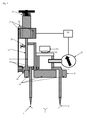
- FIG. 1 shows in a suction cup 1, which extends from its first end 2, on which the opening 3 is clamped to its second end 4, a stop 10, the stopper portions 11 has.
- the stopper portions 11 are guided by the guide member 12 guided along the suction cup 1 slidably.
- the guide element 12 is shown here by way of example as a guide rod 13, which is guided in at least one bore as a guide 14.
- the guide member 12 may be a pivot lever which is pivotable about a pivot bearing 14 as a guide, so that the stopper 10 is displaceable, for example, on an arcuate path.
- the opening 3 of the suction cup 1 extends in a plane at the first end 2 of the suction cup 1 and is surrounded by a circumferential cutting edge or sealing lip 5.
- the stopper portions 11 may have apertures 15 and be formed for example as a grid. Such apertures 15 are preferred at least in arranged within the suction cup 1 stop portions 11, since negative pressure can act through these openings 15.
- the guide element 12 is connected to a locking device 17, for example guided in the locking device 17.
- the locking device 17 may be connected to a carrier (not shown) to which the suction cup 1 is attached; Preferably, the guide element 12 is guided on the carrier.
- the locking device 17 is connected to the control device 20, which is connected to the connected in the interior of the suction cup 1 pressure gauge 21 for transmitting a signal for the pressure measured by the pressure gauge 21.
- the control device 20 is set up, upon transmission of a signal of the pressure gauge 21, which corresponds to a predetermined first negative pressure, the locking device 17 with a signal for fixing the guide member 12 to control.
- the locking device 17 may optionally have a brake which brakes the movement of the guide element before reaching or determining a predetermined first negative pressure within the suction cup 1, in particular when determining a predetermined second negative pressure by the pressure gauge 21.
- the locking device 17 may be formed as a clamping device, which can set the guide member 12 controlled non-positively and optionally the guide member 12, e.g. by friction, braking, e.g. controlled in dependence on the second negative pressure determined by the pressure gauge. In this embodiment, the locking device additionally forms a brake.
- a restoring element 18 is shown, which moves the guide element 12 when the locking device 17 is released in a first position in which the stop 10 is not loaded by a food.
- the return element 18 can, as shown schematically by a spring, load the guide element 12 or the locking device 17 in the direction of the first end 2 or against the opening 3.
- the return element 18 is controlled by the control device 20, for example in the form of a servomotor, and is adapted to allow a displacement of the guide member 12 in the direction of the second end 4 of the suction cup 1 without much resistance, in particular substantially without drag the displacement of the stop 10 against the second end 4 to allow.
- the device has a valve 30 which is arranged in the line which connects the suction cup 1 with a vacuum source 31.
- the valve 30 may be controlled by the controller 20 in response to a signal from the pressure gauge 21.
- An optional switch 19 is mounted as an end position sensor on the suction pad, e.g. on the guide in the region of the movement path of the stop 10, so that the switch 19 is actuated when the stop 10 approaches.
- the control device 21 may be configured to control the vacuum source 30 and / or the valve 31 depending on a signal of the switch 19.
- the switch 19 is in the end position of the movement path of the guide element 12, e.g. arranged with the guide member stop 10 and the control device 21 is adapted to reduce the power of the vacuum source 31 and / or close the valve 30 at a signal of the switch 19 for the end position of the guide member 12.
- FIG. 1 shows an optional damping device 25, which is adapted to delay the movement of the guide member 12 in the direction of the cutting edge 5, or to allow the movement only with a predetermined maximum distance per unit time.
- a damping device 25 may be, for example, a member loaded against and rubbing against the guide element 12.
- the optional damping device 25 is also loaded against other sections of the guide element 12.
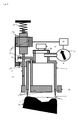
- FIG. 2 shows the device in a first position or rest position, in which the stop 10 is positioned in the plane in which the opening 3 extends.
- a position of the stop 10 may also be referred to as an ejection position, since such a position can also be assumed by actuation of the return element 18, which moves the stop 10 against the action of a negative pressure from the second end 4 in the plane of the opening 3 or beyond ,
- FIGS. 1 and 2 show as a preferred embodiment the arrangement of a switch 23 which is arranged upon movement of the stopper 10 from its unloaded end position (as in FIG FIG. 2 shown) against the second end 4 of the suction cup 1, to be actuated, wherein the signal of the switch 23 is used to turn on the vacuum source 31 and / or to open the valve 30.
- the switch 23 is used to control the vacuum applied in the suction cup 1 only when the stopper 10 is loaded by a food or moved from its rest position against the second end 4.
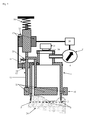
- FIG. 3 shows the embodiment of FIG. 2 in a second position, in which without a food that rests against the opening 3, the stop 10 is removed from the first end 2 and the stopper 10 is in its end position.
- the stopper 10 actuates the switch 19, so that its signal for controlling the vacuum source 31, in particular for the reduction or disengagement and / or closing of the valve 30 can be used.
- This shows the advantage of the switch 19, since without concern of a food at the opening 3, a voltage applied to the suction cup negative pressure is inoperative.
- the limit switch 23 can switch on the vacuum source 31 or open the valve 30, so that it is preferred that the signal of the switch 19 dominates the signal of the switch 23 and in the end position shown here switches off the vacuum source 31 or the Valve 30 can be closed.
- FIGS. 4 and 5 For the method of holding food with the holding device, the approximation of a sausage end 24 as an example of a food having an uneven surface to the opening 3 of the suction cup 1.
- position of the stop 10 is still in a section, right in FIG. 4 shown, a distance of this food 24 is formed to the cutting edge or sealing lip 5, which includes the opening 3.
- air at negative pressure applied to the suction cup 1, between the sausage end 24 and the cutting edge 5 flow into the suction cup 1.
- the food 24 is sealingly against the cutting edge or sealing lip 5 and therefore allows for the same power of the vacuum source 31 a lower pressure within the suction cup 1.
- FIGS. 4 and 5 The penetrated into the sausage end 24 portions of the cutting edge 5 are in FIGS. 4 and 5 shown in dashed lines.
- the stopper 10 By moving the food 24 from the first end 2 in the direction of the second end 4 of the suction cup 1, the stopper 10 is moved along the suction cup 1 in the direction of the second end 4 of the suction cup 1.
- the guide element 12 connected to the stop 10 can be fixed in its position by the locking device 17 upon reaching a predetermined pressure, ie a sufficient negative pressure for holding the food.
- the locking device 17 is controlled by the control device 20 depending on the signal of the pressure gauge 21 for fixing the guide member 12.
- valve 30 are closed by the control device 20.
- the controlled by the controller 20 valve 30 is generally preferred because it serves the energy saving, because the vacuum source 31 is not continuously, in particular dependent on a signal of the pressure gauge is actuated, or applies negative pressure to the suction cup.
- control device 20 is arranged to close without displacement of the stop 12 from its ejection position or first position in which the stop is not displaced in the direction of the second end of the suction cup.
- the valve 30 is closed when the holding device is not disposed against a food that loads the stopper 10.
Landscapes
- Life Sciences & Earth Sciences (AREA)
- Forests & Forestry (AREA)
- Engineering & Computer Science (AREA)
- Mechanical Engineering (AREA)
- Manipulator (AREA)
- Hooks, Suction Cups, And Attachment By Adhesive Means (AREA)
Abstract
Description
- Die vorliegende Erfindung betrifft eine Haltevorrichtung, insbesondere zur Verwendung als Greifer für Lebensmittel, sowie ein Verfahren zum Halten von Gegenständen, insbesondere von Lebensmitteln.
- Die Haltevorrichtung und das Verfahren zeichnen sich dadurch aus, dass mittels einer Saugglocke, die mit einer Unterdruckquelle verbunden ist, ein sicheres Halten unregelmäßig geformter Gegenstände, insbesondere von Lebensmitteln erreicht wird, wobei die Wechselwirkung der Haltevorrichtung mit dem Gegenstand kontrolliert wird.
- Bekannte Haltevorrichtungen dichten unregelmäßige Gegenstände, insbesondere Lebensmittel, mittels einer Gummilippe oder Schneidkante ab, wobei ein vorbestimmter Unterdruck angelegt wird oder geregelt wird. Die bekannten Haltevorrichtungen sind dahingehend nachteilig, dass das Anliegen des Gegenstands, insbesondere eines Lebensmittels, gegen eine Gummilippe oder Schneidkante nicht gesteuert wird.
- Die
US 3,880,295 beschreibt ringförmige Ausnehmungen, zwischen denen ringförmig geschlossene scharfe Kanten hervorstehen, als Haltevorrichtung für Lebensmittel. Die Ausnehmungen sind mittels Bohrungen mit einer Unterdruckkammer verbunden. Die Ausnehmungen sind mit einer Unterdruckkammer verbunden, wobei in eine Kammer ein Stift ragt, mit dem eine die Verbindungen zur Unterdruckkammer überdeckende Platte verbunden ist, sodass bei Annäherung eines Lebensmittels an die Ausnehmungen der Stift bewegt wird und dessen Platte die Verbindungen zur Unterdruckkammer freigibt. - Die
DE 10024913 A1 beschreibt für eine Schneidemaschine eine Haltevorrichtung, die mit Unterdruck beaufschlagbare Saugnäpfe aufweist. - Die
US 6024392 beschreibt einen Sauggreifer, bei dem eine elastische Saugglocke an einem Kolbenelement befestigt ist, das verschieblich in einer Bohrung gehalten ist und bei Belastung gegen einen Gegenstand in die Bohrung geschoben wird und dadurch einen Strömungsweg für Unterdruck öffnet. Beim Verschieben des Kolbenelements in Gegenrichtung wird der Strömungskanal für Unterdruck geschlossen. Weiter werden allgemein Näherungsschalter beschrieben, die bei Annäherung eines Sauggreifers an einen Gegenstand Unterdruck anliegen lassen. - Die
EP 2554344 A1 beschreibt einen Sauggreifer mit einer Saugglocke, an der ein Anschlag für ein angesaugtes Lebensmittel angeordnet ist, der mittels eines Stellantriebs veschieblich ist. - Die
DE 29916647 U1 beschreibt eine Saugeinrichtung, bei der ein vom Unterdruck abhängig gesteuerter Mikroschalter die Vakuumpumpe steuert. - Der Erfindung stellt sich daher die Aufgabe, eine verbesserte Haltevorrichtung und ein Verfahren zum Halten bereitzustellen, die das Anliegen eines Lebensmittels an eine Saugglocke verbessert und bevorzugt das Anliegen des Lebensmittels für ein sicheres Halten steuert. Eine bevorzugte Aufgabe liegt darin, ein Verfahren und eine Haltevorrichtung dafür bereitzustellen, mit der das Anliegen unregelmäßig geformter Lebensmittel an der Saugglocke steuerbar ist, sodass das Anliegen des Lebensmittels an einer Dichtlippe oder Schneidkante der Saugglocke bis zu einem minimal erforderlichen Ausmaß erfolgt, das für sicheres Halten erforderlich ist.
- Die Erfindung löst die Aufgabe mit den Merkmalen der Ansprüche und stellt insbesondere eine Haltevorrichtung bereit, die eine Saugglocke aufweist, an die eine Unterdruckquelle anzuschließen ist, wobei die Saugglocke an ihrer Öffnung eine umlaufende Dichtlippe oder Schneidkante aufweist. Bevorzugt ist die Dichtlippe bzw. Schneidkante in einer Ebene angeordnet und entsprechend ist die Öffnung in einer Ebene aufgespannt.
- Die Saugglocke zeichnet sich durch einen Anschlag aus, der entlang der Saugglocke in Richtung auf die Öffnung und von der Öffnung entlang der Saugglocke verschieblich geführt ist. Der Anschlag ist durch ein Führungselement verschieblich geführt, das mit einer Feststelleinrichtung verbunden ist bzw. eine Feststelleinrichtung aufweist. Bei Annäherung bzw. Anliegen eines Gegenstands an der Öffnung der Saugglocke wird der Anschlag von der Öffnung am ersten Ende in Richtung auf das vom ersten Ende beabstandete zweite Ende der Saugglocke verschoben, z.B. weiter in die Saugglocke verschoben.
- Mit der Saugglocke ist ein Druckmesser verbunden, der den Druck innerhalb der Saugglocke misst, der insbesondere ein Unterdruck ist, und das Signal für den gemessenen Druck an eine Steuereinheit überträgt. Die Feststelleinrichtung ist von der Steuereinheit gesteuert, dass die Feststelleinrichtung bei Anliegen eines vorbestimmten Unterdrucks, der auch als erster Unterdruck bezeichnet wird, betätigt wird und das Führungselement in seiner Stellung festgelegt wird, wodurch der mittels des Führungselements mit der Feststelleinrichtung verbundene Anschlag in seiner Stellung relativ zur Saugglocke festgelegt wird. Auf diese Weise erlaubt die Haltevorrichtung ein Verfahren zum Halten von Gegenständen, insbesondere von Lebensmitteln an ihrer Öffnung, wobei das Lebensmittel nur soweit in die Saugglocke gezogen wird und nur soweit gegen eine umlaufend an der Öffnung der Saugglocke angeordnete Dichtlippe bzw. Schneidkante durch den in der Saugglocke anliegenden Unterdruck gezogen wird, bis ein vorbestimmter Unterdruck erreicht ist. Ein weiteres Eindringen des Lebensmittels, das im Bereich des Anliegens an eine Dichtlippe oder Schneidkante in der Öffnung beeinträchtigt wird, wird auf diese Weise vermieden, während ein für einen vorbestimmten Druck innerhalb der Saugglocke erforderliches Anliegen des Lebensmittels an der Dichtlippe bzw. Schneidkante der Öffnung erfolgt. Dabei ist der vorbestimmte Druck ein Unterdruck innerhalb der Saugglocke, bei dem ein zuverlässiges Halten des Lebensmittels an der Saugglocke festgestellt wurde. Insbesondere ist der vorbestimmte Druck ein in der Saugglocke anliegender Unterdruck, bei dem das Lebensmittel derart gegen die Dichtlippe oder Schneidkante der Öffnung gezogen wird, dass das Lebensmittel die Öffnung dicht überdeckt, und insbesondere keine Leckagen zwischen Dichtlippe bzw. Schneidkante und Lebensmittel belässt. Dies ist insbesondere in Verfahren zum Halten eines Lebensmittels vorteilhaft, das luftdurchlässig ist und/oder eine Oberfläche aufweist, die uneben ist und/oder nicht bündig an der Ebene der Öffnung anliegt, die von der Dichtlippe oder Schneidkante aufgespannt wird, wobei die Feststelleinrichtung das Führungselement bei Erreichen eines vorbestimmten Unterdrucks innerhalb der Saugglocke festlegt.
- Bevorzugt ist die Feststelleinrichtung eingerichtet, bei einem zweiten vorbestimmten Unterdruck die Bewegung des Führungselements zu bremsen, z.B. durch Reibung, insbesondere bis zum Anliegen eines vorbestimmten Unterdrucks, bei dem die Feststelleinrichtung das Führungselement festlegt. Dabei ist der zweite vorbestimmte Unterdruck ein höherer Druck absolut bzw. eine geringere Druckdifferenz zum Umgebungsdruck als der (erste) Unterdruck, bei dem die Feststelleinrichtung festgelegt wird. In dieser Ausführungsform wird die Feststelleinrichtung abhängig vom Signal des Druckmessers für den Unterdruck in der Saugglocke gesteuert, dass bei Anliegen eines zweiten vorbestimmten Unterdrucks das Führungselement gebremst wird und anschließend bei Anliegen des vorbestimmten (ersten) Unterdrucks die Feststelleinrichtung das Führungselement festlegt. Diese Ausführungsform ist insbesondere bei Verfahren zum Halten schwerer Lebensmittel vorteilhaft, die z.B. 1 - 20 kg Stückgewicht aufweisen, da ein plötzliches Festlegen des Führungselements durch die Feststelleinrichtung zur Beeinträchtigung der Form und/oder des Anliegens des Lebensmittels an der Saugglocke führen kann, insbesondere bei elastischen oder weichen Lebensmitteln. Der zweite Unterdruck kann z.B. 70% bis 95% des ersten Unterdrucks sein, bevorzugt 80% bis 90%, wenn der Unterdruck als Differenzdruck zum Umgebungsdruck bestimmt ist. Bevorzugt ist die Feststelleinrichtung eingerichtet, die Bewegung des Führungselements auf das zweite Ende der Saugglocke zu bremsen, insbesondere einstellbar und/oder gesteuert zu bremsen, z.B. durch eine hydraulische, pneumatische, mechanische oder elektronisch gesteuerte Drossel. Weiter bevorzugt ist die Feststelleinrichtung eingerichtet, die Bewegung des Führungselements gesteuert, insbesondere abhängig vom Erreichen des ersten vorbestimmten Unterdrucks, der durch die Druckmesseinrichtung bestimmt wird, vollständig anzuhalten bzw. zu sperren und das Führungselement festzulegen. Dies verhindert ein zu plötzliches Einsaugen des Lebensmittels, bzw. das Eindringen der Saugglocke in das Produkt über das Maß hinaus, das zum Abdichten erforderlich ist, das insbesondere als Anliegen bzw. Bestimmung eines ersten Unterdrucks vorbestimmt ist.
- Die Haltevorrichtung ist insbesondere für ein Verfahren zum Halten von Lebensmitteln vorteilhaft, die eine unregelmäßig geformte Oberfläche haben und starr sind, sodass sie sich nicht an die Öffnung bzw. Dichtlippe oder Schneidkante anlegen. Dies sind beispielsweise feste Lebensmittel, wie beispielsweise harte Wurst und Räucherwaren, Hartkäse, sowie Aufschnittwurst, jeweils optional in Stangen- oder Blockform, und rohes Fleisch sowie gefrostete Lebensmittelriegel. Entsprechend ist die Haltevorrichtung insbesondere zur Verwendung als Greifer für Lebensmittel einer Schneidemaschine geeignet, wobei die Lebensmittel eine unebene und/oder unelastische bzw. starre Oberfläche aufweisen, die gegen die Schneidkante bzw. Dichtlippe anliegt.
- Die Saugglocke ist bevorzugt an einem Träger befestigt. Das Führungselement kann an einer an der Saugglocke und/oder einer mit dem Träger verbundenen Führung geführt sein, sodass das Führungselement und der damit verbundene Anschlag entlang der Saugglocke verschieblich geführt sind. Das Führungselement kann eine Führungsstange sein und die Führung eine Längsführung, z.B. eine Bohrung, oder das Führungselement kann ein Schwenkhebel sein und die Führung ein Schwenklager.
- Die Saugglocke weist eine Öffnung an ihrem ersten Ende auf und eine Wand, die sie mit ihrem zweiten Ende verbindet. Die Wand ist bevorzugt zylindrisch. Die Öffnung ist bevorzugt kreisförmig. Bevorzugt ist der Anschlag vom ersten Ende in Richtung auf das zweite Ende der Saugglocke verschieblich geführt, z.B. über einen Abschnitt von 10 bis 90% des Abstands der Öffnung bis zum zweiten Ende. Der Anschlag kann innerhalb und/oder außerhalb der Saugglocke angeordnete Anschlagsabschnitte aufweisen, die bevorzugt eine dem ersten Ende der Saugglocke zugewandte Oberfläche aufweisen, die in einer gemeinsamen Ebene angeordnet ist, insbesondere parallel zur Ebene der Öffnung der Saugglocke. Die Unterdruckquelle ist vorzugsweise am zweiten Ende der Saugglocke angeschlossen.
- Der Anschlag bzw. die Anschlagsabschnitte können massiv oder durchlässig sein, beispielsweise in Form eines Gitters.
- Die Feststelleinrichtung kann mit dem Träger verbunden sein, sodass die Feststelleinrichtung eingerichtet ist, das Führungselement gegenüber dem Träger in einer Stellung gesteuert festzulegen und bevorzugt, bei Anliegen eines zweiten Unterdrucks, gesteuert zu bremsen. Besonders bevorzugt ist die Verwendung der Haltevorrichtung als Greifer für eine Schneidemaschine mit einem Schneidelement, die insbesondere ein Slicer von Wurst- und Fleischwaren oder Käse ist. Entsprechend sind erfindungsgemäß Slicer für Lebensmittel bevorzugt, die eine erfindungsgemäße Haltevorrichtung aufweisen. Dabei erreicht die Haltevorrichtung die Minimierung von Verschnitt und/oder Reststücken von Lebensmitteln in Stangen- oder Blockform bei automatischen Schneidvorgängen mittels eines Slicers
- Die Feststelleinrichtung kann ein Rückstellelement aufweisen, beispielsweise in Form einer Feder, das gegenüber einem mit dem Träger verbundenen Teil der Haltevorrichtung wirkt. Optional besteht das Rückstellelement aus einer Druckfeder, die bei Bewegung des Führungselements von der Öffnung bzw. von der Schneidkante weg gespannt wird. Bevorzugt ist das Rückstellelement motorisch oder durch Druckluft angetrieben, z.B. kann das Rückstellelement ein mit Druckluft betriebener Druckzylinder sein. Optional ist das Rückstellelement zur Verschiebung des Führungselements in Abhängigkeit von der Entfernung eines Schneidelements von der Öffnung gesteuert.
- Der Druckmesser ist mit dem Innenraum der Saugglocke verbunden, wahlweise in dem Abschnitt der Saugglocke, über den der Anschlag verschieblich ist, oder in einem Abschnitt der Saugglocke zwischen der Unterdruckquelle und dem Anschlag.
- Bevorzugt weist die Saugglocke ein Ventil auf, das die Leitung zur Unterdruckquelle kontrolliert und besonders bevorzugt von der Steuereinheit in Abhängigkeit von dem Signal des Druckmessers gesteuert ist.
- Im Verfahren zum Halten von Lebensmitteln, insbesondere unter Verwendung der Haltevorrichtung, wird die Saugglocke mit ihrer Öffnung gegen ein Lebensmittel angeordnet, bis die Saugglocke das Lebensmittel berührt. An der Saugglocke liegt Unterdruck an, sodass das Lebensmittel durch den in der Saugglocke wirkenden Unterdruck gegen die an der Öffnung der Saugglocke umlaufend angeordnete Dichtlippe oder Schneidkante gezogen wird. In einer ersten Stellung liegt der Anschlag am ersten Ende der Saugglocke und ist gegen das Lebensmittel angeordnet. Wenn das Lebensmittel im Bereich der Öffnung durch den Unterdruck in die Saugglocke gezogen wird, wird der Anschlag in Richtung auf das zweite Ende der Saugglocke verschoben. Der Druckmesser übermittelt ein Signal für den in der Saugglocke anliegenden Druck an die Steuereinrichtung, die die Feststelleinrichtung bei Erreichen eines vorgegebenen Drucks ansteuert und diese das Führungselement festlegt. In dieser Ausführung wird die Feststelleinrichtung abhängig vom Signal des Druckmessers gesteuert in der Stellung festgelegt, in der der vorbestimmte Druck innerhalb der Saugglocke anliegt, sodass der Anschlag dann in der zweiten Stellung durch das Führungselement festgelegt wird, wenn der vorbestimmte Druck erreicht wird. Da bei anliegendem Unterdruck ein vorbestimmter Druck erst dann vom Druckmesser gemessen wird, wenn eine hinreichende Anordnung des Lebensmittels gegen die Dichtlippe bzw. Schneidkante der Öffnung anliegt und die Öffnung dichtend überdeckt, begrenzt der Anschlag in der zweiten Stellung die Bewegung des Lebensmittels in die Saugglocke. Bevorzugt weist die Halteeinrichtung eine Dämpfungseinrichtung, z.B. Dämpfungselement auf, das die Bewegung des Anschlags bzw. des Führungselements nur mit einer vorbestimmten maximalen Wegstrecke pro Zeiteinheit zulässt (z.B. bis zu 2 mm/s oder bis zu 15 mm/s). Die Dämpfungseinrichtung kann eingerichtet sein, die Bewegung des Anschlags bzw. des damit verbundenen Führungselements nur mit einer vorbestimmten maximalen Wegstrecke pro Zeiteinheit zuzulassen, wobei die Bewegung bevorzugt die Bewegung von der Öffnung der Saugglocke weg ist. Eine Dämpfungseinrichtung ist dahingehend vorteilhaft, dass für die Elemente der Vorrichtung, insbesondere für den Druckmesser, die Steuereinheit und/oder für die Feststelleinrichtung eine vorbestimmte minimale Zeit einstellbar ist, die deren Aktivität bzw. Betätigung während des Verfahrens zum Halten eines Lebensmittels erlaubt.
- Die Feststelleinrichtung kann eine abhängig vom Druckmesser gesteuerte Bremseinrichtung sein, die beispielsweise das Führungselement gesteuert festlegt. Daher kann die Feststelleinrichtung das Führungselement in einer Stellung kraftschlüssig, insbesondere reibschlüssig festlegen, sodass das Führungselement mit vorbestimmtem Widerstand gegen ein weiteres Verschieben gehemmt wird. Die Feststelleinrichtung kann eine Klemmeinrichtung und/oder Verrastungseinrichtung sein, die optional vorbestimmte Raststellungen entlang des Führungselements aufweist und zur Verrastung in diese eingreift. Bevorzugt ist die Feststelleinrichtung eingerichtet, in den Raststellungen zu klemmen oder in diese einzugreifen. Raststellungen können z.B. entlang des Führungselements angeordnete Ausnehmungen und/oder Vorsprünge aufweisen oder daraus gebildet sein, in denen die Feststelleinrichtung das Führungselement klemmen oder mit diesem verrasten kann.Das Rückstellelement ist bevorzugt gesteuert angetrieben und eingerichtet, das Führungselement zumindest in die erste Stellung zu bewegen, weiter bevorzugt über die erste Stellung hinaus auch über die Öffnungsebene der Saugglocke hinaus. In dieser Ausführungsform kann das Rückstellelement als Auswerfeinrichtung für Lebensmittel dienen. Dies ist insbesondere in Ausführungsformen bevorzugt, in denen die Öffnung eine umlaufende Schneidkante aufweist und bei Anordnung gegen ein Lebensmittel in dieses eingreift.
- Besonders bevorzugt ist eine als Auswerfeinrichtung verwendete Rückstelleinrichtung in Abhängigkeit von der Position des Schneidelements eines Slicers gesteuert, der die Haltevorrichtung aufweist. Eine solche Auswerfeinrichtung ist bevorzugt gesteuert, den Anschlag in Richtung auf die Öffnung der Saugglocke zu verschieben, optional über die Öffnung des Sauggreifers hinaus, wenn sich das Schneidelement des Slicers bis auf einen vorbestimmten Abstand an die Haltevorrichtung angenähert ist.
- Der Druck, bei dem die Feststelleinrichtung das Führungselement festlegt, wird auch als erster Unterdruck bezeichnet. Bevorzugt wird die Feststelleinrichtung gesteuert, bei einem zweiten vorbestimmten Unterdruck die Bewegung des Führungselements zu bremsen, z.B. durch Reibung, insbesondere bis zum Anliegen eines vorbestimmten ersten Unterdrucks, bei dem die Feststelleinrichtung das Führungselement festlegt. Dabei ist der zweite vorbestimmte Unterdruck ein höherer Druck absolut bzw. eine geringere Druckdifferenz zum Umgebungsdruck als der erste Unterdruck, bei dem die Feststelleinrichtung festgelegt wird. In dieser Ausführungsform wird die Feststelleinrichtung abhängig vom Signal des Druckmessers für den Unterdruck in der Saugglocke zum Bremsen des Führungselements gesteuert, so dass bei Anliegen eines zweiten vorbestimmten Unterdrucks gebremst wird und anschließend bei Anliegen des vorbestimmten ersten Unterdrucks die Feststelleinrichtung das Führungselement festlegt. Der zweite Unterdruck kann z.B. 70% bis 95% des ersten Unterdrucks sein, bevorzugt 80% bis 90%, wenn der Unterdruck als Differenzdruck zum Umgebungsdruck bestimmt ist.
- Optional weist die Haltevorrichtung einen Schalter auf, der abhängig von der Position des Anschlags betätigt wird und das Ventil, das zwischen der Saugglocke und der Unterdruckquelle angeordnet ist und/oder die Unterdruckquelle (31) abhängig vom Signal des Schalters steuert. Ein solcher Schalter kann z.B. ein Lagesensor oder Endlagenschalter sein, der die Stellung des Anschlags oder der Führungseinrichtung relativ zur Saugglocke detektiert. Der Schalter kann an einem mit der Saugglocke und/oder der Feststelleinrichtung verbundenen Träger festgelegt sein, wobei z.B. die Führungseinrichtung z.B. Vorsprünge oder Ausnehmungen als vom Schalter detektierbare lagespezifische Elemente aufweist.
- Die Erfindung wird nun genauer mit Bezug auf die Figuren beschrieben, die schematisch in
-
Figur 1 einen Schnitt durch eine erfindungsgemäße Vorrichtung, -
Figur 2 einen weiteren Schnitt durch eine erfindungsgemäße Vorrichtung, -
Figur 3 die Vorrichtung vonFigur 2 mit einer anderen Stellung des Anschlags und - in
Figuren 4 und5 die erfindungsgemäße Vorrichtung im Schnitt beim Verfahren zum Halten eines Lebensmittels zeigen. - In den Figuren bezeichnen gleiche Bezugsziffern funktionsgleiche Elemente.
-
Figur 1 zeigt in einer Saugglocke 1, die sich von ihrem ersten Ende 2, an dem die Öffnung 3 aufgespannt ist, zu ihrem zweiten Ende 4 erstreckt, einen Anschlag 10, der Anschlagsabschnitte 11 aufweist. Die Anschlagsabschnitte 11 sind mittels des Führungselements 12 geführt entlang der Saugglocke 1 verschieblich. Das Führungselement 12 ist hier beispielhaft als Führungsstange 13 gezeigt, die in zumindest einer Bohrung als Führung 14 geführt ist. Alternativ kann das Führungselement 12 ein Schwenkhebel sein, der um ein Schwenklager als Führung 14 schwenkbar ist, sodass der Anschlag 10 beispielsweise auf einer bogenförmigen Bahn verschieblich ist. - Die Öffnung 3 der Saugglocke 1 erstreckt sich in einer Ebene am ersten Ende 2 der Saugglocke 1 und ist von einer umlaufenden Schneidkante oder Dichtungslippe 5 umfasst.
- Die Anschlagsabschnitte 11 können Durchbrechungen 15 aufweisen und beispielsweise als Gitter ausgebildet sein. Solche Durchbrechungen 15 sind zumindest in innerhalb der Saugglocke 1 angeordneten Anschlagsabschnitten 11 bevorzugt, da Unterdruck durch diese Durchbrechungen 15 wirken kann.
- Das Führungselement 12 ist mit einer Feststelleinrichtung 17 verbunden, beispielsweise in der Feststelleinrichtung 17 geführt. Die Feststelleinrichtung 17 kann mit einem Träger (nicht gezeigt) verbunden sein, an dem auch die Saugglocke 1 befestigt ist; bevorzugt ist auch das Führungselement 12 an dem Träger geführt.
- Die Feststelleinrichtung 17 ist mit der Steuereinrichtung 20 verbunden, die mit dem in dem Innenraum der Saugglocke 1 verbundenen Druckmesser 21 zur Übermittlung eines Signals für den vom Druckmesser 21 gemessenen Druck verbunden ist.
- Die Steuereinrichtung 20 ist eingerichtet, bei Übermittlung eines Signals des Druckmessers 21, das einem vorbestimmten ersten Unterdruck entspricht, die Feststelleinrichtung 17 mit einem Signal zum Festlegen des Führungselements 12 anzusteuern. Generell kann die Feststelleinrichtung 17 optional eine Bremse aufweisen, die vor Erreichen bzw. Bestimmen eines vorbestimmten ersten Unterdrucks innerhalb der Saugglocke 1, insbesondere bei Bestimmen eines vorbestimmten zweiten Unterdrucks durch den Druckmesser 21, die Bewegung des Führungselements bremst. Die Feststelleinrichtung 17 kann als Klemmvorrichtung ausgebildet sein, die das Führungselement 12 gesteuert kraftschlüssig festlegen kann und optional das Führungselement 12, z.B. durch Reibung, bremst, z.B. gesteuert in Abhängigkeit von dem durch den Druckmesser bestimmten zweiten Unterdruck. In dieser Ausführungsform bildet die Feststelleinrichtung zusätzlich eine Bremse aus.
- Entsprechend der bevorzugten Ausführungsform ist ein Rückstellelement 18 gezeigt, das das Führungselement 12 bei gelöster Feststelleinrichtung 17 in eine erste Stellung bewegt, in der der Anschlag 10 nicht durch ein Lebensmittel belastet ist.
- Das Rückstellelement 18 kann, wie schematisch durch eine Feder gezeigt, das Führungselement 12 bzw. die Feststelleinrichtung 17 in Richtung auf das erste Ende 2 bzw. gegen die Öffnung 3 belasten. Bevorzugt ist das Rückstellelement 18 von der Steuereinrichtung 20 gesteuert, beispielsweise in Form eines Stellmotors, und ist eingerichtet, eine Verschiebung des Führungselements 12 in Richtung auf das zweite Ende 4 der Saugglocke 1 ohne größeren Widerstand zuzulassen, insbesondere im Wesentlichen ohne Gegenkraft die Verschiebung des Anschlags 10 gegen das zweite Ende 4 zuzulassen.
- Dies ist vorteilhaft für die Effizienz des Verfahrens, da ansonsten ein Teil der durch die Unterdruckquelle 31 für den Unterdruck aufzubringenden Leistung zur Belastung eines Rückstellelements 18 bei der Verschiebung des Anschlags 10 gegen das zweite Ende 4 der Saugglocke 1 aufzubringen ist.
- Bevorzugt weist die Vorrichtung ein Ventil 30 auf, das in der Leitung angeordnet ist, die die Saugglocke 1 mit einer Unterdruckquelle 31 verbindet. Optional kann das Ventil 30 abhängig von einem Signal des Druckmessers 21 von der Steuereinrichtung 20 gesteuert sein.
- Ein optionaler Schalter 19 ist als Endlagefühler an dem Sauggreifer angebracht, z.B. an der Führung im Bereich der Bewegungsbahn des Anschlags 10, so dass der Schalter 19 bei Annäherung des Anschlags 10 betätigt wird. Optional kann die Steuereinrichtung 21 eingerichtet sein, abhängig von einem Signal des Schalters 19 die Unterdruckquelle 30 und/oder das Ventil 31 zu steuern. Bevorzugt ist der Schalter 19 in der Endlage der Bewegungsbahn des Führungselements 12, z.B. des mit dem Führungselement verbundenen Anschlags 10 angeordnet und die Steuereinrichtung 21 ist eingerichtet, bei einem Signal des Schalters 19 für die Endlage des Führungselements 12 die Leistung der Unterdruckquelle 31 zu vermindern und/oder das Ventil 30 zu schließen.
-
Figur 1 zeigt eine optionale Dämpfungseinrichtung 25, die eingerichtet ist, die Bewegung des Führungselements 12 in Richtung von der Schneidkante 5 weg, zu verzögern bzw. die Bewegung nur mit einer vorbestimmten maximalen Wegstrecke pro Zeiteinheit zuzulassen. Eine solche Dämpfungseinrichtung 25 kann z.B. ein gegen das Führungselement 12 belastetes und daran schleifendes Element sein. In den nachfolgenden Figuren ist die optionale Dämpfungseinrichtung 25 auch gegen andere Abschnitte des Führungselements 12 belastet. -
Figur 2 zeigt die Vorrichtung in einer ersten Stellung oder Ruhestellung, in der der Anschlag 10 in der Ebene positioniert ist, in der sich die Öffnung 3 erstreckt. Eine solche Position des Anschlags 10 kann auch als Auswerfstellung bezeichnet werden, da eine solche Position auch durch Betätigung des Rückstellelements 18 eingenommen werden kann, das den Anschlag 10 gegen die Wirkung eines Unterdrucks vom zweiten Ende 4 in die Ebene der Öffnung 3 oder darüber hinaus bewegt. - Die
Figuren 1 und2 zeigen als eine bevorzugte Ausführungsform die Anordnung eines Schalters 23, der eingerichtet ist, bei Bewegung des Anschlags 10 von dessen unbelasteter Endlage (wie inFigur 2 gezeigt) gegen das zweite Ende 4 der Saugglocke 1, betätigt zu werden, wobei das Signal des Schalters 23 eingesetzt wird, die Unterdruckquelle 31 anzuschalten und/oder das Ventil 30 zu öffnen. In dieser Ausführungsform dient der Schalter 23 zur Steuerung des in der Saugglocke 1 anliegenden Unterdrucks nur dann, wenn der Anschlag 10 durch ein Lebensmittel belastet bzw. aus seiner Ruhestellung gegen das zweite Ende 4 bewegt wird. -
Figur 3 zeigt die Ausführungsform vonFigur 2 in einer zweiten Stellung, in der ohne ein Lebensmittel, das an der Öffnung 3 anliegt, der Anschlag 10 vom ersten Ende 2 entfernt ist und der Anschlag 10 in seiner Endlage ist. Der Anschlag 10 betätigt den Schalter 19, so dass dessen Signal zur Steuerung der Unterdruckquelle 31, insbesondere zu deren Leistungsminderung bzw. Abschalten und/oder zum Schließen des Ventils 30 eingesetzt werden kann. Dies zeigt den Vorteil des Schalters 19, da ohne Anliegen eines Lebensmittels an der Öffnung 3 ein an der Saugglocke anliegender Unterdruck funktionslos ist. Der Endlagenschalter 23 kann in der hier gezeigten Anordnung die Unterdruckquelle 31 anschalten bzw. das Ventil 30 öffnen, so dass bevorzugt ist, dass das Signal des Schalters 19 das Signal des Schalters 23 dominiert und in der hier gezeigten Endlage die Unterdruckquelle 31 abgestellt bzw. das Ventil 30 geschlossen werden kann. - Die
Figuren 4 und5 zeigen für das Verfahren zum Halten von Lebensmitteln mit der Haltevorrichtung das Annähern eines Wurstendes 24 als Beispiel für ein Lebensmittel mit unebener Oberfläche an die Öffnung 3 der Saugglocke 1. In der inFigur 4 gezeigten Stellung des Anschlags 10 ist noch in einem Abschnitt, rechts inFigur 4 gezeigt, ein Abstand dieses Lebensmittels 24 zu der Schneidkante oder Dichtlippe 5 ausgebildet, die die Öffnung 3 umfasst. Entsprechend kann Luft bei Unterdruck, der an der Saugglocke 1 anliegt, zwischen dem Wurstende 24 und der Schneidkante 5 in die Saugglocke 1 strömen. Bei weiterer Annäherung des Lebensmittels 24 wie inFigur 5 gezeigt, liegt das Lebensmittel 24 dichtend an der Schneidkante bzw. Dichtlippe 5 an und erlaubt daher bei gleicher Leistung der Unterdruckquelle 31 einen geringeren Druck innerhalb der Saugglocke 1. Die in das Wurstende 24 eingedrungenen Anteile der Schneidkante 5 sind inFiguren 4 und5 gestrichelt dargestellt. Durch Bewegen des Lebensmittels 24 vom ersten Ende 2 in Richtung auf das zweite Ende 4 der Saugglocke 1 wird der Anschlag 10 entlang der Saugglocke 1 in Richtung auf das zweite Ende 4 der Saugglocke 1 verschoben. Das mit dem Anschlag 10 verbundene Führungselement 12 kann bei Erreichen eines vorbestimmten Drucks, d.h. eines für das Halten des Lebensmittels ausreichenden Unterdrucks, durch die Feststelleinrichtung 17 in seiner Stellung festgelegt werden. Dazu wird die Feststelleinrichtung 17 durch die Steuereinrichtung 20 abhängig vom Signal des Druckmessers 21 zum Festlegen des Führungselements 12 angesteuert. - Optional kann in der in
Figur 5 gezeigten zweiten Stellung des Anschlags 10 das Ventil 30 durch die Steuereinrichtung 20 geschlossen werden. Das durch die Steuereinrichtung 20 gesteuerte Ventil 30 ist generell bevorzugt, da es der Energieeinsparung dient, weil die Unterdruckquelle 31 nicht kontinuierlich, insbesondere abhängig von einem Signal des Druckmessers betätigt wird, bzw. Unterdruck an die Saugglocke anlegt. - Optional ist die Steuereinrichtung 20 eingerichtet, ohne Verschiebung des Anschlags 12 aus seiner Auswerfstellung oder ersten Stellung, in der der Anschlag nicht in Richtung auf das zweite Ende der Saugglocke verschoben ist, zu schließen. In dieser Ausführungsform wird das Ventil 30 geschlossen, wenn die Haltevorrichtung nicht gegen ein Lebensmittel angeordnet ist, dass den Anschlag 10 belastet.
-
- 1 Saugglocke
- 16 Träger
- 2 erstes Ende
- 17 Feststelleinrichtung
- 3 Öffnung
- 18 Rückstellelement
- 4 zweites Ende
- 19 Schalter
- 5 Schneidkante, Dichtungslippe
- 20 Steuereinrichtung
- 10 Anschlag
- 21 Druckmesser
- 11 Anschlagsabschnitte
- 23 Schalter für unbelastete Endlage
- 12 Führungselement
- 24 Wurstende
- 13 Führungsstange
- 25 Dämpfungseinrichtung
- 14 Führung
- 30 Ventil
- 15 Durchbrechungen
- 31 Unterdruckquelle
Claims (15)
- Haltevorrichtung mit einer an eine Unterdruckquelle (31) anschließbaren Saugglocke (1), an deren erstem Ende (2) eine Öffnung (3) von einer umlaufenden Schneidkante oder Dichtlippe (5) aufgespannt ist, mit einem mit dem Inneren der Saugglocke (1) verbundenen Druckmesser (21), gekennzeichnet durch einen entlang der Saugglocke (1) an einem Führungselement (12) verschieblich geführten Anschlag (10), wobei das Führungselement (12) mit einer abhängig von einem Signal des Druckmessers (21) für einen ersten an der Saugglocke (1) anliegenden Unterdruck gesteuerten Feststelleinrichtung (17) verbunden ist.
- Haltevorrichtung nach Anspruch 1, gekennzeichnet durch eine Dämpfungseinrichtung (25), die eingerichtet ist, die Bewegung des Führungselements (12) nur mit einer vorbestimmten maximalen Wegstrecke pro Zeiteinheit zuzulassen.
- Haltevorrichtung nach einem der voranstehenden Ansprüche, dadurch gekennzeichnet, dass entlang des Führungselements (12) Ausnehmungen und/oder Vorsprünge angeordnet sind und die Feststelleinrichtung (17) eine Klemmeinrichtung und/oder Verrastungseinrichtung ist, die eingerichtet ist, an den Ausnehmungen und/oder Vorsprüngen zu klemmen oder mit diesen zu verrasten.
- Haltevorrichtung nach einem der voranstehenden Ansprüche, dadurch gekennzeichnet, dass das Führungselement (12) mit einem Rückstellelement (18) verbunden ist, das eingerichtet ist, das Führungselement (12) in eine erste Stellung zu bewegen, in der der Anschlag (10) in der Ebene der Öffnung (3) positioniert ist oder in eine Stellung, in der der Anschlag (10) über die Ebene der Öffnung (3) hinaus positioniert ist.
- Haltevorrichtung nach einem der voranstehenden Ansprüche, dadurch gekennzeichnet, dass ein abhängig von einem Signal des Druckmessers (21) gesteuertes Ventil (30) zwischen der Saugglocke (1) und der Unterdruckquelle (31) angeordnet ist.
- Haltevorrichtung nach einem der voranstehenden Ansprüche, dadurch gekennzeichnet, dass die Feststelleinrichtung (17) eine abhängig von einem Signal des Druckmessers (21) für einen zweiten an der Saugglocke (1) anliegenden Unterdruck gesteuerte Bremse für das Führungselement (12) ist, wobei der zweite Unterdruck ein geringerer Differenzdruck zum Umgebungsdruck ist als der erste an der Saugglocke (1) anliegende Unterdruck.
- Haltevorrichtung nach einem der voranstehenden Ansprüche, gekennzeichnet durch einen Schalter (19, 23), der abhängig von der Position des Anschlags (10) betätigt wird und ein zwischen der Saugglocke (1) und der Unterdruckquelle (31) angeordnetes Ventil (30) und/oder die Unterdruckquelle (31) abhängig vom Signal des Schalters (19) gesteuert ist.
- Haltevorrichtung nach einem der voranstehenden Ansprüche, gekennzeichnet durch ein Rückstellelement (18), das das Führungselement (12) in Richtung auf die Öffnung (3) belastet.
- Verwendung einer Haltevorrichtung nach einem der voranstehenden Ansprüche als Greifer für Lebensmittel (24) einer Schneidemaschine, wobei die gegen die umlaufende Schneidkante oder Dichtlippe (5) anliegende Oberfläche des Lebensmittels (24) uneben ist.
- Verfahren zum Halten eines Lebensmittels (24) mittels einer Haltevorrichtung nach einem der voranstehenden Ansprüche, bei dem in einer ersten Stellung der Anschlag (10) zumindest in der Ebene der Öffnung (3) positioniert ist und die Haltevorrichtung gegen ein Lebensmittel angeordnet wird, wodurch der Anschlag (10) in Richtung auf das zweite Ende (4) der Saugglocke (1) in eine zweite Stellung verschoben wird, die näher an dem zweiten Ende (4) der Saugglocke (1) liegt, als dessen erste Stellung, wobei der Druckmesser (21) ein Signal für den Druck innerhalb der Saugglocke (1) erzeugt und die Feststelleinrichtung (17) abhängig vom Signal des Druckmessers (21) betätigt wird und das Führungselement (12) festlegt.
- Verfahren nach Anspruch 10, dadurch gekennzeichnet, dass die Vorrichtung einen Schalter (19) aufweist, der bei Verschieben des Anschlags (12) aus der ersten Stellung betätigt wird und die Unterdruckquelle (31) anstellt und/oder ein Ventil (30), das zwischen der Saugglocke (1) und der Unterdruckquelle (31) angeordnet ist, öffnet.
- Verfahren nach einem der Ansprüche 10 bis 11, dadurch gekennzeichnet, dass ein Rückstellelement (18) betätigt wird und auf das Führungselement (12) wirkt, dass der Anschlag (10) in Richtung auf die Öffnung (3) der Saugglocke (1) verschoben wird.
- Verfahren nach einem der Ansprüche 10 bis 12, dadurch gekennzeichnet, dass das Signal für den Druck innerhalb der Saugglocke (1), bei dem die Feststelleinrichtung (17) das Führungselement (12) festlegt, ein erster Unterdruck ist und dass die Feststelleinrichtung (17) abhängig von einem Signal des Druckmessers (21) für einen an der Saugglocke (1) anliegenden zweiten Unterdruck die Bewegung des Führungselements (12) bremst, wobei der zweite Unterdruck ein geringerer Differenzdruck zum Umgebungsdruck ist als der erste Unterdruck.
- Verfahren nach einem der Ansprüche 10 bis 13, dadurch gekennzeichnet, dass das Lebensmittel, während es an der Saugglocke angeordnet ist, in Scheiben geschnitten wird.
- Verfahren nach einem der Ansprüche 10 bis 14, dadurch gekennzeichnet, dass das Lebensmittel (24) luftdurchlässig ist und/oder eine Oberfläche aufweist, die uneben ist und/oder nicht bündig an der Ebene der Öffnung (3) anliegt, und die Feststelleinrichtung (17) das Führungselement (12) bei Erreichen eines vorbestimmten Unterdrucks innerhalb der Saugglocke (1) festlegt.
Applications Claiming Priority (1)
| Application Number | Priority Date | Filing Date | Title |
|---|---|---|---|
| DE102013215725.8A DE102013215725A1 (de) | 2013-08-08 | 2013-08-08 | Haltevorrichtung |
Publications (2)
| Publication Number | Publication Date |
|---|---|
| EP2842702A1 true EP2842702A1 (de) | 2015-03-04 |
| EP2842702B1 EP2842702B1 (de) | 2017-02-22 |
Family
ID=51292842
Family Applications (1)
| Application Number | Title | Priority Date | Filing Date |
|---|---|---|---|
| EP14180098.7A Not-in-force EP2842702B1 (de) | 2013-08-08 | 2014-08-06 | Haltevorrichtung |
Country Status (4)
| Country | Link |
|---|---|
| EP (1) | EP2842702B1 (de) |
| DE (1) | DE102013215725A1 (de) |
| DK (1) | DK2842702T3 (de) |
| ES (1) | ES2628236T3 (de) |
Cited By (2)
| Publication number | Priority date | Publication date | Assignee | Title |
|---|---|---|---|---|
| EP3366438A1 (de) * | 2017-02-07 | 2018-08-29 | Weber Maschinenbau GmbH Breidenbach | Greifer, schneidvorrichtung und verfahren zum schneiden eines produkts |
| WO2025002850A1 (de) * | 2023-06-26 | 2025-01-02 | Harburg-Freudenberger Maschinenbau Gmbh | Verfahren zum heben einer materialeinheit aus einer materialanordnung |
Families Citing this family (2)
| Publication number | Priority date | Publication date | Assignee | Title |
|---|---|---|---|---|
| CN108272360B (zh) * | 2018-01-30 | 2020-06-12 | 宁波金汤科技服务有限公司 | 一种自动刨片装置 |
| CN108972646A (zh) * | 2018-07-04 | 2018-12-11 | 朱力红 | 一种气缸式调节条形食品切片机构 |
Citations (6)
| Publication number | Priority date | Publication date | Assignee | Title |
|---|---|---|---|---|
| US3880295A (en) | 1973-11-08 | 1975-04-29 | Thermoplastic Engineering Inc | Vacuum gripper device for slicing machine |
| DE29916647U1 (de) | 1999-09-22 | 2000-01-05 | Herzog, Manfred, 88471 Laupheim | Vakuum-Handhabungs-Wechselvorrichtung |
| US6024392A (en) | 1996-01-23 | 2000-02-15 | Isi Norgren, Inc. | Vacuum cup actuator |
| DE10024913A1 (de) | 2000-05-19 | 2001-11-29 | Schindler & Wagner Gmbh & Co | Schneidmaschine für laibförmige Produkte |
| EP2554344A1 (de) | 2010-08-04 | 2013-02-06 | Deutsches Institut für Lebensmitteltechnik e.V. | Vorrichtung und Verfahren zum Halten von Lebensmitteln |
| EP2574576A1 (de) * | 2011-09-27 | 2013-04-03 | Uwe Reifenhäuser | Sauggreifer und Verfahren zum Reinigen eines Sauggreifers |
-
2013
- 2013-08-08 DE DE102013215725.8A patent/DE102013215725A1/de not_active Ceased
-
2014
- 2014-08-06 DK DK14180098.7T patent/DK2842702T3/en active
- 2014-08-06 ES ES14180098.7T patent/ES2628236T3/es active Active
- 2014-08-06 EP EP14180098.7A patent/EP2842702B1/de not_active Not-in-force
Patent Citations (6)
| Publication number | Priority date | Publication date | Assignee | Title |
|---|---|---|---|---|
| US3880295A (en) | 1973-11-08 | 1975-04-29 | Thermoplastic Engineering Inc | Vacuum gripper device for slicing machine |
| US6024392A (en) | 1996-01-23 | 2000-02-15 | Isi Norgren, Inc. | Vacuum cup actuator |
| DE29916647U1 (de) | 1999-09-22 | 2000-01-05 | Herzog, Manfred, 88471 Laupheim | Vakuum-Handhabungs-Wechselvorrichtung |
| DE10024913A1 (de) | 2000-05-19 | 2001-11-29 | Schindler & Wagner Gmbh & Co | Schneidmaschine für laibförmige Produkte |
| EP2554344A1 (de) | 2010-08-04 | 2013-02-06 | Deutsches Institut für Lebensmitteltechnik e.V. | Vorrichtung und Verfahren zum Halten von Lebensmitteln |
| EP2574576A1 (de) * | 2011-09-27 | 2013-04-03 | Uwe Reifenhäuser | Sauggreifer und Verfahren zum Reinigen eines Sauggreifers |
Cited By (4)
| Publication number | Priority date | Publication date | Assignee | Title |
|---|---|---|---|---|
| EP3366438A1 (de) * | 2017-02-07 | 2018-08-29 | Weber Maschinenbau GmbH Breidenbach | Greifer, schneidvorrichtung und verfahren zum schneiden eines produkts |
| EP3851260A1 (de) * | 2017-02-07 | 2021-07-21 | Weber Maschinenbau GmbH Breidenbach | Greifer für schneidvorrichtung |
| US11207792B2 (en) | 2017-02-07 | 2021-12-28 | Weber Maschinenbau Gmbh Breidenbach | Gripper, cutting apparatus and method for cutting a product |
| WO2025002850A1 (de) * | 2023-06-26 | 2025-01-02 | Harburg-Freudenberger Maschinenbau Gmbh | Verfahren zum heben einer materialeinheit aus einer materialanordnung |
Also Published As
| Publication number | Publication date |
|---|---|
| DE102013215725A1 (de) | 2015-02-12 |
| DK2842702T3 (en) | 2017-06-06 |
| ES2628236T3 (es) | 2017-08-02 |
| EP2842702B1 (de) | 2017-02-22 |
Similar Documents
| Publication | Publication Date | Title |
|---|---|---|
| DE102011012880B4 (de) | Hochleistungsschneidemaschine mit einem Greifer | |
| EP2842702B1 (de) | Haltevorrichtung | |
| DE102009016332A1 (de) | Greifer zur Anordnung an einem Roboterarm mit einer Produktzentrierung | |
| DE2018454A1 (de) | Verfahren und Vorrichtung zum Abbremsen von Verpackungsschläuchen, die von einem Füllrohr ablaufen | |
| DE102013114559B4 (de) | Schiebetürvorrichtung für ein kraftfahrzeug | |
| DE202007018801U1 (de) | Vorrichtung zum Verpacken von Reifen | |
| DE1602515A1 (de) | Verfahren und Vorrichtung zum Ziehen von Behaeltern | |
| EP3290365A1 (de) | Sauggreifer und verfahren zum gerifen elastischer scheiben | |
| DE102022114771A1 (de) | Aufschneide-Maschine sowie Verfahren zum Aufschneiden eines Produkt-Stückes in Scheiben | |
| EP0131741A2 (de) | Badewannenlift für Behinderte | |
| EP2842703B1 (de) | Sauggreifer mit Auswerfer für Lebensmittel | |
| DE2240530A1 (de) | Baeckereientformungsvorrichtung | |
| DE3608780C2 (de) | Vorrichtung zum Schneiden von Lebensmitteln | |
| EP4142986B1 (de) | Sauggreifer und unterdruckhandhabungsanlage | |
| WO2017137024A1 (de) | Küchenhobel und applikator | |
| DE102019104890A1 (de) | Elektromagnetische Bremse oder Kupplung | |
| DE202014102535U1 (de) | Kunststoffgreifer | |
| EP0290774B1 (de) | Kanalballenpresse | |
| DE3301317A1 (de) | Bremszylinder | |
| DE2747890C3 (de) | Vorrichtung zum Formen und Halten einer Banderole in einer Tiefziehform | |
| DE202009003197U1 (de) | Handführbare Antriebseinrichtung für ein Pressgerät | |
| DE3018138C2 (de) | ||
| DE102014101924B3 (de) | Vorrichtung zum stellungsvariablen Einspannen eines Werkstücks | |
| DE2460184A1 (de) | Einrichtung zum anformen einer randrille bzw. randsicke am offenen ende eines metallischen hohlkoerpers bzw. behaelters | |
| DE1234549B (de) | Servovorrichtung der Druckdifferenzbauart fuer Bremssysteme, insbesondere fuer Kraftfahrzeuge |
Legal Events
| Date | Code | Title | Description |
|---|---|---|---|
| 17P | Request for examination filed |
Effective date: 20140806 |
|
| AK | Designated contracting states |
Kind code of ref document: A1 Designated state(s): AL AT BE BG CH CY CZ DE DK EE ES FI FR GB GR HR HU IE IS IT LI LT LU LV MC MK MT NL NO PL PT RO RS SE SI SK SM TR |
|
| AX | Request for extension of the european patent |
Extension state: BA ME |
|
| PUAI | Public reference made under article 153(3) epc to a published international application that has entered the european phase |
Free format text: ORIGINAL CODE: 0009012 |
|
| R17P | Request for examination filed (corrected) |
Effective date: 20150611 |
|
| RBV | Designated contracting states (corrected) |
Designated state(s): AL AT BE BG CH CY CZ DE DK EE ES FI FR GB GR HR HU IE IS IT LI LT LU LV MC MK MT NL NO PL PT RO RS SE SI SK SM TR |
|
| GRAP | Despatch of communication of intention to grant a patent |
Free format text: ORIGINAL CODE: EPIDOSNIGR1 |
|
| INTG | Intention to grant announced |
Effective date: 20161007 |
|
| GRAS | Grant fee paid |
Free format text: ORIGINAL CODE: EPIDOSNIGR3 |
|
| GRAA | (expected) grant |
Free format text: ORIGINAL CODE: 0009210 |
|
| AK | Designated contracting states |
Kind code of ref document: B1 Designated state(s): AL AT BE BG CH CY CZ DE DK EE ES FI FR GB GR HR HU IE IS IT LI LT LU LV MC MK MT NL NO PL PT RO RS SE SI SK SM TR |
|
| REG | Reference to a national code |
Ref country code: GB Ref legal event code: FG4D Free format text: NOT ENGLISH |
|
| REG | Reference to a national code |
Ref country code: CH Ref legal event code: EP |
|
| REG | Reference to a national code |
Ref country code: AT Ref legal event code: REF Ref document number: 868900 Country of ref document: AT Kind code of ref document: T Effective date: 20170315 |
|
| REG | Reference to a national code |
Ref country code: IE Ref legal event code: FG4D Free format text: LANGUAGE OF EP DOCUMENT: GERMAN |
|
| REG | Reference to a national code |
Ref country code: DE Ref legal event code: R096 Ref document number: 502014002747 Country of ref document: DE |
|
| REG | Reference to a national code |
Ref country code: NL Ref legal event code: FP |
|
| REG | Reference to a national code |
Ref country code: DK Ref legal event code: T3 Effective date: 20170601 |
|
| REG | Reference to a national code |
Ref country code: LT Ref legal event code: MG4D |
|
| PG25 | Lapsed in a contracting state [announced via postgrant information from national office to epo] |
Ref country code: HR Free format text: LAPSE BECAUSE OF FAILURE TO SUBMIT A TRANSLATION OF THE DESCRIPTION OR TO PAY THE FEE WITHIN THE PRESCRIBED TIME-LIMIT Effective date: 20170222 Ref country code: LT Free format text: LAPSE BECAUSE OF FAILURE TO SUBMIT A TRANSLATION OF THE DESCRIPTION OR TO PAY THE FEE WITHIN THE PRESCRIBED TIME-LIMIT Effective date: 20170222 Ref country code: GR Free format text: LAPSE BECAUSE OF FAILURE TO SUBMIT A TRANSLATION OF THE DESCRIPTION OR TO PAY THE FEE WITHIN THE PRESCRIBED TIME-LIMIT Effective date: 20170523 Ref country code: FI Free format text: LAPSE BECAUSE OF FAILURE TO SUBMIT A TRANSLATION OF THE DESCRIPTION OR TO PAY THE FEE WITHIN THE PRESCRIBED TIME-LIMIT Effective date: 20170222 Ref country code: NO Free format text: LAPSE BECAUSE OF FAILURE TO SUBMIT A TRANSLATION OF THE DESCRIPTION OR TO PAY THE FEE WITHIN THE PRESCRIBED TIME-LIMIT Effective date: 20170522 |
|
| REG | Reference to a national code |
Ref country code: ES Ref legal event code: FG2A Ref document number: 2628236 Country of ref document: ES Kind code of ref document: T3 Effective date: 20170802 |
|
| REG | Reference to a national code |
Ref country code: FR Ref legal event code: PLFP Year of fee payment: 4 |
|
| PG25 | Lapsed in a contracting state [announced via postgrant information from national office to epo] |
Ref country code: PT Free format text: LAPSE BECAUSE OF FAILURE TO SUBMIT A TRANSLATION OF THE DESCRIPTION OR TO PAY THE FEE WITHIN THE PRESCRIBED TIME-LIMIT Effective date: 20170622 Ref country code: BG Free format text: LAPSE BECAUSE OF FAILURE TO SUBMIT A TRANSLATION OF THE DESCRIPTION OR TO PAY THE FEE WITHIN THE PRESCRIBED TIME-LIMIT Effective date: 20170522 Ref country code: SE Free format text: LAPSE BECAUSE OF FAILURE TO SUBMIT A TRANSLATION OF THE DESCRIPTION OR TO PAY THE FEE WITHIN THE PRESCRIBED TIME-LIMIT Effective date: 20170222 Ref country code: LV Free format text: LAPSE BECAUSE OF FAILURE TO SUBMIT A TRANSLATION OF THE DESCRIPTION OR TO PAY THE FEE WITHIN THE PRESCRIBED TIME-LIMIT Effective date: 20170222 Ref country code: RS Free format text: LAPSE BECAUSE OF FAILURE TO SUBMIT A TRANSLATION OF THE DESCRIPTION OR TO PAY THE FEE WITHIN THE PRESCRIBED TIME-LIMIT Effective date: 20170222 |
|
| PG25 | Lapsed in a contracting state [announced via postgrant information from national office to epo] |
Ref country code: RO Free format text: LAPSE BECAUSE OF FAILURE TO SUBMIT A TRANSLATION OF THE DESCRIPTION OR TO PAY THE FEE WITHIN THE PRESCRIBED TIME-LIMIT Effective date: 20170222 Ref country code: SK Free format text: LAPSE BECAUSE OF FAILURE TO SUBMIT A TRANSLATION OF THE DESCRIPTION OR TO PAY THE FEE WITHIN THE PRESCRIBED TIME-LIMIT Effective date: 20170222 Ref country code: EE Free format text: LAPSE BECAUSE OF FAILURE TO SUBMIT A TRANSLATION OF THE DESCRIPTION OR TO PAY THE FEE WITHIN THE PRESCRIBED TIME-LIMIT Effective date: 20170222 Ref country code: CZ Free format text: LAPSE BECAUSE OF FAILURE TO SUBMIT A TRANSLATION OF THE DESCRIPTION OR TO PAY THE FEE WITHIN THE PRESCRIBED TIME-LIMIT Effective date: 20170222 |
|
| REG | Reference to a national code |
Ref country code: DE Ref legal event code: R097 Ref document number: 502014002747 Country of ref document: DE |
|
| PG25 | Lapsed in a contracting state [announced via postgrant information from national office to epo] |
Ref country code: SM Free format text: LAPSE BECAUSE OF FAILURE TO SUBMIT A TRANSLATION OF THE DESCRIPTION OR TO PAY THE FEE WITHIN THE PRESCRIBED TIME-LIMIT Effective date: 20170222 Ref country code: PL Free format text: LAPSE BECAUSE OF FAILURE TO SUBMIT A TRANSLATION OF THE DESCRIPTION OR TO PAY THE FEE WITHIN THE PRESCRIBED TIME-LIMIT Effective date: 20170222 |
|
| PLBE | No opposition filed within time limit |
Free format text: ORIGINAL CODE: 0009261 |
|
| STAA | Information on the status of an ep patent application or granted ep patent |
Free format text: STATUS: NO OPPOSITION FILED WITHIN TIME LIMIT |
|
| 26N | No opposition filed |
Effective date: 20171123 |
|
| PG25 | Lapsed in a contracting state [announced via postgrant information from national office to epo] |
Ref country code: SI Free format text: LAPSE BECAUSE OF FAILURE TO SUBMIT A TRANSLATION OF THE DESCRIPTION OR TO PAY THE FEE WITHIN THE PRESCRIBED TIME-LIMIT Effective date: 20170222 |
|
| REG | Reference to a national code |
Ref country code: CH Ref legal event code: PL |
|
| PG25 | Lapsed in a contracting state [announced via postgrant information from national office to epo] |
Ref country code: MC Free format text: LAPSE BECAUSE OF FAILURE TO SUBMIT A TRANSLATION OF THE DESCRIPTION OR TO PAY THE FEE WITHIN THE PRESCRIBED TIME-LIMIT Effective date: 20170222 |
|
| PG25 | Lapsed in a contracting state [announced via postgrant information from national office to epo] |
Ref country code: CH Free format text: LAPSE BECAUSE OF NON-PAYMENT OF DUE FEES Effective date: 20170831 Ref country code: LI Free format text: LAPSE BECAUSE OF NON-PAYMENT OF DUE FEES Effective date: 20170831 |
|
| REG | Reference to a national code |
Ref country code: IE Ref legal event code: MM4A |
|
| REG | Reference to a national code |
Ref country code: BE Ref legal event code: MM Effective date: 20170831 |
|
| PG25 | Lapsed in a contracting state [announced via postgrant information from national office to epo] |
Ref country code: LU Free format text: LAPSE BECAUSE OF NON-PAYMENT OF DUE FEES Effective date: 20170806 |
|
| PG25 | Lapsed in a contracting state [announced via postgrant information from national office to epo] |
Ref country code: IE Free format text: LAPSE BECAUSE OF NON-PAYMENT OF DUE FEES Effective date: 20170806 |
|
| REG | Reference to a national code |
Ref country code: FR Ref legal event code: PLFP Year of fee payment: 5 |
|
| PG25 | Lapsed in a contracting state [announced via postgrant information from national office to epo] |
Ref country code: BE Free format text: LAPSE BECAUSE OF NON-PAYMENT OF DUE FEES Effective date: 20170831 |
|
| PG25 | Lapsed in a contracting state [announced via postgrant information from national office to epo] |
Ref country code: MT Free format text: LAPSE BECAUSE OF FAILURE TO SUBMIT A TRANSLATION OF THE DESCRIPTION OR TO PAY THE FEE WITHIN THE PRESCRIBED TIME-LIMIT Effective date: 20170222 |
|
| PG25 | Lapsed in a contracting state [announced via postgrant information from national office to epo] |
Ref country code: HU Free format text: LAPSE BECAUSE OF FAILURE TO SUBMIT A TRANSLATION OF THE DESCRIPTION OR TO PAY THE FEE WITHIN THE PRESCRIBED TIME-LIMIT; INVALID AB INITIO Effective date: 20140806 |
|
| PG25 | Lapsed in a contracting state [announced via postgrant information from national office to epo] |
Ref country code: CY Free format text: LAPSE BECAUSE OF FAILURE TO SUBMIT A TRANSLATION OF THE DESCRIPTION OR TO PAY THE FEE WITHIN THE PRESCRIBED TIME-LIMIT Effective date: 20170222 |
|
| PG25 | Lapsed in a contracting state [announced via postgrant information from national office to epo] |
Ref country code: MK Free format text: LAPSE BECAUSE OF FAILURE TO SUBMIT A TRANSLATION OF THE DESCRIPTION OR TO PAY THE FEE WITHIN THE PRESCRIBED TIME-LIMIT Effective date: 20170222 |
|
| PG25 | Lapsed in a contracting state [announced via postgrant information from national office to epo] |
Ref country code: TR Free format text: LAPSE BECAUSE OF FAILURE TO SUBMIT A TRANSLATION OF THE DESCRIPTION OR TO PAY THE FEE WITHIN THE PRESCRIBED TIME-LIMIT Effective date: 20170222 |
|
| PG25 | Lapsed in a contracting state [announced via postgrant information from national office to epo] |
Ref country code: AL Free format text: LAPSE BECAUSE OF FAILURE TO SUBMIT A TRANSLATION OF THE DESCRIPTION OR TO PAY THE FEE WITHIN THE PRESCRIBED TIME-LIMIT Effective date: 20170222 Ref country code: IS Free format text: LAPSE BECAUSE OF FAILURE TO SUBMIT A TRANSLATION OF THE DESCRIPTION OR TO PAY THE FEE WITHIN THE PRESCRIBED TIME-LIMIT Effective date: 20170622 |
|
| REG | Reference to a national code |
Ref country code: AT Ref legal event code: MM01 Ref document number: 868900 Country of ref document: AT Kind code of ref document: T Effective date: 20190806 |
|
| PG25 | Lapsed in a contracting state [announced via postgrant information from national office to epo] |
Ref country code: AT Free format text: LAPSE BECAUSE OF NON-PAYMENT OF DUE FEES Effective date: 20190806 |
|
| PGFP | Annual fee paid to national office [announced via postgrant information from national office to epo] |
Ref country code: NL Payment date: 20210921 Year of fee payment: 8 Ref country code: IT Payment date: 20210830 Year of fee payment: 8 Ref country code: FR Payment date: 20210830 Year of fee payment: 8 |
|
| PGFP | Annual fee paid to national office [announced via postgrant information from national office to epo] |
Ref country code: DK Payment date: 20210830 Year of fee payment: 8 Ref country code: ES Payment date: 20210917 Year of fee payment: 8 Ref country code: GB Payment date: 20210923 Year of fee payment: 8 Ref country code: DE Payment date: 20210830 Year of fee payment: 8 |
|
| REG | Reference to a national code |
Ref country code: DE Ref legal event code: R119 Ref document number: 502014002747 Country of ref document: DE |
|
| REG | Reference to a national code |
Ref country code: DK Ref legal event code: EBP Effective date: 20220831 |
|
| REG | Reference to a national code |
Ref country code: NL Ref legal event code: MM Effective date: 20220901 |
|
| GBPC | Gb: european patent ceased through non-payment of renewal fee |
Effective date: 20220806 |
|
| PG25 | Lapsed in a contracting state [announced via postgrant information from national office to epo] |
Ref country code: NL Free format text: LAPSE BECAUSE OF NON-PAYMENT OF DUE FEES Effective date: 20220901 |
|
| PG25 | Lapsed in a contracting state [announced via postgrant information from national office to epo] |
Ref country code: IT Free format text: LAPSE BECAUSE OF NON-PAYMENT OF DUE FEES Effective date: 20220806 Ref country code: FR Free format text: LAPSE BECAUSE OF NON-PAYMENT OF DUE FEES Effective date: 20220831 Ref country code: DK Free format text: LAPSE BECAUSE OF NON-PAYMENT OF DUE FEES Effective date: 20220831 Ref country code: DE Free format text: LAPSE BECAUSE OF NON-PAYMENT OF DUE FEES Effective date: 20230301 |
|
| REG | Reference to a national code |
Ref country code: ES Ref legal event code: FD2A Effective date: 20230927 |
|
| PG25 | Lapsed in a contracting state [announced via postgrant information from national office to epo] |
Ref country code: GB Free format text: LAPSE BECAUSE OF NON-PAYMENT OF DUE FEES Effective date: 20220806 Ref country code: ES Free format text: LAPSE BECAUSE OF NON-PAYMENT OF DUE FEES Effective date: 20220807 |