EP2843370B1 - Détecteur de rotation - Google Patents
Détecteur de rotation Download PDFInfo
- Publication number
- EP2843370B1 EP2843370B1 EP14163796.7A EP14163796A EP2843370B1 EP 2843370 B1 EP2843370 B1 EP 2843370B1 EP 14163796 A EP14163796 A EP 14163796A EP 2843370 B1 EP2843370 B1 EP 2843370B1
- Authority
- EP
- European Patent Office
- Prior art keywords
- magnet
- position detecting
- rotation
- detecting unit
- angle
- Prior art date
- Legal status (The legal status is an assumption and is not a legal conclusion. Google has not performed a legal analysis and makes no representation as to the accuracy of the status listed.)
- Active
Links
Images




Classifications
-
- G—PHYSICS
- G01—MEASURING; TESTING
- G01B—MEASURING LENGTH, THICKNESS OR SIMILAR LINEAR DIMENSIONS; MEASURING ANGLES; MEASURING AREAS; MEASURING IRREGULARITIES OF SURFACES OR CONTOURS
- G01B7/00—Measuring arrangements characterised by the use of electric or magnetic techniques
- G01B7/30—Measuring arrangements characterised by the use of electric or magnetic techniques for measuring angles or tapers; for testing the alignment of axes
-
- B—PERFORMING OPERATIONS; TRANSPORTING
- B60—VEHICLES IN GENERAL
- B60T—VEHICLE BRAKE CONTROL SYSTEMS OR PARTS THEREOF; BRAKE CONTROL SYSTEMS OR PARTS THEREOF, IN GENERAL; ARRANGEMENT OF BRAKING ELEMENTS ON VEHICLES IN GENERAL; PORTABLE DEVICES FOR PREVENTING UNWANTED MOVEMENT OF VEHICLES; VEHICLE MODIFICATIONS TO FACILITATE COOLING OF BRAKES
- B60T7/00—Brake-action initiating means
- B60T7/02—Brake-action initiating means for personal initiation
- B60T7/04—Brake-action initiating means for personal initiation foot actuated
- B60T7/042—Brake-action initiating means for personal initiation foot actuated by electrical means, e.g. using travel or force sensors
-
- G—PHYSICS
- G01—MEASURING; TESTING
- G01D—MEASURING NOT SPECIALLY ADAPTED FOR A SPECIFIC VARIABLE; ARRANGEMENTS FOR MEASURING TWO OR MORE VARIABLES NOT COVERED IN A SINGLE OTHER SUBCLASS; TARIFF METERING APPARATUS; MEASURING OR TESTING NOT OTHERWISE PROVIDED FOR
- G01D5/00—Mechanical means for transferring the output of a sensing member; Means for converting the output of a sensing member to another variable where the form or nature of the sensing member does not constrain the means for converting; Transducers not specially adapted for a specific variable
- G01D5/12—Mechanical means for transferring the output of a sensing member; Means for converting the output of a sensing member to another variable where the form or nature of the sensing member does not constrain the means for converting; Transducers not specially adapted for a specific variable using electric or magnetic means
- G01D5/14—Mechanical means for transferring the output of a sensing member; Means for converting the output of a sensing member to another variable where the form or nature of the sensing member does not constrain the means for converting; Transducers not specially adapted for a specific variable using electric or magnetic means influencing the magnitude of a current or voltage
- G01D5/142—Mechanical means for transferring the output of a sensing member; Means for converting the output of a sensing member to another variable where the form or nature of the sensing member does not constrain the means for converting; Transducers not specially adapted for a specific variable using electric or magnetic means influencing the magnitude of a current or voltage using Hall-effect devices
- G01D5/145—Mechanical means for transferring the output of a sensing member; Means for converting the output of a sensing member to another variable where the form or nature of the sensing member does not constrain the means for converting; Transducers not specially adapted for a specific variable using electric or magnetic means influencing the magnitude of a current or voltage using Hall-effect devices influenced by the relative movement between the Hall device and magnetic fields
-
- G—PHYSICS
- G01—MEASURING; TESTING
- G01R—MEASURING ELECTRIC VARIABLES; MEASURING MAGNETIC VARIABLES
- G01R33/00—Arrangements or instruments for measuring magnetic variables
- G01R33/02—Measuring direction or magnitude of magnetic fields or magnetic flux
- G01R33/06—Measuring direction or magnitude of magnetic fields or magnetic flux using galvano-magnetic devices
- G01R33/09—Magnetoresistive devices
- G01R33/091—Constructional adaptation of the sensor to specific applications
-
- G—PHYSICS
- G01—MEASURING; TESTING
- G01D—MEASURING NOT SPECIALLY ADAPTED FOR A SPECIFIC VARIABLE; ARRANGEMENTS FOR MEASURING TWO OR MORE VARIABLES NOT COVERED IN A SINGLE OTHER SUBCLASS; TARIFF METERING APPARATUS; MEASURING OR TESTING NOT OTHERWISE PROVIDED FOR
- G01D2205/00—Indexing scheme relating to details of means for transferring or converting the output of a sensing member
- G01D2205/70—Position sensors comprising a moving target with particular shapes, e.g. of soft magnetic targets
- G01D2205/73—Targets mounted eccentrically with respect to the axis of rotation
Definitions
- the present invention relates to a rotation detector capable of detecting a change in angle of rotation of a rotating unit and determining whether the rotating unit has rotated to a predetermined position.
- Detectors detecting a moving magnet with a magnetic detecting element have been used in variety of fields.
- Japanese Patent No. 5059772 discloses a magnetic angular position sensor which detects rotation of a cylindrical permanent magnet with two magnetosensitive elements.
- This magnetic angular position sensor includes the cylindrical permanent magnet which is attached to an outer circumferential surface of a steering column or a drive shaft.
- the permanent magnet is radially magnetized.
- the magnetosensitive elements each include at least one pair of magnetic sensors (magnetoresistive sensors) magnetically coupled by a ferromagnetic yoke which is orthogonal to the sensing axes of the sensors.
- the yoke is disposed in a plane orthogonal to the axis of rotation of the magnet or a plane parallel to a plane passing through the axis of rotation.
- Two signals obtained by detection through the two magnetosensitive elements are subjected to decoding and standardization of two components, thus producing an electrical signal which is proportional to the angle of rotation of the magnet.
- U.S. Patent No. 6498480 also discloses such a rotation detector.
- U.S. Patent No. 6,060,969 discloses a switch including a magnet and a magnetic detecting element (magnetoresistive element).
- This switch includes a magnetic angle sensor fastened inside a housing.
- the housing accommodates the magnet moving together with a switch head.
- the magnet moves over the magnetic angle sensor.
- the magnetic angle sensor detects a change in magnetic field component parallel to a moving direction in which the magnet moves and a change in magnetic field component in a direction orthogonal to the moving direction.
- an apparatus like that disclosed in Japanese Patent No. 5059772 , for detecting the angle of rotation of a magnet and a switch, like that disclosed in U.S. Patent No. 6,060, 969 , for detecting movement of a magnet are configured as separate apparatuses. There has been no apparatus that provides both an output (hereinafter, referred to as a "rotation detection output”) indicating detected rotation and an output (hereinafter, referred to as a "switch output”) from a switch with a single magnet.
- any of switch detecting units has to be offset from the middle of a magnet along the width (hereinafter, also referred to as a "width direction") of the magnet.
- a width direction also referred to as a "width direction”
- magnetic field components in different directions from the magnet are applied to the switch detecting units, so that noises of the magnetic field components other than the magnetic field components to be detected in target directions tend to be superimposed on the detected magnetic field components in the target directions.
- the present invention is intended to overcome the above-described disadvantages and provides a rotation detector capable of producing both a rotation detection output and a switch output indicating a detected position with a single magnet.
- the present invention further provides a rotation detector capable of producing a high-precision switch output which is less affected by noise if a position detecting unit is offset from the middle of a magnet in the width direction of the magnet.
- the present invention provides a rotation detector including a rotating unit, a magnet disposed on the rotating unit, an angle detecting unit configured to detect a change in angle of rotation of the rotating unit by detecting a leakage magnetic field from the magnet, and at least one position detecting unit configured to operate when the magnet reaches a predetermined position.
- the magnet has two end surfaces that are away from a rotation axis of the rotating unit and are oriented in a rotating direction and are magnetized to different magnetic poles, and has a flat surface parallel to a rotation plane including a rotation path of the rotating unit.
- the angle detecting unit is disposed away from a revolution path of the magnet in a radial direction of the revolution path.
- the angle detecting unit includes a magnetoresistive element including a free magnetic layer.
- a direction in which magnetization of the free magnetic layer changes is set so as to be parallel to the rotation plane.
- the magnetoresistive element is operable to detect a change in angle of rotation of the rotating unit.
- the at least one position detecting unit is disposed away from the flat surface of the magnet in a direction parallel to the rotation axis of the rotating unit and includes a magnetoresistive element and a switch circuit.
- the magnetoresistive element has a resistance that depends on a change in intensity of a magnetic field component parallel to a direction of a tangent to the revolution path.
- the magnetic field component is included in a leakage magnetic field in the vicinity of the flat surface of the magnet.
- the switch circuit is configured to produce a switch output based on a change in the resistance.
- the rotation detector according to the present invention can produce a detection output based on a change in angle of rotation and a switch output indicating a detected rotation position on the basis of a leakage magnetic field from the single magnet disposed on the rotating unit.
- the at least one position detecting unit may include a plurality of position detecting units.
- the magnetoresistive elements included in the position detecting units may be arranged so as to be offset in the radial direction from a center line that divides a width of the magnet into two halves in the radial direction.
- the rotation detector according to the present invention includes the magnet having the end surfaces which are oriented in the rotating direction and are magnetized to the different magnetic poles. Although the magnetoresistive elements of the position detecting units which are offset in the radial direction from the center line of the magnet, an error in position detection is reduced.
- the magnet may be a rod-shaped rectangular magnet that has side surfaces along long sides and end surfaces along short sides and has a uniform thickness.
- the end surfaces may be magnetized to different magnetic poles.
- a longitudinal direction of the magnet may be oriented in the direction of the tangent to the revolution path.
- the at least one position detecting unit may include two position detecting units.
- the position detecting units may simultaneously produce switch outputs when the rotating unit rotates by a predetermined angle.
- the angle detecting unit may detect an amount of pressing a brake pedal of a motor vehicle, one of the switch outputs of the two position detecting units may be used to perform control for turning on a brake light, and the other one of the switch outputs may be used to perform control for releasing cruise control.
- a rotation detector 1 includes a rotating unit 2 as illustrated in Fig. 1B .
- the rotating unit 2 is fastened to a rotary shaft 3.
- the rotating unit 2 and the rotary shaft 3 rotate about a rotation axis O.
- the rotation detector 1 is installed in, for example, a motor vehicle.
- the rotary shaft 3 is coupled to a brake pedal. When the brake pedal is pressed, the rotary shaft 3 and the rotating unit 2 rotate by an angle depending on the amount of pressing the brake pedal.
- a magnet 4 is fastened to the rotating unit 2.
- the magnet 4 is rod-shaped and has a flat facing surface 4a and a flat mounting surface 4b such that the facing surface 4a is opposite and parallel to the mounting surface 4b.
- the magnet 4 is a rectangular solid and has side surfaces 4c, 4c and end surfaces 4d, 4d.
- the facing surface 4a and the mounting surface 4b are rectangular.
- the mounting surface 4b of the magnet 4 is fastened to the rotating unit 2.
- the magnet 4 has a length L of 15 mm along the side surfaces 4c, 4c and a width W of 5 mm along the end surfaces 4d, 4d.
- the magnet 4 has a thickness T of 2 mm defined between the facing surface 4a and the mounting surface 4b.
- a revolution path ⁇ of the magnet 4 is illustrated in Fig. 1A .
- the revolution path ⁇ is the course in which the center of gravity of the magnet 4, serving as a rectangular solid, revolves.
- a plane including the revolution path ⁇ is a rotation plane orthogonal to the rotation axis O.
- the facing surface 4a and the mounting surface 4b of the magnet 4 are located on planes parallel to the rotation plane.
- a detection substrate 5 is fixed as a stationary member.
- the detection substrate 5 has a detection surface 5a that is disposed in a plane perpendicular to the rotation axis O and is parallel to the rotation plane.
- An angle detecting unit 10 and two position detecting units 20A and 20B are fastened to the detection surface 5a of the detection substrate 5.
- the angle detecting unit 10 is configured to detect a leakage magnetic field in the vicinity of the side surface 4c of the magnet 4 and produce a detection output based on a change in angle of rotation of the rotating unit 2 and the rotary shaft 3. In other words, the angle detecting unit 10 may detect an angle of rotation depending on the amount of pressing the brake pedal.
- the position detecting units 20A and 20B may be positioned so that switch outputs are simultaneously changed when the rotating unit 2 and the rotary shaft 3 reach a predetermined position.
- the position detecting units 20A and 20B are connected to different electric circuits.
- One of the switch outputs of the position detecting units 20A and 20B may be used to perform control for turning on a brake light on the back of the vehicle and the other one of the switch outputs may be used to perform control for releasing cruise control.
- the angle detecting unit 10 includes a sensor 11 that includes magnetoresistive elements, serving as magnetic detecting elements.
- the sensor 11 is disposed adjacent to the side of the magnet 4. Specifically, the sensor 11 is disposed farther away from the revolution path ⁇ than the side surface 4c of the magnet 4 in a radial direction of the revolution path ⁇ .
- the sensor 11 includes a first bridge circuit 12a and a second bridge circuit 12b.
- the first bridge circuit 12a includes magnetoresistive elements Rc1 and Rc2.
- Rc1 magnetoresistive elements
- Figs. 1A and 8 an X direction and a Y direction are illustrated on the basis of the same reference.
- the magnetoresistive elements Rc1 have a sensing axis in a Y1 direction and the magnetoresistive elements Rc2 have a sensing axis in a Y2 direction.
- Outputs at two intermediate points of the first bridge circuit 12a are input to a differential amplifier 13.
- the second bridge circuit 12b includes magnetoresistive elements Rs1 and Rs2.
- the magnetoresistive elements Rs1 have a sensing axis in an X2 direction and the magnetoresistive elements Rs2 have a sensing axis in an X1 direction.
- Outputs at two intermediate points of the second bridge circuit 12b are input to a differential amplifier 14.
- the magnetoresistive elements Rc1, Rc2, Rs1, and Rs2 are giant magnetoresistive (GMR) elements using the giant magnetoresistive effect or tunneling magnetoresistive (TMR) elements using the tunnel effect.
- GMR giant magnetoresistive
- TMR tunneling magnetoresistive
- Each of the magnetoresistive elements includes a laminate including a fixed magnetic layer, a nonmagnetic layer, and a free magnetic layer.
- the fixed magnetic layer has a fixed magnetization direction that coincides with the sensing axis direction.
- the orientation of magnetization of the free magnetic layer is changeable by an external magnetic field.
- the magnetoresistive element has a resistance that depends on a relative angle formed by the fixed magnetization direction and the orientation of magnetization of the free magnetic layer.
- the magnetoresistive element When an external magnetic field is applied in a direction parallel to the sensing axis, the magnetoresistive element has a minimum resistance.
- the magnetoresistive element When the external magnetic field is applied in a direction antiparallel to the sensing axis, the magnetoresistive element has a maximum resistance.
- the magnetoresistive element has an intermediate resistance.
- the fixed magnetization direction of the fixed magnetic layer is obtained by disposing the fixed magnetic layer on an antiferromagnetic layer and subjecting the layers to heat treatment in a magnetic field.
- the fixed magnetic layer may have a laminated ferrimagnetic structure including a magnetic layer, a nonmagnetic intermediate layer, and a magnetic layer and be of a self-pinned type in which the magnetization directions of the magnetic layers are fixed antiparallel to each other.
- a leakage magnetic field (leakage magnetic flux) H1 in the vicinity of the side surface 4c of the magnet 4 is applied to the sensor 11 of the angle detecting unit 10.
- the magnetization directions of the free magnetic layers of the magnetoresistive elements Rc1, Rc2, Rs1, and Rs2 rotate in accordance with revolution of a component of the leakage magnetic field H1 parallel to the side surface 4c of the magnet 4.
- the differential amplifier 13 produces an output i illustrated in Fig. 10A and the differential amplifier 14 produces an output ii illustrated in Fig. 10A .
- the outputs i and ii approximate trigonometric function waves and are 90 degrees out of phase.
- the output i has a change which approximates a cosine wave and the output ii has a change which approximates a sine wave.
- the two outputs i and ii are input to a dividing circuit 15 in the angle detecting unit 10.
- the two outputs i and ii are subjected to division in an analog or digital manner, thus producing an angle detection output iii having a change which approximates an arctangent illustrated in Fig. 10B .
- the angle detection output iii is a substantially linear function which is proportional to the angle of revolution of the magnet 4. The amount of pressing the brake pedal can be determined based on the angle detection output iii.
- the rotating unit 2 and the rotary shaft 3 are located at an initial position and the angle of rotation of the rotating unit 2 and the rotary shaft 3 is 0 degrees.
- the rotating unit 2 and the rotary shaft 3 are urged in a ⁇ 1 direction to the initial position by spring force.
- the brake pedal is pressed and the rotating unit 2 and the rotary shaft 3 rotate from the initial position a in a ⁇ 2 direction by, for example, 9 degrees, the magnet 4 reaches a detection position b.
- both a switch output from the first position detecting unit 20A and a switch output from the second position detecting unit 20B are simultaneously changed.
- the first position detecting unit 20A and the second position detecting unit 20B each include a bridge circuit 22 and a switch circuit 23 that constitute a sensor 21.
- the first position detecting unit 20A and the second position detecting unit 20B are fastened so as to face the facing surface 4a of the magnet 4.
- the magnet 4 has a leakage magnetic field H2 extending from the end surface 4d as the north pole through an area in front of the facing surface 4a to the end surface 4d as the south pole.
- the sensor 21 of each of the first and second position detecting units 20A and 20B detects the leakage magnetic field H2.
- the bridge circuit 22 of each sensor 21 includes magnetoresistive elements Rx and fixed resistors R1.
- a direction in which a sensing axis P of each magnetoresistive element Rx is oriented, namely, the orientation of fixed magnetization of the fixed magnetic layer is in the ⁇ 1 direction.
- the magnetization of the free magnetic layer rotates in an XY plane.
- a magnetic field component in the ⁇ 1 direction acts on each magnetoresistive element Rx in the sensor 21 and the leakage magnetic field H2 acts so as to orient the magnetization of the free magnetic layer in the ⁇ 1 direction.
- Fig. 4B when the rotating unit 2 rotates in the ⁇ 2 direction and the angle of rotation reaches 9 degrees, the magnet 4 reaches the detection position b. At this time, the leakage magnetic field H2 acts on the free magnetic layer of the magnetoresistive element Rx in a direction (Z direction) orthogonal to the sensing axis P of the magnetoresistive element Rx. When the magnet 4 passes the detection position b and further revolves in the ⁇ 2 direction, the leakage magnetic field H2 acts so as to orient the magnetization of the free magnetic layer in the ⁇ 2 direction.
- the switch circuit 23 of each of the first and second position detecting units 20A and 20B includes a differential amplifier 24. Outputs at two intermediate points of the bridge circuit 22 are input to the differential amplifier 24.
- the differential amplifier 24 produces a detection output iv illustrated in Fig. 11A during the revolution of the magnet 4 from the initial position a in the ⁇ 2 direction.
- the switch circuit 23 includes a comparator 25.
- the comparator 25 compares the detection output iv to a threshold value v.
- the threshold value v corresponds to a detected voltage measured when a magnetic component in the ⁇ 2 direction acting on the free magnetic layer is 2 mT.
- a switch output vi produced by the comparator 25 is inverted, or changed as illustrated in Fig. 11B .
- the positions of the two position detecting units 20A and 20B are adjusted and fixed so that when the angle of revolution, caused by pressing the brake pedal, of the magnet 4 from the initial position a in the ⁇ 2 direction reaches 9 degrees, the switch outputs vi from the first and second position detecting units 20A and 20B are simultaneously inverted.
- the switch outputs of the first and second position detecting units 20A and 20B are simultaneously changed when the magnet 4 reaches the detection position b. Accordingly, both of the sensors 21 of the two position detecting units 20A and 20B cannot be arranged so as to face a center line Om that divides the magnet 4 into two halves in the width direction of the magnet 4. The sensors 21 have to be arranged so as to be offset in the radial direction from the center line Om.
- the magnet 4 used in the simulation was a sintered neodymium magnet having a length L of 15 mm, a width W of 5 mm, and a thickness T of 2 mm.
- the distance in the Z direction between the facing surface 4a of the magnet 4 and the sensor 21 of each of the position detecting units 20 (hereinafter, used as a general reference numeral of 20A and 20B) was 2.5 mm.
- the switch outputs are changed when the two position detecting units 20A and 20B are in the vicinity of the end surface 4d of the magnet 4 in the ⁇ 1 direction. Accordingly, the end surface 4d of the magnet 4 in the ⁇ 1 direction has to be rectangular and flat. The end surface 4d of the magnet 4 in the ⁇ 2 direction does not necessarily have to be rectangular.
- Fig. 12A illustrates the intensities of magnetic field components acting on the sensor 21 of each position detecting unit 20 disposed so as to face the center line Om (refer to Fig. 5 ) that divides the magnet 4 moving on the revolution path ⁇ into two halves in the width direction of the magnet 4.
- Fig. 12A illustrates changes of magnetic field intensities Bx, By, and Bz.
- Bx denotes the intensity of a magnetic field component acting on the sensor 21, as illustrated in Fig. 4 , in the X direction (the direction of a tangent to the revolution path ⁇ ),
- Bz denotes the intensity of a magnetic field component acting on the sensor 21 in the Z direction illustrated in Fig. 4 .
- Fig. 12A illustrates the detection output iv from the differential amplifier 24 at that time.
- the detection output iv has a steep change caused when the magnet 4 passed the detection position b.
- Fig. 12B illustrates changes in intensity of magnetic field components acting on the sensor 21 during movement of the magnet 4 in a state in which the sensor 21 of the position detecting unit 20 faced the offset line SL.
- Bx, By, and Bz denote the intensities of the same magnetic field components as those in Fig. 12A .
- a leakage magnetic field H3 in the vicinity of the side of the magnet 4 affects the magnetization of the free magnetic layer of each magnetoresistive element Rx in the sensor 21. Consequently, as illustrated in Fig. 12B , the sensor 21 is affected by both the magnetic field intensity Bx in the X direction and the magnetic field intensity By in the Y direction.
- the detection output iv from the differential amplifier 24 has a more gradual change than the detection output iv in Fig. 12A .
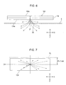
- FIGs. 6 and 7 illustrate a comparative example.
- a magnet 104 used in the comparative example is magnetized such that a facing surface 104a and a mounting surface 4b have different magnetic poles opposite to each other.
- magnetic lines of force in this magnetization radially extend from the centroid of the facing surface 104a, serving as the north pole, and converge to the centroid of the mounting surface 104b, serving as the south pole.
- the magnetic lines of force radially extending from the centroid of the facing surface 104a cause a change in detection output iv in the arrangement in which the sensor 21 of the position detecting unit 20 faced the offset line SL 3 mm offset in the Y direction from the center line of the magnet 104 in the width direction thereof to be more gradual than that in the embodiment in Fig. 12B .
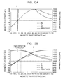
- Fig. 13A illustrates the intensities of magnetic field components acting on the sensor 21 in the comparative example in a state in which the sensor 21 of the position detecting unit 20 faced the center line Om of the magnet 104.
- the detection output iv from the differential amplifier 24 steeply changed when the magnet 104 passed the detection position b illustrated in Fig. 4B .
- the detection output iv from the differential amplifier 24 exhibits an extremely gradual change. Assuming that a change in resistance corresponding to the threshold value v is approximately 0.5%, an error included in the travel distance of the magnet 104 traveling while the threshold value changes from 0% to 1% to cause variation before the switch output vi is inverted is increased to approximately 0.7 mm.
- FIG. 12A and 12B A comparison between Figs. 12A and 12B and Figs. 13A and 13B demonstrates the following:
- the rotation detector 1 including the magnet 4 according to the embodiment illustrated in Figs. 4A and 4B , if both of the two position detecting units 20A and 20B are offset in the Y direction from the center line Om of the magnet 4, the positions of the position detecting units 20A and 20B can be easily adjusted so as to produce the switch output vi at the same time.
- the magnet 4 is rectangular and the side surfaces 4c, 4c along the long sides are oriented in the direction of the tangent to the revolution path ⁇ and the end surfaces 4d, 4d oriented in the rotating direction serve as the different magnetic poles, the influence of the magnetic field component in the Y direction on the sensors 21 can be reduced in the arrangement in which the sensors 21 face the offset line SL as illustrated in Fig. 5 .
- the magnetic field components radially extending from the centroid of the facing surface 104a tend to cause a time lag between the switch outputs vi from the two position detecting units 20A and 20B. It is difficult to position the two position detecting units 20A and 20B so that the units produce outputs at the same time.
Landscapes
- Physics & Mathematics (AREA)
- General Physics & Mathematics (AREA)
- Engineering & Computer Science (AREA)
- Transportation (AREA)
- Mechanical Engineering (AREA)
- Condensed Matter Physics & Semiconductors (AREA)
- Transmission And Conversion Of Sensor Element Output (AREA)
- Measurement Of Length, Angles, Or The Like Using Electric Or Magnetic Means (AREA)
Claims (5)
- Détecteur de rotation (1) comprenant :une unité tournante (2) ;un aimant (4) placé sur l'unité tournante ;une unité de détection d'angle (10) configurée pour détecter un changement d'angle de rotation de l'unité tournante en détectant un champ magnétique de fuite provenant de l'aimant ; etau moins une unité de détection de position (20A, 20B) configurée pour fonctionner quand l'aimant atteint une position prédéterminée,dans lequel l'aimant a deux surfaces d'extrémité (4d) qui sont éloignées d'un axe de rotation de l'unité tournante et qui sont orientées dans une direction de rotation et sont magnétisées avec des pôles magnétiques différents, et a une surface plate (4a) parallèle à un plan de rotation comprenant un chemin de rotation de l'unité tournante,dans lequel l'unité de détection d'angle est placée à l'écart d'un chemin de révolution de l'aimant dans une direction radiale du chemin de révolution, l'unité de détection d'angle comprend un élément à magnétorésistance (Rcl, Rc2, Rs1, Rs2) comprenant une couche magnétique libre, la direction dans laquelle la magnétisation de la couche magnétique libre varie est réglée pour être parallèle au plan de rotation, et l'élément à magnétorésistance inclus dans l'unité de détection d'angle peut être utilisé pour détecter un changement d'angle de rotation de l'unité tournante, etdans lequel ladite au moins une unité de détection de position est placée à l'écart de la surface plate de l'aimant dans une direction parallèle à l'axe de rotation de l'unité tournante et comprend un élément à magnétorésistance (Rx) et un circuit de commutation (23), l'élément à magnétorésistance inclus dans l'unité de détection de position a une résistance qui dépend de la variation d'intensité d'une composante de champ magnétique parallèle à la direction d'une tangente au chemin de révolution, la composante de champ magnétique est incluse dans un champ magnétique de fuite au voisinage de la surface plate de l'aimant, et le circuit de commutation est configuré pour produire une sortie de commutation basée sur une variation de la résistance.
- Détecteur de rotation selon la revendication 1,
dans lequel ladite au moins une unité de détection de position comprend une pluralité d'unités de détection de position, et
dans lequel les éléments à magnétorésistance inclus dans les unités de détection de position sont agencés de façon à être décalés dans la direction radiale depuis une ligne centrale qui divise une largeur de l'aimant en deux moitiés dans la direction radiale. - Détecteur de rotation selon la revendication 1 ou 2, dans lequel l'aimant est un aimant rectangulaire en forme de tige qui a des surfaces latérales le long de grands côtés et des surfaces d'extrémité le long de petits côtés et qui a une épaisseur régulière, les surfaces d'extrémité sont magnétisées avec des pôles magnétiques différents, et la direction longitudinale de l'aimant est orientée dans la direction de la tangente au chemin de révolution.
- Détecteur de rotation selon l'une quelconque des revendications 1 à 3, dans lequel ladite au moins une unité de détection de position comprend deux unités de détection de position et les unités de détection de position produisent simultanément des sorties de commutation quand l'unité tournante tourne d'un angle prédéterminé.
- Détecteur de rotation selon la revendication 4, dans lequel l'unité de détection d'angle détecte le degré d'actionnement d'une pédale de frein d'un véhicule à moteur, une des sorties de commutation des deux unités de détection de position est utilisée pour réaliser une commande pour allumer un feu de freinage, et l'autre des sorties de commutation est utilisée pour réaliser une commande pour libérer un régulateur de vitesse automatique.
Applications Claiming Priority (1)
| Application Number | Priority Date | Filing Date | Title |
|---|---|---|---|
| JP2013175240A JP6049570B2 (ja) | 2013-08-27 | 2013-08-27 | 回転検出装置 |
Publications (2)
| Publication Number | Publication Date |
|---|---|
| EP2843370A1 EP2843370A1 (fr) | 2015-03-04 |
| EP2843370B1 true EP2843370B1 (fr) | 2016-01-06 |
Family
ID=50439274
Family Applications (1)
| Application Number | Title | Priority Date | Filing Date |
|---|---|---|---|
| EP14163796.7A Active EP2843370B1 (fr) | 2013-08-27 | 2014-04-08 | Détecteur de rotation |
Country Status (4)
| Country | Link |
|---|---|
| US (1) | US9506738B2 (fr) |
| EP (1) | EP2843370B1 (fr) |
| JP (1) | JP6049570B2 (fr) |
| CN (1) | CN104422386B (fr) |
Families Citing this family (17)
| Publication number | Priority date | Publication date | Assignee | Title |
|---|---|---|---|---|
| JP6093562B2 (ja) * | 2012-12-07 | 2017-03-08 | 株式会社トランストロン | 変位検出装置 |
| JP6621253B2 (ja) * | 2015-06-23 | 2019-12-18 | キヤノン株式会社 | 撮像装置、制御方法およびプログラム |
| EP3182170B1 (fr) * | 2015-12-17 | 2023-09-27 | Mettler-Toledo Safeline Limited | Appareil de détection de métaux et procédé d'utilisation d'un appareil de détection de métaux |
| JP6512141B2 (ja) * | 2016-03-09 | 2019-05-15 | Tdk株式会社 | 磁石および変位検出装置 |
| EP4224714A1 (fr) | 2016-09-22 | 2023-08-09 | Solaredge Technologies Ltd. | Dispositifs de commutation pour un convertisseur de puissance |
| JP6723630B2 (ja) * | 2016-09-30 | 2020-07-15 | アルプスアルパイン株式会社 | 磁気検出装置 |
| JP6280610B1 (ja) * | 2016-10-03 | 2018-02-14 | Tdk株式会社 | 磁気抵抗効果素子及びその製造方法、並びに位置検出装置 |
| JP6787260B2 (ja) * | 2017-06-14 | 2020-11-18 | 株式会社デンソー | ポジションセンサ |
| EP3707475B1 (fr) * | 2017-11-09 | 2021-07-07 | Griessbach GmbH | Interrupteur doté d'un ensemble d'aimants |
| FR3082615B1 (fr) | 2018-06-15 | 2020-10-16 | Electricfil Automotive | Methode de determination d'une position angulaire relative entre deux pieces |
| FR3087256B1 (fr) | 2018-10-15 | 2020-10-30 | Electricfil Automotive | Methode et systeme capteur de determination d'une position angulaire relative entre deux pieces, et procede de fabrication d'un corps magnetique |
| TWI705232B (zh) * | 2018-10-28 | 2020-09-21 | 愛盛科技股份有限公司 | 角度感測裝置 |
| CN111102916A (zh) | 2018-10-28 | 2020-05-05 | 爱盛科技股份有限公司 | 角度感测装置 |
| CN113985328B (zh) * | 2021-12-24 | 2022-03-18 | 国网山东省电力公司沂源县供电公司 | 变电站用旋转式磁变量测量装置 |
| CN114216393B (zh) * | 2022-02-21 | 2022-05-17 | 泉州昆泰芯微电子科技有限公司 | 旋转角度检测装置、旋钮、学习用具及娱乐用具 |
| CN114825786A (zh) * | 2022-03-21 | 2022-07-29 | 福建盛海智能科技有限公司 | 一种非接触式小角度电机连续定位装置及方法 |
| DE102023101505A1 (de) | 2023-01-23 | 2024-07-25 | Infineon Technologies Ag | Vorrichtung und verfahren zum messen eines magnetwinkels |
Family Cites Families (19)
| Publication number | Priority date | Publication date | Assignee | Title |
|---|---|---|---|---|
| JPS6281502A (ja) * | 1985-10-04 | 1987-04-15 | Ngk Spark Plug Co Ltd | 回転角検出装置 |
| DE4014885C2 (de) * | 1989-05-13 | 1995-07-13 | Aisan Ind | Drehwinkelaufnehmer |
| DE19736454B4 (de) | 1997-08-21 | 2005-01-27 | Infineon Technologies Ag | Kontaktloser Näherungsschalter |
| JP4378814B2 (ja) * | 1999-07-16 | 2009-12-09 | 株式会社日本自動車部品総合研究所 | 回転角検出装置 |
| DE10008537A1 (de) * | 2000-02-24 | 2001-09-06 | Bosch Gmbh Robert | Messvorrichtung zur berührungslosen Erfassung eines Drehwinkels |
| US6330838B1 (en) * | 2000-05-11 | 2001-12-18 | Teleflex Incorporated | Pedal assembly with non-contact pedal position sensor for generating a control signal |
| US6498480B1 (en) * | 2000-11-22 | 2002-12-24 | Wabash Technologies, Inc. | Magnetic non-contacting rotary transducer |
| US6693424B2 (en) * | 2001-06-08 | 2004-02-17 | Denso Corporation | Magnetic rotation angle sensor |
| JP2005291387A (ja) * | 2004-03-31 | 2005-10-20 | Taiyo Ltd | 移動する磁気物体の検知方法および装置 |
| US7635975B2 (en) * | 2004-05-21 | 2009-12-22 | Kabushiki Kaisha Yaskawa Denki | Absolute multi-revolution encoder |
| FR2893410B1 (fr) | 2005-11-15 | 2008-12-05 | Moving Magnet Tech Mmt | Capteur de position angulaire magnetique pour une course allant jusqu'a 360 |
| JP4608464B2 (ja) * | 2006-06-30 | 2011-01-12 | 株式会社小松製作所 | 回動角センサ |
| JP4273363B2 (ja) * | 2006-11-21 | 2009-06-03 | 日立金属株式会社 | 回転角度検出装置、回転機、及び回転角度検出法 |
| JP2009063316A (ja) * | 2007-09-04 | 2009-03-26 | Tokai Rika Co Ltd | 回転角度検出装置及びシフト装置 |
| CN102317743A (zh) * | 2009-02-26 | 2012-01-11 | 阿尔卑斯电气株式会社 | 旋转检测装置 |
| US8587295B2 (en) * | 2009-02-26 | 2013-11-19 | Hitachi Metals, Ltd. | Angle detection apparatus and position detection apparatus |
| JP5156671B2 (ja) * | 2009-02-27 | 2013-03-06 | 株式会社日立製作所 | 磁界検出装置および計測装置 |
| JP5600528B2 (ja) * | 2010-09-03 | 2014-10-01 | 株式会社東海理化電機製作所 | 回転角度検出装置 |
| JP5840374B2 (ja) * | 2011-03-31 | 2016-01-06 | オリエンタルモーター株式会社 | アブソリュートエンコーダ装置及びモータ |
-
2013
- 2013-08-27 JP JP2013175240A patent/JP6049570B2/ja active Active
-
2014
- 2014-04-08 EP EP14163796.7A patent/EP2843370B1/fr active Active
- 2014-06-05 US US14/296,906 patent/US9506738B2/en active Active
- 2014-08-25 CN CN201410422967.9A patent/CN104422386B/zh active Active
Also Published As
| Publication number | Publication date |
|---|---|
| US9506738B2 (en) | 2016-11-29 |
| US20150061654A1 (en) | 2015-03-05 |
| JP6049570B2 (ja) | 2016-12-21 |
| CN104422386A (zh) | 2015-03-18 |
| EP2843370A1 (fr) | 2015-03-04 |
| CN104422386B (zh) | 2017-04-12 |
| JP2015045506A (ja) | 2015-03-12 |
Similar Documents
| Publication | Publication Date | Title |
|---|---|---|
| EP2843370B1 (fr) | Détecteur de rotation | |
| KR101721087B1 (ko) | 다중-주기 절대 위치 센서 | |
| US20140354270A1 (en) | Magnetic position detection device | |
| EP3767241A1 (fr) | Capteur de champ magnétique avec immunité contre les champs parasites et grandes performances d'entrefer | |
| EP2549236B1 (fr) | Capteurs magnétiques à réluctance variable avec aimant stationnaire | |
| US11099033B2 (en) | Position detection system | |
| JP5589458B2 (ja) | 回転角度・トルク検出装置 | |
| US20130293220A1 (en) | Methods and apparatus for magnetic sensors having highly uniform magnetic fields | |
| CN110196399A (zh) | 角传感器系统和杂散场消除方法 | |
| US12007294B2 (en) | Operation processing apparatus, angle sensor and power steering apparatus | |
| US20180313670A1 (en) | Magnetism-detecting device and moving-body-detecting device | |
| JP2014066561A (ja) | 回転角度・トルク検出装置 | |
| CN105424065A (zh) | 磁位置传感器和感测方法 | |
| CN110926506B (zh) | 角度传感器系统 | |
| JP2010527454A (ja) | 直線運動又は回転運動を非接触に検出するための装置 | |
| JP6455314B2 (ja) | 回転検出装置 | |
| KR100532795B1 (ko) | 물체의 위치를 무접촉 방식으로 검출하기 위한 장치 | |
| US9797963B2 (en) | Systems and methods for a magnetic target with magnetic bias field | |
| WO2019171763A1 (fr) | Capteur de position linéaire | |
| KR20160029989A (ko) | 토크 센서 장치 | |
| JP2006084416A (ja) | 移動体位置検出装置 | |
| JP2004037236A (ja) | 回転角度検出装置 | |
| JP2014065367A (ja) | 回転角度・トルク検出装置 | |
| CN111693909B (zh) | 用于确定旋转构件的至少一个旋转参数的系统 | |
| JP2011043398A (ja) | 回転トルク検出装置 |
Legal Events
| Date | Code | Title | Description |
|---|---|---|---|
| 17P | Request for examination filed |
Effective date: 20140408 |
|
| AK | Designated contracting states |
Kind code of ref document: A1 Designated state(s): AL AT BE BG CH CY CZ DE DK EE ES FI FR GB GR HR HU IE IS IT LI LT LU LV MC MK MT NL NO PL PT RO RS SE SI SK SM TR |
|
| AX | Request for extension of the european patent |
Extension state: BA ME |
|
| PUAI | Public reference made under article 153(3) epc to a published international application that has entered the european phase |
Free format text: ORIGINAL CODE: 0009012 |
|
| R17P | Request for examination filed (corrected) |
Effective date: 20150610 |
|
| RBV | Designated contracting states (corrected) |
Designated state(s): AL AT BE BG CH CY CZ DE DK EE ES FI FR GB GR HR HU IE IS IT LI LT LU LV MC MK MT NL NO PL PT RO RS SE SI SK SM TR |
|
| RIN1 | Information on inventor provided before grant (corrected) |
Inventor name: ONODERA, TAKASHI Inventor name: NOGUCHI, TAKAFUMI Inventor name: NAKAMURA, TOKUO |
|
| GRAP | Despatch of communication of intention to grant a patent |
Free format text: ORIGINAL CODE: EPIDOSNIGR1 |
|
| RIC1 | Information provided on ipc code assigned before grant |
Ipc: G01B 7/30 20060101ALI20150709BHEP Ipc: B60T 7/04 20060101ALI20150709BHEP Ipc: G01R 33/09 20060101ALI20150709BHEP Ipc: G01D 5/14 20060101AFI20150709BHEP |
|
| INTG | Intention to grant announced |
Effective date: 20150728 |
|
| RAP1 | Party data changed (applicant data changed or rights of an application transferred) |
Owner name: ALPS ELECTRIC CO., LTD. |
|
| GRAS | Grant fee paid |
Free format text: ORIGINAL CODE: EPIDOSNIGR3 |
|
| GRAA | (expected) grant |
Free format text: ORIGINAL CODE: 0009210 |
|
| AK | Designated contracting states |
Kind code of ref document: B1 Designated state(s): AL AT BE BG CH CY CZ DE DK EE ES FI FR GB GR HR HU IE IS IT LI LT LU LV MC MK MT NL NO PL PT RO RS SE SI SK SM TR |
|
| REG | Reference to a national code |
Ref country code: GB Ref legal event code: FG4D |
|
| REG | Reference to a national code |
Ref country code: CH Ref legal event code: EP |
|
| REG | Reference to a national code |
Ref country code: IE Ref legal event code: FG4D |
|
| REG | Reference to a national code |
Ref country code: AT Ref legal event code: REF Ref document number: 769221 Country of ref document: AT Kind code of ref document: T Effective date: 20160215 |
|
| REG | Reference to a national code |
Ref country code: DE Ref legal event code: R096 Ref document number: 602014000677 Country of ref document: DE |
|
| REG | Reference to a national code |
Ref country code: FR Ref legal event code: PLFP Year of fee payment: 3 |
|
| REG | Reference to a national code |
Ref country code: LT Ref legal event code: MG4D |
|
| REG | Reference to a national code |
Ref country code: NL Ref legal event code: MP Effective date: 20160106 |
|
| REG | Reference to a national code |
Ref country code: AT Ref legal event code: MK05 Ref document number: 769221 Country of ref document: AT Kind code of ref document: T Effective date: 20160106 |
|
| PG25 | Lapsed in a contracting state [announced via postgrant information from national office to epo] |
Ref country code: NL Free format text: LAPSE BECAUSE OF FAILURE TO SUBMIT A TRANSLATION OF THE DESCRIPTION OR TO PAY THE FEE WITHIN THE PRESCRIBED TIME-LIMIT Effective date: 20160106 |
|
| PG25 | Lapsed in a contracting state [announced via postgrant information from national office to epo] |
Ref country code: FI Free format text: LAPSE BECAUSE OF FAILURE TO SUBMIT A TRANSLATION OF THE DESCRIPTION OR TO PAY THE FEE WITHIN THE PRESCRIBED TIME-LIMIT Effective date: 20160106 Ref country code: NO Free format text: LAPSE BECAUSE OF FAILURE TO SUBMIT A TRANSLATION OF THE DESCRIPTION OR TO PAY THE FEE WITHIN THE PRESCRIBED TIME-LIMIT Effective date: 20160406 Ref country code: ES Free format text: LAPSE BECAUSE OF FAILURE TO SUBMIT A TRANSLATION OF THE DESCRIPTION OR TO PAY THE FEE WITHIN THE PRESCRIBED TIME-LIMIT Effective date: 20160106 Ref country code: GR Free format text: LAPSE BECAUSE OF FAILURE TO SUBMIT A TRANSLATION OF THE DESCRIPTION OR TO PAY THE FEE WITHIN THE PRESCRIBED TIME-LIMIT Effective date: 20160407 Ref country code: IT Free format text: LAPSE BECAUSE OF FAILURE TO SUBMIT A TRANSLATION OF THE DESCRIPTION OR TO PAY THE FEE WITHIN THE PRESCRIBED TIME-LIMIT Effective date: 20160106 Ref country code: HR Free format text: LAPSE BECAUSE OF FAILURE TO SUBMIT A TRANSLATION OF THE DESCRIPTION OR TO PAY THE FEE WITHIN THE PRESCRIBED TIME-LIMIT Effective date: 20160106 |
|
| PG25 | Lapsed in a contracting state [announced via postgrant information from national office to epo] |
Ref country code: PL Free format text: LAPSE BECAUSE OF FAILURE TO SUBMIT A TRANSLATION OF THE DESCRIPTION OR TO PAY THE FEE WITHIN THE PRESCRIBED TIME-LIMIT Effective date: 20160106 Ref country code: SE Free format text: LAPSE BECAUSE OF FAILURE TO SUBMIT A TRANSLATION OF THE DESCRIPTION OR TO PAY THE FEE WITHIN THE PRESCRIBED TIME-LIMIT Effective date: 20160106 Ref country code: AT Free format text: LAPSE BECAUSE OF FAILURE TO SUBMIT A TRANSLATION OF THE DESCRIPTION OR TO PAY THE FEE WITHIN THE PRESCRIBED TIME-LIMIT Effective date: 20160106 Ref country code: LT Free format text: LAPSE BECAUSE OF FAILURE TO SUBMIT A TRANSLATION OF THE DESCRIPTION OR TO PAY THE FEE WITHIN THE PRESCRIBED TIME-LIMIT Effective date: 20160106 Ref country code: PT Free format text: LAPSE BECAUSE OF FAILURE TO SUBMIT A TRANSLATION OF THE DESCRIPTION OR TO PAY THE FEE WITHIN THE PRESCRIBED TIME-LIMIT Effective date: 20160506 Ref country code: BE Free format text: LAPSE BECAUSE OF NON-PAYMENT OF DUE FEES Effective date: 20160430 Ref country code: RS Free format text: LAPSE BECAUSE OF FAILURE TO SUBMIT A TRANSLATION OF THE DESCRIPTION OR TO PAY THE FEE WITHIN THE PRESCRIBED TIME-LIMIT Effective date: 20160106 Ref country code: IS Free format text: LAPSE BECAUSE OF FAILURE TO SUBMIT A TRANSLATION OF THE DESCRIPTION OR TO PAY THE FEE WITHIN THE PRESCRIBED TIME-LIMIT Effective date: 20160506 Ref country code: LV Free format text: LAPSE BECAUSE OF FAILURE TO SUBMIT A TRANSLATION OF THE DESCRIPTION OR TO PAY THE FEE WITHIN THE PRESCRIBED TIME-LIMIT Effective date: 20160106 |
|
| REG | Reference to a national code |
Ref country code: DE Ref legal event code: R097 Ref document number: 602014000677 Country of ref document: DE |
|
| PG25 | Lapsed in a contracting state [announced via postgrant information from national office to epo] |
Ref country code: DK Free format text: LAPSE BECAUSE OF FAILURE TO SUBMIT A TRANSLATION OF THE DESCRIPTION OR TO PAY THE FEE WITHIN THE PRESCRIBED TIME-LIMIT Effective date: 20160106 Ref country code: EE Free format text: LAPSE BECAUSE OF FAILURE TO SUBMIT A TRANSLATION OF THE DESCRIPTION OR TO PAY THE FEE WITHIN THE PRESCRIBED TIME-LIMIT Effective date: 20160106 |
|
| PLBE | No opposition filed within time limit |
Free format text: ORIGINAL CODE: 0009261 |
|
| STAA | Information on the status of an ep patent application or granted ep patent |
Free format text: STATUS: NO OPPOSITION FILED WITHIN TIME LIMIT |
|
| PG25 | Lapsed in a contracting state [announced via postgrant information from national office to epo] |
Ref country code: CZ Free format text: LAPSE BECAUSE OF FAILURE TO SUBMIT A TRANSLATION OF THE DESCRIPTION OR TO PAY THE FEE WITHIN THE PRESCRIBED TIME-LIMIT Effective date: 20160106 Ref country code: SK Free format text: LAPSE BECAUSE OF FAILURE TO SUBMIT A TRANSLATION OF THE DESCRIPTION OR TO PAY THE FEE WITHIN THE PRESCRIBED TIME-LIMIT Effective date: 20160106 Ref country code: RO Free format text: LAPSE BECAUSE OF FAILURE TO SUBMIT A TRANSLATION OF THE DESCRIPTION OR TO PAY THE FEE WITHIN THE PRESCRIBED TIME-LIMIT Effective date: 20160106 Ref country code: SM Free format text: LAPSE BECAUSE OF FAILURE TO SUBMIT A TRANSLATION OF THE DESCRIPTION OR TO PAY THE FEE WITHIN THE PRESCRIBED TIME-LIMIT Effective date: 20160106 |
|
| 26N | No opposition filed |
Effective date: 20161007 |
|
| PG25 | Lapsed in a contracting state [announced via postgrant information from national office to epo] |
Ref country code: BE Free format text: LAPSE BECAUSE OF FAILURE TO SUBMIT A TRANSLATION OF THE DESCRIPTION OR TO PAY THE FEE WITHIN THE PRESCRIBED TIME-LIMIT Effective date: 20160106 Ref country code: LU Free format text: LAPSE BECAUSE OF FAILURE TO SUBMIT A TRANSLATION OF THE DESCRIPTION OR TO PAY THE FEE WITHIN THE PRESCRIBED TIME-LIMIT Effective date: 20160408 |
|
| REG | Reference to a national code |
Ref country code: IE Ref legal event code: MM4A |
|
| PG25 | Lapsed in a contracting state [announced via postgrant information from national office to epo] |
Ref country code: BG Free format text: LAPSE BECAUSE OF FAILURE TO SUBMIT A TRANSLATION OF THE DESCRIPTION OR TO PAY THE FEE WITHIN THE PRESCRIBED TIME-LIMIT Effective date: 20160406 Ref country code: SI Free format text: LAPSE BECAUSE OF FAILURE TO SUBMIT A TRANSLATION OF THE DESCRIPTION OR TO PAY THE FEE WITHIN THE PRESCRIBED TIME-LIMIT Effective date: 20160106 |
|
| REG | Reference to a national code |
Ref country code: FR Ref legal event code: PLFP Year of fee payment: 4 |
|
| PG25 | Lapsed in a contracting state [announced via postgrant information from national office to epo] |
Ref country code: IE Free format text: LAPSE BECAUSE OF NON-PAYMENT OF DUE FEES Effective date: 20160408 |
|
| REG | Reference to a national code |
Ref country code: DE Ref legal event code: R082 Ref document number: 602014000677 Country of ref document: DE Representative=s name: SCHMITT-NILSON SCHRAUD WAIBEL WOHLFROM PATENTA, DE |
|
| REG | Reference to a national code |
Ref country code: CH Ref legal event code: PL |
|
| PG25 | Lapsed in a contracting state [announced via postgrant information from national office to epo] |
Ref country code: LI Free format text: LAPSE BECAUSE OF NON-PAYMENT OF DUE FEES Effective date: 20170430 Ref country code: CH Free format text: LAPSE BECAUSE OF NON-PAYMENT OF DUE FEES Effective date: 20170430 |
|
| REG | Reference to a national code |
Ref country code: FR Ref legal event code: PLFP Year of fee payment: 5 |
|
| PG25 | Lapsed in a contracting state [announced via postgrant information from national office to epo] |
Ref country code: HU Free format text: LAPSE BECAUSE OF FAILURE TO SUBMIT A TRANSLATION OF THE DESCRIPTION OR TO PAY THE FEE WITHIN THE PRESCRIBED TIME-LIMIT; INVALID AB INITIO Effective date: 20140408 |
|
| PG25 | Lapsed in a contracting state [announced via postgrant information from national office to epo] |
Ref country code: MT Free format text: LAPSE BECAUSE OF NON-PAYMENT OF DUE FEES Effective date: 20160430 Ref country code: MC Free format text: LAPSE BECAUSE OF FAILURE TO SUBMIT A TRANSLATION OF THE DESCRIPTION OR TO PAY THE FEE WITHIN THE PRESCRIBED TIME-LIMIT Effective date: 20160106 Ref country code: MK Free format text: LAPSE BECAUSE OF FAILURE TO SUBMIT A TRANSLATION OF THE DESCRIPTION OR TO PAY THE FEE WITHIN THE PRESCRIBED TIME-LIMIT Effective date: 20160106 Ref country code: CY Free format text: LAPSE BECAUSE OF FAILURE TO SUBMIT A TRANSLATION OF THE DESCRIPTION OR TO PAY THE FEE WITHIN THE PRESCRIBED TIME-LIMIT Effective date: 20160106 |
|
| PG25 | Lapsed in a contracting state [announced via postgrant information from national office to epo] |
Ref country code: TR Free format text: LAPSE BECAUSE OF FAILURE TO SUBMIT A TRANSLATION OF THE DESCRIPTION OR TO PAY THE FEE WITHIN THE PRESCRIBED TIME-LIMIT Effective date: 20160106 Ref country code: AL Free format text: LAPSE BECAUSE OF FAILURE TO SUBMIT A TRANSLATION OF THE DESCRIPTION OR TO PAY THE FEE WITHIN THE PRESCRIBED TIME-LIMIT Effective date: 20160106 |
|
| REG | Reference to a national code |
Ref country code: DE Ref legal event code: R082 Ref document number: 602014000677 Country of ref document: DE Representative=s name: SCHMITT-NILSON SCHRAUD WAIBEL WOHLFROM PATENTA, DE Ref country code: DE Ref legal event code: R081 Ref document number: 602014000677 Country of ref document: DE Owner name: ALPS ALPINE CO., LTD., JP Free format text: FORMER OWNER: ALPS ELECTRIC CO., LTD., TOKIO/TOKYO, JP |
|
| PGFP | Annual fee paid to national office [announced via postgrant information from national office to epo] |
Ref country code: FR Payment date: 20200420 Year of fee payment: 7 |
|
| PGFP | Annual fee paid to national office [announced via postgrant information from national office to epo] |
Ref country code: GB Payment date: 20200427 Year of fee payment: 7 |
|
| GBPC | Gb: european patent ceased through non-payment of renewal fee |
Effective date: 20210408 |
|
| PG25 | Lapsed in a contracting state [announced via postgrant information from national office to epo] |
Ref country code: GB Free format text: LAPSE BECAUSE OF NON-PAYMENT OF DUE FEES Effective date: 20210408 Ref country code: FR Free format text: LAPSE BECAUSE OF NON-PAYMENT OF DUE FEES Effective date: 20210430 |
|
| PGFP | Annual fee paid to national office [announced via postgrant information from national office to epo] |
Ref country code: DE Payment date: 20250422 Year of fee payment: 12 |