EP2843449B1 - Mehradriges glasfaserübertragungssystem - Google Patents
Mehradriges glasfaserübertragungssystem Download PDFInfo
- Publication number
- EP2843449B1 EP2843449B1 EP13781468.7A EP13781468A EP2843449B1 EP 2843449 B1 EP2843449 B1 EP 2843449B1 EP 13781468 A EP13781468 A EP 13781468A EP 2843449 B1 EP2843449 B1 EP 2843449B1
- Authority
- EP
- European Patent Office
- Prior art keywords
- less
- optical fiber
- core
- cores
- core optical
- Prior art date
- Legal status (The legal status is an assumption and is not a legal conclusion. Google has not performed a legal analysis and makes no representation as to the accuracy of the status listed.)
- Active
Links
Images




Classifications
-
- G—PHYSICS
- G02—OPTICS
- G02B—OPTICAL ELEMENTS, SYSTEMS OR APPARATUS
- G02B6/00—Light guides; Structural details of arrangements comprising light guides and other optical elements, e.g. couplings
- G02B6/02—Optical fibres with cladding with or without a coating
- G02B6/02042—Multicore optical fibres
-
- G—PHYSICS
- G02—OPTICS
- G02B—OPTICAL ELEMENTS, SYSTEMS OR APPARATUS
- G02B6/00—Light guides; Structural details of arrangements comprising light guides and other optical elements, e.g. couplings
- G02B6/44—Mechanical structures for providing tensile strength and external protection for fibres, e.g. optical transmission cables
- G02B6/4401—Optical cables
- G02B6/441—Optical cables built up from sub-bundles
- G02B6/4413—Helical structure
-
- G—PHYSICS
- G02—OPTICS
- G02B—OPTICAL ELEMENTS, SYSTEMS OR APPARATUS
- G02B6/00—Light guides; Structural details of arrangements comprising light guides and other optical elements, e.g. couplings
- G02B6/44—Mechanical structures for providing tensile strength and external protection for fibres, e.g. optical transmission cables
- G02B6/4401—Optical cables
Definitions
- Non Patent Literature 1 shows that in an uncoupled multi-core optical fiber in which interference between signals is suppressed by reducing crosstalk between cores, the magnitude (statistical average) of crosstalk is independent of at least the twist of the optical fiber.
- Non Patent Literature 2 shows the simulation result indicative of a possibility of a significant reduction in inter-core crosstalk in an uncoupled multi-core optical fiber when the twist rate per unit length is precisely controlled and the fiber is twisted at a constant short pitch of about 100 rotations/m.
- Non Patent Literature 3 describes the technique of transmitting signals by means of a coupled multi-core optical fiber (multi-core optical fiber with high crosstalk between cores) and demultiplexing and decoding signals of respective cores mixed because of crosstalk, by the MIMO technology.
- the present invention has been accomplished in order to solve the above-described problem and it is an object of the present invention to provide a multi-core optical fiber, a multi-core optical fiber cable, and a multi-core optical fiber transmission system enabling calculation effectively using the MIMO technology.
- a fourth aspect, not forming part of the claimed invention, applicable to at least any one of the first to third aspects is preferably the multi-core optical fiber wherein in the state in which the multi-core optical fiber is wound on the bobbin with the radius R bobbin (m), the aforementioned Expression (2) is not more than 1.58 ⁇ 10 -13 ⁇ 0.2/R bobbin (s/m 1/2 ).
- a fifth aspect, not forming part of the claimed invention, applicable to at least any one of the first to fourth aspects is preferably the multi-core optical fiber wherein the in-use bending radius R is not less than 1 m.
- a sixth aspect, not forming part of the claimed invention, applicable to at least any one of the first to fifth aspects is preferably the multi-core optical fiber wherein the in-use bending radius R is not less than 0.2 m.
- the multi-core optical fiber may comprise a plurality of core groups composed of the plurality of cores, and in this configuration wherein the core groups are arranged, the core groups are adequately separated from each other so that crosstalk between the core groups is not more than - 15 dB.
- An eighth aspect, not forming part of the claimed invention, applicable to at least any one of the first to seventh aspects is preferably the multi-core optical fiber wherein when the plurality of cores constitute a plurality of core groups, the cores belonging to all the core groups are arranged on the circumference of any one of a plurality of concentric circles.
- the multi-core optical fiber is embedded while maintaining a state in which Expression (3) below is not more than 7.91x10 -12 (s/m 1/2 ) where an average twist rate defined as an average value along the longitudinal direction of the multi-core optical fiber of absolute values of angles of rotations of the cores per unit length, of the multi-core optical fiber is ⁇ (rad/m), where the shortest distance between centers of the respective cores is ⁇ (m), where a group index for a fundamental mode in each of the cores is n g , where an in-use bending radius defined as a bending radius in use of the multi-core optical fiber is R (m), where the speed of light in vacuum is c (m/s), and where the ratio of the circumference of a circle to its diameter is ⁇ . 2 n g ⁇ cR ⁇
- a twelfth aspect, not forming part of the claimed invention, applicable to at least any one of the ninth to eleventh aspects is preferably the multi-core optical fiber cable wherein the shortest distance ⁇ is not more than 25 ⁇ 10 -6 m.
- a thirteenth aspect, not forming part of the claimed invention, applicable to at least any one of the ninth to twelfth aspects is preferably the multi-core optical fiber cable wherein crosstalk between closest adjacent cores out of the plurality of cores is not less than - 15 dB.
- a multi-core optical fiber transmission system uses as a transmission line a multi-core optical fiber comprising: a plurality of cores each extending along a predetermined axis and arranged on a cross section perpendicular to the predetermined axis; and a cladding region integrally surrounding each of the cores.
- the number of taps N tap in execution of a spatially demultiplexing calculation by the MIMO technology is set to satisfy a relation defined by Expression (4) below where an average twist rate defined as an average value along the longitudinal direction of the multi-core optical fiber of absolute values of angles of rotations of the cores per unit length, of the multi-core optical fiber is ⁇ (rad/m), where the shortest distance between centers of the respective cores is ⁇ (m), when a group index for a fundamental mode in each of the cores is n g , where a longitudinal average defined as an average of bending radii along the longitudinal direction, of the multi-core optical fiber is R (m), where the speed of light in vacuum is c (m/s), where the ratio of the circumference of a circle to its diameter is ⁇ , and where a symbol rate of signal modulation is f symbol (Baud).
- a fifteenth aspect applicable to the fourteen aspect is preferably the multi-core optical fiber transmission system wherein the shortest distance ⁇ is not more than 25 ⁇ 10 -6 m.
- a sixteenth aspect may use the multi-core optical fiber according to at least any one of the first to eighth aspects as a transmission line.
- the multi-core optical fiber transmission system according to the sixteenth aspect is preferably one wherein where a fiber link length between a transmitter and a receiver is L (m) and where a symbol rate of signal modulation is f symbol (Baud), the number of taps N tap in execution of a spatially demultiplexing calculation by the MIMO technology is set to satisfy a relation defined by Expression (5) below. 8 ⁇ 1.58 ⁇ 10 ⁇ 13 L ⁇ N tap f symbol ⁇ 12 ⁇ 1.58 ⁇ 10 ⁇ 13 L
- a seventeenth aspect may use the multi-core optical fiber cable according to at least any one of the ninth to thirteenth aspects as a transmission line.
- the multi-core optical fiber transmission system according to the seventeenth aspect is preferably one wherein where a fiber link length between a transmitter and a receiver is L (m) and where a symbol rate of signal modulation is f symbol (Baud), the number of taps N tap in execution of a spatially demultiplexing calculation by the MIMO technology is set to satisfy a relation defined by Expression (6) below. 8 ⁇ 1.58 ⁇ 10 ⁇ 13 L ⁇ N tap f symbol ⁇ 12 ⁇ 1.58 ⁇ 10 ⁇ 13 L
- an eighteenth aspect applicable to at least any one of the fourteenth to seventeenth aspects is preferably the multi-core optical fiber transmission system wherein crosstalk between closest adjacent cores out of the plurality of cores is not less than - 15 dB.
- the computational complexity is proportional to the square of M.
- the number of channels M in the optical fiber is the product of the number of spatial modes and the number of polarization modes.
- MCF multi-core optical fiber
- the number of channels M is twice the number of cores.
- FIR finite impulse response
- N+1 is generally called the number of taps N tap and the smaller the number of taps, the smaller the computational complexity. If the DGD is small, spread of received signals on the time axis will become small, so as to decrease the number of taps. When a symbol rate (the number of modulation symbols per unit time) is small, the number of signal samplings per unit time is small even with constant spread of received signals on the time axis and thus the number of taps can be decreased. However, the symbol rate is preferably set as large as possible, in order to increase the speed of transmitted signals.
- the DGD between spatial modes is thus desirably as small as possible, in execution of the calculation using the MIMO technology and there are some techniques for reduction of DGD, reported as to the optical fibers of several modes.
- the DGD between supermodes in a coupled multi-core optical fiber can be reduced by enhancing confinement of light in each core or by increasing the core pitch.
- the DGD between spatial modes of individual cores does not have been so much investigated heretofore and it was not clear yet how the spin or twist of optical fiber affected the inter-core DGD, either.
- Non Patent Literature 1 bending of a fiber leads to very small differences between bending radii of respective cores depending on positions of the cores in the fiber and, therefore, it also leads to differences of optical paths of the respective cores.
- the equivalent refractive index is obtained by multiplying an actual refractive index by (1+x/R).
- the parameter R herein is a bending radius of a core as a reference, and x an amount of deviation from the reference core in the direction of bending radius. Therefore, each core in the MCF can have different equivalent refractive indices depending on bending and twisting of the MCF.
- Non Patent Literature 2 Since it is found according to Non Patent Literature 2 that the crosstalk between core m and core n in the MCF, or exchange of power mostly occurs at phase matching points where the equivalent refractive indices of core m and core n are equal, the crosstalk in the MCF can be modeled as exchange of power between cores discretely occurring at the phase matching points only.
- ⁇ stands for a distance (core pitch) between the center of core m and the center of core n, and ⁇ for an angle (rad) relative to the bending radius direction of position on a cross section of the MCF, of "core m" as viewed from the "midpoint between core m and core n.”
- ⁇ was constant, but ⁇ can also be assumed to be an average in the fiber longitudinal direction of absolute values of numbers of rotations per fiber length. Since ⁇ ⁇ can be considered to be a root-mean-square of inter-core DGD herein, it is understood that, in order to decrease the inter-core DGD, it is preferable that the core pitch ⁇ be as small as possible, the bending radius R of the fiber be as large as possible, and the twist rate ⁇ of the fiber be as large as possible.
- ⁇ is preferably the short core pitch of not more than 25 ⁇ m
- ⁇ is more preferably the short core pitch of not more than 20 ⁇ m
- ⁇ is still more preferably the short core pitch of not more than 15 ⁇ m
- ⁇ is yet more preferably the short core pitch of not more than 10 ⁇ m.
- the number of taps needs to be set so as to cover the time of not less than 4 ⁇ ⁇ on the time axis. Furthermore, in order to reflect the power of 99.74% or more of the original signals on the MIMO calculation, the number of taps needs to be set so as to cover the time of not less than 6 ⁇ ⁇ on the time axis.
- the number of taps needs to be set to not less than 8 ⁇ ⁇ f symbol , in order to reflect the power of 95.44% or more of the original signals on the MIMO calculation; the number of taps needs to be set to not less than 12 ⁇ ⁇ f symbol on the time axis, in order to reflect the power of 99.74% or more of the original signals on the MIMO calculation.
- Table 1 N tap To reflect power of 95.44% or more of original signals on MIMO calculation To reflect power of 99.74% or more of original signals on MIMO calculation 500 or less 2.5 ⁇ 10 -9 or less 1.67 ⁇ 10 -9 or less 450 or less 2.25 ⁇ 10 -9 or less 1.5 ⁇ 10 -9 or less 400 or less 2.0 ⁇ 10 -9 or less 1.33 ⁇ 10 -9 or less 350 or less 1.75 ⁇ 10 -9 or less 1.17 ⁇ 10 -9 or less 300 or less 1.5 ⁇ 1 -9 or less 1.0 ⁇ 10 -9 or less 250 or less 1.25 ⁇ 10 -9 or less 8.33 ⁇ 10 -10 or less 200 or less 1.0 ⁇ 10 -9 or less 6.67 ⁇ 10 -10 or less 150 or less 7.5 ⁇ 10 -10 or less 5.0 ⁇ 10 -10 or less 100 or less 5.0 ⁇ 10 -16 or less 3.33 ⁇ 10 -10 or less 50 or less 2.5 ⁇ 10 -10 or less 1.67 ⁇ 10 -10 or less
- the MCF When a desired transmission distance is given by L, the MCF preferably satisfies Expression (26) below, in order to reflect the power of 95.44% or more of the original signals on the MIMO calculation, and the MCF more preferably satisfies Expression (27) below, in order to reflect the power of 99.74% or more of the original signals on the MIMO calculation.
- Table 3 shows the results of calculations using Expressions (19) and (20).
- the MCF is preferably embedded in a cable so as to have appropriate values of ⁇ and ⁇ and maintain appropriate R, so that 2n g ⁇ /(cR)•( ⁇ ) -1/2 satisfies the values in Table 2 or Table 3.
- Table 6 N tap To reflect power of 95.44% or more of original signals on MIMO calculation To reflect power of 99.74% or more of original signals on MIMO calculation 500 or less 7.91 ⁇ 10 -12 or less 5.27 ⁇ 10 -12 or less 450 or less 7.12 ⁇ 10 -12 or less 4.74 ⁇ 10 -12 or less 400 or less 6.32 ⁇ 10 -12 or less 4.22 ⁇ 10 -12 or less 350 or less 5.53 ⁇ 10 -12 or less 3.69 ⁇ 10 -12 or less 300 or less 4.74 ⁇ 10 -12 or less 3.16 ⁇ 10 -12 or less 250 or less 3.95 ⁇ 10 -12 or less 2.64 ⁇ 10 -12 or less 200 or less 3.16 ⁇ 10 -12 or less 2.11 ⁇ 10 -12 or less 150 or less 2.37 ⁇ 10 -12 or less 1.58 ⁇ 10 -12 or less 100 or less 1.58 ⁇ 10 -12 or less 1.05 ⁇ 10 -12 or less 50 or less 7.91 ⁇ 10 -13 or less 5.27 ⁇ 10 -13 10 -13 or less Table 7 N tap To reflect power of 95.44% or more of original signals on MIMO calculation To reflect power
- ⁇ ⁇ /L 1/2 is more preferably controlled to not more than a value equivalent to PMD in a standard single-mode fiber (SSMF) or at least to not more than ten times the value because an increase of the number of taps can be controlled to not more than ten times.
- the PMD of SSMF is generally at most 0.5 ps/km 1/2 (i.e., about 1.58 ⁇ 10 -14 s/m 1/2 ) or less.
- the multi-core optical fiber of the present invention preferably satisfies Expression (28) below, based on above Expression (21).
- the multi-core optical fiber of the present invention preferably satisfies Expression (29) below.
- the multi-core optical fiber of the present invention preferably satisfies Expression (30) below.
- the multi-core optical fiber of the present invention preferably satisfies Expression (31) below.
- the units of the respective parameters are L (m), ⁇ (m), c (m/s), R (m), and ⁇ (rad/m).
- Table 10 shows values of 2n g ⁇ /(cR)•( ⁇ ) -1/2 desired to be satisfied by the multi-core optical fiber of the present invention, in order to satisfy Expressions (28) to (31), where the bending radius R of the MCF in use of the MCF after embedded in a cable and laid is assumed to be 10 m or more, 5 m or more, 3 m or more, 2 m or more, 1 m or more, and 0.2 m or more.
- the fiber When R stands for the bending radius of the fiber in use and R bobbin for the bending radius of the fiber in a wound state on a bobbin, the fiber preferably satisfies Expression (32) on the basis of Expression (21), for ⁇ ⁇ /L 1/2 to satisfy target A in use.
- N tap and f symbol preferably satisfy Expression (22) to reflect the power of 95.44% of the original signals on the MIMO calculation; N tap and f symbol more preferably satisfy Expression (23) to reflect the power of 99.74% of the original signals on the MIMO calculation; however, reflection of the power of a percentage of more than necessary will lead to increase in N tap and, in turn, to increase in computational complexity.
- N tap 12 f symbol ⁇ ⁇ ⁇ ⁇ N tap 8 f symbol
- N tap 12 f symbol ⁇ 2 n g ⁇ cR L ⁇ ⁇ N tap 8 f symbol
- the relation between N tap and f symbol preferably satisfies at least Expression (37) below on the basis of Expression (36).
- the unit of f symbol is Baud and the unit of L is m. 8 ⁇ 1.58 ⁇ 10 ⁇ 13 L ⁇ N tap f symbol ⁇ 12 ⁇ 1.58 ⁇ 10 ⁇ 13 L
- a multi-core optical fiber that can be used in an embodiment of the present invention preferably has a constellation in which a plurality of cores are arranged in physical proximity and in an optically coupled state to each other.
- Fig. 4 shows an example of sectional view of such a multi-core optical fiber.
- a plurality of cores 10 are arranged in proximity and a cladding 20 is disposed around them.
- the plurality of cores 10 may be in physical contact with each other, but they are preferably separated from each other without contact, so as to facilitate input/output of signals into and from the respective cores 10.
- the peripheries of the respective cores 10 are preferably separated at least about 1 ⁇ m or more from each other, more preferably separated at least about 5 ⁇ m or more from each other, and still more preferably separated at least about 10 ⁇ m or more from each other.
- the optically coupled state refers to a state in which the inter-core crosstalk is sufficiently large.
- the crosstalk between adjacent cores is preferably not less than - 15 dB, more preferably not less than - 10 dB, still more preferably not less than - 5 dB, and yet more preferably approximately 0 dB.
- the values listed as ⁇ heretofore are preferably at least "the shortest distances between the centers of the respective cores" and more preferably “the longest distances between the centers of the respective cores in physical proximity and in the optically coupled state.”
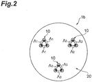
- a preferred multi-core optical fiber that can be used in an embodiment of the present invention is one wherein a plurality of embedded cores constitute a plurality of core groups each of which is composed of some cores, not all the cores, in physical proximity and in the optically coupled state, out of all the cores, and wherein the core groups are arranged in a state in which the crosstalk between them is appropriately suppressed.
- the crosstalk between adjacent cores in each core group is preferably not less than - 15 dB, more preferably not less than - 10 dB, still more preferably not less than - 5 dB, and yet more preferably approximately 0 dB.
- the crosstalk between core groups is preferably at least not more than - 16.7 dB, more preferably not more than - 20 dB, and still more preferably not more than - 30 dB.
- Fig. 5 shows an example of sectional view of such a multi-core optical fiber.
- the multi-core optical fiber 2 shown in Fig. 5 has a constellation in which seven core groups 11 each consisting of seven cores 10 are formed and these are covered by a cladding 20. It should be noted that these numbers are not limited to the exemplified values.
- the example of Fig. 4 can also be referred to as a constellation with one core group (cf. Fig. 1A ). Use of such MCF as a transmission line is preferred to reduce the computational complexity of the MIMO calculation in the case where the MIMO technology is applied individually to demulplexing and decoding of spatial multiplexed signals in each individual core group 11 but is not applied to all the cores together.
- a multi-core optical fiber transmission system using a multi-core optical fiber according to an embodiment of the present invention as a transmission line can decrease the DGD between spatial modes used in multiplexing, not by multiplexing signals in a plurality of supermodes guided together by the foregoing core groups 11 (i.e., not by coupling signals for spatial multiplexing of a transmitter to respective supermodes guided in the core groups of the MCF at time of coupling from the transmitter to the multi-core optical fiber and by spatially demultiplexing signals before the MIMO process of a receiver from the respective supermodes of the MCF at time of coupling from the multi-core optical fiber to the receiver), but by multiplexing signals in spatial modes guided in the respective cores 10 in the foregoing core groups 11 (i.e., by coupling the signals for spatial multiplexing of the transmitter to spatial modes individually guided in the respective cores of the multi-core optical fiber at time of coupling from the transmitter to the MCF and by spatially demultiplexing the signals before the MIMO process of the receiver from the respective
- Each of cores embedded in a multi-core optical fiber that can be used in an embodiment of the present invention preferably operates in a single mode. It is because this configuration can suppress occurrence of inter-mode DGD (i.e., DMD) in the same core.
- DGD inter-mode DGD
- each of the cores in the core group composed of the cores in physical proximity and in the optically coupled state operates in a single mode
- a core group guides spatial modes of up to the same order as the number of cores in the core group but spatial modes of orders larger than it are cut off.”
- each of cores embedded in an MCF that can be used in to an embodiment of the present invention preferably guides a plurality of spatial modes.
- a multi-core optical fiber according to an embodiment of the present invention is arranged so that each of the embedded cores guides a plurality of spatial modes, whereby random mode coupling between core modes of the same order in different cores or between core modes of different orders can occur at each of phase matching points.
- the multi-core optical fiber according to the present embodiment can achieve a high spatial mode density and a low DGD together.
- the DMD is preferably sufficiently small.
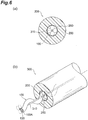
- FIGs. 6A and 6B show an example of the cabling.
- An optical fiber cable (multi-core optical fiber cable) 300 shown in Figs. 6A and 6B has a central member 310, a plurality of optical fibers 100 wound at a predetermined pitch on the central member 310, a hold wrap 250 wound on the optical fibers so as to maintain the wound state thereof, and a jacket 200 covering the periphery of the hold wrap 250.
- the optical fiber cable 300 is also applicable to the transmission line of the multi-core optical fiber transmission system shown in Fig. 1C .
- the aforementioned multi-core optical fibers 1, 2 are also applicable to the transmission line of the multi-core optical fiber transmission system shown in Fig. 1C .
- Each optical fiber 100 consists of a multi-core optical fiber 100A and a resin coating 130 entirely covering the multi-core optical fiber 100A.
- Each of the optical fibers 100 is wound at the predetermined pitch along the longitudinal direction thereof on the central member 310 so that it is bent in a constant radius of curvature.
- the jacket 200 covers the whole of the hold wrap 250 so as to protect the optical fibers 100 from external force.
- Fig. 6B shows only one fiber of the optical fibers 100 for simplicity of illustration, all the optical fibers 100 in the optical fiber cable 300 are wound on the central member 310 in fact.
- the bending radius R of the MCF can be controlled by adjusting the radius r h and pitch L p of the helix.
- Fig. 7 shows a relation between the radius r h and pitch L p of the helix.
- the multi-core optical fibers, multi-core optical fiber cables, and multi-core optical fiber transmission systems according to the embodiments of the present invention enable the calculation effectively using the MIMO technology. It should be noted that the present invention can be modified in various ways without having to be limited to the above embodiments.
- MMF multi-core optical fiber
- 10 ... core
- 11 ... core group
- 20 ... cladding
- 300 optical fiber able.
Landscapes
- Physics & Mathematics (AREA)
- General Physics & Mathematics (AREA)
- Optics & Photonics (AREA)
- Optical Communication System (AREA)
- Optical Fibers, Optical Fiber Cores, And Optical Fiber Bundles (AREA)
- Light Guides In General And Applications Therefor (AREA)
Claims (3)
- Vieladriges Lichtwellenleiter-Übertragungssystem, das als Übertragungsleitung einen vieladrigen Lichtwellenleiter verwendet, wobei es Folgendes umfasst: eine Vielzahl von Adern, die sich jeweils entlang einer vorbestimmten Achse erstrecken und auf einem Querschnitt, senkrecht zu der vorbestimmten Achse, angeordnet sind, und einen Mantelbereich, der integral jede der Adern umgibt,
wobei, wenn eine mittlere Verdrillungsrate, definiert als ein mittlerer Wert von absoluten Werten von Winkeln von Umdrehungen der Adern je Längeneinheit entlang einer Längsrichtung des vieladrigen Lichtwellenleiters, γ (rad/m) ist, der kürzeste Abstand zwischen Mitten der jeweiligen Adern Λ (m) ist, ein Gruppenindex für einen Grundmodus in jeder der Adern ng ist, ein Längsmittelwert, definiert als ein Mittelwert von Biegungsradien entlang der Längsrichtung, des vieladrigen Lichtwellenleiters R (m) ist, die Lichtgeschwindigkeit im Vakuum c (m/s) ist, das Verhältnis des Umfangs eines Kreises zu seinem Durchmesser π ist, dadurch gekennzeichnet, dass eine Symbolrate der Signalmodulation Fsymbol (Baud) ist,
die Anzahl von Abzweigen Ntap in Ausführung einer räumlich demultiplexierenden Berechnung durch die MIMO-Technologie so festgesetzt ist, dass sie eine Beziehung erfüllt, die durch den Ausdruck unten definiert wird:
- Vieladriges Lichtwellenleiter-Übertragungssystem nach Anspruch 1, wobei der kürzeste Abstand A nicht mehr als 25 × 10-6 m beträgt.
- Vieladriges Lichtwellenleiter-Übertragungssystem nach einem der Ansprüche 1 bis 2, wobei ein Übersprechen zwischen am engsten benachbarten Adern der Vielzhal von Adern nicht weniger als -15 dB beträgt.
Priority Applications (2)
| Application Number | Priority Date | Filing Date | Title |
|---|---|---|---|
| EP16192554.0A EP3144709B1 (de) | 2012-04-26 | 2013-04-23 | Mehradrige glasfaser, mehradriges glasfaserkabel und übertragungssystem mit mehradriger glasfaser |
| DK16192554.0T DK3144709T3 (da) | 2012-04-26 | 2013-04-23 | Flerkernet optisk fiber, flerkernet optisk fiberkabel og flerkernet optisk fiberoverførselssystem |
Applications Claiming Priority (2)
| Application Number | Priority Date | Filing Date | Title |
|---|---|---|---|
| JP2012101254 | 2012-04-26 | ||
| PCT/JP2013/061940 WO2013161825A1 (ja) | 2012-04-26 | 2013-04-23 | マルチコア光ファイバ、マルチコア光ファイバケーブル、および、マルチコア光ファイバ伝送システム |
Related Child Applications (2)
| Application Number | Title | Priority Date | Filing Date |
|---|---|---|---|
| EP16192554.0A Division EP3144709B1 (de) | 2012-04-26 | 2013-04-23 | Mehradrige glasfaser, mehradriges glasfaserkabel und übertragungssystem mit mehradriger glasfaser |
| EP16192554.0A Division-Into EP3144709B1 (de) | 2012-04-26 | 2013-04-23 | Mehradrige glasfaser, mehradriges glasfaserkabel und übertragungssystem mit mehradriger glasfaser |
Publications (3)
| Publication Number | Publication Date |
|---|---|
| EP2843449A1 EP2843449A1 (de) | 2015-03-04 |
| EP2843449A4 EP2843449A4 (de) | 2016-03-23 |
| EP2843449B1 true EP2843449B1 (de) | 2019-03-27 |
Family
ID=49483134
Family Applications (2)
| Application Number | Title | Priority Date | Filing Date |
|---|---|---|---|
| EP13781468.7A Active EP2843449B1 (de) | 2012-04-26 | 2013-04-23 | Mehradriges glasfaserübertragungssystem |
| EP16192554.0A Active EP3144709B1 (de) | 2012-04-26 | 2013-04-23 | Mehradrige glasfaser, mehradriges glasfaserkabel und übertragungssystem mit mehradriger glasfaser |
Family Applications After (1)
| Application Number | Title | Priority Date | Filing Date |
|---|---|---|---|
| EP16192554.0A Active EP3144709B1 (de) | 2012-04-26 | 2013-04-23 | Mehradrige glasfaser, mehradriges glasfaserkabel und übertragungssystem mit mehradriger glasfaser |
Country Status (6)
| Country | Link |
|---|---|
| US (1) | US9031368B2 (de) |
| EP (2) | EP2843449B1 (de) |
| JP (2) | JP6183357B2 (de) |
| CN (1) | CN104321673B (de) |
| DK (2) | DK3144709T3 (de) |
| WO (1) | WO2013161825A1 (de) |
Families Citing this family (46)
| Publication number | Priority date | Publication date | Assignee | Title |
|---|---|---|---|---|
| WO2013035347A1 (ja) * | 2011-09-07 | 2013-03-14 | 古河電気工業株式会社 | マルチコア光ファイバおよび光伝送方法 |
| JPWO2013157245A1 (ja) * | 2012-04-20 | 2015-12-21 | 日本電気株式会社 | 多重光伝送路、光伝送システムおよび光伝送方法 |
| US10473872B2 (en) | 2014-03-19 | 2019-11-12 | Corning Optical Communications LLC | Fiber optic cable with large-diameter optical fibers |
| WO2016018966A1 (en) * | 2014-07-29 | 2016-02-04 | Corning Incorporated | All-optical mode division demultiplexing |
| JP6034344B2 (ja) * | 2014-08-29 | 2016-11-30 | 株式会社フジクラ | 光ファイバケーブル |
| JP6172642B2 (ja) * | 2015-02-18 | 2017-08-02 | 株式会社フジクラ | マルチコアファイバ及び光ケーブル |
| GB201509418D0 (en) * | 2015-06-01 | 2015-07-15 | Univ Dundee | Fibre based imaging |
| JP6453166B2 (ja) * | 2015-06-17 | 2019-01-16 | 日本電信電話株式会社 | マルチコア光ファイバ、光ファイバの製造方法、光ファイバケーブルの製造方法 |
| JP6118372B2 (ja) * | 2015-07-08 | 2017-04-19 | 日本電信電話株式会社 | マルチコア光ファイバ及び光ファイバケーブル |
| JP6236638B2 (ja) | 2015-08-21 | 2017-11-29 | 株式会社フジクラ | マルチコアファイバ及び光ケーブル |
| JP2017072818A (ja) * | 2015-10-08 | 2017-04-13 | 住友電気工業株式会社 | マルチコア光ファイバ、マルチコア光ファイバケーブルおよび光ファイバ伝送システム |
| WO2017061184A1 (ja) * | 2015-10-08 | 2017-04-13 | 住友電気工業株式会社 | マルチコア光ファイバ、マルチコア光ファイバケーブルおよび光ファイバ伝送システム |
| US10094980B2 (en) * | 2016-01-12 | 2018-10-09 | King Saud University | Three-dimensional space-division Y-splitter for multicore optical fibers |
| JP6677020B2 (ja) * | 2016-03-03 | 2020-04-08 | 住友電気工業株式会社 | 光ファイバ伝送システム |
| JP6790383B2 (ja) * | 2016-03-04 | 2020-11-25 | 住友電気工業株式会社 | モード依存損失測定方法および測定装置 |
| JP6611250B2 (ja) * | 2016-03-14 | 2019-11-27 | 日本電信電話株式会社 | マルチコア光ファイバ及びマルチコア光ファイバの設計方法 |
| JP6696804B2 (ja) * | 2016-03-16 | 2020-05-20 | 古河電気工業株式会社 | 光ファイババンドル構造およびその製造方法、光コネクタ、光ファイバ接続構造 |
| CN109313313A (zh) * | 2016-06-17 | 2019-02-05 | 住友电气工业株式会社 | 用于耦合型多芯光纤的轴向对准的方法 |
| US11347069B2 (en) | 2016-11-22 | 2022-05-31 | Lumentum Operations Llc | Rotary optical beam generator |
| US10690855B2 (en) | 2016-11-22 | 2020-06-23 | Lumentum Operations Llc | Tapered non-concentric core fibers |
| US10429584B2 (en) * | 2016-11-22 | 2019-10-01 | Lumentum Operations Llc | Rotary optical beam generator |
| US10656334B2 (en) | 2016-11-22 | 2020-05-19 | Lumentum Operations Llc | Rotary optical beam generator |
| JP6360929B1 (ja) * | 2017-02-15 | 2018-07-18 | 株式会社フジクラ | 光ファイバセンサ |
| JP6897373B2 (ja) * | 2017-07-06 | 2021-06-30 | 住友電気工業株式会社 | 光ファイバ出射ビームプロファイル測定方法および装置 |
| JP2019075450A (ja) | 2017-10-16 | 2019-05-16 | 住友電気工業株式会社 | 光増幅器およびマルチコア光ファイバ |
| EP3743682A4 (de) | 2018-01-24 | 2021-10-13 | Humanetics Innovative Solutions, Inc. | Faseroptisches system zur erfassung von kräften bei und zur messung der verformung von einer anthropomorphen testvorrichtung |
| DK3779543T3 (da) | 2018-04-09 | 2026-02-09 | Sumitomo Electric Industries | Flerkernet optisk fiber og flerkernet optisk fiberkabel |
| WO2020004230A1 (ja) * | 2018-06-25 | 2020-01-02 | 日本電信電話株式会社 | 光ファイバケーブル |
| EP3627095A1 (de) * | 2018-09-20 | 2020-03-25 | Koninklijke Philips N.V. | Faseroptischer sensor zur formerfassung, vorrichtung, system und verfahren zur optischen formerfassung |
| WO2020067383A1 (ja) * | 2018-09-28 | 2020-04-02 | 住友電気工業株式会社 | 光ファイバ増幅器 |
| CN113710998B (zh) | 2019-02-20 | 2025-03-14 | 惠曼创新解决方案公司 | 用于在碰撞测试期间检测力的具有螺旋芯结构的光纤系统 |
| US20220187146A1 (en) * | 2019-02-20 | 2022-06-16 | Humanetics Innovative Solutions, Inc. | Optical Fiber System For Detecting Forces During A Collision Test |
| US12050098B2 (en) | 2019-02-20 | 2024-07-30 | Humanetics Innovative Solutions, Inc. | Shape sensing system and method for anthropomorphic test devices |
| US11881675B2 (en) | 2019-04-08 | 2024-01-23 | Nec Corporation | Optical amplification device, optical transmission system, and optical amplification method |
| JP7327495B2 (ja) | 2019-10-07 | 2023-08-16 | 日本電気株式会社 | 光増幅装置、光伝送システム、および光増幅方法 |
| JP7221855B2 (ja) * | 2019-12-02 | 2023-02-14 | 株式会社Kddi総合研究所 | 光増幅器 |
| CN111431621B (zh) * | 2020-03-19 | 2021-03-26 | 华中科技大学 | 一种多芯光纤的相位噪声估计方法及信号补偿方法 |
| JP7364192B2 (ja) * | 2020-07-02 | 2023-10-18 | 日本電信電話株式会社 | マルチコア光ファイバ及び光ファイバケーブル |
| JP7320788B2 (ja) * | 2020-09-23 | 2023-08-04 | 日本電信電話株式会社 | 結合型マルチコア光ファイバ |
| JP7528712B2 (ja) | 2020-10-16 | 2024-08-06 | 住友電気工業株式会社 | マルチコア光ファイバおよびマルチコア光ファイバケーブル |
| US20240344928A1 (en) * | 2021-08-02 | 2024-10-17 | Nippon Telegraph And Telephone Corporation | Device, method and system for calculating power coupling coefficients between cores |
| US20230204851A1 (en) | 2021-12-28 | 2023-06-29 | Sterlite Technologies Limited | Multi-core optical fiber |
| CN114941983B (zh) * | 2022-04-13 | 2023-07-21 | 西北大学 | 多芯光纤干涉仪及制作方法与光纤光栅相位解调装置 |
| JP2025505483A (ja) * | 2022-10-12 | 2025-02-28 | オーエフエス ファイテル,エルエルシー | マイクロベンディング下でのマルチコア光ファイバにおけるクロストークの軽減 |
| WO2025117289A1 (en) * | 2023-11-30 | 2025-06-05 | Corning Research & Development Corporation | Systems and methods for oriented fiber optic ribbons and assemblies |
| WO2026062739A1 (ja) * | 2024-09-17 | 2026-03-26 | 住友電気工業株式会社 | 光ファイバテープ心線、および、光ファイバテープ心線の製造方法 |
Family Cites Families (18)
| Publication number | Priority date | Publication date | Assignee | Title |
|---|---|---|---|---|
| US4478488A (en) * | 1980-11-03 | 1984-10-23 | At&T Bell Laboratories | Information transmission using dispersive optical fibers |
| JPS61141406A (ja) * | 1984-12-15 | 1986-06-28 | Fujikura Ltd | マルチコア光ファイバ |
| JPH0380281A (ja) | 1989-08-23 | 1991-04-05 | Hitachi Metals Ltd | 加熱ロールおよび加熱定着装置 |
| US5298047A (en) | 1992-08-03 | 1994-03-29 | At&T Bell Laboratories | Method of making a fiber having low polarization mode dispersion due to a permanent spin |
| US6104515A (en) * | 1999-02-01 | 2000-08-15 | Otera Corporation | Method and apparatus for providing high-order polarization mode dispersion compensation using temporal imaging |
| JP2003043270A (ja) * | 2001-08-03 | 2003-02-13 | Japan Aviation Electronics Industry Ltd | 光ファイバ端部構造及びその製造方法 |
| DE10201127C2 (de) * | 2002-01-09 | 2003-11-20 | Infineon Technologies Ag | Anordnung zum Ein- und/oder Auskoppeln optischer Signale mindestens eines optischen Datenkanals in bzw. aus einem Lichtwellenleiter |
| CN101960344B (zh) | 2008-02-28 | 2013-06-05 | 住友电气工业株式会社 | 光纤 |
| EP2345915A4 (de) * | 2008-10-03 | 2012-08-15 | Nat University Corp Yokohama Nat University | Ungekoppelte mehrkernfaser |
| CN101782669B (zh) * | 2009-01-20 | 2014-07-09 | 住友电气工业株式会社 | 光通信系统和排列变换器 |
| US8355638B2 (en) * | 2009-06-26 | 2013-01-15 | Alcatel Lucent | Receiver for optical transverse-mode-multiplexed signals |
| JP5281161B2 (ja) | 2009-07-08 | 2013-09-04 | 株式会社フジクラ | 光ファイバ通信システム |
| WO2011071750A1 (en) * | 2009-12-02 | 2011-06-16 | Ofs Fitel Llc. A Delaware Limited Liability Company | Techniques for manipulating crosstalk in multicore fibers |
| JP5347989B2 (ja) | 2010-01-21 | 2013-11-20 | 住友電気工業株式会社 | マルチコア光ファイバ |
| JP5708015B2 (ja) * | 2010-02-26 | 2015-04-30 | 住友電気工業株式会社 | 光ファイバケーブル |
| JP2011237782A (ja) | 2010-04-13 | 2011-11-24 | Sumitomo Electric Ind Ltd | 光分岐素子及びそれを含む光通信システム |
| WO2012029721A1 (ja) * | 2010-08-30 | 2012-03-08 | 住友電気工業株式会社 | マルチコア光ファイバ |
| WO2012161811A1 (en) * | 2011-02-24 | 2012-11-29 | Ofs Fitel, Llc | Multicore fiber designs for spatial multiplexing |
-
2013
- 2013-04-23 WO PCT/JP2013/061940 patent/WO2013161825A1/ja not_active Ceased
- 2013-04-23 US US13/868,274 patent/US9031368B2/en active Active
- 2013-04-23 DK DK16192554.0T patent/DK3144709T3/da active
- 2013-04-23 CN CN201380021846.7A patent/CN104321673B/zh active Active
- 2013-04-23 EP EP13781468.7A patent/EP2843449B1/de active Active
- 2013-04-23 DK DK13781468.7T patent/DK2843449T3/en active
- 2013-04-23 JP JP2014512616A patent/JP6183357B2/ja active Active
- 2013-04-23 EP EP16192554.0A patent/EP3144709B1/de active Active
-
2017
- 2017-07-25 JP JP2017143796A patent/JP6372598B2/ja active Active
Non-Patent Citations (1)
| Title |
|---|
| None * |
Also Published As
| Publication number | Publication date |
|---|---|
| EP2843449A1 (de) | 2015-03-04 |
| JP6183357B2 (ja) | 2017-08-30 |
| EP3144709B1 (de) | 2022-10-26 |
| US9031368B2 (en) | 2015-05-12 |
| DK2843449T3 (en) | 2019-04-29 |
| CN104321673A (zh) | 2015-01-28 |
| EP3144709A1 (de) | 2017-03-22 |
| WO2013161825A1 (ja) | 2013-10-31 |
| JP2017223967A (ja) | 2017-12-21 |
| DK3144709T3 (da) | 2022-11-14 |
| CN104321673B (zh) | 2018-04-03 |
| JP6372598B2 (ja) | 2018-08-15 |
| US20130301998A1 (en) | 2013-11-14 |
| EP2843449A4 (de) | 2016-03-23 |
| JPWO2013161825A1 (ja) | 2015-12-24 |
Similar Documents
| Publication | Publication Date | Title |
|---|---|---|
| EP2843449B1 (de) | Mehradriges glasfaserübertragungssystem | |
| US10139559B2 (en) | Multi-core optical fiber, optical cable, and optical connector | |
| JP7268677B2 (ja) | マルチコア光ファイバおよびマルチコア光ファイバケーブル | |
| US8094985B2 (en) | Multi-core holey fiber and optical transmission system | |
| EP2706387B1 (de) | Faserdesigns mit mehreren LP-Modi für Multiplex durch Modenteilung | |
| US9952382B2 (en) | Multi-core optical fiber, multi-core optical fiber cable, and optical fiber transmission system | |
| JP6453166B2 (ja) | マルチコア光ファイバ、光ファイバの製造方法、光ファイバケーブルの製造方法 | |
| JP6943302B2 (ja) | マルチコア光ファイバ、マルチコア光ファイバケーブルおよび光ファイバ伝送システム | |
| EP3425821B1 (de) | Glasfaserübertragungssystem | |
| JP7364192B2 (ja) | マルチコア光ファイバ及び光ファイバケーブル | |
| EP4276503A1 (de) | Optische faser | |
| CN104422986A (zh) | 光纤传送通路 |
Legal Events
| Date | Code | Title | Description |
|---|---|---|---|
| PUAI | Public reference made under article 153(3) epc to a published international application that has entered the european phase |
Free format text: ORIGINAL CODE: 0009012 |
|
| 17P | Request for examination filed |
Effective date: 20141125 |
|
| AK | Designated contracting states |
Kind code of ref document: A1 Designated state(s): AL AT BE BG CH CY CZ DE DK EE ES FI FR GB GR HR HU IE IS IT LI LT LU LV MC MK MT NL NO PL PT RO RS SE SI SK SM TR |
|
| AX | Request for extension of the european patent |
Extension state: BA ME |
|
| DAX | Request for extension of the european patent (deleted) | ||
| RIC1 | Information provided on ipc code assigned before grant |
Ipc: G02B 6/44 20060101ALI20151124BHEP Ipc: G02B 6/02 20060101ALI20151124BHEP Ipc: H04B 10/2581 20130101ALI20151124BHEP Ipc: G02B 6/04 20060101AFI20151124BHEP |
|
| RA4 | Supplementary search report drawn up and despatched (corrected) |
Effective date: 20160223 |
|
| RIC1 | Information provided on ipc code assigned before grant |
Ipc: G02B 6/04 20060101AFI20160217BHEP Ipc: G02B 6/44 20060101ALI20160217BHEP Ipc: G02B 6/02 20060101ALI20160217BHEP Ipc: H04B 10/2581 20130101ALI20160217BHEP |
|
| STAA | Information on the status of an ep patent application or granted ep patent |
Free format text: STATUS: EXAMINATION IS IN PROGRESS |
|
| 17Q | First examination report despatched |
Effective date: 20170626 |
|
| GRAP | Despatch of communication of intention to grant a patent |
Free format text: ORIGINAL CODE: EPIDOSNIGR1 |
|
| STAA | Information on the status of an ep patent application or granted ep patent |
Free format text: STATUS: GRANT OF PATENT IS INTENDED |
|
| INTG | Intention to grant announced |
Effective date: 20181107 |
|
| GRAS | Grant fee paid |
Free format text: ORIGINAL CODE: EPIDOSNIGR3 |
|
| GRAA | (expected) grant |
Free format text: ORIGINAL CODE: 0009210 |
|
| STAA | Information on the status of an ep patent application or granted ep patent |
Free format text: STATUS: THE PATENT HAS BEEN GRANTED |
|
| AK | Designated contracting states |
Kind code of ref document: B1 Designated state(s): AL AT BE BG CH CY CZ DE DK EE ES FI FR GB GR HR HU IE IS IT LI LT LU LV MC MK MT NL NO PL PT RO RS SE SI SK SM TR |
|
| REG | Reference to a national code |
Ref country code: GB Ref legal event code: FG4D |
|
| REG | Reference to a national code |
Ref country code: CH Ref legal event code: EP |
|
| REG | Reference to a national code |
Ref country code: DE Ref legal event code: R096 Ref document number: 602013052994 Country of ref document: DE |
|
| REG | Reference to a national code |
Ref country code: AT Ref legal event code: REF Ref document number: 1113768 Country of ref document: AT Kind code of ref document: T Effective date: 20190415 |
|
| REG | Reference to a national code |
Ref country code: IE Ref legal event code: FG4D |
|
| REG | Reference to a national code |
Ref country code: DK Ref legal event code: T3 Effective date: 20190423 |
|
| REG | Reference to a national code |
Ref country code: NL Ref legal event code: FP |
|
| PG25 | Lapsed in a contracting state [announced via postgrant information from national office to epo] |
Ref country code: SE Free format text: LAPSE BECAUSE OF FAILURE TO SUBMIT A TRANSLATION OF THE DESCRIPTION OR TO PAY THE FEE WITHIN THE PRESCRIBED TIME-LIMIT Effective date: 20190327 Ref country code: LT Free format text: LAPSE BECAUSE OF FAILURE TO SUBMIT A TRANSLATION OF THE DESCRIPTION OR TO PAY THE FEE WITHIN THE PRESCRIBED TIME-LIMIT Effective date: 20190327 Ref country code: NO Free format text: LAPSE BECAUSE OF FAILURE TO SUBMIT A TRANSLATION OF THE DESCRIPTION OR TO PAY THE FEE WITHIN THE PRESCRIBED TIME-LIMIT Effective date: 20190627 Ref country code: FI Free format text: LAPSE BECAUSE OF FAILURE TO SUBMIT A TRANSLATION OF THE DESCRIPTION OR TO PAY THE FEE WITHIN THE PRESCRIBED TIME-LIMIT Effective date: 20190327 |
|
| PG25 | Lapsed in a contracting state [announced via postgrant information from national office to epo] |
Ref country code: BG Free format text: LAPSE BECAUSE OF FAILURE TO SUBMIT A TRANSLATION OF THE DESCRIPTION OR TO PAY THE FEE WITHIN THE PRESCRIBED TIME-LIMIT Effective date: 20190627 Ref country code: RS Free format text: LAPSE BECAUSE OF FAILURE TO SUBMIT A TRANSLATION OF THE DESCRIPTION OR TO PAY THE FEE WITHIN THE PRESCRIBED TIME-LIMIT Effective date: 20190327 Ref country code: HR Free format text: LAPSE BECAUSE OF FAILURE TO SUBMIT A TRANSLATION OF THE DESCRIPTION OR TO PAY THE FEE WITHIN THE PRESCRIBED TIME-LIMIT Effective date: 20190327 Ref country code: LV Free format text: LAPSE BECAUSE OF FAILURE TO SUBMIT A TRANSLATION OF THE DESCRIPTION OR TO PAY THE FEE WITHIN THE PRESCRIBED TIME-LIMIT Effective date: 20190327 Ref country code: GR Free format text: LAPSE BECAUSE OF FAILURE TO SUBMIT A TRANSLATION OF THE DESCRIPTION OR TO PAY THE FEE WITHIN THE PRESCRIBED TIME-LIMIT Effective date: 20190628 |
|
| REG | Reference to a national code |
Ref country code: AT Ref legal event code: MK05 Ref document number: 1113768 Country of ref document: AT Kind code of ref document: T Effective date: 20190327 |
|
| PG25 | Lapsed in a contracting state [announced via postgrant information from national office to epo] |
Ref country code: IT Free format text: LAPSE BECAUSE OF FAILURE TO SUBMIT A TRANSLATION OF THE DESCRIPTION OR TO PAY THE FEE WITHIN THE PRESCRIBED TIME-LIMIT Effective date: 20190327 Ref country code: SK Free format text: LAPSE BECAUSE OF FAILURE TO SUBMIT A TRANSLATION OF THE DESCRIPTION OR TO PAY THE FEE WITHIN THE PRESCRIBED TIME-LIMIT Effective date: 20190327 Ref country code: AL Free format text: LAPSE BECAUSE OF FAILURE TO SUBMIT A TRANSLATION OF THE DESCRIPTION OR TO PAY THE FEE WITHIN THE PRESCRIBED TIME-LIMIT Effective date: 20190327 Ref country code: PT Free format text: LAPSE BECAUSE OF FAILURE TO SUBMIT A TRANSLATION OF THE DESCRIPTION OR TO PAY THE FEE WITHIN THE PRESCRIBED TIME-LIMIT Effective date: 20190727 Ref country code: EE Free format text: LAPSE BECAUSE OF FAILURE TO SUBMIT A TRANSLATION OF THE DESCRIPTION OR TO PAY THE FEE WITHIN THE PRESCRIBED TIME-LIMIT Effective date: 20190327 Ref country code: ES Free format text: LAPSE BECAUSE OF FAILURE TO SUBMIT A TRANSLATION OF THE DESCRIPTION OR TO PAY THE FEE WITHIN THE PRESCRIBED TIME-LIMIT Effective date: 20190327 Ref country code: CZ Free format text: LAPSE BECAUSE OF FAILURE TO SUBMIT A TRANSLATION OF THE DESCRIPTION OR TO PAY THE FEE WITHIN THE PRESCRIBED TIME-LIMIT Effective date: 20190327 Ref country code: RO Free format text: LAPSE BECAUSE OF FAILURE TO SUBMIT A TRANSLATION OF THE DESCRIPTION OR TO PAY THE FEE WITHIN THE PRESCRIBED TIME-LIMIT Effective date: 20190327 |
|
| REG | Reference to a national code |
Ref country code: DE Ref legal event code: R119 Ref document number: 602013052994 Country of ref document: DE |
|
| PG25 | Lapsed in a contracting state [announced via postgrant information from national office to epo] |
Ref country code: SM Free format text: LAPSE BECAUSE OF FAILURE TO SUBMIT A TRANSLATION OF THE DESCRIPTION OR TO PAY THE FEE WITHIN THE PRESCRIBED TIME-LIMIT Effective date: 20190327 Ref country code: PL Free format text: LAPSE BECAUSE OF FAILURE TO SUBMIT A TRANSLATION OF THE DESCRIPTION OR TO PAY THE FEE WITHIN THE PRESCRIBED TIME-LIMIT Effective date: 20190327 |
|
| REG | Reference to a national code |
Ref country code: CH Ref legal event code: PL |
|
| REG | Reference to a national code |
Ref country code: BE Ref legal event code: MM Effective date: 20190430 |
|
| PG25 | Lapsed in a contracting state [announced via postgrant information from national office to epo] |
Ref country code: IS Free format text: LAPSE BECAUSE OF FAILURE TO SUBMIT A TRANSLATION OF THE DESCRIPTION OR TO PAY THE FEE WITHIN THE PRESCRIBED TIME-LIMIT Effective date: 20190727 Ref country code: AT Free format text: LAPSE BECAUSE OF FAILURE TO SUBMIT A TRANSLATION OF THE DESCRIPTION OR TO PAY THE FEE WITHIN THE PRESCRIBED TIME-LIMIT Effective date: 20190327 Ref country code: LU Free format text: LAPSE BECAUSE OF NON-PAYMENT OF DUE FEES Effective date: 20190423 |
|
| PG25 | Lapsed in a contracting state [announced via postgrant information from national office to epo] |
Ref country code: DE Free format text: LAPSE BECAUSE OF NON-PAYMENT OF DUE FEES Effective date: 20191101 Ref country code: MC Free format text: LAPSE BECAUSE OF FAILURE TO SUBMIT A TRANSLATION OF THE DESCRIPTION OR TO PAY THE FEE WITHIN THE PRESCRIBED TIME-LIMIT Effective date: 20190327 Ref country code: CH Free format text: LAPSE BECAUSE OF NON-PAYMENT OF DUE FEES Effective date: 20190430 Ref country code: LI Free format text: LAPSE BECAUSE OF NON-PAYMENT OF DUE FEES Effective date: 20190430 |
|
| PLBE | No opposition filed within time limit |
Free format text: ORIGINAL CODE: 0009261 |
|
| STAA | Information on the status of an ep patent application or granted ep patent |
Free format text: STATUS: NO OPPOSITION FILED WITHIN TIME LIMIT |
|
| PG25 | Lapsed in a contracting state [announced via postgrant information from national office to epo] |
Ref country code: BE Free format text: LAPSE BECAUSE OF NON-PAYMENT OF DUE FEES Effective date: 20190430 Ref country code: SI Free format text: LAPSE BECAUSE OF FAILURE TO SUBMIT A TRANSLATION OF THE DESCRIPTION OR TO PAY THE FEE WITHIN THE PRESCRIBED TIME-LIMIT Effective date: 20190327 |
|
| 26N | No opposition filed |
Effective date: 20200103 |
|
| PG25 | Lapsed in a contracting state [announced via postgrant information from national office to epo] |
Ref country code: TR Free format text: LAPSE BECAUSE OF FAILURE TO SUBMIT A TRANSLATION OF THE DESCRIPTION OR TO PAY THE FEE WITHIN THE PRESCRIBED TIME-LIMIT Effective date: 20190327 |
|
| PG25 | Lapsed in a contracting state [announced via postgrant information from national office to epo] |
Ref country code: IE Free format text: LAPSE BECAUSE OF NON-PAYMENT OF DUE FEES Effective date: 20190423 |
|
| PG25 | Lapsed in a contracting state [announced via postgrant information from national office to epo] |
Ref country code: CY Free format text: LAPSE BECAUSE OF FAILURE TO SUBMIT A TRANSLATION OF THE DESCRIPTION OR TO PAY THE FEE WITHIN THE PRESCRIBED TIME-LIMIT Effective date: 20190327 |
|
| PG25 | Lapsed in a contracting state [announced via postgrant information from national office to epo] |
Ref country code: HU Free format text: LAPSE BECAUSE OF FAILURE TO SUBMIT A TRANSLATION OF THE DESCRIPTION OR TO PAY THE FEE WITHIN THE PRESCRIBED TIME-LIMIT; INVALID AB INITIO Effective date: 20130423 Ref country code: MT Free format text: LAPSE BECAUSE OF FAILURE TO SUBMIT A TRANSLATION OF THE DESCRIPTION OR TO PAY THE FEE WITHIN THE PRESCRIBED TIME-LIMIT Effective date: 20190327 |
|
| PG25 | Lapsed in a contracting state [announced via postgrant information from national office to epo] |
Ref country code: MK Free format text: LAPSE BECAUSE OF FAILURE TO SUBMIT A TRANSLATION OF THE DESCRIPTION OR TO PAY THE FEE WITHIN THE PRESCRIBED TIME-LIMIT Effective date: 20190327 |
|
| P01 | Opt-out of the competence of the unified patent court (upc) registered |
Effective date: 20230515 |
|
| PGFP | Annual fee paid to national office [announced via postgrant information from national office to epo] |
Ref country code: DK Payment date: 20250411 Year of fee payment: 13 |
|
| PGFP | Annual fee paid to national office [announced via postgrant information from national office to epo] |
Ref country code: GB Payment date: 20260313 Year of fee payment: 14 |
|
| PGFP | Annual fee paid to national office [announced via postgrant information from national office to epo] |
Ref country code: NL Payment date: 20260317 Year of fee payment: 14 |
|
| PGFP | Annual fee paid to national office [announced via postgrant information from national office to epo] |
Ref country code: FR Payment date: 20260309 Year of fee payment: 14 |