EP2845766A1 - Procédé d'arrêt automatique d'un indicateur de direction enclenché manuellement de véhicule automobile - Google Patents
Procédé d'arrêt automatique d'un indicateur de direction enclenché manuellement de véhicule automobile Download PDFInfo
- Publication number
- EP2845766A1 EP2845766A1 EP14180121.7A EP14180121A EP2845766A1 EP 2845766 A1 EP2845766 A1 EP 2845766A1 EP 14180121 A EP14180121 A EP 14180121A EP 2845766 A1 EP2845766 A1 EP 2845766A1
- Authority
- EP
- European Patent Office
- Prior art keywords
- direction indicator
- turn
- vehicle
- turn signal
- intersection
- Prior art date
- Legal status (The legal status is an assumption and is not a legal conclusion. Google has not performed a legal analysis and makes no representation as to the accuracy of the status listed.)
- Withdrawn
Links
Images

Classifications
-
- B—PERFORMING OPERATIONS; TRANSPORTING
- B60—VEHICLES IN GENERAL
- B60Q—ARRANGEMENT OF SIGNALLING OR LIGHTING DEVICES, THE MOUNTING OR SUPPORTING THEREOF OR CIRCUITS THEREFOR, FOR VEHICLES IN GENERAL
- B60Q1/00—Arrangement of optical signalling or lighting devices, the mounting or supporting thereof or circuits therefor
- B60Q1/26—Arrangement of optical signalling or lighting devices, the mounting or supporting thereof or circuits therefor the devices being primarily intended to indicate the vehicle, or parts thereof, or to give signals, to other traffic
- B60Q1/34—Arrangement of optical signalling or lighting devices, the mounting or supporting thereof or circuits therefor the devices being primarily intended to indicate the vehicle, or parts thereof, or to give signals, to other traffic for indicating change of drive direction
- B60Q1/40—Arrangement of optical signalling or lighting devices, the mounting or supporting thereof or circuits therefor the devices being primarily intended to indicate the vehicle, or parts thereof, or to give signals, to other traffic for indicating change of drive direction having mechanical, electric or electronic automatic return to inoperative position
Definitions
- the invention relates to a method for automatically switching off a manually switched direction indicator of a motor vehicle.
- the invention also relates to a device related to such a method.
- a driver Via a lever on the switch module on the steering column of a vehicle, a driver can indicate other road users his future direction of travel, such as turning at intersections.
- the direction indicator is activated manually before a change of direction. After a turn, the direction indicator is reset depending on the steering angle.
- the US-4939540 A or the US-506863A Devices are known which automatically deactivate the direction indicator when the steering wheel has been moved by the driver in a neutral position.
- control electronics are provided with a connection, so that signals for direction information are received by a navigation device, so that a light element in the instrument panel is triggered on the basis of these signals.
- the controlled by the control electronics lighting element is a green, conventional lighting element for indicating the direction of travel in the instrument panel.
- the navigation device controls the turn signals of the motor vehicle directly without a turn signal lever operation of the driver. The driver does not have to set the turn signal lever. He is informed by the activated by the navigation device lighting the green light element that a turn signal side of the motor vehicle indicates the impending change of direction. To correct malfunctions, facilities are provided so that the driver can turn off the turn signal itself again. Also, the turn signal in this embodiment, regardless of the control via the navigation device still be operated by the driver himself.
- the ranking of the roads which may be important, for example, when turning into agricultural roads, or the presence of different driving and / or turning and / or braking / acceleration lanes, etc., it may be more accurately determined whether For example, a turn is completed and thus the turn signal can be turned off.
- a Blinker arrangement be made until it was actually bent and was not only changed from the straight track to the turn lane. This can then be supplemented by a lane grouping from the navigation or location map material.
- Another example of the use of the method is changing the lane on a two- or multi-lane road such as a highway.
- the invention has for its object to provide a method or to provide a related to such a method device that avoids too early or too late switching off the driving direction indicator, for example, after an intersection.
- the inventive method for automatically switching off a manually switched direction indicator of a motor vehicle is characterized in claim 1, while a related device is characterized in claim 8.
- an automatic shutdown of the direction indicator is optimized, and over a conventional shutdown on return of the steering wheel to the neutral position by the invention several erroneous cases is avoided.
- a too late shutdown would take place because the road is bent, for example, after a turning point, in particular at an intersection, in the same direction as at the turning point itself, so that the steering wheel due to this curvature only far behind the intersection in the neutral position returns ( Fig. 1 ).
- a second error case is avoided, in which a too early shutdown of the direction indicator would take place. It is conceivable that a trajectory of the vehicle before the turn-off point, due to which the driver has operated the direction indicator, initially slightly curved in the same direction as the turn-off point itself. Also before the turn-off point, the road would run straight or would be easy in the Opposite direction curved ( Fig. 2 ). In this case, without the invention, the steering wheel would return to the neutral position even before the turn-off point and too early deactivation of the direction indicator too early. Without the invention, the driver would need to activate the turn signal again to correctly announce the turn. Such a case occurs, for example, when a lane change occurs immediately before a turn.
- the invention provides an adaptive automatic turn-off of the turn signal on the basis of a road geometry and / or topology, e.g. be provided by the navigation system, for example via an electronic horizon reached.
- the switch-off times can be selected so that the problems mentioned rarely or not occur.
- the data is provided by a navigation system or other device having a navigation map.
- the navigation system via e.g. Data provided to a CAN-BUS, which are only a small portion of the navigation map, are referred to herein as the "electronic horizon".
- the electronic horizon e.g. Data provided to a CAN-BUS, which are only a small portion of the navigation map, are referred to herein as the "electronic horizon".
- another map data unit can also be used.
- the switch-off time can be selected as a function of the distance of the vehicle to the turn-off point.
- the direction indicator may be switched off even if the vehicle has been turned off since the turn-off point, e.g. Has traveled 10 meters or if, for example, since the time of the turn, e.g. 3 seconds have passed.
- the intersection is determined, with the result that the turn signal is likely to be activated.
- the turn signal will not turn off until this intersection has passed. To this This prevents the direction indicator from being switched off too early.
- a manual shutdown of the direction indicator would be cumbersome, especially in strong steering angle, because the hand on the steering wheel in the direction of the turn signal lever must be moved.
- the present invention relieves the driver, because this less often turn off the direction indicator and turn on.
- the driving safety is increased because the signaling of changes in direction of travel becomes easier and accordingly occurs more frequently correctly.
- an intersection in which an automatic shutdown is to take place, determined by a manual switch-on of the direction indicator.
- the manual setting of the turn signal lever determines, as it were, the crossing prevailing in the navigation system after which the turn signal is to be switched off.
- an automatic shutdown is determined independently of a manual switch-on of the direction indicator.
- an automatic shutdown of the direction indicator is preferably carried out as a function of a most probable route.
- a particularly preferred development of the invention is characterized in that an automatic shutdown of the direction indicator takes place as a function of a vehicle speed predicted by the navigation system.
- a model which represents an environment of the vehicle.
- Such a model is also called the electronic horizon.
- a so-called horizon provider can provide digital map data, namely the geometry and the topology in the surroundings of the vehicle, including the current position of the vehicle and the prospective route that the driver will choose. This estimated route is called "Most Probable Path" (MPP).
- MPP Moving Probable Path
- a possible horizon provider is the navigation system of the vehicle.
- the topological information of the electronic horizon consists of intersections and roads connecting intersections.
- the geometric information includes inter alia the positions of the intersections. Based on this data, the distance of the vehicle to intersections along the MPP can be determined.
- the electronic horizon preferably also includes forecasts of the speeds with which the respective road sections are traveled. On the basis of these speeds, it is possible to determine the time which will pass until reaching an intersection and it can be measured how much time has passed since passing an intersection.
- the accuracy with which the times and distances can be calculated depends largely on the accuracy of the digital map and the location component used in the Horizon Provider.
- an electronic horizon is a model that represents digital map data around the vehicle, and in particular the attributes of the route the driver is likely to choose, such as the EP-1775552 A2 is known.
- a unit of "meters" can be used to define distances between two points in the road network. At each of these locations, a measure of time or a weighted combination of a measure of length and a measure of time may also be used.
- the distance is the estimated time that the vehicle under Using the predicted speeds to get from the first to the second point.
- the distance between two intersections can be defined as the Euclidean distance between the centers of the two intersections given in the electronic horizon.
- a turn signal control unit is used, which is connected to an evaluation unit.
- the turn signal control unit can namely be connected via a vehicle bus with a horizon provider.
- the horizon provider can be a head unit, for example.
- Head units provide an electronic horizon eg according to the ADASIS V2 standard and can therefore take over this function.
- the evaluation of the electronic horizon is done on the turn signal control unit. If the evaluation of the electronic horizon can not be done on the turn signal controller, eg due to lack of hardware resources, it is conceivable that the evaluation also on the head unit itself. In this case, only a single signal "Deactivate direction indicator" can be sent via the vehicle bus to the turn signal control unit. However, the signal that the steering wheel has been moved to the neutral position must also be available in the head unit. This could, for example, also be transmitted via the vehicle bus or via a direct connection to a corresponding sensor.
- the Figures 1 and 2 illustrate two situations in which the conventional deactivation of the direction indicator does not work as desired.
- the lines 1 represent the trajectory of a vehicle, the roadway 2 is recognizable.
- Fig. 1 shows a first example of a turn in which, according to a conventional operation of the direction indicator, an automatic turn-off of the direction indicator on return of the steering wheel to the neutral position does not work.
- a first intersection situation 10 is shown, with a first street 11 and a second, right following street 12.
- the street 12 has a curved course.
- Characteristic are the points P1 to P4.
- Point P1 corresponds to the point at which the driver manually activates the direction indicator.
- the point P2 corresponds to the point where the turning of the vehicle begins.
- Point P3 corresponds to the point at which the direction indicator should actually be deactivated.
- Point P4 corresponds to the point at which the direction indicator is actually deactivated in the conventional shutdown, i. is deactivated too late.
- the direction indicator is already deactivated at point P3.
- the trajectory of the vehicle before a turn-off point P7 may initially be slightly curved in the same direction as the turn-off point P7 itself.
- the crossing K3 comprises the streets 14 and 15.
- the direction indicator is activated by the driver.
- the turn signal is automatically deactivated, i. deactivated too early.
- P8 indicates the point at which the direction indicator should actually be deactivated.
- the road is straight, like Fig. 2 or slightly curved in the opposite direction (not shown).
- the steering wheel returns to the neutral position even before the turn-off point P7, so that deactivation of the direction indicator takes place too early.
- the driver must turn on the turn signal once more to correctly announce the turn. Such a case occurs, for example, when a lane change occurs immediately before a turn.
- the invention provides an adaptive automatic deactivation of the direction indicator on the basis of the road geometry and / or topology, which is provided by a navigation system 21 or navigation device (FIG. Fig. 4 ) or provided by an electronic horizon, possible.
- the switch-off times are selected so that the basis of the Figures 1 and 2 explained problems no longer occur.
- the navigation system 21 is used to automatically switch off a manually switched direction indicator of a motor vehicle, in dependence on existing as digital map data road geometry and / or road topology, for example in the Figures 1 and 2 3, as well as turning off the turn signal in response to a distance of the vehicle from a turn-off point and / or an elapsed time after passing a turn-off point.
- the intersection, at which an automatic shutdown is to take place, is determined independently of a manual switch-on of the direction indicator.
- An automatic switch-off of the direction indicator takes place in dependence on a most probable route, for example a route calculated by the navigation system 21.
- the turn-off indicator is automatically switched off as a function of a vehicle speed predicted by the navigation system 21.
- a model is used, which represents an environment of the vehicle, the model is eg an electronic horizon model.
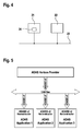
- Fig. 4 shows that a turn signal control unit 22 with an evaluation unit 24, which may be integrated in the navigation system 21, is connected.
- the evaluation unit 24 is connected to the turn signal control unit 22 by a vehicle bus 23.
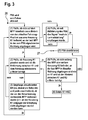
- Fig. 3 the sequence is shown according to a variant of the method in a state diagram.
- the procedure begins as soon as the direction indicator has been activated by the driver (black circle 26).
- the procedure ends as soon as the direction indicator has been deactivated (white circle 27).
- the distance to the previous intersection, from which the turn signal is automatically deactivated, can be defined by a parameter (y).
- step 1 If the driver activates the direction indicator just before or during a turn, it may happen that the corresponding intersection has already been passed in the evaluation of the condition in step 1 according to a most probable route "Most Probable Path" (MPP) and accordingly immediately in the step 4 is changed.
- MPP most probable route
- step 3 a short distance of the already traveled path can be checked for intersections, which were possibly the trigger for the activation of the direction indicator (FRA). If the MPP was abandoned due to a wrong forecast from the Horizon provider, step 3 ensures that the procedure with the new MPP (which is provided by the Horizon Provider after leaving the previous MPP) is immediately restarted without the direction indicator (FRA ) is deactivated in between.
- step 3 could be limited in order to prevent the direction indicator (FRA) from being activated too long for a long sequence of intersections at which the MPP is not bent (eg after a lane change ).
- condition 4 will cause that the direction indicator is switched off as soon as the steering wheel has been moved to the neutral position. This corresponds to the behavior of the conventional deactivation of the turn signal and is used, for example, when changing lanes. It is assumed that a signal from a steering angle sensor is received when the steering wheel is moved from a set position to the neutral position. It should be noted that the deactivation of the direction indicator in step 4 also takes place retroactively. For example, if step 4 is reached due to an error, the steering wheel is not currently in the neutral position, but was already there after activating the turn signal, the turn signal is immediately deactivated automatically.
- steps 5 and 6 ensure that the FRA is not deactivated between the two intersections.
- the maximum distance between the intersections can be set by the parameter z.
- the parameters x, y and z are chosen according to the desired behavior of the system for carrying out the method, possibly also as a function of a driver profile. It is possible for a horizon provider to use the direction indicator signal to determine or influence the MPP. When implementing the method, it must be ensured that no unwanted effects result from this. An example of such an effect is that the turn signal is automatically turned off due to the current MPP, with the MPP being turned off due to this shutdown is changed. In order for the switch-off times to be selected as described, a reliable MPP must be provided, ie the probability must be high that the provided MPP is actually selected by the driver. If the Horizon Provider provides several possible paths that differ in terms of the procedure Fig. 3 and if none of these paths are much more likely to occur than the other paths according to the probabilities provided by the Horizon Provider, then the procedure may be temporarily disabled.
- Fig. 5 illustrates a connection of a so-called ADAS Horizon Provider over a CAN bus with different Reconstructor units.
- the invention is not limited to this example, so the method could be carried out such that the switch-off times are calculated purely geometrically by the analysis of curvatures and inflection points of the MPP.
Landscapes
- Engineering & Computer Science (AREA)
- Mechanical Engineering (AREA)
- Navigation (AREA)
- Lighting Device Outwards From Vehicle And Optical Signal (AREA)
Applications Claiming Priority (1)
| Application Number | Priority Date | Filing Date | Title |
|---|---|---|---|
| DE102013217776.3A DE102013217776B4 (de) | 2013-09-05 | 2013-09-05 | Verfahren zur automatischen Abschaltung eines manuell eingeschalteten Fahrtrichtungsanzeigers eines Kraftfahrzeuges |
Publications (1)
| Publication Number | Publication Date |
|---|---|
| EP2845766A1 true EP2845766A1 (fr) | 2015-03-11 |
Family
ID=51266200
Family Applications (1)
| Application Number | Title | Priority Date | Filing Date |
|---|---|---|---|
| EP14180121.7A Withdrawn EP2845766A1 (fr) | 2013-09-05 | 2014-08-07 | Procédé d'arrêt automatique d'un indicateur de direction enclenché manuellement de véhicule automobile |
Country Status (2)
| Country | Link |
|---|---|
| EP (1) | EP2845766A1 (fr) |
| DE (1) | DE102013217776B4 (fr) |
Cited By (2)
| Publication number | Priority date | Publication date | Assignee | Title |
|---|---|---|---|---|
| WO2023169705A1 (fr) * | 2022-03-07 | 2023-09-14 | Bayerische Motoren Werke Aktiengesellschaft | Indicateur de direction de déplacement et procédé d'affichage d'une direction de déplacement pour un véhicule automobile |
| EP4482709A1 (fr) * | 2022-02-25 | 2025-01-01 | Tesla, Inc. | Automatisation des dispositifs de signalisation associés au fonctionnement d'un véhicule |
Families Citing this family (4)
| Publication number | Priority date | Publication date | Assignee | Title |
|---|---|---|---|---|
| US12377775B2 (en) * | 2020-08-25 | 2025-08-05 | Nissan Motor Co., Ltd. | Vehicle control method and vehicle control device |
| DE102021200926B4 (de) | 2021-02-02 | 2025-03-27 | Volkswagen Aktiengesellschaft | Verfahren zum Betreiben eines Fahrzeugs und Fahrzeug |
| DE102021103675A1 (de) | 2021-02-17 | 2022-08-18 | Valeo Schalter Und Sensoren Gmbh | Verfahren zum betreiben eines fahrerassistenzsystems, computerprogrammprodukt, fahrerassistenzsystem und fahrzeug |
| DE102023003196A1 (de) | 2023-08-03 | 2024-07-18 | Mercedes-Benz Group AG | Verfahren zur Ausgabe eines Hinweises in einem Fahrzeug und Vorrichtung zur Durchführung des Verfahrens |
Citations (10)
| Publication number | Priority date | Publication date | Assignee | Title |
|---|---|---|---|---|
| US506863A (en) | 1893-10-17 | Island | ||
| US4939540A (en) | 1988-05-12 | 1990-07-03 | Alps Electric Co., Ltd. | Winker automatic canceling device |
| DE10251357A1 (de) * | 2002-11-05 | 2004-05-13 | Daimlerchrysler Ag | Setzen oder Abschalten eines Fahrtrichtungsanzeigers |
| DE102004030951A1 (de) | 2004-06-26 | 2006-01-19 | Adam Opel Ag | Instrumententafel und Navigationsgerät für ein Kraftfahrzeug |
| EP1775552A2 (fr) | 2005-10-14 | 2007-04-18 | Robert Bosch Gmbh | Horizon electronique pour systèmes d'assistance à la conduite |
| DE102006020631A1 (de) * | 2006-05-04 | 2007-11-08 | Valeo Schalter Und Sensoren Gmbh | Steuereinrichtung zur Steuerung eines Fahrtrichtungsanzeigers eines Kraftfahrzeugs |
| DE102008011940A1 (de) * | 2008-02-29 | 2009-09-03 | Martin Bokler | Nutzung eines Gerätes zur Positionsbestimmung zur Blinkerrückstellung |
| DE102009047436A1 (de) | 2009-12-03 | 2011-06-09 | Robert Bosch Gmbh | Verfahren zum Rückstellen und/oder Setzen einer Fahrzeugblinkanlage |
| US20120089300A1 (en) * | 2010-10-08 | 2012-04-12 | Wolterman Michael J | Navigation system activation of a vehicular directional signal |
| US20130110347A1 (en) * | 2011-10-28 | 2013-05-02 | Hon Hai Precision Industry Co., Ltd. | Direction indicator control system for vehicle and method for controlling direction indicator lamp |
Family Cites Families (3)
| Publication number | Priority date | Publication date | Assignee | Title |
|---|---|---|---|---|
| JPH0638756Y2 (ja) * | 1989-09-09 | 1994-10-12 | アルプス電気株式会社 | ウインカー用オートキヤンセル装置 |
| JP2731899B2 (ja) * | 1995-07-26 | 1998-03-25 | 株式会社エクォス・リサーチ | 車両のウインカ制御装置 |
| US20050187710A1 (en) * | 2004-02-20 | 2005-08-25 | Walker James A. | Vehicle navigation system turn indicator |
-
2013
- 2013-09-05 DE DE102013217776.3A patent/DE102013217776B4/de active Active
-
2014
- 2014-08-07 EP EP14180121.7A patent/EP2845766A1/fr not_active Withdrawn
Patent Citations (10)
| Publication number | Priority date | Publication date | Assignee | Title |
|---|---|---|---|---|
| US506863A (en) | 1893-10-17 | Island | ||
| US4939540A (en) | 1988-05-12 | 1990-07-03 | Alps Electric Co., Ltd. | Winker automatic canceling device |
| DE10251357A1 (de) * | 2002-11-05 | 2004-05-13 | Daimlerchrysler Ag | Setzen oder Abschalten eines Fahrtrichtungsanzeigers |
| DE102004030951A1 (de) | 2004-06-26 | 2006-01-19 | Adam Opel Ag | Instrumententafel und Navigationsgerät für ein Kraftfahrzeug |
| EP1775552A2 (fr) | 2005-10-14 | 2007-04-18 | Robert Bosch Gmbh | Horizon electronique pour systèmes d'assistance à la conduite |
| DE102006020631A1 (de) * | 2006-05-04 | 2007-11-08 | Valeo Schalter Und Sensoren Gmbh | Steuereinrichtung zur Steuerung eines Fahrtrichtungsanzeigers eines Kraftfahrzeugs |
| DE102008011940A1 (de) * | 2008-02-29 | 2009-09-03 | Martin Bokler | Nutzung eines Gerätes zur Positionsbestimmung zur Blinkerrückstellung |
| DE102009047436A1 (de) | 2009-12-03 | 2011-06-09 | Robert Bosch Gmbh | Verfahren zum Rückstellen und/oder Setzen einer Fahrzeugblinkanlage |
| US20120089300A1 (en) * | 2010-10-08 | 2012-04-12 | Wolterman Michael J | Navigation system activation of a vehicular directional signal |
| US20130110347A1 (en) * | 2011-10-28 | 2013-05-02 | Hon Hai Precision Industry Co., Ltd. | Direction indicator control system for vehicle and method for controlling direction indicator lamp |
Cited By (2)
| Publication number | Priority date | Publication date | Assignee | Title |
|---|---|---|---|---|
| EP4482709A1 (fr) * | 2022-02-25 | 2025-01-01 | Tesla, Inc. | Automatisation des dispositifs de signalisation associés au fonctionnement d'un véhicule |
| WO2023169705A1 (fr) * | 2022-03-07 | 2023-09-14 | Bayerische Motoren Werke Aktiengesellschaft | Indicateur de direction de déplacement et procédé d'affichage d'une direction de déplacement pour un véhicule automobile |
Also Published As
| Publication number | Publication date |
|---|---|
| DE102013217776B4 (de) | 2025-05-22 |
| DE102013217776A1 (de) | 2015-03-05 |
Similar Documents
| Publication | Publication Date | Title |
|---|---|---|
| DE102005027165B4 (de) | Verfahren und Vorrichtung zur Ausgabe von Einparkhinweisen | |
| EP3569465B1 (fr) | Dispositif et système de fourniture d'une fonction d'automatisation pour un véhicule | |
| DE102015006138A1 (de) | Fahrerassistenzsystem und Verfahren zur Vermeidung von Kollisionen | |
| EP3005338B1 (fr) | Système d'aide à la conduite contenant des informations additionnelles complétant une carte routière | |
| DE102009045835B4 (de) | Fehlalarmhandhabung in DAS- und CSW-Systemen unter Verwendung einer Fehlalarmdatenbank und eines Kartendatenbanksensors | |
| WO2019170478A1 (fr) | Unité de commande et procédé de fonctionnement d'une fonction de roulement au niveau d'un système de signalisation | |
| DE102013217776B4 (de) | Verfahren zur automatischen Abschaltung eines manuell eingeschalteten Fahrtrichtungsanzeigers eines Kraftfahrzeuges | |
| DE102013212255A1 (de) | Verfahren zum Austausch von Informationen zwischen mindestens zwei Fahrzeugen | |
| DE102016209330B4 (de) | Verfahren zum Durchführen eines kooperativen Fahrmanövers | |
| EP3631779B1 (fr) | Procédé, dispositifs et support d'enregistrement lisible par ordinateur comprenant des instructions pour déterminer des règles de circulation à appliquer pour un véhicule automobile | |
| EP3356766B1 (fr) | Procédé pour mettre à jour une carte électronique d'un véhicule | |
| DE102009047436A1 (de) | Verfahren zum Rückstellen und/oder Setzen einer Fahrzeugblinkanlage | |
| EP3013658A1 (fr) | Estimation du trajet de conduite d'un véhicule | |
| EP2632784A1 (fr) | Procédé et dispositif pour déterminer un paramétrage de régulation transversale pour une régulation transversale d'un véhicule | |
| WO2017144382A1 (fr) | Dispositif et procédé d'assistance au guidage latéral pour un véhicule routier | |
| EP3678913B1 (fr) | Procédé pour faire fonctionner un système d'aide à la conduite d'un véhicule à moteur et véhicule à moteur | |
| DE102015013467A1 (de) | Ampelassistenzsystem und Betriebsverfahren dafür | |
| DE102016013972A1 (de) | Fahrerassistenzsystem und -verfahren | |
| DE102018004573A1 (de) | Verfahren zum Informieren eines Fahrers eines Fahrzeugs | |
| WO2023036545A1 (fr) | Procédé et circuit de commande servant à vérifier si un mode de conduite actuellement actif est actionné dans sa limite odd, et système et serveur dorsal | |
| EP2910445B1 (fr) | Procédé d'assistance d'un conducteur pour passer dans une voie de circulation rétrécie et système d'assistance du conducteur | |
| WO2014174000A1 (fr) | Procédé permettant l'actionnement automatique d'un indicateur de direction d'un véhicule automobile | |
| EP4165375B1 (fr) | Procédé de détermination d'un type d'utilisation d'un motif de points de repère destinée à une localisation autonome d'un véhicule, et système de localisation autonome électronique d'un véhicule | |
| DE102017222563A1 (de) | Verfahren und Vorrichtung zur Kommunikation zwischen mehreren Kraftfahrzeugen | |
| DE102011083777A1 (de) | Fahrerassistenzsystem und Verfahren zum Betreiben eines Fahrerassistenzsystems |
Legal Events
| Date | Code | Title | Description |
|---|---|---|---|
| 17P | Request for examination filed |
Effective date: 20140807 |
|
| AK | Designated contracting states |
Kind code of ref document: A1 Designated state(s): AL AT BE BG CH CY CZ DE DK EE ES FI FR GB GR HR HU IE IS IT LI LT LU LV MC MK MT NL NO PL PT RO RS SE SI SK SM TR |
|
| AX | Request for extension of the european patent |
Extension state: BA ME |
|
| PUAI | Public reference made under article 153(3) epc to a published international application that has entered the european phase |
Free format text: ORIGINAL CODE: 0009012 |
|
| R17P | Request for examination filed (corrected) |
Effective date: 20150911 |
|
| RBV | Designated contracting states (corrected) |
Designated state(s): AL AT BE BG CH CY CZ DE DK EE ES FI FR GB GR HR HU IE IS IT LI LT LU LV MC MK MT NL NO PL PT RO RS SE SI SK SM TR |
|
| STAA | Information on the status of an ep patent application or granted ep patent |
Free format text: STATUS: EXAMINATION IS IN PROGRESS |
|
| 17Q | First examination report despatched |
Effective date: 20190110 |
|
| RAP1 | Party data changed (applicant data changed or rights of an application transferred) |
Owner name: ROBERT BOSCH GMBH |
|
| STAA | Information on the status of an ep patent application or granted ep patent |
Free format text: STATUS: THE APPLICATION IS DEEMED TO BE WITHDRAWN |
|
| 18D | Application deemed to be withdrawn |
Effective date: 20210507 |